EP2632497B1 - Storage device for endoscopes - Google Patents
Storage device for endoscopes Download PDFInfo
- Publication number
- EP2632497B1 EP2632497B1 EP11749883.2A EP11749883A EP2632497B1 EP 2632497 B1 EP2632497 B1 EP 2632497B1 EP 11749883 A EP11749883 A EP 11749883A EP 2632497 B1 EP2632497 B1 EP 2632497B1
- Authority
- EP
- European Patent Office
- Prior art keywords
- storage device
- securing means
- container portion
- closure
- container
- Prior art date
- Legal status (The legal status is an assumption and is not a legal conclusion. Google has not performed a legal analysis and makes no representation as to the accuracy of the status listed.)
- Active
Links
- 238000003860 storage Methods 0.000 title claims description 67
- 239000012530 fluid Substances 0.000 claims description 8
- 239000000463 material Substances 0.000 claims description 5
- 229920003023 plastic Polymers 0.000 claims description 3
- 239000004033 plastic Substances 0.000 claims description 3
- 238000004140 cleaning Methods 0.000 description 13
- 238000004659 sterilization and disinfection Methods 0.000 description 11
- 238000000034 method Methods 0.000 description 7
- 238000000638 solvent extraction Methods 0.000 description 7
- 238000011109 contamination Methods 0.000 description 6
- 238000012958 reprocessing Methods 0.000 description 6
- 230000000717 retained effect Effects 0.000 description 4
- 238000012864 cross contamination Methods 0.000 description 3
- XLYOFNOQVPJJNP-UHFFFAOYSA-N water Substances O XLYOFNOQVPJJNP-UHFFFAOYSA-N 0.000 description 3
- 208000020406 Creutzfeldt Jacob disease Diseases 0.000 description 2
- 208000003407 Creutzfeldt-Jakob Syndrome Diseases 0.000 description 2
- 208000010859 Creutzfeldt-Jakob disease Diseases 0.000 description 2
- 238000001574 biopsy Methods 0.000 description 2
- 238000001839 endoscopy Methods 0.000 description 2
- 208000015181 infectious disease Diseases 0.000 description 2
- 230000001954 sterilising effect Effects 0.000 description 2
- 206010011409 Cross infection Diseases 0.000 description 1
- 241001465754 Metazoa Species 0.000 description 1
- 206010029803 Nosocomial infection Diseases 0.000 description 1
- 238000005452 bending Methods 0.000 description 1
- 208000005881 bovine spongiform encephalopathy Diseases 0.000 description 1
- 238000005202 decontamination Methods 0.000 description 1
- 230000003588 decontaminative effect Effects 0.000 description 1
- 238000011010 flushing procedure Methods 0.000 description 1
- 230000002496 gastric effect Effects 0.000 description 1
- 230000002458 infectious effect Effects 0.000 description 1
- 238000003780 insertion Methods 0.000 description 1
- 230000037431 insertion Effects 0.000 description 1
- 239000007788 liquid Substances 0.000 description 1
- 238000005192 partition Methods 0.000 description 1
- 238000012545 processing Methods 0.000 description 1
- 230000001681 protective effect Effects 0.000 description 1
- 239000012487 rinsing solution Substances 0.000 description 1
- 238000007789 sealing Methods 0.000 description 1
- 238000000926 separation method Methods 0.000 description 1
- 239000000243 solution Substances 0.000 description 1
- 239000000126 substance Substances 0.000 description 1
- 238000001356 surgical procedure Methods 0.000 description 1
- 201000008827 tuberculosis Diseases 0.000 description 1
Images


Classifications
-
- A—HUMAN NECESSITIES
- A61—MEDICAL OR VETERINARY SCIENCE; HYGIENE
- A61B—DIAGNOSIS; SURGERY; IDENTIFICATION
- A61B50/00—Containers, covers, furniture or holders specially adapted for surgical or diagnostic appliances or instruments, e.g. sterile covers
- A61B50/30—Containers specially adapted for packaging, protecting, dispensing, collecting or disposing of surgical or diagnostic appliances or instruments
- A61B50/33—Trays
-
- A—HUMAN NECESSITIES
- A61—MEDICAL OR VETERINARY SCIENCE; HYGIENE
- A61B—DIAGNOSIS; SURGERY; IDENTIFICATION
- A61B50/00—Containers, covers, furniture or holders specially adapted for surgical or diagnostic appliances or instruments, e.g. sterile covers
- A61B50/30—Containers specially adapted for packaging, protecting, dispensing, collecting or disposing of surgical or diagnostic appliances or instruments
-
- A—HUMAN NECESSITIES
- A61—MEDICAL OR VETERINARY SCIENCE; HYGIENE
- A61L—METHODS OR APPARATUS FOR STERILISING MATERIALS OR OBJECTS IN GENERAL; DISINFECTION, STERILISATION OR DEODORISATION OF AIR; CHEMICAL ASPECTS OF BANDAGES, DRESSINGS, ABSORBENT PADS OR SURGICAL ARTICLES; MATERIALS FOR BANDAGES, DRESSINGS, ABSORBENT PADS OR SURGICAL ARTICLES
- A61L2/00—Methods or apparatus for disinfecting or sterilising materials or objects other than foodstuffs or contact lenses; Accessories therefor
- A61L2/26—Accessories or devices or components used for biocidal treatment
-
- A—HUMAN NECESSITIES
- A61—MEDICAL OR VETERINARY SCIENCE; HYGIENE
- A61B—DIAGNOSIS; SURGERY; IDENTIFICATION
- A61B1/00—Instruments for performing medical examinations of the interior of cavities or tubes of the body by visual or photographical inspection, e.g. endoscopes; Illuminating arrangements therefor
- A61B1/00131—Accessories for endoscopes
- A61B1/0014—Fastening element for attaching accessories to the outside of an endoscope, e.g. clips, clamps or bands
-
- A—HUMAN NECESSITIES
- A61—MEDICAL OR VETERINARY SCIENCE; HYGIENE
- A61B—DIAGNOSIS; SURGERY; IDENTIFICATION
- A61B50/00—Containers, covers, furniture or holders specially adapted for surgical or diagnostic appliances or instruments, e.g. sterile covers
- A61B50/30—Containers specially adapted for packaging, protecting, dispensing, collecting or disposing of surgical or diagnostic appliances or instruments
- A61B50/36—Containers specially adapted for packaging, protecting, dispensing, collecting or disposing of surgical or diagnostic appliances or instruments for collecting or disposing of used articles
-
- A—HUMAN NECESSITIES
- A61—MEDICAL OR VETERINARY SCIENCE; HYGIENE
- A61B—DIAGNOSIS; SURGERY; IDENTIFICATION
- A61B50/00—Containers, covers, furniture or holders specially adapted for surgical or diagnostic appliances or instruments, e.g. sterile covers
- A61B2050/005—Containers, covers, furniture or holders specially adapted for surgical or diagnostic appliances or instruments, e.g. sterile covers with a lid or cover
- A61B2050/0058—Containers, covers, furniture or holders specially adapted for surgical or diagnostic appliances or instruments, e.g. sterile covers with a lid or cover closable by translation
-
- A—HUMAN NECESSITIES
- A61—MEDICAL OR VETERINARY SCIENCE; HYGIENE
- A61B—DIAGNOSIS; SURGERY; IDENTIFICATION
- A61B50/00—Containers, covers, furniture or holders specially adapted for surgical or diagnostic appliances or instruments, e.g. sterile covers
- A61B2050/005—Containers, covers, furniture or holders specially adapted for surgical or diagnostic appliances or instruments, e.g. sterile covers with a lid or cover
- A61B2050/0089—Containers, covers, furniture or holders specially adapted for surgical or diagnostic appliances or instruments, e.g. sterile covers with a lid or cover having permanent closure means
-
- A—HUMAN NECESSITIES
- A61—MEDICAL OR VETERINARY SCIENCE; HYGIENE
- A61B—DIAGNOSIS; SURGERY; IDENTIFICATION
- A61B50/00—Containers, covers, furniture or holders specially adapted for surgical or diagnostic appliances or instruments, e.g. sterile covers
- A61B50/20—Holders specially adapted for surgical or diagnostic appliances or instruments
-
- A—HUMAN NECESSITIES
- A61—MEDICAL OR VETERINARY SCIENCE; HYGIENE
- A61L—METHODS OR APPARATUS FOR STERILISING MATERIALS OR OBJECTS IN GENERAL; DISINFECTION, STERILISATION OR DEODORISATION OF AIR; CHEMICAL ASPECTS OF BANDAGES, DRESSINGS, ABSORBENT PADS OR SURGICAL ARTICLES; MATERIALS FOR BANDAGES, DRESSINGS, ABSORBENT PADS OR SURGICAL ARTICLES
- A61L2202/00—Aspects relating to methods or apparatus for disinfecting or sterilising materials or objects
- A61L2202/10—Apparatus features
- A61L2202/18—Aseptic storing means
- A61L2202/182—Rigid packaging means
-
- A—HUMAN NECESSITIES
- A61—MEDICAL OR VETERINARY SCIENCE; HYGIENE
- A61L—METHODS OR APPARATUS FOR STERILISING MATERIALS OR OBJECTS IN GENERAL; DISINFECTION, STERILISATION OR DEODORISATION OF AIR; CHEMICAL ASPECTS OF BANDAGES, DRESSINGS, ABSORBENT PADS OR SURGICAL ARTICLES; MATERIALS FOR BANDAGES, DRESSINGS, ABSORBENT PADS OR SURGICAL ARTICLES
- A61L2202/00—Aspects relating to methods or apparatus for disinfecting or sterilising materials or objects
- A61L2202/20—Targets to be treated
- A61L2202/24—Medical instruments, e.g. endoscopes, catheters, sharps
Definitions
- the present invention relates to a device for storage of endoscopes.
- the present invention relates to a single-use storage device for components of a piece of medical equipment that retains the components with the piece of medical equipment. More particularly the storage device may be used to store endoscope valves, with the parent flexible endoscope.
- WO2006127230 discloses a sterilization main container with perforated lid, further comprising openings and a snap-fit closure for closing the main container with the lid.
- Flexible medical endoscopes are used for the internal examination of various parts of the human or animal body. They are produced in diameters ranging from 0.02 to 0.6 inches (0.5 to 15 mm) and with lengths of 12 to 120 inches (300 to 3000 mm). The majority of endoscopes have internal channels, down which air, water or accessories may be directed so as to facilitate examinations, or to carry out surgical procedures. Each of these channels typically includes one or more valves used to restrict and/or direct the flow of fluids or air, or allow the passage of instruments through the endoscope.
- the valves typically include a suction valve, an air/water valve, a biopsy valve and a cleaning valve.
- endoscopes Due to the invasive nature of many of the procedures for which flexible medical endoscopes are used, it is necessary that the endoscopes and all the detachable parts and components such as the valves are thoroughly cleaned and disinfected prior to and after each use. Typically endoscopes undergo a manual cleaning procedure before undergoing disinfection and sterilisation procedures.
- the room in which the cleaning and disinfection of the endoscopes are carried out should be in fairly close proximity to the operating theatre or procedure room where the endoscope will be used, to avoid or minimise contamination between these areas. Furthermore, to reduce the possibility of cross-contamination and to allow accurate records to be kept regarding use of the endoscopes and the cleaning and sterilising procedures, all detachable parts of an endoscope should be kept with the parent scope for their entire service life.
- ESGE European Society for Gastrointestinal Endoscopy
- valves and other detachable components must be fully removed from the endoscope, but should be kept with their unique parent endoscope. For example valves cannot be kept plugged into their endoscope ports but must remain with the endoscope.
- Existing methods of keeping endoscope valves with their parent endoscope vary between different countries and, notwithstanding the above guidance, these existing methods are generally considered unsatisfactory when based on such criteria as:
- the present invention provides a single use storage device that allows valves and other components to be kept with a parent endoscope or other piece of medical equipment during storage, cleaning and sterilisation.
- the storage device may be used in hospitals for the storage of flexible medical endoscope valves together with their parent endoscope to ensure that they remain a unique set, before, during and after being processed in an automated reprocessing machine or by manual endoscope reprocessing.
- the storage device further comprises a connecting portion joining the container portion to the closure portion.
- This connecting portion will typically be arranged such that there is a distinct separation of the container portion and closure portion.
- the device comprises a flexible connecting portion joining the container portion to the closure portion.
- the connection portion is arranged such that, when the closure portion is engaged with the container portion the connection portion forms a loop.
- the connection portion comprises a flexible strap which may be bent or looped around an object, such as an endoscope, when the storage device is closed so that the storage device is retained with the object.
- connection portion includes one or more protrusions on a first surface. These are provided so that contact between the connection portion and the object to which the storage device is attached is minimised.
- a strap connecting the container portion to the closure portion may include raised projections to minimise the contact of the strap with a parent endoscope umbilical (light-guide) cable around which the strap is looped.
- the device To enable a sufficient flow of fluid through the device it is desirable to include a plurality of apertures in both the container portion and the closure portion.
- the apertures will comprise holes through the base and/or walls of the container portion and closure portion.
- a first part of the securing means is provided in the container portion and a second part of the securing means in provided in the closure portion.
- the securing means comprises an opening the container portion and a protrusion in the closure portion, and wherein a part of the protrusion is passed through the opening to secure the closure portion to the container portion.
- the securing means may comprise more than one opening and more than one protrusion.
- the storage device is designed to be used only once, to minimise contamination of medical equipment for example, it is preferable to design the securing means so that disabling the securing means includes breaking a part of the securing means.
- the closure portion includes a handle portion. The handle portion is arranged to enable a user to grip the handle to separate the closure portion from the container portion, thereby disabling or breaking the securing means.
- the container portion may include a partitioning member, which divides at least a part of the volume of the container portion into discrete regions.
- the closure portion is a lid.
- the container portion may comprise a tray compartment.
- the closure portion is preferably in the form of a sleeve, and the tray compartment is receivable within the sleeve.
- the tray compartment and sleeve are substantially rectangular in shape and are arranged such that the tray compartment is received completely within the sleeve to form a substantially rectangular box, or cage.
- a first part of the securing means is provided on the tray compartment and a second part of the securing means is provided on the sleeve.
- the first and second parts of the securing means comprise a plurality of semi-dome protrusions arranged such that when the tray compartment is engaged with the sleeve, flat surfaces of the protrusions interlock to prevent disengagement of the tray compartment from the sleeve.
- the container portion and closure portion are formed from a plastics material.
- the material from which the storage device is made should, ideally, be resistant to all modern cleaning chemicals.
- the storage device comprises further apertures or grooves that enable chains, ties or similar to pass outside of the device so that, for example, instruction cards or labels that are connected to the valves via the chains or ties can be kept outside the device.
- the storage device of the present invention is required to have a number of key properties.
- the device must be resistant to the cleaning and sterilisation fluids to which it will be exposed, and must be generally tough and durable.
- the storage device must protect its contents from damage and as such should be substantially rigid and robust.
- the device while containing the valves or other components, must permit fluids to flow into and out of the device quickly and easily.
- FIG. 1 A first embodiment of the storage device 20 is illustrated in Figures 1 and 3 .
- the storage device 20 comprises a tray compartment 1 and a sleeve 5.
- the tray compartment 1 is defined by a substantially rectangular base 2 and surrounding side walls 3 and end walls 4 upstanding therefrom on each side.
- Each wall 3, 4 is, preferably, curved at each end and at the bottom thereof, such that each side wall 3 merges imperceptibly with an adjacent end wall 4, and with the base 2.
- the tray compartment 1 is required to be large enough to accommodate various flexible medical endoscope valves of different sizes without undue stress being applied to the valves, yet must at the same time be small enough to fit into a standard automated endoscope reprocessing (AER) machine.
- endoscope valves include suction, air/water, biopsy and A/W cleaning valves.
- the side walls 3 along the length of the base ideally have an external length of about 100mm, whilst the end walls 4 ideally have an external length of about 70 mm.
- the depth of the tray compartment 1 is ideally about 50mm.
- a sleeve 5 receives the tray compartment 1 through an open end.
- the sleeve 5 may be closed at the other end, or if it is open, then an end of the tray compartment 1 will act to close it.
- the sleeve 5 has internal dimensions which correspond to the external dimensions of the tray compartment 1 to ensure a close fit once assembled together.
- the sleeve 5 might have an internal length of about 105mm, an internal width of about 75 mm and an internal depth of about 55mm, although these dimensions may vary depending on the thickness of the material that the tray compartment is constructed from.
- a strap 13 connects the tray compartment 1 to the sleeve 5, a first end of the strap 13 being attached to a corner of the tray compartment 1 and a second end of the strap 13 being attached to a corner of the sleeve 5.
- Figure 2 shows an underside view of Figure 1 , wherein the base of the sleeve 5 has a detachable portion 9 in the form of a tear-off disassembly strip, which can be removed from the sleeve 5 when sufficient force is applied.
- the detachable portion 9 is, ideally, defined by a perforated edge and, preferably, has a tab 10 extending from one side to facilitate detachment.
- the underside 6 of the tray compartment 1 contains a number of struts 7 which extend across the width of the tray compartment 1.
- Each strut 7 has a number of moulded protrusions 8 provided on it that are arranged to engage with a corresponding number of moulded protrusions 12 provided on a corresponding number of struts 11 on the sleeve 5 when the tray compartment 1 is inserted into the sleeve 5.
- the protrusions 8, 12 are, preferably, formed as semi-domes and arranged such that, when the tray compartment 1 is inserted into the sleeve 5, the rounded parts of each semi-dome protrusion 8, 12 pass over each other.
- the struts 11 on the sleeve 5 are arranged on the detachable portion 9 of the sleeve 5, which allows the tray compartment 1 to be released by removing the detachable portion 9 and hence the struts 11 with the protrusions 12 from the sleeve 5. Removal of the detachable portion 9 renders the device unusable for a second time because there are no longer any sleeve protrusions 12 for the tray compartment protrusions 8 to interlock with, thus ensuring the single-use nature of the device.
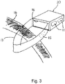
- FIG 3 shows the sleeve 5 with the tray compartment 1 fully inserted and retained therein. Furthermore, it can be seen that the strap 13 is arranged such that when the tray compartment 1 is fully inserted inside the sleeve 5, the strap 13 can be passed around an endoscope umbilical (light-guide) cable 14 when the tray compartment 1 is being inserted into the sleeve 5 to form a loop that encompasses the endoscope cable 14 so as to ensure that the assembled device remains with the parent endoscope until the detachable portion 9 is detached from the base of the sleeve 5, preferably by means of applying a sufficient force to the tab 10.
- an endoscope umbilical (light-guide) cable 14 when the tray compartment 1 is being inserted into the sleeve 5 to form a loop that encompasses the endoscope cable 14 so as to ensure that the assembled device remains with the parent endoscope until the detachable portion 9 is detached from the base of the sleeve 5, preferably by means of applying a sufficient force to the
- the strap 13 has to be long enough to enable the valve tray 1 to be inserted into the sleeve 5 and will therefore ideally be about 15cm long.
- the strap 13 has moulded raised projections 15 on both sides to minimise contact between the strap 13 and endoscope cable 14 during a reprocessing procedure.
- Both the tray compartment 1 and the sleeve 5 have a plurality of apertures 17 throughout their structures to allow flow of cleaning, disinfection and rinsing solutions during the automated endoscope reprocessing cycle.
- a used endoscope When a used endoscope is to be to be cleaned, by placing it into an automated endoscope reprocessor, for example, its valves are removed from the positions on the endoscope and placed in the tray compartment 1.
- valves will have a chain, or similar, attached with a plastic instruction card on it.
- a groove 16 is provided in a side wall 3 of the tray compartment 1 that is exposed at an end of the sleeve to allow the chain to pass outside of the tray compartment 1 before it is inserted into the sleeve 5, to keep any instruction card outside of the tray compartment 1, where they can be easily accessed.
- the device will ensure that the endoscope valves stay with their parent endoscope during reprocessing of the endoscope and subsequent storage until the endoscope is ready to be used again.
- retrieval of the endoscope valves can be facilitated by removing the detachable portion 9, thereby allowing the tray compartment 1 to be removed from the sleeve 5.
- the used tray compartment 1 and sleeve 5 are then discarded and new ones used when the endoscope is next reprocessed.
- the present invention has been developed particularly for use in keeping valves as a unique set with flexible medical endoscopes and hence is described herein with particular reference to that use. Nevertheless, it will be appreciated that the present invention may also find use in the safe storage of other medical equipment and/or any other situation where it is important that instrument detachable parts be kept together with the parent item using a single-use product.
- the protrusions 8, 12 may be provided along one or both sides of the tray compartment 1 and sleeve 5, respectively, in which case the detachable portion 9 could be provided on the side(s) of the sleeve 5 to remove the sleeve protrusions 12.
- the detachable portion 9 may not be arranged to remove the protrusions 12 from the sleeve 5, but could instead be provided on the top of the sleeve 5, such that its removal will allow the tray compartment 1 to be accessed whilst leaving the securing portions 8. 12 interlocked, thereby ensuring that the device can only be used once.
- one of the plurality of protrusions 8, 12 could be substituted by a corresponding number of holes, or slots, provided in the respective struts 7, 11, whereby the semi-dome protrusions can pass into and out of the holes or slots when the tray compartment 1 is being inserted into the sleeve 5, but the flat sides of the protrusions will lock against the flat sides of the holes or slots if any attempt is made to retract the tray compartment 1 from the sleeve 5.
- the plurality of struts could be arranged in a similar semi-dome fashion the length of the strut, such that the flat sides of corresponding struts 7, 11 will interlock.
- the protrusions could also be staggered on corresponding struts 7, 11 so that there is no interference between protrusions 8, 12 that are not intended to interlock when the tray compartment 1 is being inserted into the sleeve 5.
- Another alternative arrangement might be to substitute the sleeve 5 for a lid, which can be arranged to engage with and close the tray compartment 1 using snap-fit securing components, or similar, that are single-use such that disengagement of the lid would only be possible by disabling the securing components used to secure it to the tray compartment 1, or by accessing the tray compartment 1 from above using a detachable portion 9.
- the lid may be in the shape of an open box, with sides that extend down from the lid sides, such that when the lid is placed over the tray compartment 1, the sides extend down and over the side walls 3 of the tray compartment 1.
- the protrusions 8, 12, holes/slots, or similar, and detachable portion 9 to remove them could be provided on the side walls 3 of the tray compartment and lid sides, respectively.
- a storage device 30 comprises a first, container portion 32 and a second, lid portion 34.
- a connecting portion or strap 36 connects the container portion 32 to the lid portion 34.
- the lid portion 34 engages with the container portion 32 to form an enclosure that surrounds one or more pieces of medical equipment placed within the container portion 32.
- the container portion 32 comprises a generally circular base 38 and a side wall 40 that extends from the periphery of the base 38 to a top edge 42 of the container portion 32, thereby defining an interior space 44 and an opening 46 of the container portion 32.
- a flange or rim 48 extends outwards from the top edge 42 around the complete periphery of the edge 42.
- an outer edge 50 of the rim 48 is generally square-shaped thereby defining four corner regions 52 of the rim 48.
- Regions of the side wall 40 terminating at the corner regions 52 of the rim 48 are of a greater height than regions of the side wall 40 between the corner regions 52. In this way, the corner regions 52 of the rim 48 are raised compared to side regions 54 of the rim 48, between the corner regions 52, and, as such, four dips or recesses 56 are created in the rim 48 between the corner regions 52.
- a plurality of holes 58 are formed in the base 38 of the container portion 32, and preferably the holes 58 are spaced evenly over the full area of the base 38.
- the side wall 40 comprises a plurality of elongate apertures 60 that extend from proximate the base 38 to proximate the top edge 42 and which are spaced evenly around the side wall 40.
- the container portion 32 further includes partitioning members 62 that extend across the base 38 of the container portion 32 to divide the base 38 into distinct areas.
- the partitioning members 62 comprise walls 62 that extend from a central point 64 out to the side wall 40 of the container portion 32.
- the container portion 32 may not include partitioning members, or may include less than or more than four partitioning members.
- the partitioning members may be of any suitable form and may divide the base of the container portion into uneven or irregularly sized areas.
- the base 38 of the container portion 32 includes a ridge 65 extending from the underside, or exterior, surface of the container portion 32.
- the device 30 may be stood on the ridge 65 so that fluid is still able to drain from the holes 58 in the base 38.
- the lid portion 34 comprises a generally circular central section 66 and a side wall 68 extending around the central section 66, thereby defining a recessed space 67 in the underside 69 of the lid 34.
- a rim 70 extends outwards from a top edge 72 of the side wall 68.
- An outer edge 74 of the rim 70 is generally square-shaped thereby defining four corner regions 76 of the rim 70.
- the dimensions of the lid portion 34 correspond to the dimensions of the container portion 32, and in particular the dimensions of the rim 70 are substantially the same as the dimensions of the rim 48.
- a plurality of holes 78 are formed in the central section 66 of the lid portion 34, and a plurality of elongate apertures 80 are formed in the side wall 68 extending from the central section 66 to the top edge 72.
- the strap 36 is connected at a first end 82 to the rim 48 of the container portion 32 and at a second end 84 to the rim 70 of the lid portion 34.
- the width of the strap 36 is substantially less than a width of the container portion 32, and in this example, the strap 36 extends from a side region 54 of the rim 48 to a first side region 77 of the rim 70.
- the strap 36 is flexible, and in this embodiment, the thickness of the strap 36 is the same as the thickness of both the rims 48, 70, and a first side 86 of the strap 36 is integral or flush with a top surface 88 of the rim 48 and an underside surface 69 of the rim 70.
- the strap 36 comprises a plurality of holes 92 spaced along the length of the strap 36.
- a plurality of ribs 94 extend across the width of the strap 36 on the first side 86 of the strap 36 and each one of the plurality of ribs 94 is located between two holes 92.
- the ribs 94 do not extend across the full width of the strap in this example, but in other embodiments the ribs may extend for the full width of the strap and there may be fewer or more ribs than holes.
- a handle portion or grip portion 96 extends from a second side region 77 of the rim 70, opposite to the first side region 77.
- the handle portion 96 comprises a tab 98 formed from a planar sheet having the same thickness as the rim 70.
- the tab 98 includes a centrally positioned hole 100, through which a user of the device may place one or more fingers as will be described below.
- the device 30 further comprises securing means 122, the first part 123 of the securing means 122 being located on the container portion 32 and a second part 124 of the securing means 122 being located on the lid portion 34, as shown most clearly in Figures 7-10 .
- the first part 123 of the securing means 122 comprises a cavity 126 formed in the rim 48.
- the cavity 126 has an opening 128 in the top surface 88 of the rim 48, for receiving the second part 124 of the securing means 122.
- the cavity 126 is substantially enclosed, and in particular, a base 130 of the cavity 126 is formed by a part of the undesired surface 132 of the rim 48.
- the second part 124 of the securing means 122 comprises a locking member 134 projecting substantially perpendicularly from the underside surface 90 of the rim 70.
- the locking member 134 comprises a stem portion 136 and a head portion 138.
- the head portion 138 comprises two arms or barbs 140 that extend outwards and rearwards from the distal end 142 of the locking member 134. In this way, the barbs 140 extend back towards the underside surface 90 on the rim 70.
- the distance between the ends 144 of the barbs 140 is greater than the width of the opening 128 of the first part 123 of the securing means 122, such that deflection of the barbs 140 is required to insert the locking member 134 into the cavity 126.
- Figures 9 and 10 show the storage device 30 in a closed configuration in which the first and second parts 123, 124 of the securing means 122 are fully engaged. In this position, the head portion 138 of the locking member 134 is fully received within the cavity 126. The ends 144 of the barbs 140 are located behind part of the top surface 88 of the rim 48 surrounding the opening 128. In this way, once the first and second parts 123, 124 of the securing means 122 have been fully engaged it is not possible to withdraw the locking member 134 from the cavity 126 due to the presence of the barbs 140.
- the storage device 30 comprises four securing means 122, one of the securing means 122 being located in each corner region 52, 76 of the rims 48, 70.
- the storage device 30 may also comprise additional engaging means 146 to aid in the alignment and sealing of the lid portion 34 with the container portion 32.
- the engaging means 146 comprises a recess 148 formed in the rim 48 of the container portion 32 and a protrusion 150 extending from the rim 70 of the lid portion 34.
- the recess 148 and the protrusion 150 are arranged such that the protrusion 150 is received within the recess 148 when the lid portion 34 is aligned with and secured over the container portion 32.
- the engaging means 146 comprises four recesses 148 located adjacent to the cavities 126 in the corner regions 52 of the rim 48 and four protrusions 150 located adjacent to the locking members 134 in each of the four corner regions 76 of the rim 70.
- this view shows the device 30 in an open configuration before use.
- a user of the device 30 places the required valves or other components (not shown) into the interior space 44 of the container portion 32.
- the required valves or other components may be placed in the container portion 32, one in each of the areas bounded by the partitioning walls 62.
- the device 30 is then closed by bending the strap 36 around the parent endoscope and placing the lid 34 over the opening 46 of the container portion 32, as shown in Figure 5 .
- the rims 48, 70 are aligned using the engaging means 146 and are pressed together so that the locking members 134 are pushed through the openings 128.
- the resilient barbs 140 of the head portion 138 of each locking member 134 deforms slightly as it is pushed through the respective opening 128.
- the barbs 140 then return to their original shape once through the opening 128 such that the head portion 138 of the locking member 134 is retained within the cavity 126.
- the top surfaces 88 of the corner regions 52 of the rim 48 are in contact with the underside surface 69 of the corner regions 76 of the rim 70.
- the recesses 56 mean that the lower side regions 54 of the rim 48 are not in contact with the respective side regions 77 of the rim 70 and, as such, the recesses 56 form additional openings 57 between the interior space 44 of the container portion 32 and the surroundings.
- valves will typically have an instruction or record card attached to them by means of a chain or similar.
- the chains or other attachment means may be laid within the recess 56, so that, when the device 30 is closed, the chains or similar pass out of the container portion 32 through the openings 57 so that the instruction or record cards remain on the outside of the device 30 for ease of access at all times.
- the strap 36 is wrapped around a portion of the parent endoscope as the device 30 is closed. In this way, the portion of the parent endoscope is contained within a closed loop 152 of the strap 36.
- the ribs 94 on the strap 36 are located on the inner surface of the loop 152 and act to minimise the contact of the strap 36 with the parent endoscope.
- the plurality of holes and apertures 56, 60, 78, 80 both in the container portion 32 and the lid portion 34 allow fluid to flow into and out of the interior space 44 of the device 30.
- the number of holes and apertures 56, 60, 78, 80 should not be too great, such that the rigidity and robustness of the container portion 32 and lid portion 34 are affected, thereby compromising the protective nature of the storage device 30.
- a user When a user wishes to remove the valves or components from the container portion 32, he or she grips the container portion 32 of the device 30 and pulls the handle portion 96 of the lid portion 34. Preferably the user inserts one or more fingers through the hole 100 in the tab 98 in order to apply sufficient force to pull the lid portion 34 away from the container portion 32.
- the force the user applies to the lid portion 34 breaks the slender stem portions 136 of each of the locking members 134.
- the lid portion 34 can then be pulled away from the container portion 32, the strap 36 can be unwrapped from the parent endoscope, and the valves or components removed from the container portion 32.
- the head portions 138 of the locking members 134 remain within the cavities 126 when the device 30 is opened.
- Figure 11 shows three storage devices 30 stacked for the purposes of transportation and storage.
- the design of the storage device 30 means that the container portions 32 and lid portions 34 of the devices 30 nest together such that each storage device 30 only takes up a minimal amount of space.
- the storage device 30 of the present invention therefore, overcomes many of the problems associated with current storage devices.
- the present invention provides a single use storage device that allows valves and other components to be kept with a parent endoscope or other piece of medical equipment during storage, cleaning and sterilisation.
Description
- The present invention relates to a device for storage of endoscopes. In particular, the present invention relates to a single-use storage device for components of a piece of medical equipment that retains the components with the piece of medical equipment. More particularly the storage device may be used to store endoscope valves, with the parent flexible endoscope.
-
WO2006127230 discloses a sterilization main container with perforated lid, further comprising openings and a snap-fit closure for closing the main container with the lid. - Flexible medical endoscopes are used for the internal examination of various parts of the human or animal body. They are produced in diameters ranging from 0.02 to 0.6 inches (0.5 to 15 mm) and with lengths of 12 to 120 inches (300 to 3000 mm). The majority of endoscopes have internal channels, down which air, water or accessories may be directed so as to facilitate examinations, or to carry out surgical procedures. Each of these channels typically includes one or more valves used to restrict and/or direct the flow of fluids or air, or allow the passage of instruments through the endoscope. The valves typically include a suction valve, an air/water valve, a biopsy valve and a cleaning valve.
- Due to the invasive nature of many of the procedures for which flexible medical endoscopes are used, it is necessary that the endoscopes and all the detachable parts and components such as the valves are thoroughly cleaned and disinfected prior to and after each use. Typically endoscopes undergo a manual cleaning procedure before undergoing disinfection and sterilisation procedures.
- At least in the United Kingdom and France, the recent BSE (Bovine Spongiform Encephalopathy) crisis has led to heightened concerns that the human form, Creutzfeldt-Jakob Disease (CJD), may be transmitted by contaminated endoscopes or their detachable parts. Moreover, the recent re-emergence of tuberculosis also presents a threat of airborne contamination in areas where endoscopes are being used and transported.
- Ideally, the room in which the cleaning and disinfection of the endoscopes are carried out should be in fairly close proximity to the operating theatre or procedure room where the endoscope will be used, to avoid or minimise contamination between these areas. Furthermore, to reduce the possibility of cross-contamination and to allow accurate records to be kept regarding use of the endoscopes and the cleaning and sterilising procedures, all detachable parts of an endoscope should be kept with the parent scope for their entire service life.
- At least two Guidelines regarding the use, storage and cleaning of endoscopes have recently been published. These state that endoscope valves and other detachable components should always remain as a unique set with the parent endoscope. The National Endoscopy Programme (UK) in its Decontamination Standards for Flexible Endoscopes states that: "Reusable valves should be decontaminated... and processed with their corresponding endoscope" and "Valves including flushing valves and removable parts are [to be] kept with the endoscope to form a unique set of equipment."
- In addition, the European Society for Gastrointestinal Endoscopy (ESGE) guidelines states that: "Valves should be disconnected as they may block the air flow through the endoscope channels. Valves and distal caps should be stored separately but with the endoscope. Valves (including rinsing valves) should stay with a named endoscope as a set, to prevent cross-infection and enable full traceability."
- It is therefore clear that valves and other detachable components must be fully removed from the endoscope, but should be kept with their unique parent endoscope. For example valves cannot be kept plugged into their endoscope ports but must remain with the endoscope. Existing methods of keeping endoscope valves with their parent endoscope vary between different countries and, notwithstanding the above guidance, these existing methods are generally considered unsatisfactory when based on such criteria as:
- the protection of the endoscope valves before, during and after the processing of the endoscope and valves, either manually or in an automated endoscope reprocessor (AER), against accidental damage or contamination;
- the protection of the staff, patients, and workplace against contamination and possible infection. The risk of contamination deriving from a used and potentially unclean set of endoscope valves due to either the use of non-dedicated cages to store the valves which have a small mesh thus not allowing disinfection solution through, or the use of non-dedicated material bags to store the valves which soak up liquid and can themselves potentially become a biohazard; and
- the protection of unused endoscopes against the potential for cross-contamination from contact with used endoscope valves carrying infectious matter.
- It is an object of the present invention to provide a device that addresses the above-stated problems associated with keeping endoscope valves with their parent endoscope during cleaning and storage.
- According to the invention there is provided a single-use storage device for medical equipment, which is defined in
claim 1. - As such, the present invention provides a single use storage device that allows valves and other components to be kept with a parent endoscope or other piece of medical equipment during storage, cleaning and sterilisation. In particular, the storage device may be used in hospitals for the storage of flexible medical endoscope valves together with their parent endoscope to ensure that they remain a unique set, before, during and after being processed in an automated reprocessing machine or by manual endoscope reprocessing.
- The storage device further comprises a connecting portion joining the container portion to the closure portion. This connecting portion will typically be arranged such that there is a distinct separation of the container portion and closure portion. Preferably the device comprises a flexible connecting portion joining the container portion to the closure portion. The connection portion is arranged such that, when the closure portion is engaged with the container portion the connection portion forms a loop. Preferably the connection portion comprises a flexible strap which may be bent or looped around an object, such as an endoscope, when the storage device is closed so that the storage device is retained with the object.
- In preferred embodiments the connection portion includes one or more protrusions on a first surface. These are provided so that contact between the connection portion and the object to which the storage device is attached is minimised. For example, a strap connecting the container portion to the closure portion may include raised projections to minimise the contact of the strap with a parent endoscope umbilical (light-guide) cable around which the strap is looped.
- To enable a sufficient flow of fluid through the device it is desirable to include a plurality of apertures in both the container portion and the closure portion. Typically the apertures will comprise holes through the base and/or walls of the container portion and closure portion.
- Preferably a first part of the securing means is provided in the container portion and a second part of the securing means in provided in the closure portion. In some embodiments, the securing means comprises an opening the container portion and a protrusion in the closure portion, and wherein a part of the protrusion is passed through the opening to secure the closure portion to the container portion. The securing means may comprise more than one opening and more than one protrusion.
- Because the storage device is designed to be used only once, to minimise contamination of medical equipment for example, it is preferable to design the securing means so that disabling the securing means includes breaking a part of the securing means. To allow a user to easily break open the storage device, it is preferable if the closure portion includes a handle portion. The handle portion is arranged to enable a user to grip the handle to separate the closure portion from the container portion, thereby disabling or breaking the securing means.
- To enable more than one component to be held securely within the storage device, the container portion may include a partitioning member, which divides at least a part of the volume of the container portion into discrete regions.
- In preferred embodiments of the invention the closure portion is a lid.
- The container portion may comprise a tray compartment. In embodiments in which the container portion is a tray compartment, the closure portion is preferably in the form of a sleeve, and the tray compartment is receivable within the sleeve. Preferably the tray compartment and sleeve are substantially rectangular in shape and are arranged such that the tray compartment is received completely within the sleeve to form a substantially rectangular box, or cage.
- In embodiments comprising a tray and a sleeve, preferably a first part of the securing means is provided on the tray compartment and a second part of the securing means is provided on the sleeve. In some embodiments it may be preferable if the first and second parts of the securing means comprise a plurality of semi-dome protrusions arranged such that when the tray compartment is engaged with the sleeve, flat surfaces of the protrusions interlock to prevent disengagement of the tray compartment from the sleeve.
- Preferably the container portion and closure portion are formed from a plastics material. The material from which the storage device is made should, ideally, be resistant to all modern cleaning chemicals.
- Preferably the storage device comprises further apertures or grooves that enable chains, ties or similar to pass outside of the device so that, for example, instruction cards or labels that are connected to the valves via the chains or ties can be kept outside the device.
- The invention will now be further described, by way of example only, and with reference to the accompanying drawings, in which:
-
Figure 1 shows an orthogonal view of a storage device including a tray compartment and sleeve, according to a first embodiment of the present invention, before engagement of the tray compartment with the sleeve; -
Figure 2 shows an underside view of the tray compartment and sleeve ofFigure 1 , having projections arranged to interlock; -
Figure 3 shows the device ofFigures 1 and 2 with the tray compartment retained within the sleeve following insertion, with a strap attaching the device around a parent endoscope umbilical cable; -
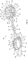
Figure 4 is a view of a storage device according to a second preferred embodiment of the present invention, the storage device shown in an open configuration before use; -
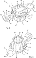
Figure 5 is a perspective view from the top of the storage device ofFigure 4 in a closed configuration; -
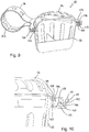
Figure 6 is a perspective view from underneath the storage device ofFigure 5 ; -
Figure 7 is a cross-sectional view through the storage device ofFigure 5 in a partially open configuration, before securing means are engaged; -
Figure 8 is a detailed view of the securing means ofFigure 7 ; -
Figure 9 is a cross-sectional view through the storage device ofFigure 5 in a fully closed configuration, with the securing means engaged; -
Figure 10 is a detailed view of the securing means ofFigure 9 ; and -
Figure 11 is a view of three storage devices ofFigure 4 , showing the devices stacked for storage and transportation. - The storage device of the present invention is required to have a number of key properties. The device must be resistant to the cleaning and sterilisation fluids to which it will be exposed, and must be generally tough and durable. The storage device must protect its contents from damage and as such should be substantially rigid and robust. Finally, the device, while containing the valves or other components, must permit fluids to flow into and out of the device quickly and easily.
- A first embodiment of the
storage device 20 is illustrated inFigures 1 and3 . In this embodiment, thestorage device 20 comprises atray compartment 1 and asleeve 5. - Referring first to
Figure 1 , thetray compartment 1 is defined by a substantiallyrectangular base 2 and surroundingside walls 3 and endwalls 4 upstanding therefrom on each side. Eachwall side wall 3 merges imperceptibly with anadjacent end wall 4, and with thebase 2. - The
tray compartment 1 is required to be large enough to accommodate various flexible medical endoscope valves of different sizes without undue stress being applied to the valves, yet must at the same time be small enough to fit into a standard automated endoscope reprocessing (AER) machine. Typically, endoscope valves include suction, air/water, biopsy and A/W cleaning valves. - Therefore it is preferred that the
side walls 3 along the length of the base ideally have an external length of about 100mm, whilst theend walls 4 ideally have an external length of about 70 mm. The depth of thetray compartment 1 is ideally about 50mm. - A
sleeve 5 receives thetray compartment 1 through an open end. Thesleeve 5 may be closed at the other end, or if it is open, then an end of thetray compartment 1 will act to close it. - The
sleeve 5 has internal dimensions which correspond to the external dimensions of thetray compartment 1 to ensure a close fit once assembled together. As an example, thesleeve 5 might have an internal length of about 105mm, an internal width of about 75 mm and an internal depth of about 55mm, although these dimensions may vary depending on the thickness of the material that the tray compartment is constructed from. - A
strap 13 connects thetray compartment 1 to thesleeve 5, a first end of thestrap 13 being attached to a corner of thetray compartment 1 and a second end of thestrap 13 being attached to a corner of thesleeve 5. -
Figure 2 shows an underside view ofFigure 1 , wherein the base of thesleeve 5 has a detachable portion 9 in the form of a tear-off disassembly strip, which can be removed from thesleeve 5 when sufficient force is applied. The detachable portion 9 is, ideally, defined by a perforated edge and, preferably, has atab 10 extending from one side to facilitate detachment. - The
underside 6 of thetray compartment 1 contains a number of struts 7 which extend across the width of thetray compartment 1. Each strut 7 has a number of moulded protrusions 8 provided on it that are arranged to engage with a corresponding number of mouldedprotrusions 12 provided on a corresponding number of struts 11 on thesleeve 5 when thetray compartment 1 is inserted into thesleeve 5. Theprotrusions 8, 12 are, preferably, formed as semi-domes and arranged such that, when thetray compartment 1 is inserted into thesleeve 5, the rounded parts of eachsemi-dome protrusion 8, 12 pass over each other. - However, if an attempt is made to retract the
tray compartment 1 once it has been inserted into thesleeve 5, the flat sides of thesemi-dome protrusions 8, 12 interlock to prevent thetray compartment 1 from being retracted from thesleeve 5 hence providing a secure storage device. - The struts 11 on the
sleeve 5 are arranged on the detachable portion 9 of thesleeve 5, which allows thetray compartment 1 to be released by removing the detachable portion 9 and hence the struts 11 with theprotrusions 12 from thesleeve 5. Removal of the detachable portion 9 renders the device unusable for a second time because there are no longer anysleeve protrusions 12 for the tray compartment protrusions 8 to interlock with, thus ensuring the single-use nature of the device. -
Figure 3 shows thesleeve 5 with thetray compartment 1 fully inserted and retained therein. Furthermore, it can be seen that thestrap 13 is arranged such that when thetray compartment 1 is fully inserted inside thesleeve 5, thestrap 13 can be passed around an endoscope umbilical (light-guide)cable 14 when thetray compartment 1 is being inserted into thesleeve 5 to form a loop that encompasses theendoscope cable 14 so as to ensure that the assembled device remains with the parent endoscope until the detachable portion 9 is detached from the base of thesleeve 5, preferably by means of applying a sufficient force to thetab 10. - The
strap 13 has to be long enough to enable thevalve tray 1 to be inserted into thesleeve 5 and will therefore ideally be about 15cm long. Thestrap 13 has moulded raisedprojections 15 on both sides to minimise contact between thestrap 13 andendoscope cable 14 during a reprocessing procedure. - Both the
tray compartment 1 and thesleeve 5 have a plurality of apertures 17 throughout their structures to allow flow of cleaning, disinfection and rinsing solutions during the automated endoscope reprocessing cycle. - When a used endoscope is to be to be cleaned, by placing it into an automated endoscope reprocessor, for example, its valves are removed from the positions on the endoscope and placed in the
tray compartment 1. - Often valves will have a chain, or similar, attached with a plastic instruction card on it. Ideally, a
groove 16 is provided in aside wall 3 of thetray compartment 1 that is exposed at an end of the sleeve to allow the chain to pass outside of thetray compartment 1 before it is inserted into thesleeve 5, to keep any instruction card outside of thetray compartment 1, where they can be easily accessed. - Once assembled with the
strap 13 passing around theendoscope cable 14, the device will ensure that the endoscope valves stay with their parent endoscope during reprocessing of the endoscope and subsequent storage until the endoscope is ready to be used again. At this point retrieval of the endoscope valves can be facilitated by removing the detachable portion 9, thereby allowing thetray compartment 1 to be removed from thesleeve 5. The usedtray compartment 1 andsleeve 5 are then discarded and new ones used when the endoscope is next reprocessed. - The present invention has been developed particularly for use in keeping valves as a unique set with flexible medical endoscopes and hence is described herein with particular reference to that use. Nevertheless, it will be appreciated that the present invention may also find use in the safe storage of other medical equipment and/or any other situation where it is important that instrument detachable parts be kept together with the parent item using a single-use product.
- It will, of course, be appreciated that other arrangements may be possible according to the present invention. For example, the
protrusions 8, 12 may be provided along one or both sides of thetray compartment 1 andsleeve 5, respectively, in which case the detachable portion 9 could be provided on the side(s) of thesleeve 5 to remove thesleeve protrusions 12. - Alternatively, the detachable portion 9 may not be arranged to remove the
protrusions 12 from thesleeve 5, but could instead be provided on the top of thesleeve 5, such that its removal will allow thetray compartment 1 to be accessed whilst leaving the securing portions 8. 12 interlocked, thereby ensuring that the device can only be used once. - Furthermore, one of the plurality of
protrusions 8, 12 could be substituted by a corresponding number of holes, or slots, provided in the respective struts 7, 11, whereby the semi-dome protrusions can pass into and out of the holes or slots when thetray compartment 1 is being inserted into thesleeve 5, but the flat sides of the protrusions will lock against the flat sides of the holes or slots if any attempt is made to retract thetray compartment 1 from thesleeve 5. Similarly, the plurality of struts could be arranged in a similar semi-dome fashion the length of the strut, such that the flat sides of corresponding struts 7, 11 will interlock. The protrusions could also be staggered on corresponding struts 7, 11 so that there is no interference betweenprotrusions 8, 12 that are not intended to interlock when thetray compartment 1 is being inserted into thesleeve 5. - Another alternative arrangement might be to substitute the
sleeve 5 for a lid, which can be arranged to engage with and close thetray compartment 1 using snap-fit securing components, or similar, that are single-use such that disengagement of the lid would only be possible by disabling the securing components used to secure it to thetray compartment 1, or by accessing thetray compartment 1 from above using a detachable portion 9. - Furthermore, the lid may be in the shape of an open box, with sides that extend down from the lid sides, such that when the lid is placed over the
tray compartment 1, the sides extend down and over theside walls 3 of thetray compartment 1. Similar to the arrangement discussed above, theprotrusions 8, 12, holes/slots, or similar, and detachable portion 9 to remove them, could be provided on theside walls 3 of the tray compartment and lid sides, respectively. - A second preferred embodiment of the present invention is illustrated in
Figures 4 to 11 . In this embodiment astorage device 30 comprises a first,container portion 32 and a second,lid portion 34. A connecting portion orstrap 36 connects thecontainer portion 32 to thelid portion 34. - In use, the
lid portion 34 engages with thecontainer portion 32 to form an enclosure that surrounds one or more pieces of medical equipment placed within thecontainer portion 32. - The
container portion 32 comprises a generallycircular base 38 and aside wall 40 that extends from the periphery of the base 38 to atop edge 42 of thecontainer portion 32, thereby defining aninterior space 44 and anopening 46 of thecontainer portion 32. A flange or rim 48 extends outwards from thetop edge 42 around the complete periphery of theedge 42. Although thetop edge 42 is generally circular, anouter edge 50 of therim 48 is generally square-shaped thereby defining fourcorner regions 52 of therim 48. - Regions of the
side wall 40 terminating at thecorner regions 52 of therim 48 are of a greater height than regions of theside wall 40 between thecorner regions 52. In this way, thecorner regions 52 of therim 48 are raised compared toside regions 54 of therim 48, between thecorner regions 52, and, as such, four dips or recesses 56 are created in therim 48 between thecorner regions 52. - A plurality of
holes 58 are formed in thebase 38 of thecontainer portion 32, and preferably theholes 58 are spaced evenly over the full area of thebase 38. Theside wall 40 comprises a plurality ofelongate apertures 60 that extend from proximate the base 38 to proximate thetop edge 42 and which are spaced evenly around theside wall 40. - The
container portion 32 further includespartitioning members 62 that extend across thebase 38 of thecontainer portion 32 to divide the base 38 into distinct areas. In this example thepartitioning members 62 comprisewalls 62 that extend from acentral point 64 out to theside wall 40 of thecontainer portion 32. There are fourpartition walls 62 that are arranged in a cross-shape, thereby dividing the base 38 into four equal sized areas, and the height of thewalls 62 is less than half the height of theside wall 40 of thecontainer portion 32. It will be appreciated that, in other embodiments, thecontainer portion 32 may not include partitioning members, or may include less than or more than four partitioning members. Furthermore, the partitioning members may be of any suitable form and may divide the base of the container portion into uneven or irregularly sized areas. - Preferably, the
base 38 of thecontainer portion 32 includes aridge 65 extending from the underside, or exterior, surface of thecontainer portion 32. In use, thedevice 30 may be stood on theridge 65 so that fluid is still able to drain from theholes 58 in thebase 38. - The
lid portion 34 comprises a generally circularcentral section 66 and aside wall 68 extending around thecentral section 66, thereby defining a recessedspace 67 in theunderside 69 of thelid 34. Arim 70 extends outwards from atop edge 72 of theside wall 68. Anouter edge 74 of therim 70 is generally square-shaped thereby defining fourcorner regions 76 of therim 70. The dimensions of thelid portion 34 correspond to the dimensions of thecontainer portion 32, and in particular the dimensions of therim 70 are substantially the same as the dimensions of therim 48. - A plurality of
holes 78 are formed in thecentral section 66 of thelid portion 34, and a plurality ofelongate apertures 80 are formed in theside wall 68 extending from thecentral section 66 to thetop edge 72. - The
strap 36 is connected at afirst end 82 to therim 48 of thecontainer portion 32 and at asecond end 84 to therim 70 of thelid portion 34. The width of thestrap 36 is substantially less than a width of thecontainer portion 32, and in this example, thestrap 36 extends from aside region 54 of therim 48 to afirst side region 77 of therim 70. Thestrap 36 is flexible, and in this embodiment, the thickness of thestrap 36 is the same as the thickness of both therims first side 86 of thestrap 36 is integral or flush with atop surface 88 of therim 48 and anunderside surface 69 of therim 70. - The
strap 36 comprises a plurality ofholes 92 spaced along the length of thestrap 36. A plurality ofribs 94 extend across the width of thestrap 36 on thefirst side 86 of thestrap 36 and each one of the plurality ofribs 94 is located between twoholes 92. Theribs 94 do not extend across the full width of the strap in this example, but in other embodiments the ribs may extend for the full width of the strap and there may be fewer or more ribs than holes. - A handle portion or
grip portion 96 extends from asecond side region 77 of therim 70, opposite to thefirst side region 77. Thehandle portion 96 comprises atab 98 formed from a planar sheet having the same thickness as therim 70. Thetab 98 includes a centrally positionedhole 100, through which a user of the device may place one or more fingers as will be described below. - The
device 30 further comprises securing means 122, thefirst part 123 of the securing means 122 being located on thecontainer portion 32 and asecond part 124 of the securing means 122 being located on thelid portion 34, as shown most clearly inFigures 7-10 . - The
first part 123 of the securing means 122 comprises acavity 126 formed in therim 48. Thecavity 126 has anopening 128 in thetop surface 88 of therim 48, for receiving thesecond part 124 of the securing means 122. Apart from theopening 128, thecavity 126 is substantially enclosed, and in particular, abase 130 of thecavity 126 is formed by a part of theundesired surface 132 of therim 48. - The
second part 124 of the securing means 122 comprises a lockingmember 134 projecting substantially perpendicularly from theunderside surface 90 of therim 70. The lockingmember 134 comprises astem portion 136 and ahead portion 138. Thehead portion 138 comprises two arms orbarbs 140 that extend outwards and rearwards from thedistal end 142 of the lockingmember 134. In this way, thebarbs 140 extend back towards theunderside surface 90 on therim 70. The distance between theends 144 of thebarbs 140 is greater than the width of theopening 128 of thefirst part 123 of the securing means 122, such that deflection of thebarbs 140 is required to insert the lockingmember 134 into thecavity 126. -
Figures 9 and 10 show thestorage device 30 in a closed configuration in which the first andsecond parts head portion 138 of the lockingmember 134 is fully received within thecavity 126. The ends 144 of thebarbs 140 are located behind part of thetop surface 88 of therim 48 surrounding theopening 128. In this way, once the first andsecond parts member 134 from thecavity 126 due to the presence of thebarbs 140. - In this embodiment the
storage device 30 comprises four securing means 122, one of the securing means 122 being located in eachcorner region rims - The
storage device 30 may also comprise additionalengaging means 146 to aid in the alignment and sealing of thelid portion 34 with thecontainer portion 32. In this example, the engaging means 146 comprises arecess 148 formed in therim 48 of thecontainer portion 32 and aprotrusion 150 extending from therim 70 of thelid portion 34. Therecess 148 and theprotrusion 150 are arranged such that theprotrusion 150 is received within therecess 148 when thelid portion 34 is aligned with and secured over thecontainer portion 32. In this embodiment, the engaging means 146 comprises fourrecesses 148 located adjacent to thecavities 126 in thecorner regions 52 of therim 48 and fourprotrusions 150 located adjacent to the lockingmembers 134 in each of the fourcorner regions 76 of therim 70. - Returning to
Figure 4 , this view shows thedevice 30 in an open configuration before use. In use, a user of thedevice 30 places the required valves or other components (not shown) into theinterior space 44 of thecontainer portion 32. For example, four endoscope valves may be placed in thecontainer portion 32, one in each of the areas bounded by thepartitioning walls 62. - The
device 30 is then closed by bending thestrap 36 around the parent endoscope and placing thelid 34 over the opening 46 of thecontainer portion 32, as shown inFigure 5 . Therims members 134 are pushed through theopenings 128. In particular, as thelid 34 of thedevice 30 is closed, theresilient barbs 140 of thehead portion 138 of each lockingmember 134 deforms slightly as it is pushed through therespective opening 128. Thebarbs 140 then return to their original shape once through theopening 128 such that thehead portion 138 of the lockingmember 134 is retained within thecavity 126. - In this position, the
top surfaces 88 of thecorner regions 52 of therim 48 are in contact with theunderside surface 69 of thecorner regions 76 of therim 70. Therecesses 56 mean that thelower side regions 54 of therim 48 are not in contact with therespective side regions 77 of therim 70 and, as such, therecesses 56 formadditional openings 57 between theinterior space 44 of thecontainer portion 32 and the surroundings. - As described previously, some valves will typically have an instruction or record card attached to them by means of a chain or similar. When the valves are placed in the
container portion 32 of the present embodiment of thedevice 30, the chains or other attachment means may be laid within therecess 56, so that, when thedevice 30 is closed, the chains or similar pass out of thecontainer portion 32 through theopenings 57 so that the instruction or record cards remain on the outside of thedevice 30 for ease of access at all times. - In order to retain the
device 30 with the parent endoscope (not shown), or other piece of medical equipment, thestrap 36 is wrapped around a portion of the parent endoscope as thedevice 30 is closed. In this way, the portion of the parent endoscope is contained within aclosed loop 152 of thestrap 36. Theribs 94 on thestrap 36 are located on the inner surface of theloop 152 and act to minimise the contact of thestrap 36 with the parent endoscope. - During sterilisation of the valves or components within the
device 30, the plurality of holes andapertures container portion 32 and thelid portion 34 allow fluid to flow into and out of theinterior space 44 of thedevice 30. The greater the number of holes andapertures device 30 to reach the valves. However, the number of holes andapertures container portion 32 andlid portion 34 are affected, thereby compromising the protective nature of thestorage device 30. - When a user wishes to remove the valves or components from the
container portion 32, he or she grips thecontainer portion 32 of thedevice 30 and pulls thehandle portion 96 of thelid portion 34. Preferably the user inserts one or more fingers through thehole 100 in thetab 98 in order to apply sufficient force to pull thelid portion 34 away from thecontainer portion 32. - Because the
barbs 140 cannot be pulled back through theopenings 128, the force the user applies to thelid portion 34 breaks theslender stem portions 136 of each of the lockingmembers 134. Thelid portion 34 can then be pulled away from thecontainer portion 32, thestrap 36 can be unwrapped from the parent endoscope, and the valves or components removed from thecontainer portion 32. - Because the
cavities 126 are substantially enclosed, thehead portions 138 of the lockingmembers 134 remain within thecavities 126 when thedevice 30 is opened. - Of importance is the fact that once the
storage device 30 has been used and opened once, the breaking of the lockingmembers 134 means that thedevice 30 cannot be reused and must be disposed of. This reduces the likelihood of cross-contamination of the medical equipment. -
Figure 11 shows threestorage devices 30 stacked for the purposes of transportation and storage. The design of thestorage device 30 means that thecontainer portions 32 andlid portions 34 of thedevices 30 nest together such that eachstorage device 30 only takes up a minimal amount of space. - The
storage device 30 of the present invention, therefore, overcomes many of the problems associated with current storage devices. In particular, the present invention provides a single use storage device that allows valves and other components to be kept with a parent endoscope or other piece of medical equipment during storage, cleaning and sterilisation.
Claims (14)
- A single-use storage device (20,30) for endoscopes, the storage device comprising:- a container portion (1,32) for holding one or more pieces of medical equipment;- a closure portion (5,34) designed to engage with the container portion (1,32) to form an enclosure around said endoscope;- a plurality of apertures (17,58,60,78,80) in both the container portion (1,32) and closure portion (5,34) permitting fluid flow through the storage device (20,30); and- securing means (8,12,122) to secure the closure portion (5,34) to the container portion (1,32), the securing means (8,12,122) arranged such that once the closure portion (5,34) has been secured to the container portion (1,32) using the securing means (8,12,122) the closure portion and container portion cannot be separated without permanently disabling the securing means;characterised in that the storage device further comprises a connecting portion (13,36) joining the container portion (1,32) to the closure portion (5,34), wherein the connecting portion (13,36) comprises a flexible strap (13,36) adapted to be passed around an endoscope cable (14).
- A single-use storage device as claimed in claim 1, wherein the connecting portion (13,36) includes one or more protrusions (15,94) on a first surface.
- A single-use storage device as claimed in claim 1 or claim 2, wherein a first part of the securing means (8,123) is provided in the container portion (1,32) and a second part of the securing means (12,124) is provided in the closure portion (5, 34).
- A single-use storage device as claimed in any of the preceding claims, wherein the securing means (8,12,122) is arranged such that once the closure portion (5,34) has been secured to the container portion (1,32) using the securing means, the closure portion and container portion cannot be separated without breaking the securing means.
- A single-use storage device as claimed in any of the preceding claims, wherein the closure portion (34) includes a handle portion (96), arranged to enable a user to grip said handle to separate the closure portion (34) from the container portion (32).
- A single-use storage device as claimed in any of the preceding claims, wherein the securing means (122) comprises an opening (128) in the container portion (32) and a protrusion (134) in the closure portion (34), and wherein a part of the protrusion (134) is passed through the opening (128) to secure the closure portion (34) to the container portion (32).
- A single-use storage device as claimed in claim 6, wherein the securing means (122) comprises more than one opening (128) and more than one protrusion (134).
- A single-use storage device as claimed in any of the preceding claims, wherein the closure portion is a lid (34).
- A single-use storage device as claimed in any of the preceding claims, wherein the container portion is a tray compartment (1).
- A single-use storage device as claimed in any of claims 1 to 7, wherein the container portion is a tray compartment (1) and the closure portion is a sleeve (5), and the tray compartment is receivable within the sleeve.
- A single-use storage device as claimed in claim 10, wherein a first part of the securing means (8) is provided on the tray compartment (1) and a second part of the securing means (12) is provided on the sleeve (5).
- A single-use storage device of any of the preceding claims, wherein the device (20,30) further comprises a flexible connecting portion (13,36) joining the container portion (1,32) to the closure portion (5,34), the connecting portion (13,36) arranged such that, when the closure portion (5,34) is engaged with the container portion (1,32) the connecting portion (13,36) forms a loop (152).
- A single-use storage device of any of the preceding claims, wherein the container portion (1,32) and closure portion (5,34) are formed from a plastics material.
- A single-use storage device as claimed in any of the preceding claims, wherein the securing means comprises snap fit single-use securing means.
Applications Claiming Priority (3)
| Application Number | Priority Date | Filing Date | Title |
|---|---|---|---|
| GB1018179.0A GB2475948B (en) | 2010-10-27 | 2010-10-27 | Single-use storage device for an endoscope |
| GB1109522.1A GB2485011B (en) | 2010-10-27 | 2011-06-07 | Storage device |
| PCT/GB2011/051324 WO2012056206A1 (en) | 2010-10-27 | 2011-07-14 | Storage device |
Publications (2)
| Publication Number | Publication Date |
|---|---|
| EP2632497A1 EP2632497A1 (en) | 2013-09-04 |
| EP2632497B1 true EP2632497B1 (en) | 2017-03-15 |
Family
ID=43365629
Family Applications (1)
| Application Number | Title | Priority Date | Filing Date |
|---|---|---|---|
| EP11749883.2A Active EP2632497B1 (en) | 2010-10-27 | 2011-07-14 | Storage device for endoscopes |
Country Status (7)
| Country | Link |
|---|---|
| US (1) | US8939287B2 (en) |
| EP (1) | EP2632497B1 (en) |
| DK (1) | DK2632497T3 (en) |
| ES (1) | ES2625508T3 (en) |
| GB (2) | GB2475948B (en) |
| PT (1) | PT2632497T (en) |
| WO (1) | WO2012056206A1 (en) |
Families Citing this family (38)
| Publication number | Priority date | Publication date | Assignee | Title |
|---|---|---|---|---|
| US10172669B2 (en) | 2009-10-09 | 2019-01-08 | Ethicon Llc | Surgical instrument comprising an energy trigger lockout |
| GB2480498A (en) | 2010-05-21 | 2011-11-23 | Ethicon Endo Surgery Inc | Medical device comprising RF circuitry |
| GB2475948B (en) | 2010-10-27 | 2012-02-08 | Inov8 Medical Solutions Ltd | Single-use storage device for an endoscope |
| GB2485818B (en) | 2010-11-25 | 2013-03-27 | Medicart Int Ltd | Container for medical accessory processing |
| US9333025B2 (en) | 2011-10-24 | 2016-05-10 | Ethicon Endo-Surgery, Llc | Battery initialization clip |
| US20130253256A1 (en) * | 2012-03-20 | 2013-09-26 | David B. Griffith | Apparatuses, systems, and methods for use and transport of magnetic medical devices with transport fixtures or safety cages |
| HUE045989T2 (en) * | 2012-12-14 | 2020-01-28 | Novartis Ag | Container for accommodating an ophthalmic lens during a lens treatment process |
| GB2513643B (en) | 2013-05-02 | 2017-03-22 | Cantel (Uk) Ltd | Medical accessory holder |
| GB2520714B (en) * | 2013-11-28 | 2016-03-16 | Keymed Medicals & Ind Equip | An endoscope valve container |
| AU2014100602A4 (en) * | 2014-05-20 | 2014-07-10 | Multisteps Pty Ltd | A Produce Container |
| US10364066B2 (en) | 2014-06-19 | 2019-07-30 | Mastronardi Produce, Ltd. | Ventilated container apparatus |
| US10159524B2 (en) | 2014-12-22 | 2018-12-25 | Ethicon Llc | High power battery powered RF amplifier topology |
| US10314638B2 (en) | 2015-04-07 | 2019-06-11 | Ethicon Llc | Articulating radio frequency (RF) tissue seal with articulating state sensing |
| US11478320B2 (en) * | 2015-08-06 | 2022-10-25 | Jacobs Emerging Technologies, Llc | Medical device holder |
| EP3352978B1 (en) | 2015-09-25 | 2019-10-30 | Novartis AG | Container for accommodating an ophthalmic lens during a lens treatment process |
| US10959771B2 (en) | 2015-10-16 | 2021-03-30 | Ethicon Llc | Suction and irrigation sealing grasper |
| US10264921B2 (en) * | 2015-12-22 | 2019-04-23 | Tuesday Morning Partners, Ltd. | Cookware lid with basting projections |
| AU2016379011A1 (en) | 2015-12-24 | 2018-05-31 | Cantel (Uk) Limited | Medical accessory holder |
| US10959806B2 (en) | 2015-12-30 | 2021-03-30 | Ethicon Llc | Energized medical device with reusable handle |
| US10172681B2 (en) * | 2016-03-04 | 2019-01-08 | Medline Industries, Inc. | Scanner cover and corresponding systems |
| CA2925502A1 (en) * | 2016-03-30 | 2017-09-30 | 9065-3395 Quebec Inc. | Container and lid assembly |
| US10856934B2 (en) | 2016-04-29 | 2020-12-08 | Ethicon Llc | Electrosurgical instrument with electrically conductive gap setting and tissue engaging members |
| US10987156B2 (en) | 2016-04-29 | 2021-04-27 | Ethicon Llc | Electrosurgical instrument with electrically conductive gap setting member and electrically insulative tissue engaging members |
| US10751117B2 (en) | 2016-09-23 | 2020-08-25 | Ethicon Llc | Electrosurgical instrument with fluid diverter |
| NL2017723B1 (en) | 2016-11-04 | 2018-05-23 | Wassenburg Medical B V | Tip protector device |
| US11033325B2 (en) | 2017-02-16 | 2021-06-15 | Cilag Gmbh International | Electrosurgical instrument with telescoping suction port and debris cleaner |
| US10799284B2 (en) | 2017-03-15 | 2020-10-13 | Ethicon Llc | Electrosurgical instrument with textured jaws |
| US11497546B2 (en) | 2017-03-31 | 2022-11-15 | Cilag Gmbh International | Area ratios of patterned coatings on RF electrodes to reduce sticking |
| MY195431A (en) * | 2017-04-03 | 2023-01-20 | Alcon Inc | Carrier For Carrying An Ophthalmic Lens During Its Treatment In A Bath |
| US10603117B2 (en) | 2017-06-28 | 2020-03-31 | Ethicon Llc | Articulation state detection mechanisms |
| US11490951B2 (en) | 2017-09-29 | 2022-11-08 | Cilag Gmbh International | Saline contact with electrodes |
| US11484358B2 (en) | 2017-09-29 | 2022-11-01 | Cilag Gmbh International | Flexible electrosurgical instrument |
| US11033323B2 (en) | 2017-09-29 | 2021-06-15 | Cilag Gmbh International | Systems and methods for managing fluid and suction in electrosurgical systems |
| CN113194871A (en) | 2018-12-26 | 2021-07-30 | 波士顿科学国际有限公司 | Medical device containment and transport system and method |
| CN114867430A (en) | 2019-12-24 | 2022-08-05 | 波士顿科学国际有限公司 | Medical device transport system |
| US11696811B2 (en) | 2019-12-24 | 2023-07-11 | Boston Scientific Scimed, Inc. | Medical device transportation systems |
| US20210371150A1 (en) * | 2020-05-29 | 2021-12-02 | Alcon Inc. | Carrier for carrying an ophthalmic lens during its treatment in a bath |
| US11957342B2 (en) | 2021-11-01 | 2024-04-16 | Cilag Gmbh International | Devices, systems, and methods for detecting tissue and foreign objects during a surgical operation |
Family Cites Families (39)
| Publication number | Priority date | Publication date | Assignee | Title |
|---|---|---|---|---|
| US3485416A (en) * | 1967-12-01 | 1969-12-23 | Seymour F Fohrman | Combination salt and pepper shaker |
| US4331257A (en) | 1980-12-18 | 1982-05-25 | Aesculap-Werke Aktiengesellschaft Vormals Jetter & Scheerer | Closure for a container having additional securing means |
| US4418819A (en) * | 1982-09-30 | 1983-12-06 | Shapiro Richard N | Dual container apparatus |
| DE8416122U1 (en) * | 1984-05-26 | 1985-09-26 | Eichner Organisation Kg, 8630 Coburg | Containers for data carriers, in particular for floppy disks |
| US4782977A (en) * | 1987-12-16 | 1988-11-08 | Evergreen Industries, Inc. | Tamper resistant container |
| US5096114A (en) * | 1990-03-30 | 1992-03-17 | Corrugated Container Corporation | Disposable container for hazardous waste products |
| US5031768A (en) * | 1990-04-09 | 1991-07-16 | Ultradent Products, Inc. | Instrument tray and disposable receptacle having alternative locking means |
| US5235795A (en) * | 1990-05-09 | 1993-08-17 | Deroyal Industries, Inc. | System for the delivery, storage and disposal of medical supplies |
| US5044512A (en) * | 1990-12-12 | 1991-09-03 | Giancaspro Joseph C | Bottle apparatus |
| US5294413A (en) * | 1991-07-17 | 1994-03-15 | Hu-Friedy Mfg. Co., Inc. | Sterilization and storage cassette |
| GB2261359B (en) * | 1991-08-22 | 1995-11-01 | Bone Paul A | Trap door locking lid and base |
| US5312011A (en) * | 1992-08-13 | 1994-05-17 | Ultradent Products, Inc. | Stackable container system |
| US5285918A (en) * | 1992-12-10 | 1994-02-15 | Alpha Enterprises, Inc. | Videocassette shipping container |
| US5465901A (en) * | 1994-12-01 | 1995-11-14 | Paine, Jr.; Derrick | Basket for produce |
| US5482067A (en) | 1995-02-15 | 1996-01-09 | Wittrock; Paul | Instrument cleaning cassette with guided double hinge |
| US5588853A (en) * | 1995-05-17 | 1996-12-31 | Hubbell Incorporated | Closure cap with gasket for electrical connector housing |
| US7100788B2 (en) * | 1996-01-24 | 2006-09-05 | Sambrailo Packaging, Inc. | Method and apparatus for packing and bi-directional cooling of produce |
| US5979690A (en) * | 1997-11-19 | 1999-11-09 | Berry Plastic Corporation | Reclosable rectangular container assembly with tamper indicator |
| AUPP537098A0 (en) * | 1998-08-20 | 1998-09-10 | Novapharm Research (Australia) Pty Ltd | Endoscope cleaning device |
| US6227399B1 (en) * | 1999-11-23 | 2001-05-08 | Bunzl Plastics Inc. | Tamper-evident fastening assembly |
| US6880869B2 (en) | 2000-03-23 | 2005-04-19 | Medin Corporation | Tamper-proof seal and method for using same |
| US20020162838A1 (en) * | 2001-05-01 | 2002-11-07 | Leaphart C. Mark | Sock washing device |
| US6644494B2 (en) * | 2001-09-14 | 2003-11-11 | Pactiv Corporation | Smoothwall hinged containers |
| US20040112896A1 (en) * | 2002-12-11 | 2004-06-17 | Christopher Lewis | Container with rotating hinged lid |
| WO2005039997A1 (en) * | 2003-10-22 | 2005-05-06 | Cryovac, Inc. | Reclosable rigid container assembly |
| US20050161355A1 (en) | 2003-11-26 | 2005-07-28 | Hu-Friedy Mfg. Co., Inc. | Configurable cassettes |
| US20060076309A1 (en) * | 2004-10-12 | 2006-04-13 | Joel Delman | Mother's milk container closure and attachment assembly |
| US7341148B2 (en) * | 2005-05-24 | 2008-03-11 | Containmed, Inc. | Modular container for the storage, organization, protection, sterilization and delivery of medical instruments and implants |
| US7568589B2 (en) * | 2005-06-24 | 2009-08-04 | Pwp Industries | Edge-tearing tamper-evident container |
| US20070045317A1 (en) * | 2005-08-31 | 2007-03-01 | Rosender Adam K | Tamper evident thermoformed containers |
| US8833589B2 (en) * | 2005-12-21 | 2014-09-16 | Pactiv Packaging Inc. | Enhanced tamper evident bowl with blocked tab |
| US8349271B2 (en) * | 2006-03-07 | 2013-01-08 | Symmetry Medical Manufacturing, Inc. | Medical instrument container system |
| US7871582B2 (en) * | 2006-03-07 | 2011-01-18 | Symmetry Medical Usa | Medical instrument container system |
| US8328039B2 (en) * | 2008-11-25 | 2012-12-11 | Vortex Packaging Niagara, Inc. | Nestable produce container |
| US8623289B2 (en) * | 2008-12-24 | 2014-01-07 | Kimberly-Clark Worldwide Inc. | Single use sterilization container |
| US20100158751A1 (en) * | 2008-12-24 | 2010-06-24 | Steven Scott Friderich | Single use sterilization container |
| DE202010005089U1 (en) * | 2010-04-15 | 2010-07-01 | Nopa Instruments Medizintechnik Gmbh | Sterile containers for medical purposes |
| GB2475948B (en) * | 2010-10-27 | 2012-02-08 | Inov8 Medical Solutions Ltd | Single-use storage device for an endoscope |
| GB2485818B (en) * | 2010-11-25 | 2013-03-27 | Medicart Int Ltd | Container for medical accessory processing |
-
2010
- 2010-10-27 GB GB1018179.0A patent/GB2475948B/en active Active
-
2011
- 2011-06-07 GB GB1109522.1A patent/GB2485011B/en active Active
- 2011-07-14 US US13/881,003 patent/US8939287B2/en active Active
- 2011-07-14 WO PCT/GB2011/051324 patent/WO2012056206A1/en active Application Filing
- 2011-07-14 ES ES11749883.2T patent/ES2625508T3/en active Active
- 2011-07-14 PT PT117498832T patent/PT2632497T/en unknown
- 2011-07-14 DK DK11749883.2T patent/DK2632497T3/en active
- 2011-07-14 EP EP11749883.2A patent/EP2632497B1/en active Active
Non-Patent Citations (1)
| Title |
|---|
| None * |
Also Published As
| Publication number | Publication date |
|---|---|
| DK2632497T3 (en) | 2017-06-06 |
| EP2632497A1 (en) | 2013-09-04 |
| US8939287B2 (en) | 2015-01-27 |
| GB2475948B (en) | 2012-02-08 |
| GB2485011B (en) | 2017-06-28 |
| GB2485011A (en) | 2012-05-02 |
| WO2012056206A1 (en) | 2012-05-03 |
| GB2475948A (en) | 2011-06-08 |
| US20130220855A1 (en) | 2013-08-29 |
| PT2632497T (en) | 2017-05-18 |
| GB201018179D0 (en) | 2010-12-08 |
| GB201109522D0 (en) | 2011-07-20 |
| AU2011322288A1 (en) | 2013-06-13 |
| ES2625508T3 (en) | 2017-07-19 |
Similar Documents
| Publication | Publication Date | Title |
|---|---|---|
| EP2632497B1 (en) | Storage device for endoscopes | |
| EP3136941B1 (en) | Endoscope support tray and method for storing and transporting endoscopes | |
| AU668109B2 (en) | Surgical instrument transport tray | |
| RU2649526C2 (en) | Storage device | |
| US20050082188A1 (en) | Surgical or medical instrument holder | |
| EP3492112B1 (en) | Sterilization tray | |
| US8501109B2 (en) | Disinfection system | |
| AU2011322288B2 (en) | Storage device | |
| RU2664949C2 (en) | Transportation of medical instruments | |
| US20180214232A1 (en) | Transportation of Medical Instruments |
Legal Events
| Date | Code | Title | Description |
|---|---|---|---|
| PUAI | Public reference made under article 153(3) epc to a published international application that has entered the european phase |
Free format text: ORIGINAL CODE: 0009012 |
|
| 17P | Request for examination filed |
Effective date: 20130517 |
|
| AK | Designated contracting states |
Kind code of ref document: A1 Designated state(s): AL AT BE BG CH CY CZ DE DK EE ES FI FR GB GR HR HU IE IS IT LI LT LU LV MC MK MT NL NO PL PT RO RS SE SI SK SM TR |
|
| DAX | Request for extension of the european patent (deleted) | ||
| RAP1 | Party data changed (applicant data changed or rights of an application transferred) |
Owner name: MEDICAL INNOVATIONS LIMITED |
|
| 17Q | First examination report despatched |
Effective date: 20160411 |
|
| RAP1 | Party data changed (applicant data changed or rights of an application transferred) |
Owner name: CANTEL (UK) LIMITED |
|
| GRAP | Despatch of communication of intention to grant a patent |
Free format text: ORIGINAL CODE: EPIDOSNIGR1 |
|
| RIC1 | Information provided on ipc code assigned before grant |
Ipc: A61L 2/26 20060101AFI20160901BHEP Ipc: A61B 50/30 20160101ALI20160901BHEP |
|
| INTG | Intention to grant announced |
Effective date: 20161005 |
|
| GRAS | Grant fee paid |
Free format text: ORIGINAL CODE: EPIDOSNIGR3 |
|
| GRAA | (expected) grant |
Free format text: ORIGINAL CODE: 0009210 |
|
| AK | Designated contracting states |
Kind code of ref document: B1 Designated state(s): AL AT BE BG CH CY CZ DE DK EE ES FI FR GB GR HR HU IE IS IT LI LT LU LV MC MK MT NL NO PL PT RO RS SE SI SK SM TR |
|
| REG | Reference to a national code |
Ref country code: CH Ref legal event code: EP Ref country code: GB Ref legal event code: FG4D |
|
| REG | Reference to a national code |
Ref country code: IE Ref legal event code: FG4D |
|
| REG | Reference to a national code |
Ref country code: AT Ref legal event code: REF Ref document number: 874889 Country of ref document: AT Kind code of ref document: T Effective date: 20170415 |
|
| REG | Reference to a national code |
Ref country code: DE Ref legal event code: R096 Ref document number: 602011035970 Country of ref document: DE |
|
| REG | Reference to a national code |
Ref country code: CH Ref legal event code: NV Representative=s name: ISLER AND PEDRAZZINI AG, CH |
|
| REG | Reference to a national code |
Ref country code: SE Ref legal event code: TRGR |
|
| REG | Reference to a national code |
Ref country code: PT Ref legal event code: SC4A Ref document number: 2632497 Country of ref document: PT Date of ref document: 20170518 Kind code of ref document: T Free format text: AVAILABILITY OF NATIONAL TRANSLATION Effective date: 20170503 |
|
| REG | Reference to a national code |
Ref country code: DK Ref legal event code: T3 Effective date: 20170531 |
|
| REG | Reference to a national code |
Ref country code: NL Ref legal event code: FP |
|
| REG | Reference to a national code |
Ref country code: ES Ref legal event code: FG2A Ref document number: 2625508 Country of ref document: ES Kind code of ref document: T3 Effective date: 20170719 |
|
| REG | Reference to a national code |
Ref country code: LT Ref legal event code: MG4D |
|
| REG | Reference to a national code |
Ref country code: FR Ref legal event code: PLFP Year of fee payment: 7 |
|
| PG25 | Lapsed in a contracting state [announced via postgrant information from national office to epo] |
Ref country code: GR Free format text: LAPSE BECAUSE OF FAILURE TO SUBMIT A TRANSLATION OF THE DESCRIPTION OR TO PAY THE FEE WITHIN THE PRESCRIBED TIME-LIMIT Effective date: 20170616 Ref country code: FI Free format text: LAPSE BECAUSE OF FAILURE TO SUBMIT A TRANSLATION OF THE DESCRIPTION OR TO PAY THE FEE WITHIN THE PRESCRIBED TIME-LIMIT Effective date: 20170315 Ref country code: NO Free format text: LAPSE BECAUSE OF FAILURE TO SUBMIT A TRANSLATION OF THE DESCRIPTION OR TO PAY THE FEE WITHIN THE PRESCRIBED TIME-LIMIT Effective date: 20170615 Ref country code: LT Free format text: LAPSE BECAUSE OF FAILURE TO SUBMIT A TRANSLATION OF THE DESCRIPTION OR TO PAY THE FEE WITHIN THE PRESCRIBED TIME-LIMIT Effective date: 20170315 Ref country code: HR Free format text: LAPSE BECAUSE OF FAILURE TO SUBMIT A TRANSLATION OF THE DESCRIPTION OR TO PAY THE FEE WITHIN THE PRESCRIBED TIME-LIMIT Effective date: 20170315 |
|
| REG | Reference to a national code |
Ref country code: AT Ref legal event code: MK05 Ref document number: 874889 Country of ref document: AT Kind code of ref document: T Effective date: 20170315 |
|
| PG25 | Lapsed in a contracting state [announced via postgrant information from national office to epo] |
Ref country code: BG Free format text: LAPSE BECAUSE OF FAILURE TO SUBMIT A TRANSLATION OF THE DESCRIPTION OR TO PAY THE FEE WITHIN THE PRESCRIBED TIME-LIMIT Effective date: 20170615 Ref country code: RS Free format text: LAPSE BECAUSE OF FAILURE TO SUBMIT A TRANSLATION OF THE DESCRIPTION OR TO PAY THE FEE WITHIN THE PRESCRIBED TIME-LIMIT Effective date: 20170315 Ref country code: LV Free format text: LAPSE BECAUSE OF FAILURE TO SUBMIT A TRANSLATION OF THE DESCRIPTION OR TO PAY THE FEE WITHIN THE PRESCRIBED TIME-LIMIT Effective date: 20170315 |
|
| PG25 | Lapsed in a contracting state [announced via postgrant information from national office to epo] |
Ref country code: SK Free format text: LAPSE BECAUSE OF FAILURE TO SUBMIT A TRANSLATION OF THE DESCRIPTION OR TO PAY THE FEE WITHIN THE PRESCRIBED TIME-LIMIT Effective date: 20170315 Ref country code: EE Free format text: LAPSE BECAUSE OF FAILURE TO SUBMIT A TRANSLATION OF THE DESCRIPTION OR TO PAY THE FEE WITHIN THE PRESCRIBED TIME-LIMIT Effective date: 20170315 Ref country code: RO Free format text: LAPSE BECAUSE OF FAILURE TO SUBMIT A TRANSLATION OF THE DESCRIPTION OR TO PAY THE FEE WITHIN THE PRESCRIBED TIME-LIMIT Effective date: 20170315 Ref country code: AT Free format text: LAPSE BECAUSE OF FAILURE TO SUBMIT A TRANSLATION OF THE DESCRIPTION OR TO PAY THE FEE WITHIN THE PRESCRIBED TIME-LIMIT Effective date: 20170315 Ref country code: CZ Free format text: LAPSE BECAUSE OF FAILURE TO SUBMIT A TRANSLATION OF THE DESCRIPTION OR TO PAY THE FEE WITHIN THE PRESCRIBED TIME-LIMIT Effective date: 20170315 |
|
| PG25 | Lapsed in a contracting state [announced via postgrant information from national office to epo] |
Ref country code: PL Free format text: LAPSE BECAUSE OF FAILURE TO SUBMIT A TRANSLATION OF THE DESCRIPTION OR TO PAY THE FEE WITHIN THE PRESCRIBED TIME-LIMIT Effective date: 20170315 Ref country code: IS Free format text: LAPSE BECAUSE OF FAILURE TO SUBMIT A TRANSLATION OF THE DESCRIPTION OR TO PAY THE FEE WITHIN THE PRESCRIBED TIME-LIMIT Effective date: 20170715 Ref country code: SM Free format text: LAPSE BECAUSE OF FAILURE TO SUBMIT A TRANSLATION OF THE DESCRIPTION OR TO PAY THE FEE WITHIN THE PRESCRIBED TIME-LIMIT Effective date: 20170315 |
|
| REG | Reference to a national code |
Ref country code: DE Ref legal event code: R097 Ref document number: 602011035970 Country of ref document: DE |
|
| PLBE | No opposition filed within time limit |
Free format text: ORIGINAL CODE: 0009261 |
|
| STAA | Information on the status of an ep patent application or granted ep patent |
Free format text: STATUS: NO OPPOSITION FILED WITHIN TIME LIMIT |
|
| 26N | No opposition filed |
Effective date: 20171218 |
|
| PG25 | Lapsed in a contracting state [announced via postgrant information from national office to epo] |
Ref country code: SI Free format text: LAPSE BECAUSE OF FAILURE TO SUBMIT A TRANSLATION OF THE DESCRIPTION OR TO PAY THE FEE WITHIN THE PRESCRIBED TIME-LIMIT Effective date: 20170315 |
|
| REG | Reference to a national code |
Ref country code: FR Ref legal event code: PLFP Year of fee payment: 8 |
|
| PG25 | Lapsed in a contracting state [announced via postgrant information from national office to epo] |
Ref country code: MT Free format text: LAPSE BECAUSE OF NON-PAYMENT OF DUE FEES Effective date: 20170714 |
|
| PG25 | Lapsed in a contracting state [announced via postgrant information from national office to epo] |
Ref country code: HU Free format text: LAPSE BECAUSE OF FAILURE TO SUBMIT A TRANSLATION OF THE DESCRIPTION OR TO PAY THE FEE WITHIN THE PRESCRIBED TIME-LIMIT; INVALID AB INITIO Effective date: 20110714 Ref country code: MC Free format text: LAPSE BECAUSE OF FAILURE TO SUBMIT A TRANSLATION OF THE DESCRIPTION OR TO PAY THE FEE WITHIN THE PRESCRIBED TIME-LIMIT Effective date: 20170315 |
|
| PG25 | Lapsed in a contracting state [announced via postgrant information from national office to epo] |
Ref country code: CY Free format text: LAPSE BECAUSE OF NON-PAYMENT OF DUE FEES Effective date: 20170315 |
|
| PG25 | Lapsed in a contracting state [announced via postgrant information from national office to epo] |
Ref country code: MK Free format text: LAPSE BECAUSE OF FAILURE TO SUBMIT A TRANSLATION OF THE DESCRIPTION OR TO PAY THE FEE WITHIN THE PRESCRIBED TIME-LIMIT Effective date: 20170315 |
|
| PG25 | Lapsed in a contracting state [announced via postgrant information from national office to epo] |
Ref country code: TR Free format text: LAPSE BECAUSE OF FAILURE TO SUBMIT A TRANSLATION OF THE DESCRIPTION OR TO PAY THE FEE WITHIN THE PRESCRIBED TIME-LIMIT Effective date: 20170315 |
|
| PG25 | Lapsed in a contracting state [announced via postgrant information from national office to epo] |
Ref country code: AL Free format text: LAPSE BECAUSE OF FAILURE TO SUBMIT A TRANSLATION OF THE DESCRIPTION OR TO PAY THE FEE WITHIN THE PRESCRIBED TIME-LIMIT Effective date: 20170315 |
|
| P01 | Opt-out of the competence of the unified patent court (upc) registered |
Effective date: 20230513 |
|
| PGFP | Annual fee paid to national office [announced via postgrant information from national office to epo] |
Ref country code: PT Payment date: 20230622 Year of fee payment: 13 |
|
| PGFP | Annual fee paid to national office [announced via postgrant information from national office to epo] |
Ref country code: NL Payment date: 20230726 Year of fee payment: 13 Ref country code: LU Payment date: 20230727 Year of fee payment: 13 |
|
| PGFP | Annual fee paid to national office [announced via postgrant information from national office to epo] |
Ref country code: IT Payment date: 20230720 Year of fee payment: 13 Ref country code: IE Payment date: 20230727 Year of fee payment: 13 Ref country code: GB Payment date: 20230727 Year of fee payment: 13 Ref country code: ES Payment date: 20230804 Year of fee payment: 13 Ref country code: CH Payment date: 20230802 Year of fee payment: 13 |
|
| PGFP | Annual fee paid to national office [announced via postgrant information from national office to epo] |
Ref country code: SE Payment date: 20230727 Year of fee payment: 13 Ref country code: FR Payment date: 20230725 Year of fee payment: 13 Ref country code: DK Payment date: 20230727 Year of fee payment: 13 Ref country code: DE Payment date: 20230727 Year of fee payment: 13 Ref country code: BE Payment date: 20230727 Year of fee payment: 13 |