EP3136708A2 - Mobiles endgerät und steuerungsverfahren dafür - Google Patents
Mobiles endgerät und steuerungsverfahren dafür Download PDFInfo
- Publication number
- EP3136708A2 EP3136708A2 EP16157265.6A EP16157265A EP3136708A2 EP 3136708 A2 EP3136708 A2 EP 3136708A2 EP 16157265 A EP16157265 A EP 16157265A EP 3136708 A2 EP3136708 A2 EP 3136708A2
- Authority
- EP
- European Patent Office
- Prior art keywords
- mobile terminal
- information
- controller
- image
- camera
- Prior art date
- Legal status (The legal status is an assumption and is not a legal conclusion. Google has not performed a legal analysis and makes no representation as to the accuracy of the status listed.)
- Withdrawn
Links
Images


Classifications
-
- H—ELECTRICITY
- H04—ELECTRIC COMMUNICATION TECHNIQUE
- H04M—TELEPHONIC COMMUNICATION
- H04M1/00—Substation equipment, e.g. for use by subscribers
- H04M1/72—Mobile telephones; Cordless telephones, i.e. devices for establishing wireless links to base stations without route selection
- H04M1/724—User interfaces specially adapted for cordless or mobile telephones
- H04M1/72403—User interfaces specially adapted for cordless or mobile telephones with means for local support of applications that increase the functionality
-
- G—PHYSICS
- G06—COMPUTING OR CALCULATING; COUNTING
- G06Q—INFORMATION AND COMMUNICATION TECHNOLOGY [ICT] SPECIALLY ADAPTED FOR ADMINISTRATIVE, COMMERCIAL, FINANCIAL, MANAGERIAL OR SUPERVISORY PURPOSES; SYSTEMS OR METHODS SPECIALLY ADAPTED FOR ADMINISTRATIVE, COMMERCIAL, FINANCIAL, MANAGERIAL OR SUPERVISORY PURPOSES, NOT OTHERWISE PROVIDED FOR
- G06Q30/00—Commerce
- G06Q30/06—Buying, selling or leasing transactions
- G06Q30/0601—Electronic shopping [e-shopping]
- G06Q30/0633—Managing shopping lists, e.g. compiling or processing purchase lists
-
- G—PHYSICS
- G06—COMPUTING OR CALCULATING; COUNTING
- G06F—ELECTRIC DIGITAL DATA PROCESSING
- G06F16/00—Information retrieval; Database structures therefor; File system structures therefor
- G06F16/40—Information retrieval; Database structures therefor; File system structures therefor of multimedia data, e.g. slideshows comprising image and additional audio data
- G06F16/43—Querying
- G06F16/432—Query formulation
- G06F16/434—Query formulation using image data, e.g. images, photos, pictures taken by a user
-
- G—PHYSICS
- G06—COMPUTING OR CALCULATING; COUNTING
- G06V—IMAGE OR VIDEO RECOGNITION OR UNDERSTANDING
- G06V20/00—Scenes; Scene-specific elements
- G06V20/20—Scenes; Scene-specific elements in augmented reality scenes
-
- H—ELECTRICITY
- H04—ELECTRIC COMMUNICATION TECHNIQUE
- H04M—TELEPHONIC COMMUNICATION
- H04M1/00—Substation equipment, e.g. for use by subscribers
- H04M1/72—Mobile telephones; Cordless telephones, i.e. devices for establishing wireless links to base stations without route selection
- H04M1/724—User interfaces specially adapted for cordless or mobile telephones
- H04M1/72469—User interfaces specially adapted for cordless or mobile telephones for operating the device by selecting functions from two or more displayed items, e.g. menus or icons
-
- H—ELECTRICITY
- H04—ELECTRIC COMMUNICATION TECHNIQUE
- H04N—PICTORIAL COMMUNICATION, e.g. TELEVISION
- H04N23/00—Cameras or camera modules comprising electronic image sensors; Control thereof
- H04N23/60—Control of cameras or camera modules
- H04N23/62—Control of parameters via user interfaces
-
- H—ELECTRICITY
- H04—ELECTRIC COMMUNICATION TECHNIQUE
- H04N—PICTORIAL COMMUNICATION, e.g. TELEVISION
- H04N23/00—Cameras or camera modules comprising electronic image sensors; Control thereof
- H04N23/60—Control of cameras or camera modules
- H04N23/63—Control of cameras or camera modules by using electronic viewfinders
- H04N23/631—Graphical user interfaces [GUI] specially adapted for controlling image capture or setting capture parameters
- H04N23/632—Graphical user interfaces [GUI] specially adapted for controlling image capture or setting capture parameters for displaying or modifying preview images prior to image capturing, e.g. variety of image resolutions or capturing parameters
-
- H—ELECTRICITY
- H04—ELECTRIC COMMUNICATION TECHNIQUE
- H04N—PICTORIAL COMMUNICATION, e.g. TELEVISION
- H04N23/00—Cameras or camera modules comprising electronic image sensors; Control thereof
- H04N23/90—Arrangement of cameras or camera modules, e.g. multiple cameras in TV studios or sports stadiums
-
- H—ELECTRICITY
- H04—ELECTRIC COMMUNICATION TECHNIQUE
- H04M—TELEPHONIC COMMUNICATION
- H04M1/00—Substation equipment, e.g. for use by subscribers
- H04M1/72—Mobile telephones; Cordless telephones, i.e. devices for establishing wireless links to base stations without route selection
- H04M1/724—User interfaces specially adapted for cordless or mobile telephones
- H04M1/72403—User interfaces specially adapted for cordless or mobile telephones with means for local support of applications that increase the functionality
- H04M1/7243—User interfaces specially adapted for cordless or mobile telephones with means for local support of applications that increase the functionality with interactive means for internal management of messages
- H04M1/72439—User interfaces specially adapted for cordless or mobile telephones with means for local support of applications that increase the functionality with interactive means for internal management of messages for image or video messaging
-
- H—ELECTRICITY
- H04—ELECTRIC COMMUNICATION TECHNIQUE
- H04M—TELEPHONIC COMMUNICATION
- H04M2250/00—Details of telephonic subscriber devices
- H04M2250/22—Details of telephonic subscriber devices including a touch pad, a touch sensor or a touch detector
-
- H—ELECTRICITY
- H04—ELECTRIC COMMUNICATION TECHNIQUE
- H04M—TELEPHONIC COMMUNICATION
- H04M2250/00—Details of telephonic subscriber devices
- H04M2250/52—Details of telephonic subscriber devices including functional features of a camera
-
- H—ELECTRICITY
- H04—ELECTRIC COMMUNICATION TECHNIQUE
- H04N—PICTORIAL COMMUNICATION, e.g. TELEVISION
- H04N23/00—Cameras or camera modules comprising electronic image sensors; Control thereof
- H04N23/60—Control of cameras or camera modules
- H04N23/67—Focus control based on electronic image sensor signals
- H04N23/675—Focus control based on electronic image sensor signals comprising setting of focusing regions
Definitions
- Terminals may be generally classified as mobile/portable terminals or stationary terminals according to their mobility. Mobile terminals may also be classified as handheld terminals or vehicle mounted terminals according to whether or not a user can directly carry the terminal.
- another object of the subject matter described in this application is to provide a mobile terminal and controlling method thereof, by which information on an object included in a preview image of a camera can be outputted.
- Another object of the subject matter described in this application is to provide a mobile terminal and controlling method thereof, by which a taken photo and an information on an object can be saved in a manner of being linked to each other.
- a mobile terminal may comprise:
- the preview image may include a first shot button that is configured to trigger taking an image with the camera, and the controller may be configured to output a second shot button to the preview image.
- the controller may be configured to take an image through the camera and save the taken image in association with the information based on receiving a touch input of the second shot button.
- the controller may be configured to display the image and overlay the information on the taken image based on receiving a user input for inquiring about the image taken through the second shot button.
- the controller may be configured to output an image list and display, in the image list and in a distinguishable manner, a first image taken through the first shot button and a second image taken through the second shot button.
- the controller may be configured to indicate that the information will be outputted by outputting feedback based on the prescribed condition expiring while focusing on the object.
- the prescribed condition may comprise at least one of a prescribed time expiring while focusing on the object or receiving a user input of touching the focused object.
- the controller may also be configured to reset a timing of the prescribed time based on detecting that the mobile terminal has moved a prescribed distance and based on the prescribed time having not expired since the camera focused on the object.
- controller may be configured to stop outputting the information based on the camera no longer being focused on the object.
- the information may comprise at least one of a name of the object, a description of the object, an address to access a website related to the object, purchasing information for the object, a wish list of a user, or purchasing information for a product associated with the object.
- the controller may also be configured to output first subordinate information in the information based on a date associated with the information not being within a prescribed period, and the controller is configured to output second subordinate information in the information based on a date associated with the information being within the prescribed period.
- controller may be configured to output, after expiration of a prescribed period, a message composition screen that is configured to share the object with another terminal based on a date associated with the information being within the prescribed period.
- controller may be configured to add a taken image of the object to a text body in the message composition screen.
- a method of controlling a mobile terminal may comprise:
- FIGS. 1A-1C where FIGS. 1A to 1C illustrate example mobile terminals.
- the wireless communication unit 110 typically includes one or more modules which permit communications such as wireless communications between the mobile terminal 100 and a wireless communication system, communications between the mobile terminal 100 and another mobile terminal, communications between the mobile terminal 100 and an external server. Further, the wireless communication unit 110 typically includes one or more modules which connect the mobile terminal 100 to one or more networks. To facilitate such communications, the wireless communication unit 110 includes one or more of a broadcast receiving module 111, a mobile communication module 112, a wireless Internet module 113, a short-range communication module 114, and a location information module 115.
- the sensing unit 140 is typically implemented using one or more sensors configured to sense internal information of the mobile terminal, the surrounding environment of the mobile terminal, user information, and the like.
- the sensing unit 140 is shown having a proximity sensor 141 and an illumination sensor 142.
- the sensing unit 140 may alternatively or additionally include other types of sensors or devices, such as a touch sensor, an acceleration sensor, a magnetic sensor, a G-sensor, a gyroscope sensor, a motion sensor, an RGB sensor, an infrared (IR) sensor, a finger scan sensor, a ultrasonic sensor, an optical sensor (for example, camera 121), a microphone 122, a battery gauge, an environment sensor (for example, a barometer, a hygrometer, a thermometer, a radiation detection sensor, a thermal sensor, and a gas sensor, among others), and a chemical sensor (for example, an electronic nose, a health care sensor, a biometric sensor, and the like), to name a few.
- the mobile terminal 100 may be configured to utilize information obtained from sensing unit 140, and in particular, information obtained from one or more sensors of the sensing unit 140, and combinations thereof.
- the memory 170 is typically implemented to store data to support various functions or features of the mobile terminal 100.
- the memory 170 may be configured to store application programs executed in the mobile terminal 100, data or instructions for operations of the mobile terminal 100, and the like. Some of these application programs may be downloaded from an external server via wireless communication. Other application programs may be installed within the mobile terminal 100 at time of manufacturing or shipping, which is typically the case for basic functions of the mobile terminal 100 (for example, receiving a call, placing a call, receiving a message, sending a message, and the like). It is common for application programs to be stored in the memory 170, installed in the mobile terminal 100, and executed by the controller 180 to perform an operation (or function) for the mobile terminal 100.
- the mobile communication module 112 can transmit and/or receive wireless signals to and from one or more network entities.
- a network entity include a base station, an external mobile terminal, a server, and the like.
- Such network entities form part of a mobile communication network, which is constructed according to technical standards or communication methods for mobile communications (for example, Global System for Mobile Communication (GSM), Code Division Multi Access (CDMA), CDMA2000(Code Division Multi Access 2000), EV-DO(Enhanced Voice-Data Optimized or Enhanced Voice-Data Only), Wideband CDMA (WCDMA), High Speed Downlink Packet access (HSDPA), HSUPA(High Speed Uplink Packet Access), Long Term Evolution (LTE), LTE-A(Long Term Evolution-Advanced), and the like).
- Examples of wireless signals transmitted and/or received via the mobile communication module 112 include audio call signals, video (telephony) call signals, or various formats of data to support communication of text and multimedia messages.
- the wireless Internet module 113 is configured to facilitate wireless Internet access. This module may be internally or externally coupled to the mobile terminal 100. The wireless Internet module 113 may transmit and/or receive wireless signals via communication networks according to wireless Internet technologies.
- wireless Internet access examples include Wireless LAN (WLAN), Wireless Fidelity (Wi-Fi), Wi-Fi Direct, Digital Living Network Alliance (DLNA), Wireless Broadband (WiBro), Worldwide Interoperability for Microwave Access (WiMAX), High Speed Downlink Packet Access (HSDPA), HSUPA(High Speed Uplink Packet Access), Long Term Evolution (LTE), LTE-A(Long Term Evolution-Advanced), and the like.
- the wireless Internet module 113 may transmit/receive data according to one or more of such wireless Internet technologies, and other Internet technologies as well.
- the wireless Internet module 113 when the wireless Internet access is implemented according to, for example, WiBro, HSDPA,HSUPA, GSM, CDMA, WCDMA, LTE, LTE-A and the like, as part of a mobile communication network, the wireless Internet module 113 performs such wireless Internet access. As such, the Internet module 113 may cooperate with, or function as, the mobile communication module 112.
- the short-range communication module 114 is configured to facilitate short-range communications. Suitable technologies for implementing such short-range communications include BLUETOOTHTM, Radio Frequency IDentification (RFID), Infrared Data Association (IrDA), Ultra-WideBand (UWB), ZigBee, Near Field Communication (NFC), Wireless-Fidelity (Wi-Fi), Wi-Fi Direct, Wireless USB (Wireless Universal Serial Bus), and the like.
- the short-range communication module 114 in general supports wireless communications between the mobile terminal 100 and a wireless communication system, communications between the mobile terminal 100 and another mobile terminal 100, or communications between the mobile terminal and a network where another mobile terminal 100 (or an external server) is located, via wireless area networks.
- One example of the wireless area networks is a wireless personal area networks.
- a position of the mobile terminal may be acquired using a signal sent from a GPS satellite.
- a position of the mobile terminal can be acquired based on information related to a wireless access point (AP) which transmits or receives a wireless signal to or from the Wi-Fi module.
- AP wireless access point
- the microphone 122 is generally implemented to permit audio input to the mobile terminal 100.
- the audio input can be processed in various manners according to a function being executed in the mobile terminal 100.
- the microphone 122 may include assorted noise removing algorithms to remove unwanted noise generated in the course of receiving the external audio.
- the user input unit 123 is a component that permits input by a user. Such user input may enable the controller 180 to control operation of the mobile terminal 100.
- the user input unit 123 may include one or more of a mechanical input element (for example, a key, a button located on a front and/or rear surface or a side surface of the mobile terminal 100, a dome switch, a jog wheel, a jog switch, and the like), or a touch-sensitive input, among others.
- the touch-sensitive input may be a virtual key or a soft key, which is displayed on a touch screen through software processing, or a touch key which is located on the mobile terminal at a location that is other than the touch screen.
- the virtual key or the visual key may be displayed on the touch screen in various shapes, for example, graphic, text, icon, video, or a combination thereof.
- the proximity sensor 141 may include a sensor to sense presence or absence of an object approaching a surface, or an object located near a surface, by using an electromagnetic field, infrared rays, or the like without a mechanical contact.
- the proximity sensor 141 may be arranged at an inner region of the mobile terminal covered by the touch screen, or near the touch screen.
- proximity touch will often be referred to herein to denote the scenario in which a pointer is positioned to be proximate to the touch screen without contacting the touch screen.
- contact touch will often be referred to herein to denote the scenario in which a pointer makes physical contact with the touch screen.
- the proximity sensor 141 may sense proximity touch, and proximity touch patterns (for example, distance, direction, speed, time, position, moving status, and the like).
- controller 180 processes data corresponding to proximity touches and proximity touch patterns sensed by the proximity sensor 141, and cause output of visual information on the touch screen.
- the controller 180 can control the mobile terminal 100 to execute different operations or process different data according to whether a touch with respect to a point on the touch screen is either a proximity touch or a contact touch.
- a touch sensor can sense a touch applied to the touch screen, such as display unit 151, using any of a variety of touch methods. Examples of such touch methods include a resistive type, a capacitive type, an infrared type, and a magnetic field type, among others.
- the touch sensor may be configured to convert changes of pressure applied to a specific part of the display unit 151, or convert capacitance occurring at a specific part of the display unit 151, into electric input signals.
- the touch sensor may also be configured to sense not only a touched position and a touched area, but also touch pressure and/or touch capacitance.
- a touch object is generally used to apply a touch input to the touch sensor. Examples of typical touch objects include a finger, a touch pen, a stylus pen, a pointer, or the like.
- a touch controller When a touch input is sensed by a touch sensor, corresponding signals may be transmitted to a touch controller.
- the touch controller may process the received signals, and then transmit corresponding data to the controller 180.
- the controller 180 may sense which region of the display unit 151 has been touched.
- the touch controller may be a component separate from the controller 180, the controller 180, and combinations thereof.
- an ultrasonic sensor may be implemented to recognize position information relating to a touch object using ultrasonic waves.
- the controller 180 may calculate a position of a wave generation source based on information sensed by an illumination sensor and a plurality of ultrasonic sensors. Since light is much faster than ultrasonic waves, the time for which the light reaches the optical sensor is much shorter than the time for which the ultrasonic wave reaches the ultrasonic sensor. The position of the wave generation source may be calculated using this fact. For example, the position of the wave generation source may be calculated using the time difference from the time that the ultrasonic wave reaches the sensor based on the light as a reference signal.
- the photo sensor may be laminated on, or overlapped with, the display device.
- the photo sensor may be configured to scan movement of the physical object in proximity to the touch screen.
- the photo sensor may include photo diodes and transistors at rows and columns to scan content received at the photo sensor using an electrical signal which changes according to the quantity of applied light. Namely, the photo sensor may calculate the coordinates of the physical object according to variation of light to thus obtain position information of the physical object.
- the display unit 151 may be implemented as a stereoscopic display unit for displaying stereoscopic images.
- a typical stereoscopic display unit may employ a stereoscopic display scheme such as a stereoscopic scheme (a glass scheme), an auto-stereoscopic scheme (glassless scheme), a projection scheme (holographic scheme), or the like.
- the audio output module 152 is generally configured to output audio data. Such audio data may be obtained from any of a number of different sources, such that the audio data may be received from the wireless communication unit 110 or may have been stored in the memory 170. The audio data may be output during modes such as a signal reception mode, a call mode, a record mode, a voice recognition mode, a broadcast reception mode, and the like. The audio output module 152 can provide audible output related to a particular function (e.g., a call signal reception sound, a message reception sound, etc.) performed by the mobile terminal 100. The audio output module 152 may also be implemented as a receiver, a speaker, a buzzer, or the like.
- a haptic module 153 can be configured to generate various tactile effects that a user feels, perceive, or otherwise experience.
- a typical example of a tactile effect generated by the haptic module 153 is vibration.
- the strength, pattern and the like of the vibration generated by the haptic module 153 can be controlled by user selection or setting by the controller. For example, the haptic module 153 may output different vibrations in a combining manner or a sequential manner.
- the haptic module 153 can also be implemented to allow the user to feel a tactile effect through a muscle sensation such as the user's fingers or arm, as well as transferring the tactile effect through direct contact. Two or more haptic modules 153 may be provided according to the particular configuration of the mobile terminal 100.
- An optical output module 154 can output a signal for indicating an event generation using light of a light source. Examples of events generated in the mobile terminal 100 may include message reception, call signal reception, a missed call, an alarm, a schedule notice, an email reception, information reception through an application, and the like.
- the interface unit 160 serves as an interface for external devices to be connected with the mobile terminal 100.
- the interface unit 160 can receive data transmitted from an external device, receive power to transfer to elements and components within the mobile terminal 100, or transmit internal data of the mobile terminal 100 to such external device.
- the interface unit 160 may include wired or wireless headset ports, external power supply ports, wired or wireless data ports, memory card ports, ports for connecting a device having an identification module, audio input/output (I/O) ports, video I/O ports, earphone ports, or the like.
- the identification module may be a chip that stores various information for authenticating authority of using the mobile terminal 100 and may include a user identity module (UIM), a subscriber identity module (SIM), a universal subscriber identity module (USIM), and the like.
- the device having the identification module (also referred to herein as an "identifying device") may take the form of a smart card. Accordingly, the identifying device can be connected with the terminal 100 via the interface unit 160.
- the interface unit 160 can serve as a passage to allow power from the cradle to be supplied to the mobile terminal 100 or may serve as a passage to allow various command signals input by the user from the cradle to be transferred to the mobile terminal there through.
- Various command signals or power input from the cradle may operate as signals for recognizing that the mobile terminal is properly mounted on the cradle.
- the memory 170 can store programs to support operations of the controller 180 and store input/output data (for example, phonebook, messages, still images, videos, etc.).
- the memory 170 may store data related to various patterns of vibrations and audio which are output in response to touch inputs on the touch screen.
- the memory 170 may include one or more types of storage mediums including a Flash memory, a hard disk, a solid state disk, a silicon disk, a multimedia card micro type, a card-type memory (e.g., SD or DX memory, etc), a Random Access Memory (RAM), a Static Random Access Memory (SRAM), a Read-Only Memory (ROM), an Electrically Erasable Programmable Read-Only Memory (EEPROM), a Programmable Read-Only memory (PROM), a magnetic memory, a magnetic disk, an optical disk, and the like.
- the mobile terminal 100 may also be operated in relation to a network storage device that performs the storage function of the memory 170 over a network, such as the Internet.
- the controller 180 may typically control the general operations of the mobile terminal 100. For example, the controller 180 may set or release a lock state for restricting a user from inputting a control command with respect to applications when a status of the mobile terminal meets a preset condition.
- the controller 180 can also perform the controlling and processing associated with voice calls, data communications, video calls, and the like, or perform pattern recognition processing to recognize a handwriting input or a picture drawing input performed on the touch screen as characters or images, respectively.
- the controller 180 can control one or a combination of those components in order to implement various implementations disclosed herein.
- the power supply unit 190 receives external power or provide internal power and supply the appropriate power required for operating respective elements and components included in the mobile terminal 100.
- the power supply unit 190 may include a battery, which is typically rechargeable or be detachably coupled to the terminal body for charging.
- the power supply unit 190 may include a connection port.
- the connection port may be configured as one example of the interface unit 160 to which an external charger for supplying power to recharge the battery is electrically connected.
- the power supply unit 190 may be configured to recharge the battery in a wireless manner without use of the connection port.
- the power supply unit 190 can receive power, transferred from an external wireless power transmitter, using at least one of an inductive coupling method which is based on magnetic induction or a magnetic resonance coupling method which is based on electromagnetic resonance.
- Various implementations described herein may be implemented in a computer-readable medium, a machine-readable medium, or similar medium using, for example, software, hardware, or any combination thereof.
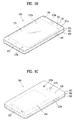
- the mobile terminal 100 is described with reference to a bar-type terminal body.
- the mobile terminal 100 may alternatively be implemented in any of a variety of different configurations. Examples of such configurations include watch-type, clip-type, glasses-type, or as a folder-type, flip-type, slide-type, swing-type, and swivel-type in which two and more bodies are combined with each other in a relatively movable manner, and combinations thereof. Discussion herein will often relate to a particular type of mobile terminal (for example, bar-type, watch-type, glasses-type, and the like). However, such teachings with regard to a particular type of mobile terminal will generally apply to other types of mobile terminals as well.
- the display unit 151 is shown located on the front side of the terminal body to output information. As illustrated, a window 151a of the display unit 151 may be mounted to the front case 101 to form the front surface of the terminal body together with the front case 101.
- electronic components may also be mounted to the rear case 102.
- electronic components include a detachable battery 191, an identification module, a memory card, and the like.
- Rear cover 103 is shown covering the electronic components, and this cover may be detachably coupled to the rear case 102. Therefore, when the rear cover 103 is detached from the rear case 102, the electronic components mounted to the rear case 102 are externally exposed.
- the mobile terminal 100 may include a waterproofing unit for preventing introduction of water into the terminal body.
- the waterproofing unit may include a waterproofing member which is located between the window 151a and the front case 101, between the front case 101 and the rear case 102, or between the rear case 102 and the rear cover 103, to hermetically seal an inner space when those cases are coupled.
- FIGS. 1B and 1C depict certain components as arranged on the mobile terminal. However, it is to be understood that alternative arrangements are possible and within the teachings of the instant disclosure. Some components may be omitted or rearranged.
- the first manipulation unit 123a may be located on another surface of the terminal body
- the second audio output module 152b may be located on the side surface of the terminal body.
- the display unit 151 may be implemented using two display devices, which can implement the same or different display technology. For example, a plurality of the display units 151 may be arranged on one side, either spaced apart from each other, or these devices may be integrated, or these devices may be arranged on different surfaces.
- the display unit 151 may also include a touch sensor which senses a touch input received at the display unit.
- the touch sensor may be configured to sense this touch and the controller 180, for example, may generate a control command or other signal corresponding to the touch.
- the content which is input in the touching manner may be a text or numerical value, or a menu item which can be indicated or designated in various modes.
- the optical output module 154 can be configured to output light for indicating an event generation. Examples of such events include a message reception, a call signal reception, a missed call, an alarm, a schedule notice, an email reception, information reception through an application, and the like.
- the controller can control the optical output unit 154 to stop the light output.
- the first and second manipulation units 123a and 123b are examples of the user input unit 123, which may be manipulated by a user to provide input to the mobile terminal 100.
- the first and second manipulation units 123a and 123b may also be commonly referred to as a manipulating portion, and may employ any tactile method that allows the user to perform manipulation such as touch, push, scroll, or the like.
- the first and second manipulation units 123a and 123b may also employ any non-tactile method that allows the user to perform manipulation such as proximity touch, hovering, or the like.
- Some implementations include the rear input unit may implement some or all of the functionality of the first manipulation unit 123a in the rear input unit. As such, in situations where the first manipulation unit 123a is omitted from the front side, the display unit 151 can have a larger screen.
- a flash 124 is shown adjacent to the second camera 121b.
- the flash 124 may illuminate the subject.
- At least one antenna for wireless communication may be located on the terminal body.
- the antenna may be installed in the terminal body or formed by the case.
- an antenna which configures a part of the broadcast receiving module 111 may be retractable into the terminal body.
- an antenna may be formed using a film attached to an inner surface of the rear cover 103, or a case that includes a conductive material.
- the rear cover 103 is shown coupled to the rear case 102 for shielding the battery 191, to prevent separation of the battery 191, and to protect the battery 191 from an external impact or from foreign material.
- the rear case 103 may be detachably coupled to the rear case 102.
- An accessory for protecting an appearance or assisting or extending the functions of the mobile terminal 100 can also be provided on the mobile terminal 100.
- a cover or pouch for covering or accommodating at least one surface of the mobile terminal 100 may be provided.
- the cover or pouch may cooperate with the display unit 151 to extend the function of the mobile terminal 100.
- a touch pen for assisting or extending a touch input to a touch screen is another example of the accessory.
- the controller 180 activates the camera 121 and is then able to control a preview image, which is inputted through the camera 121, to be outputted through the display unit 151 [S202].
- the controller 180 may activate the camera 121 in response to a user input for running a camera application, a user input for selecting a photo to take through the camera 121 as an image to be attached to a message, or the like.
- the preview image means an image inputted through the camera 121 before taking a photo. Hence, a user is able to set up a photography composition and a focus target by watching the preview image.
- the controller 180 can make a request for a name information of the prescribed object to a server.
- the server extracts the name information indicating the corresponding object based on the received data and is then able to provide the extracted name information to the mobile terminal.
- the preset condition may include one of a condition that a prescribed time expires in a state of focusing on a prescribed object, a condition that a user input of touching a focused object is received, a condition that a prescribed voice command is inputted in a state of focusing on a prescribed object, a condition that a camera zooms in or out in a state of focusing on a prescribed object, and the like.
- the controller 180 can control a name of the object to be outputted [S204]. Moreover, the controller 180 triggers a photo taking and is also able to control a new shot button (hereinafter named 'recognition mode shot button'), which is provided to save a taken photo and the information on the prescribed object together in a manner that the taken photo and the corresponding information are linked to each other, to be additionally outputted, simultaneously [S204].
- 'recognition mode shot button' a new shot button
- FIG. 3 illustrates an example of a mobile terminal outputting a name of an object.
- the controller 180 can control a preview image inputted through the camera 121 to be displayed. At least one or more buttons related to the settings of the camera 121 can be outputted in a manner of overlaying the preview image. For example, as shown in FIG. 3 (a) , a shot button 302 for triggering a photo taking, a video mode button 304 for switching to a video shot mode, an end button 306 for deactivating the camera 121, a preview icon 308 for displaying a preview of an already taken photo and the like are outputted.
- the controller 180 can control the camera 121 to focus on the touched point. For example, if a touch input of touching a glass bottle 320 in the preview image shown in FIG. 3 (a) is received, the controller 180 can control a focal distance of the camera 121 to focus on the touched glass bottle 320.
- the controller 180 can make a request for a name information on the focused prescribed object to a server.
- a focus target is changed or a photography composition is changed due to a movement of the mobile terminal over a prescribed distance or a rotation of the mobile terminal over a prescribed angle
- a prescribed time can be counted again from a timing point of focusing on a new object or a timing point of changing a composition.
- the controller 180 can control a feedback, which is provided to indicate that the information on the object will be outputted, to be outputted.
- the output of the feedback may have one of the types such as a sound output, a vibration output, a light output and the like.
- the controller 180 can control the information on the prescribed object to be outputted in a manner of overlaying the preview image. For example, referring to FIG. 3 (b) , a popup window 330, which indicates that the name of the focused object is 'ABC COFFEE', is outputted.
- an existing shot button is divided into two equal parts including a left region and a right region. Subsequently, the left region of the button may be assigned for the existing shot button 302 (e.g., a button for simply triggering a photo taking) and the right region of the button may be assigned for a recognition mode shot button 312 (e.g., a button for commanding to save a taken photo and an information on a prescribed object together in a manner of them to each other).
- the existing shot button 302 e.g., a button for simply triggering a photo taking
- a recognition mode shot button 312 e.g., a button for commanding to save a taken photo and an information on a prescribed object together in a manner of them to each other.
- the controller 180 may output a new recognition mode shot button over the preview image separately from the existing shot button.
- FIG. 3 (b) shows that the existing shot button and the recognition mode shot button are simultaneously outputted
- the controller 180 may control the recognition mode shot button to be outputted only in a manner of replacing the existing shot button.
- the controller 180 can make a request for information related to the object to the server.
- the server extracts the image data of the object or the related information matching the name of the object and is then able to provide the user with the extracted image data or the extracted information.
- the controller 180 can control the related information of the object to be outputted [S206].
- the related information of the prescribed object may vary depending on a type of the prescribed object.
- the prescribed object related information received from the server may include a price of the product, an address to access a webpage (e.g., a webpage for displaying a search result using a product name as a keyword at a portal site, a home page of a product manufacturer, a home page of the product, etc.) for the product, a purchase information of the product, a product comment, instructions of the product, and the like.
- the prescribed object related information may include a location information on an object located place, a description of the object, an address to access a webpage for the object (e.g., a webpage for displaying a search result using a name of the building or sculpture as a keyword at a portal site, etc.), a purchase information of a product (e.g.., a tour product linked to a corresponding area, etc.) related to a corresponding area, and the like.
- a location information on an object located place e.g., a description of the object
- an address to access a webpage for the object e.g., a webpage for displaying a search result using a name of the building or sculpture as a keyword at a portal site, etc.
- a purchase information of a product e.g., a tour product linked to a corresponding area, etc.
- the focused object in the preview image includes a product.
- information related to the product is outputted on the preview image.
- the object is a target for identifying a person or place.
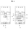
- FIG. 4 illustrates an example mobile terminal outputting information related to an object.
- the controller 180 can control information related to an object to be outputted. For example, if a popup window 410 indicating a name of an object is touched [e.g., FIG. 4 (a) ], the controller 180 can control a tab menu, which is provided to provide the object related information, to be outputted [e.g., FIG. 4 (b) ].
- a first tab 420 is provided to display a message for describing an object.
- a message window 425 including a message for describing the object e.g., a message for describing a product
- a translation button 428 for translating the description of the object may be additionally outputted to the message window 425. If the translation button 428 is touched, the controller 180 translates the description of the object into a preset language and then outputs the translated description. Alternatively, the controller 180 translates the description of the object into a language selected by a user and then outputs the translated description.
- the controller 180 can control a more quantity of a message for describing the object to be outputted in response to a touch input of touching the message window 425. In doing so, the controller 180 partitions the display unit 151 into two regions, controls a preview image to be outputted to one of the two regions as it is, and also controls the message for describing the object to be outputted to the other.
- a second tab 430 is provided to add a product corresponding to an object to a wish list. If the second tab 430 is touched, the controller 180 adds the product corresponding to the object to the wish list and is also able to control a message window including a product list included in the wish list to be outputted.
- the wish list may mean a list at which products desired to be purchased by a user are registered already. Through the wish list, the user can quickly purchase a desired product in the future.
- the controller 180 can control a more quantity of the wish list t to be outputted in response to a touch input of touching the message window. In doing so, the controller 180 partitions the display unit 151 into two regions, controls a preview image to be outputted to one of the two regions as it is, and also controls the wish list to be outputted to the other.
- a third tab 440 is provided to access a website related to an object. If the third tab 440 is selected, the controller 180 runs a web browser and is also able to attempt to access an address of the website related to the object. In doing so, the controller 180 partitions the display unit 151 into two regions, controls a preview image to be outputted to one of the two regions as it is, and also controls the web browser to be outputted to the other.
- a fourth tab 450 is provided to purchase a product corresponding to an object. If the fourth tab 450 is selected, the controller 180 can move to a purchase page for purchasing the product corresponding to the object. And, a user is able to purchase the product corresponding to the object through the purchase page.
- the information related to the object includes one of a description of the object, a wish list, a website, and a purchase.
- Detailed information related to the object and the number of the outputted detailed items of information are non-limited by the described example. More or less detailed items of information may be outputted or a different kind of a detailed information may be provided.
- the detailed information tab can be scrolled to move in response to user's touch input (e.g., an input of dragging a pointer currently touching a row in which a tab is currently displayed).
- the controller 180 may stop outputting the existing shot button 460.
- the recognition mode shot button 470 may be displayed on the preview image only.
- the information on the object e.g., the name of the object, the object related information
- the recognition mode shot button can stop being outputted.
- the controller 180 can control the information on the prescribed object and the recognition mode shot button to be outputted.
- the controller 180 may control a name of an object and an information related to the object to be outputted simultaneously.
- the controller 180 can adjust an output type of an indicator indicating a state of the object depending on whether a product corresponding to the object is already added to a wish list or whether a purchase history of a product corresponding to the object exists.
- An output type of an indicator is described in detail with reference to the accompanying drawing as follows.
- FIG. 5 illustrates an example mobile terminal outputting an indicator.
- the controller 180 can control the name of the object to be outputted together with a first indicator 510.
- the controller 180 can control the name of the object to be outputted together with a second indicator 520.
- the controller 180 can control the name of the object to be outputted together with a third indicator 530.
- a user can recognize whether a product corresponding to the object is already added to a wish list, whether a purchase history of a product corresponding to the object exists, or the like easily and conveniently.
- the controller 180 can control a message window, which is provided to query whether to purchase a product corresponding to an object, to be outputted in consideration of user's intention to purchase (or, repurchase) the corresponding product.
- FIG. 6 illustrates an example mobile terminal outputting a message window for querying whether to purchase a product.
- the controller 180 can control a message window 620, which provides an information indicating that the corresponding product is included in the wish list and also queries whether to move to a purchase page, to be outputted [e.g., FIG. 6 (b) ].
- the controller 180 can enter the purchase page to purchase the corresponding product.
- the purchase page may include one of a webpage for purchasing the corresponding product, a price comparison page for comparing prices at one or more shopping sites of selling the corresponding product, a page for making a payment of a purchase amount of the corresponding product, and the like.
- a payment page for paying a purchase amount of the corresponding product is outputted.
- the controller 180 can control a message, which queries whether to purchase the corresponding product, to be outputted.
- a product corresponding to the object is not included in the wish list or a purchase history of a product corresponding to the object does not exist, if the count of inquiries of the corresponding product is equal to or greater than a preset count, a message for querying whether to purchase the corresponding product can be outputted.
- the controller 180 can output a message window querying whether to share the information of the corresponding product with a pre-registered person (or character) or a person (or character) selected by a user.
- FIG. 7 illustrates an example mobile terminal outputting a message window for querying whether to share a product.
- the controller 180 can control a message window 720, which provides an information indicating that the corresponding product is included in the wish list and also queries whether to share the information of the corresponding product with another user, to be outputted [e.g., FIG. 7 (b) ].
- the controller 180 can control a message composing screen, which is provided to compose a message to send to another user, to be outputted [e.g., FIG. 7 (c) ].
- the information e.g., a name of a product, a photo 750 of a product, etc.
- the photo 750 may be extracted from a preview image.
- a pre-registered person may be added as a recipient to a message recipient box 730.
- a user may manually set a recipient of the message.
- the controller 180 can automatically set a substance that is to be included in a text body of the message.
- the controller 180 can control a text matching a context to be automatically included in the text body of the message in consideration of the message, a previously saved schedule, a call history and the like.
- the controller 180 may control a text, which responds to the received message, to be inserted in the text body of the message or may control a text appropriate for a schedule to be inserted in the text body of the message in consideration of a future schedule.
- the controller 180 designates a most recently called person as a recipient in consideration of a call history and is also able to automatically configure a text substance, which is to be inserted in the text body of the message, in consideration of a message received from the person designated as the recipient or a schedule with the person designated as the recipient.
- the controller 180 may control a message 760, which requests to present a gift, to be inserted in a text body 740.
- the controller 180 may control a message, which indicates that the corresponding product will be provided as a gift, to be inserted in a text body 740.
- the controller 180 can control a message, which queries whether to share the corresponding product with another user, to be outputted.
- a product corresponding to the object is not included in the wish list or a purchase history of a product corresponding to the object does not exist, if the count of inquiries of the corresponding product is equal to or greater than a preset count, a message for querying whether to share the corresponding product can be outputted.
- the controller 180 can determine which one of the items of information related to the product corresponding to the object will be preferentially outputted.
- FIG. 8 illustrates an example mobile terminal adjusting an output sequence of information related to a product in accordance with a location of a mobile terminal.
- the controller 180 can output a tab menu configured in order of a product comment 802 of the product corresponding to the object, a shopping basket loading 804, a payment 806, a product information 808, and the like.
- a tab indicating the product comment in the tab menu is activated, a message window 810 including the product comment is outputted.
- the controller 180 can output a tab menu configured in order of a translation page 812 of translating a name and description of the product corresponding to the object, an address 814 to access a website related to the product, a wish list 816, a payment 816, and the like.
- a tab indicating the product information in the tab menu is activated, a message window 820 including the product information is outputted.
- the controller 180 can preferentially output a product comment. If the mobile terminal is located in a foreign country, the controller 180 can preferentially output a translation page of a product description. In particular, the controller 180 can adjust information, which is to be preferentially outputted, among the items of information related to a product in accordance with a location of the mobile terminal.
- the mobile terminal may determine which one of the items of information related to the product will be preferentially outputted through detection of language displayed on the product. For example, if a language written on a product is Korean, like the example shown in FIG. 8 (a) , the controller 180 can control a product comment of a product corresponding to a recognized object to be preferentially outputted.
- the controller 180 can control a product information of a product corresponding to a recognized object to be preferentially outputted.
- information of describing a product is provided in user's mother language. For example, if a user is a Korean, the description of a product corresponding to a recognized object may be preferably outputted in Korean.
- the controller 180 can automatically output the received product description in a manner of translating the received product description into a first language. For example, if a product description received from a server is written in English, the controller 180 can automatically output the received product description in a manner of translating the received product description into Korean.
- the controller 180 outputs the received product description as it is and is also able to control the currently outputted product description to be outputted in a manner of being translated into another language in response to a user input.
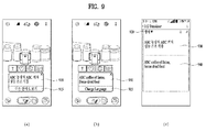
- FIG. 9 illustrates an example mobile terminal outputting a translated product description.
- the controller 180 can output a product description received from a server.
- a translation button 915 for translating a description of a product can be included in a message window 910 containing the product description. If the translation button 915 is touched, referring to FIG. 9 (b) , the controller 180 can control a translation text, which is created from translating the product description into a preset language, to be outputted through the message window 910.
- the controller 180 can control a setting screen, which is provided to set a translation language, to be outputted. For example, if a long touch input of touching the translation button over a prescribed time is received, referring to FIG. 9 (c) , the controller 180 can control a setting screen, which is provided to set a translation language, to be outputted.
- a pre-translation product description 930 a translation language setting button 920 for setting a translation language
- a translated product description 940 translated into the set translation language are included in the setting screen.
- a user is able to set a translation language through the button 920 for setting the translation language.
- the controller 180 can take a photo through the camera 121 [S208]. Moreover, the controller 180 can control the description of the focused object to be saved in a manner of being linked to the taken photo [S208].
- the controller 180 can control a photo taken through the recognition mode shot button to be displayed in a manner of being identifiable from a photo taken through a normal shot button.
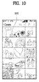
- FIG. 10 illustrates an example mobile terminal example of displaying a photo taken through a recognition mode shot button identifiably from a photo taken through a normal shot button.
- the controller 180 can control an indicator 1010, which indicates that a photo is taken through a recognition mode shot button, to be outputted over the photo taken through the recognition mode shot button in a photo shot list.
- an indicator 1010 which indicates that a photo is taken through a recognition mode shot button, to be outputted over the photo taken through the recognition mode shot button in a photo shot list.
- a user may recognize whether the corresponding photo is taken through the recognition mode shot button or the normal shot button.
- an indicator is used as a visual element for identifying a photo taken through a normal shot button and a photo taken through a recognition mode shot button from each other.
- a photo taken through a normal shot button and a photo taken through a recognition mode shot button may be displayed in a manner of being identifiable from each other based on at least one of an outline of a photo, a display of a text over a photo, a size of a photo in a list, and the like.
- the controller 180 can save a photo taken through a normal shot button and a photo taken through a recognition mode shot button to separate folders, respectively.
- a photo taken through a normal shot button may be saved to a first folder in a gallery, while a photo taken through a recognition mode shot button may be saved to a second folder in the gallery.
- the controller 180 displays the taken photo and is also able to control information on an object (e.g., a focused object at the time of photographing) contained in the photo to be outputted.
- an object e.g., a focused object at the time of photographing
- FIG. 11 illustrates an example mobile terminal outputting a photo taken through a recognition mode shot button.
- the controller 180 can output the selected photo through the display unit 151.
- the controller 180 can control an information 1120 (e.g., information on a focused object at the time of photographing) on an object linked to the selected photo to be outputted in a manner of overlaying the corresponding photo.
- an information 1120 e.g., information on a focused object at the time of photographing
- a message window 1120 containing a description of the object on the photo is outputted.
- the controller 180 when the controller 180 outputs a photo taken through a recognition mode shot button, the controller 180 can control information related to an object contained in the corresponding photo to be outputted together. Through this, a user can read and view the information of the object contained in the photo easily and conveniently.
- the photo and the information on an object linked to the photo are simultaneously outputted.
- the controller 180 can control information on the object to be outputted.
- a recognition mode shot button is additionally outputted. Moreover, if the recognition mode shot button is touched, a photo is taken and an information on the object is also saved in a manner of being linked to the taken photo.
- the controller 180 takes a photo and may be then able to determine whether to save information on an object in a manner of linking the information to the taken photo.
- the controller 180 takes a photo but may not save information on an object in a manner of linking the information to the taken photo.
- the controller 180 taken a photo and is also able to save information on an object in a manner of linking the information to the taken photo.
- the controller 180 can determine whether to save information on an object in a manner of linking the information to a taken photo. In doing so, the first touch input and the second touch input can be distinguished from each other by at least one of a shot button touched duration, a shot button touch count, the number of pointers touching a shot button, and the like.
- the subject matter described above can be implemented in a program recorded medium as computer-readable codes.
- the computer-readable media may include all kinds of recording devices in which data readable by a computer system are stored.
- the computer-readable media may include ROM, RAM, CD-ROM, magnetic tapes, floppy discs, optical data storage devices, and the like for example and also include carrier-wave type implementations (e.g., transmission via Internet).
- the computer may include the controller 180 of the terminal.
- the subject matter described in this application provides a mobile terminal and controlling method thereof, whereby information on an object included in a preview image of a camera can be outputted.
- the subject matter described in this application provides a mobile terminal and controlling method thereof, whereby a taken photo and an information on an object can be saved in a manner of being linked to each other.
- the processor-readable media may include all kinds of recording devices in which data readable by a processor are stored.
- the processor-readable media may include ROM, RAM, CD-ROM, magnetic tapes, floppy discs, optical data storage devices, and the like for example and also include carrier-wave type implementations (e.g., transmission via Internet).
Landscapes
- Engineering & Computer Science (AREA)
- Signal Processing (AREA)
- Multimedia (AREA)
- Human Computer Interaction (AREA)
- Physics & Mathematics (AREA)
- Business, Economics & Management (AREA)
- Theoretical Computer Science (AREA)
- General Physics & Mathematics (AREA)
- Accounting & Taxation (AREA)
- Finance (AREA)
- Computer Networks & Wireless Communication (AREA)
- Strategic Management (AREA)
- General Business, Economics & Management (AREA)
- Marketing (AREA)
- Economics (AREA)
- Development Economics (AREA)
- Mathematical Physics (AREA)
- Data Mining & Analysis (AREA)
- Databases & Information Systems (AREA)
- General Engineering & Computer Science (AREA)
- Telephone Function (AREA)
- User Interface Of Digital Computer (AREA)
- Studio Devices (AREA)
Applications Claiming Priority (1)
| Application Number | Priority Date | Filing Date | Title |
|---|---|---|---|
| KR1020150121824A KR20170025413A (ko) | 2015-08-28 | 2015-08-28 | 이동 단말기 및 그 제어 방법 |
Publications (2)
| Publication Number | Publication Date |
|---|---|
| EP3136708A2 true EP3136708A2 (de) | 2017-03-01 |
| EP3136708A3 EP3136708A3 (de) | 2017-06-07 |
Family
ID=55521461
Family Applications (1)
| Application Number | Title | Priority Date | Filing Date |
|---|---|---|---|
| EP16157265.6A Withdrawn EP3136708A3 (de) | 2015-08-28 | 2016-02-25 | Mobiles endgerät und steuerungsverfahren dafür |
Country Status (4)
| Country | Link |
|---|---|
| US (1) | US9955080B2 (de) |
| EP (1) | EP3136708A3 (de) |
| KR (1) | KR20170025413A (de) |
| CN (1) | CN106488002B (de) |
Cited By (1)
| Publication number | Priority date | Publication date | Assignee | Title |
|---|---|---|---|---|
| WO2018200284A1 (en) * | 2017-04-27 | 2018-11-01 | GICSOFT, Inc. | Media sharing based on identified physical objects |
Families Citing this family (13)
| Publication number | Priority date | Publication date | Assignee | Title |
|---|---|---|---|---|
| CN112732147B (zh) | 2016-05-18 | 2025-02-21 | 苹果公司 | 在图形消息传送用户界面中应用确认选项 |
| US10592098B2 (en) * | 2016-05-18 | 2020-03-17 | Apple Inc. | Devices, methods, and graphical user interfaces for messaging |
| US10368208B2 (en) | 2016-06-12 | 2019-07-30 | Apple Inc. | Layers in messaging applications |
| US11785161B1 (en) | 2016-06-20 | 2023-10-10 | Pipbin, Inc. | System for user accessibility of tagged curated augmented reality content |
| US20180300916A1 (en) * | 2017-04-14 | 2018-10-18 | Facebook, Inc. | Prompting creation of a networking system communication with augmented reality elements in a camera viewfinder display |
| CN107395846B (zh) * | 2017-07-07 | 2019-07-30 | 珠海格力电器股份有限公司 | 一种语音与相册关联方法及其装置、用户终端 |
| CN113227940A (zh) | 2018-11-09 | 2021-08-06 | 贝克曼库尔特有限公司 | 具有选择性数据提供的服务眼镜 |
| KR20200079209A (ko) * | 2018-12-24 | 2020-07-02 | 엘지전자 주식회사 | 이동 단말기 및 그 제어 방법 |
| US11055361B2 (en) | 2019-01-07 | 2021-07-06 | Microsoft Technology Licensing, Llc | Extensible framework for executable annotations in electronic content |
| EP3956858B1 (de) | 2019-04-18 | 2025-12-03 | Beckman Coulter, Inc. | Sicherung der daten von objekten in einer laborumgebung |
| KR102707773B1 (ko) * | 2019-08-06 | 2024-09-20 | 삼성전자 주식회사 | 객체에 대응하는 그래픽 요소 표시 방법 및 장치 |
| CN110913141B (zh) * | 2019-11-29 | 2021-09-21 | 维沃移动通信有限公司 | 一种视频显示方法、电子设备以及介质 |
| US12061842B2 (en) * | 2022-04-04 | 2024-08-13 | Snap Inc. | Wearable device AR object voice-based interaction |
Citations (1)
| Publication number | Priority date | Publication date | Assignee | Title |
|---|---|---|---|---|
| US20130188886A1 (en) * | 2011-12-06 | 2013-07-25 | David Petrou | System and method of identifying visual objects |
Family Cites Families (18)
| Publication number | Priority date | Publication date | Assignee | Title |
|---|---|---|---|---|
| JP4121974B2 (ja) * | 2004-03-26 | 2008-07-23 | 富士フイルム株式会社 | 画像撮影システムおよび画像撮影方法 |
| JP4636064B2 (ja) * | 2007-09-18 | 2011-02-23 | ソニー株式会社 | 画像処理装置および画像処理方法、並びにプログラム |
| KR101778135B1 (ko) * | 2009-08-24 | 2017-09-14 | 삼성전자주식회사 | 오브젝트 정보 제공방법 및 이를 적용한 촬영장치 |
| KR100957575B1 (ko) * | 2009-10-01 | 2010-05-11 | (주)올라웍스 | 단말기의 움직임 또는 자세에 기초하여 비주얼 서치를 수행하기 위한 방법, 단말기 및 컴퓨터 판독 가능한 기록 매체 |
| US20110213664A1 (en) * | 2010-02-28 | 2011-09-01 | Osterhout Group, Inc. | Local advertising content on an interactive head-mounted eyepiece |
| KR101643869B1 (ko) * | 2010-05-06 | 2016-07-29 | 엘지전자 주식회사 | 휴대 단말기 및 그 동작 방법 |
| JP2012065263A (ja) * | 2010-09-17 | 2012-03-29 | Olympus Imaging Corp | 撮影機器 |
| US8890896B1 (en) * | 2010-11-02 | 2014-11-18 | Google Inc. | Image recognition in an augmented reality application |
| KR101739378B1 (ko) * | 2010-12-23 | 2017-05-24 | 삼성전자주식회사 | 디지털 영상 촬영 장치 및 이의 제어 방법 |
| KR101495790B1 (ko) * | 2010-12-28 | 2015-02-25 | 주식회사 케이티 | 이동 단말기 및 이동 단말기에서의 화면 표시 제어 방법 |
| US20150012426A1 (en) * | 2013-01-04 | 2015-01-08 | Visa International Service Association | Multi disparate gesture actions and transactions apparatuses, methods and systems |
| US9491368B2 (en) * | 2012-07-24 | 2016-11-08 | Nec Corporation | Information obtaining and viewing device, data processing method thereof, and non-transitory computer readable medium storing a program |
| EP2704039A3 (de) * | 2012-08-31 | 2014-08-27 | LG Electronics, Inc. | Mobiles Endgerät |
| RU2533445C2 (ru) * | 2012-10-02 | 2014-11-20 | ЭлДжи ЭЛЕКТРОНИКС ИНК. | Автоматическое распознавание и съемка объекта |
| US8866953B2 (en) * | 2013-03-20 | 2014-10-21 | Lg Electronics Inc. | Mobile device and method for controlling the same |
| US8704939B1 (en) * | 2013-03-20 | 2014-04-22 | Lg Electronics Inc. | Mobile device and method for controlling the same |
| KR102158691B1 (ko) * | 2014-01-08 | 2020-09-22 | 엘지전자 주식회사 | 이동 단말기 및 그 제어 방법 |
| KR20160019760A (ko) * | 2014-08-12 | 2016-02-22 | 엘지전자 주식회사 | 이동 단말기 및 그것의 제어방법 |
-
2015
- 2015-08-28 KR KR1020150121824A patent/KR20170025413A/ko not_active Ceased
-
2016
- 2016-02-25 EP EP16157265.6A patent/EP3136708A3/de not_active Withdrawn
- 2016-04-15 US US15/099,852 patent/US9955080B2/en active Active
- 2016-05-03 CN CN201610285715.5A patent/CN106488002B/zh not_active Expired - Fee Related
Patent Citations (1)
| Publication number | Priority date | Publication date | Assignee | Title |
|---|---|---|---|---|
| US20130188886A1 (en) * | 2011-12-06 | 2013-07-25 | David Petrou | System and method of identifying visual objects |
Cited By (1)
| Publication number | Priority date | Publication date | Assignee | Title |
|---|---|---|---|---|
| WO2018200284A1 (en) * | 2017-04-27 | 2018-11-01 | GICSOFT, Inc. | Media sharing based on identified physical objects |
Also Published As
| Publication number | Publication date |
|---|---|
| KR20170025413A (ko) | 2017-03-08 |
| EP3136708A3 (de) | 2017-06-07 |
| US20170064207A1 (en) | 2017-03-02 |
| US9955080B2 (en) | 2018-04-24 |
| CN106488002A (zh) | 2017-03-08 |
| CN106488002B (zh) | 2019-07-23 |
Similar Documents
| Publication | Publication Date | Title |
|---|---|---|
| US9955080B2 (en) | Image annotation | |
| US10056082B2 (en) | Mobile terminal and method of controlling therefor | |
| US9787890B2 (en) | Mobile terminal and method of controlling the same | |
| US9705828B2 (en) | Mobile terminal and controlling method thereof | |
| US10739940B2 (en) | Mobile terminal for generating a folder by using icons corresponding to applications and method of controlling the same | |
| US10101876B2 (en) | User interface for a mobile device with lateral display surfaces | |
| EP2999128B1 (de) | Mobiles endgerät und steuerungsverfahren dafür | |
| US9841891B2 (en) | Mobile terminal and method of controlling the same | |
| US10185492B2 (en) | Mobile terminal and method for controlling the same | |
| EP2988201A1 (de) | Mobiles Endgerät und Verfahren zur Steuerung davon | |
| US9864486B2 (en) | Mobile terminal and controlling method thereof | |
| EP3531260A1 (de) | Mobiles endgerät und verfahren zum betrieb davon | |
| US9438723B2 (en) | Providing various functions to a mobile device using a cover having an opening formed therein | |
| US10468021B2 (en) | Mobile terminal and method for controlling the same | |
| US10769413B2 (en) | Mobile terminal and control method thereof | |
| US10645141B2 (en) | Mobile terminal and method for controlling the same | |
| US20170277399A1 (en) | Mobile terminal and controlling method thereof | |
| US20160080540A1 (en) | Mobile terminal and method for controlling the same | |
| US10455389B2 (en) | Mobile terminal and control method therefor | |
| US20170228131A1 (en) | Mobile terminal and method for controlling the same | |
| US10360480B2 (en) | Terminal device and control method | |
| US10671992B2 (en) | Terminal and controlling method thereof | |
| EP3171579A2 (de) | Mobile vorrichtung und verfahren zur steuerung davon | |
| US20180052647A1 (en) | Electronic device and method for controlling the same | |
| US20160171006A1 (en) | Mobile terminal and method for controlling the same |
Legal Events
| Date | Code | Title | Description |
|---|---|---|---|
| PUAI | Public reference made under article 153(3) epc to a published international application that has entered the european phase |
Free format text: ORIGINAL CODE: 0009012 |
|
| STAA | Information on the status of an ep patent application or granted ep patent |
Free format text: STATUS: THE APPLICATION HAS BEEN PUBLISHED |
|
| AK | Designated contracting states |
Kind code of ref document: A2 Designated state(s): AL AT BE BG CH CY CZ DE DK EE ES FI FR GB GR HR HU IE IS IT LI LT LU LV MC MK MT NL NO PL PT RO RS SE SI SK SM TR |
|
| AX | Request for extension of the european patent |
Extension state: BA ME |
|
| AK | Designated contracting states |
Kind code of ref document: A3 Designated state(s): AL AT BE BG CH CY CZ DE DK EE ES FI FR GB GR HR HU IE IS IT LI LT LU LV MC MK MT NL NO PL PT RO RS SE SI SK SM TR |
|
| AX | Request for extension of the european patent |
Extension state: BA ME |
|
| RIC1 | Information provided on ipc code assigned before grant |
Ipc: H04M 1/725 20060101ALI20170502BHEP Ipc: G06F 17/30 20060101ALI20170502BHEP Ipc: H04N 5/232 20060101AFI20170502BHEP Ipc: G06K 9/00 20060101ALI20170502BHEP |
|
| PUAL | Search report despatched |
Free format text: ORIGINAL CODE: 0009013 |
|
| STAA | Information on the status of an ep patent application or granted ep patent |
Free format text: STATUS: REQUEST FOR EXAMINATION WAS MADE |
|
| 17P | Request for examination filed |
Effective date: 20171026 |
|
| RBV | Designated contracting states (corrected) |
Designated state(s): AL AT BE BG CH CY CZ DE DK EE ES FI FR GB GR HR HU IE IS IT LI LT LU LV MC MK MT NL NO PL PT RO RS SE SI SK SM TR |
|
| STAA | Information on the status of an ep patent application or granted ep patent |
Free format text: STATUS: EXAMINATION IS IN PROGRESS |
|
| 17Q | First examination report despatched |
Effective date: 20191029 |
|
| GRAP | Despatch of communication of intention to grant a patent |
Free format text: ORIGINAL CODE: EPIDOSNIGR1 |
|
| STAA | Information on the status of an ep patent application or granted ep patent |
Free format text: STATUS: GRANT OF PATENT IS INTENDED |
|
| RIC1 | Information provided on ipc code assigned before grant |
Ipc: H04N 5/232 20060101ALN20220120BHEP Ipc: G06Q 30/06 20120101ALI20220120BHEP Ipc: G06V 20/20 20220101ALI20220120BHEP Ipc: H04M 1/72403 20210101AFI20220120BHEP |
|
| INTG | Intention to grant announced |
Effective date: 20220218 |
|
| STAA | Information on the status of an ep patent application or granted ep patent |
Free format text: STATUS: THE APPLICATION IS DEEMED TO BE WITHDRAWN |
|
| 18D | Application deemed to be withdrawn |
Effective date: 20220629 |