EP3136626B1 - Procédés et dispositif de mesure de la puissance d'un signal - Google Patents
Procédés et dispositif de mesure de la puissance d'un signal Download PDFInfo
- Publication number
- EP3136626B1 EP3136626B1 EP16192589.6A EP16192589A EP3136626B1 EP 3136626 B1 EP3136626 B1 EP 3136626B1 EP 16192589 A EP16192589 A EP 16192589A EP 3136626 B1 EP3136626 B1 EP 3136626B1
- Authority
- EP
- European Patent Office
- Prior art keywords
- signal
- power
- received power
- cell
- measuring
- Prior art date
- Legal status (The legal status is an assumption and is not a legal conclusion. Google has not performed a legal analysis and makes no representation as to the accuracy of the status listed.)
- Active
Links
- 238000000691 measurement method Methods 0.000 title description 26
- 238000000034 method Methods 0.000 claims description 83
- 230000001427 coherent effect Effects 0.000 claims description 11
- 238000012935 Averaging Methods 0.000 claims description 9
- 230000008859 change Effects 0.000 claims description 5
- 238000005259 measurement Methods 0.000 description 39
- 238000004891 communication Methods 0.000 description 15
- 238000001514 detection method Methods 0.000 description 9
- 238000012545 processing Methods 0.000 description 7
- 230000009471 action Effects 0.000 description 4
- 230000010267 cellular communication Effects 0.000 description 4
- 230000006870 function Effects 0.000 description 4
- 230000008569 process Effects 0.000 description 4
- 238000013459 approach Methods 0.000 description 3
- 125000004122 cyclic group Chemical group 0.000 description 3
- 238000001914 filtration Methods 0.000 description 3
- 230000005540 biological transmission Effects 0.000 description 2
- 230000001413 cellular effect Effects 0.000 description 2
- 238000010586 diagram Methods 0.000 description 2
- 239000013307 optical fiber Substances 0.000 description 2
- 230000003595 spectral effect Effects 0.000 description 2
- 230000006978 adaptation Effects 0.000 description 1
- 239000000654 additive Substances 0.000 description 1
- 230000000996 additive effect Effects 0.000 description 1
- 230000001419 dependent effect Effects 0.000 description 1
- 238000005562 fading Methods 0.000 description 1
- 230000001771 impaired effect Effects 0.000 description 1
- 230000007774 longterm Effects 0.000 description 1
- 230000003287 optical effect Effects 0.000 description 1
- 238000009877 rendering Methods 0.000 description 1
- 239000004065 semiconductor Substances 0.000 description 1
- 238000001228 spectrum Methods 0.000 description 1
- 230000003068 static effect Effects 0.000 description 1
- 230000001960 triggered effect Effects 0.000 description 1
Images


Classifications
-
- H—ELECTRICITY
- H04—ELECTRIC COMMUNICATION TECHNIQUE
- H04L—TRANSMISSION OF DIGITAL INFORMATION, e.g. TELEGRAPHIC COMMUNICATION
- H04L25/00—Baseband systems
- H04L25/02—Details ; arrangements for supplying electrical power along data transmission lines
- H04L25/0202—Channel estimation
- H04L25/0224—Channel estimation using sounding signals
-
- H—ELECTRICITY
- H04—ELECTRIC COMMUNICATION TECHNIQUE
- H04B—TRANSMISSION
- H04B17/00—Monitoring; Testing
- H04B17/30—Monitoring; Testing of propagation channels
- H04B17/309—Measuring or estimating channel quality parameters
- H04B17/318—Received signal strength
- H04B17/327—Received signal code power [RSCP]
-
- H—ELECTRICITY
- H04—ELECTRIC COMMUNICATION TECHNIQUE
- H04B—TRANSMISSION
- H04B17/00—Monitoring; Testing
- H04B17/30—Monitoring; Testing of propagation channels
- H04B17/309—Measuring or estimating channel quality parameters
- H04B17/336—Signal-to-interference ratio [SIR] or carrier-to-interference ratio [CIR]
-
- H—ELECTRICITY
- H04—ELECTRIC COMMUNICATION TECHNIQUE
- H04L—TRANSMISSION OF DIGITAL INFORMATION, e.g. TELEGRAPHIC COMMUNICATION
- H04L25/00—Baseband systems
- H04L25/02—Details ; arrangements for supplying electrical power along data transmission lines
- H04L25/0202—Channel estimation
- H04L25/0204—Channel estimation of multiple channels
-
- H—ELECTRICITY
- H04—ELECTRIC COMMUNICATION TECHNIQUE
- H04L—TRANSMISSION OF DIGITAL INFORMATION, e.g. TELEGRAPHIC COMMUNICATION
- H04L5/00—Arrangements affording multiple use of the transmission path
- H04L5/0001—Arrangements for dividing the transmission path
- H04L5/0003—Two-dimensional division
- H04L5/0005—Time-frequency
- H04L5/0007—Time-frequency the frequencies being orthogonal, e.g. OFDM(A), DMT
Definitions
- This invention relates to radio communication systems and more particularly to measurement of received signal power in such systems.
- OFDM orthogonal frequency division multiplex
- 3G LTE Third Generation Long Term Evolution
- 3GPP Third Generation Partnership Project
- the 3G LTE specifications can be seen as an evolution of the current WCDMA specifications also promulgated by the 3GPP.
- a 3G LTE system will use OFDM as a multiple access technique (called OFDMA) in the downlink (DL) from system nodes to user equipments (UEs), will operate with channel bandwidths ranging from 1.25 megahertz (MHz) to 20 MHz, and will support data rates up to 100 megabits per second (Mb/s) on the largest-bandwidth channels.
- OFDMA OFDMA
- DL downlink
- UEs user equipments
- Mb/s megabits per second
- 3G LTE systems are expected to provide low-data-rate services, such as speech.
- TCP/IP transmission control protocol/internet protocol
- VoIP voice-over-IP
- the data stream to be transmitted is portioned among a number of narrowband subcarriers that are transmitted in parallel.
- a resource block devoted to a particular UE is a particular number of particular subcarriers used for a particular period of time. Different groups of subcarriers can be used at different times for different users. Because each subcarrier is narrowband, each carrier experiences mainly flat fading, which makes it easier for a UE to demodulate each subcarrier.
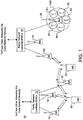
- FIG. 1 depicts a typical cellular communication system 10.
- Radio network controllers (RNCs) 12, 14 control various radio network functions, including for example radio access bearer setup, diversity handover, etc.
- each RNC directs calls to and from a UE, such as a mobile station (MS), mobile phone, or other remote terminal, via appropriate base station(s) (BSs), which communicate with each other through DL (or forward) and uplink (UL, or reverse) channels.
- BSs base station(s)
- FIG. 1 RNC 12 is shown coupled to BSs 16, 18, 20, and RNC 14 is shown coupled to BSs 22, 24, 26.
- Each BS, or Node B in 3G vocabulary, serves a geographical area that is divided into one or more cell(s).
- BS 26 is shown as having five antenna sectors S1-S5, which can be said to make up the cell of the BS 26, although a sector or other area served by signals from a BS can also be called a cell.
- a BS may use more than one antenna to transmit signals to a UE.
- the BSs are typically coupled to their corresponding RNCs by dedicated telephone lines, optical fiber links, microwave links, etc.
- the RNCs 12, 14 are connected with external networks such as the public switched telephone network (PSTN), the internet, etc. through one or more core network nodes, such as a mobile switching center (not shown) and/or a packet radio service node (not shown).
- PSTN public switched telephone network
- core network nodes such as a mobile switching center (not shown) and/or a packet radio service node (not shown).
- FIG. 1 the arrangement of functionalities depicted in FIG. 1 can be modified in 3G LTE and other communication systems.
- the functionality of the RNCs 12, 14 can be moved to the Node Bs 22, 24, 26, and other functionalities can be moved to other nodes in the network.
- a base station can use multiple transmit antennas to transmit information into a cell/sector/area, and those different transmit antennas can send respective, different pilot signals.
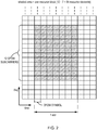
- FIG. 2 is a frequency-vs.-time plot showing an arrangement of DL subcarriers in an OFDM communication system, such as a 3G LTE system.
- a resource block includes twelve subcarriers spaced apart by fifteen kilohertz (kHz), which together occupy approximately 180 kHz in frequency and 0.5 millisecond (ms) in time, or one time slot.
- FIG. 2 shows each time slot including seven OFDM symbols, or resource elements (REs), each of which has a short (normal) cyclic prefix, although six OFDM symbols having long (extended) cyclic prefixes can also be used in a time slot.
- resource blocks can include various numbers of subcarriers for various periods of time.
- RSRP reference signals and symbols received power
- the RS, or pilots are transmitted from each Node B at known frequencies and time instants, and are used by UEs for synchronization and other purposes besides handover.
- Such reference signals and symbols are described for example in Section 7.1.1.2.2 of 3GPP Technical Report (TR) 25.814 V7.0.0, Physical Layer Aspects for Evolved Universal Terrestrial Radio Access (UTRA) (Release 7), June 2006 , and Sections 6.10 and 6.11 of 3GPP Technical Specification (TS) 36.211 V8.1.0, Physical Channels and Modulation (Release 8), November 2007 .
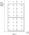
- RS are transmitted from each of possibly 1, 2, or 4 transmit antennas of a Node B on particular REs that can be conveniently represented on the frequency-vs.-time plane as depicted in FIG. 3 . It will be understood that the arrangement of FIG. 3 is just an example and that other arrangements can be used.
- FIG. 3 shows two successive time slots, indicated by the vertical solid lines, which can be called a sub-frame.
- the frequency range depicted in FIG. 3 includes about twenty-six subcarriers, only nine of which are explicitly indicated.
- RS transmitted by a first transmit (TX) antenna of a Node B are denoted R and by a possible second TX antenna in the node are denoted by S.
- R transmit
- S possible second TX antenna in the node
- RS are depicted as transmitted on every sixth subcarrier in OFDM symbol 0 and OFDM symbol 3 or 4 (depending on whether the symbols have long or short cyclic prefixes) in every slot.
- the RSs in symbols 3 or 4 are offset by 3 subcarriers relative to the RS in OFDM symbol 0, the first OFDM symbol in a slot.
- the artisan will understand that it is desirable for a UE to base its RSRP measurements on RS transmitted from all TX antennas used by a node for a cell. Nevertheless, the number of TX antennas used by a cell detected in a cell search procedure but not currently connected to the UE (which can be called "a detected neighboring cell") is typically not known in advance by the UE. As a result, the UE needs to determine the number of TX antennas "blindly", i.e., without receiving a special message informing the UE of that number. When signals transmitted by a cell are received by a UE with low signal-to-interference ratios (SIRs), the risk of blindly detecting an erroneous number of TX antennas is significant.
- SIRs signal-to-interference ratios
- Low SIR is a common situation for a detected neighboring cell because such a cell's signal power level at the UE is usually lower than the received power level of the serving cell. Due to the increased probability of a blind detection error, RSRP measurements based on an assumed second TX antenna in low SIR conditions are unreliable with a potentially large bias.
- FFT processing consumes time, power, and/or hardware resources that are limited in many UEs and increases the complexity of the signal-power-estimate processing in a UE, both of which render this solution undesirable.
- a UE typically assumes that the characteristics of the DL channel are constant over a number of subcarriers (i.e., the channel is constant with frequency) and over a number of OFDM symbols (i.e., the channel is constant in time). Based on that assumption, the UE estimates the RSRP by coherently averaging received symbols over such a "constant" group to get a channel estimate Hi for a subcarrier i, computes the square of the absolute value of the channel estimate
- such coherent averaging to estimate the RSRP can proceed as follows.
- the unreliability and potentially large bias of RSRP measurements based on an assumed second TX antenna in low SIR conditions can now be understood for the exemplary case of additive white Gaussian noise, i.e., a static channel impaired by only addition of wideband noise having a constant spectral density.
- the number N affects only the variance, not the bias of the estimate, as explained in U.S. Patent Application Publication No. US 2008/0101488 A1 by L. Wilhelmsson et al. for "Robust and Low-Complexity Combined Signal Power Estimation", for example.
- WO 2007/019171 discloses an approach for noise estimation.
- the approach includes to determine whether a received signal is Single Input Single Output (SISO) or Multiple Input Multiple Output (MIMO) based on a preamble. When a MIMO signal is present, one noise power vector is estimated per receiver.
- SISO Single Input Single Output
- MIMO Multiple Input Multiple Output
- WO 02/087106 discloses an approach for estimating signal-to-interference ratio (SIR) where estimation process is selected among two estimation processes (wideband and narrowband interference estimation processes) such that it is most suitable in view of characteristics of the received signal (data or speech).
- SIR signal-to-interference ratio
- the DL channel commonly suffers from delay spread and Doppler shift, and so the channel is not constant as typically assumed, leading again to increased probability of biassed RSRP measurement values.
- a known solution to this problem of varying DL channels is to use more advanced methods of estimating the channel and signal power (e.g., methods based on Wiener filtering). Like the FFT processing mentioned above, such more advanced methods are computationally intensive and need to be done on each detected neighboring cell, rendering this solution undesirable.
- a method of estimating a received power of at least one signal having a pattern known to the receiver, the signal having been transmitted by at least one antenna includes using a first method of measuring the received power based on the pattern, the first method generating a first sequence of first power estimates; determining whether a predetermined first event has occurred, wherein the determining step includes detecting by blind detection that the signal was transmitted by at least two antennas; and if the first event has occurred, changing to a second method of measuring the received power, the second method being different from the first method and generating a second sequence of second power estimates, wherein the second method of measuring the received power differs from the first method at least in that the second method generates the second sequence based on the patterns transmitted by the at least two antennas.
- an apparatus in a receiver for measuring a received power of at least one signal having a pattern known to the receiver, the signal having been transmitted by at least one antenna.
- the apparatus includes a channel estimator configured to generate channel estimates based on the pattern in the at least one signal; a power estimator configured to generate received signal power estimates based on the channel estimates; and a controller configured to determine which of a first method and a second estimating method is used by at least one of the channel estimator and the power estimator, wherein the controller determines which of the first and second methods is used based on blind detection whether the signal was transmitted by at least two antennas.
- the first and second methods are different and generate respective sequences of first and second power estimates and the second method differs from the first method at least in that the second method generates the second sequence based on the patterns transmitted by the at least two antennas.
- a computer-readable medium containing instructions that, when executed by the computer, cause the computer to carry out a method in a receiver of measuring a received power of at least one signal having a pattern known to the receiver, the signal having been transmitted by at least one antenna.
- the method includes using a first method of measuring the received power based on the pattern, the first method generating a first sequence of first power estimates; determining whether a predetermined first event has occurred, wherein the determining step includes detecting by blind detection that the signal was transmitted by at least two antennas; and if the first event has occurred, changing to a second method of measuring the received power, the second method being different from the first method and generating a second sequence of second power estimates and the second method of measuring the received power differs from the first method at least in that the second method generates the second sequence based on the patterns transmitted by the at least two antennas.
- the methods and apparatus for measuring received signal power for handover measurements are adapted based on the estimated (measured) signal power level such that computationally intensive channel and signal-power estimation methods are used only when necessary.
- a good trade-off between signal power measurement complexity and signal power measurement performance can be achieved.
- measurements are based on reference (pilot) symbols transmitted from only one TX antenna of a Node B when the received signal power (or SIR) is low.
- the measurements are based on an average (or sum) of reference symbols transmitted from at least two Node B TX antennas.
- the measurement method can be changed according to the measured (estimated) signal power (or SIR) level.
- a simple measurement method is used, e.g., a method of channel estimation based on simple averaging according to Eq. 3 above.
- the estimated power level is high, a more complicated measurement method is used.
- a received signal estimate S n,m est is generated for each received reference symbol RSn,m, and each such received signal estimate is generated by linear filtering of the neighboring RSs with filter coefficients a l-m,k-n that are a function of Doppler shift, delay spread, etc.
- the change to a more advanced measurement method can be based on an absolute signal level/threshold or alternatively on a relative signal level/threshold, where the relation for triggering a particular measurement method for a particular neighboring cell is based on the relative difference between the power (or SIR) of a neighboring cell and the power (or SIR) of the serving cell.
- the change is triggered only if the received power (or SIR) of less than a particular number of cells is measured using a more advanced method, in which case, the decision can be based on measurements using the second method.
- FIG. 4 is a flow chart of an improved measurement method in accordance with this invention.
- a UE is assumed to be connected to a serving cell (or equivalently to be camped on a cell in idle mode) in a 3G LTE communication system such as that depicted in FIG. 1 , but it will be appreciated, however, that this invention can be implemented in other communication systems.
- the UE carries out a specified cell search procedure, e.g., for determining neighboring cells to be used as potential handover candidates and for other purposes.
- the UE performs a received signal power (e.g., an RSRP) measurement using a first measurement method (step 404).
- a received signal power e.g., an RSRP
- step 406 If the measured signal power does not meet one or more particular conditions that in FIG. 4 are called Event A (No in step 406), the process flow returns and power measurement on the detected cell continues using the first measurement method. It will be understood that step 404 can be carried out repeatedly according to the specifications of the communication system. If the UE determines that Event A has occurred (Yes in step 406), the UE starts to do signal power measurements on the detected neighboring cell according to a second measurement method (step 408).
- the UE performs measurements according to the first measurement method again. Otherwise (No in step 410), the UE continues to use the second signal measurement method.
- the flow chart in FIG. 4 assumes only one detected new cell, but in general a UE can have a number of simultaneous detected neighboring cells for which RSRP measurements are made simultaneously or sequentially.
- Use of the first or second measurement methods can be chosen independently for each such cell, or use of the first or second measurement methods can be chosen based on whether the first or second methods has already been chosen for a selectable number of other detected neighboring cells.
- the selectable number can correspond to the processing load borne by the UE.
- the method depicted in FIG. 4 can be applied to measurements on the serving cell.
- FIG. 5 is a block diagram of a portion 500 of a UE that can implement the methods described above. It will be appreciated that the functional blocks depicted in FIG. 5 can be combined and re-arranged in a variety of equivalent ways, and that many of the functions can be performed by one or more suitably programmed digital signal processors.
- a UE receives a DL radio signal through an antenna 502 and typically down-converts the received radio signal to an analog baseband signal in a front end receiver (Fe RX) 504.
- the baseband signal is spectrally shaped by an analog filter 506 that has a bandwidth BWo, and the shaped baseband signal generated by the filter 506 is converted from analog to digital form by an analog-to-digital converter (ADC) 508.
- ADC analog-to-digital converter
- the digitized baseband signal is further spectrally shaped by a digital filter 510 that has a bandwidth BW sync , which corresponds to the bandwidth of synchronization signals or symbols included in the DL signal.
- the shaped signal generated by the filter 510 is provided to a cell search unit 512 that carries out one or more methods of searching for cells as specified for the particular communication system, e.g., 3G LTE. Typically, such methods involve detecting predetermined primary and/or secondary synchronization channel (P/S-SCH) signals in the received signal.
- P/S-SCH primary and/or secondary synchronization channel
- the digitized baseband signal is also provided by the ADC 508 to a digital filter 514 that has the bandwidth BWo, and the filtered digital baseband signal is provided to a processor 516 that implements an FFT or other suitable algorithm that generates a frequency-domain (spectral) representation of the baseband signal.
- the cell search unit 512 exchanges suitable timing signals with the processor 516 for each candidate cell, i.e., each cell whose signal power (e.g., RSRP) will be measured.
- the cell search unit 512 also provides cell identifications and REs corresponding to RSs for each candidate cell to a channel estimation unit 518, which also receives timing signals from the processor 516 and generates a channel estimate Hi, j for each of several subcarriers i and cells j.
- the unit 518 can generate the channel estimates according to either the first or the second estimation method as described above based on control signals provided by a control unit 520.
- the estimator 518 provides the channel estimates Hi to a symbol detector 522 and further processing in the UE (not shown), and also to a signal power estimation unit 524 that generates received signal power measurements (e.g., estimates of RSRP, received subcarrier power Si, SIR, etc.).
- the estimator 524 can generate such estimates in various ways, for example, based on Eq. 3 or on Eq. 5 above.
- the control unit 520 determines which estimation method is used by the estimator 518 and/or by the estimator 524 for measurements on the detected cell(s).
- the determinations by the control unit 520 can, as described above, be based on absolute signal power values, as well as on relative signal power values (relative to other detected/serving cells).
- the power estimates generated by the estimator 524 are typically also used in further signal processing in the UE.
- the RS from a first TX antenna is always transmitted (see FIG. 3 ), and so after a UE has detected a cell, RSRP measurements based on that one TX antenna can be done. Measuring RSRP based on one TX antenna can be considered as the first measurement method in the flowchart of FIG. 4 .
- the number of TX antennas in a cell is unknown to the UE and needs to be blindly detected.
- the received signal power of the cell is low relative to the sum of the received signal powers of other cells and noise (e.g., RSRP values that are -3 dB relative to the RSRP values for the strongest detected cell, which may be the serving cell)
- the accuracy of the blind detection method is poor.
- the TX antenna detection accuracy is good.
- Poor accuracy generally means that the probability of correct detection, i.e., that two TX antennas are detected when two antennas are used and one TX antenna is detected when one antenna is used, is below 0.8 or so, and good accuracy means that the probability of correct detection is at least about 0.9.
- the UE After a UE has detected a second TX antenna (see Event A in FIG. 4 ), the UE starts to do RSRP measurements based on both TX antennas. Measuring RSRP based on two (or more) TX antennas can be considered as the second measurement method in FIG. 4 .
- Event A can be arranged such that it indicates the UE has detected at least one second TX antenna for a cell and has measured that cell's RSRP as greater than a particular amount, e.g., -3 dB, relative to the RSRP measured for the strongest detected cell.
- the UE can continue to use the RS from the second (or more) TX antenna even after the RSRP for the cell has fallen below a particular amount, e.g., -3 dB, relative to the RSRP measured for the strongest detected cell.
- the optional step 410 in FIG. 4 is omitted.
- a good trade-off between performance (in terms of bias or variance) and measurement complexity is to use a channel estimation method like the one described above in relation to FIG. 3 . This can be considered as a first signal measurement method.
- RSRP measurements For RSRP measurements, more advanced methods are those that take Doppler shift and/or delay spread into account, for example, to give better (e.g., lower bias/variance) RSRP measurement values. Another more advanced RSRP measurement method is described in the above-cited U.S. Patent Application Publication No. US 2008/0101488 A1 , which is incorporated here by reference.
- more advanced methods include estimators based on Wiener filtering.
- the UE can change the measurement method back to the first method. In that case, the optional step 410 in FIG. 4 is performed.
- the changes can be based on computed trends in the measurements. For example, if a UE has been using a simple measurement method on a detected neighboring cell, the UE can look at stored (past) measurement values in an effort to "predict" that the RSRP will increase (and trigger Event A). Such a UE can trigger Event A "early" based on its prediction, or just prepare to change methods, e.g., by initializing a relevant processor. This might be the situation when a UE is moving toward a detected neighboring cell. Similar computations can be performed to compute a trend in the opposite direction, e.g., when a UE is moving away from a detected neighboring cell.
- the first signal measurement method level it is possible to use the first signal measurement method level to estimate a possible bias for this signal measurement method and base the threshold for Event A on this possible bias.
- the possible bias can be estimated based on Eq. 4.
- this invention can additionally be considered to be embodied entirely within any form of computer-readable storage medium having stored therein an appropriate set of instructions for use by or in connection with an instruction-execution system, apparatus, or device, such as a computer-based system, processor-containing system, or other system that can fetch instructions from a medium and execute the instructions.
- a "computer-readable medium” can be any means that can contain, store, communicate, propagate, or transport the program for use by or in connection with the instruction-execution system, apparatus, or device.
- the computer-readable medium can be, for example but not limited to, an electronic, magnetic, optical, electromagnetic, infrared, or semiconductor system, apparatus, device, or propagation medium.
- the computer-readable medium include an electrical connection having one or more wires, a portable computer diskette, a random-access memory (RAM), a read-only memory (ROM), an erasable programmable read-only memory (EPROM or Flash memory), and an optical fiber.
- RAM random-access memory
- ROM read-only memory
- EPROM or Flash memory erasable programmable read-only memory
- any such form may be referred to as "logic configured to” perform a described action, or alternatively as “logic that” performs a described action.
Claims (7)
- Procédé d'un récepteur pour mesurer une puissance reçue d'au moins un signal présentant une combinaison connue du récepteur, le signal ayant été transmis par au moins une antenne, le procédé comprenant :l'utilisation d'un premier procédé de mesure de la puissance reçue sur la base de la combinaison, le premier procédé générant une première séquence de premières estimations de puissance ;le fait de déterminer si un premier événement prédéterminé est survenu, dans lequel l'étape de détermination inclut la détection que le signal a été transmis par au moins deux antennes et que la puissance reçue est plus grande qu'une quantité particulière relative à une puissance reçue d'une cellule la plus forte ; etsi le premier événement est survenu, le changement à un deuxième procédé de mesure de la puissance reçue, le deuxième procédé étant différent du premier procédé et générant une deuxième séquence de deuxièmes estimations de puissance, dans lequel le deuxième procédé de mesure de la puissance reçue diffère du premier procédé au moins en ce que le deuxième procédé génère la deuxième séquence sur la base des combinaisons transmises par les au moins deux antennes,le procédé comprenant en outre :si un changement au deuxième procédé est survenu, le fait de déterminer si un deuxième événement prédéterminé est survenu sur la base de la deuxième séquence de deuxièmes estimations de puissance ; etsi le deuxième événement est survenu, le changement pour revenir au premier procédé de mesure de la puissance reçue,dans lequel le deuxième événement comprend que la puissance reçue mesurée devient inférieure à un seuil relatif à la puissance reçue de la cellule la plus forte.
- Procédé selon la revendication 1, dans lequel le seuil est -4 dB.
- Procédé selon la revendication 1 ou 2, dans lequel le premier procédé inclut un calcul cohérent de moyenne d'un nombre M de symboles de référence reçus suivi d'un calcul non cohérent de moyenne de N moyennes cohérentes.
- Appareil pour un récepteur pour mesurer une puissance reçue d'au moins un signal présentant une combinaison connue du récepteur, le signal ayant été transmis par au moins une antenne, l'appareil étant configuré pour exécuter les étapes du procédé selon la revendication 1.
- Appareil selon la revendication 4, dans lequel le seuil est -4 dB.
- Appareil selon la revendication 4 ou 5, dans lequel le premier procédé inclut un calcul cohérent de moyenne d'un nombre M de symboles de référence reçus suivi d'un calcul non cohérent de moyenne de N moyennes cohérentes.
- Support lisible sur ordinateur contenant des instructions qui, quand elles sont exécutées par l'ordinateur, amènent l'ordinateur à exécuter le procédé selon l'une quelconque des revendications 1 à 3.
Applications Claiming Priority (4)
| Application Number | Priority Date | Filing Date | Title |
|---|---|---|---|
| US2508308P | 2008-01-31 | 2008-01-31 | |
| US12/143,975 US8498599B2 (en) | 2008-01-31 | 2008-06-23 | Signal power measurement methods and apparatus |
| PCT/EP2009/050833 WO2009095368A1 (fr) | 2008-01-31 | 2009-01-26 | Procédés et dispositif de mesure de la puissance d'un signal |
| EP09706658.3A EP2248286B1 (fr) | 2008-01-31 | 2009-01-26 | Procédés et dispositif de mesure de la puissance d'un signal |
Related Parent Applications (2)
| Application Number | Title | Priority Date | Filing Date |
|---|---|---|---|
| EP09706658.3A Division-Into EP2248286B1 (fr) | 2008-01-31 | 2009-01-26 | Procédés et dispositif de mesure de la puissance d'un signal |
| EP09706658.3A Division EP2248286B1 (fr) | 2008-01-31 | 2009-01-26 | Procédés et dispositif de mesure de la puissance d'un signal |
Publications (2)
| Publication Number | Publication Date |
|---|---|
| EP3136626A1 EP3136626A1 (fr) | 2017-03-01 |
| EP3136626B1 true EP3136626B1 (fr) | 2019-07-03 |
Family
ID=40548624
Family Applications (2)
| Application Number | Title | Priority Date | Filing Date |
|---|---|---|---|
| EP09706658.3A Active EP2248286B1 (fr) | 2008-01-31 | 2009-01-26 | Procédés et dispositif de mesure de la puissance d'un signal |
| EP16192589.6A Active EP3136626B1 (fr) | 2008-01-31 | 2009-01-26 | Procédés et dispositif de mesure de la puissance d'un signal |
Family Applications Before (1)
| Application Number | Title | Priority Date | Filing Date |
|---|---|---|---|
| EP09706658.3A Active EP2248286B1 (fr) | 2008-01-31 | 2009-01-26 | Procédés et dispositif de mesure de la puissance d'un signal |
Country Status (5)
| Country | Link |
|---|---|
| US (1) | US8498599B2 (fr) |
| EP (2) | EP2248286B1 (fr) |
| JP (1) | JP5577258B2 (fr) |
| MX (1) | MX2010007890A (fr) |
| WO (1) | WO2009095368A1 (fr) |
Families Citing this family (11)
| Publication number | Priority date | Publication date | Assignee | Title |
|---|---|---|---|---|
| US9001791B2 (en) | 2008-01-31 | 2015-04-07 | Telefonaktiebolaget L M Ericsson (Publ) | Detection of time division duplex downlink/uplink configuration |
| US8706068B2 (en) * | 2008-06-23 | 2014-04-22 | Telefonaktiebolaget L M Ericsson (Publ) | Adaptive signal power measurement methods and apparatus |
| WO2010062238A1 (fr) * | 2008-11-03 | 2010-06-03 | Telefonaktiebolaget L M Ericsson (Publ) | Procédés et arrangements pour l’exécution de mesures de cellule dans un système de communication cellulaire ayant plusieurs ports d’antenne |
| US8385833B2 (en) * | 2009-04-30 | 2013-02-26 | Telefonaktiebolaget L M Ericsson (Publ) | Adaptive idle mode measurement methods and apparatus |
| CN102143505B (zh) * | 2010-02-03 | 2013-10-02 | 华为技术有限公司 | 聚合载波小区测量的方法、装置及系统 |
| JP2012175641A (ja) * | 2011-02-24 | 2012-09-10 | Nec Casio Mobile Communications Ltd | 信号受信電力推定装置および方法 |
| US9185614B2 (en) * | 2011-11-10 | 2015-11-10 | Qualcomm Incorporated | Computation of measurement metrics for wireless networks |
| EP2787662B1 (fr) | 2013-04-05 | 2018-02-28 | Telefonaktiebolaget LM Ericsson (publ) | Détection de port d'antenne |
| WO2015043625A1 (fr) * | 2013-09-25 | 2015-04-02 | Telefonaktiebolaget L M Ericsson (Publ) | Mesures de gestion de ressources radio dans des scénarios de réseau dense |
| US9445326B2 (en) * | 2013-12-17 | 2016-09-13 | Mbit Wireless, Inc. | Method and apparatus for improved user experience in wireless communication terminals |
| WO2020063808A1 (fr) * | 2018-09-29 | 2020-04-02 | Qualcomm Incorporated | Mesure de faisceau relative à un sous-ensemble de cellules |
Family Cites Families (13)
| Publication number | Priority date | Publication date | Assignee | Title |
|---|---|---|---|---|
| US5564090A (en) * | 1993-09-09 | 1996-10-08 | Lockheed Martin Ims Corporation | Method and apparatus for dynamically adjusting receiver squelch threshold |
| US5778030A (en) * | 1996-03-15 | 1998-07-07 | Motorola, Inc. | Method and apparatus for power control in a communication system |
| GB2355366B (en) | 1999-10-11 | 2003-08-20 | Ericsson Telefon Ab L M | Radio transceiver |
| WO2002087106A1 (fr) | 2001-04-24 | 2002-10-31 | Nokia Corporation | Procede et dispositif d'estimation du rapport signal/brouillage d'un signal |
| EP1798874B1 (fr) * | 2004-11-02 | 2012-08-22 | Panasonic Corporation | Dispositif de station mobile et procede de selection de partenaire de communication |
| US7773681B2 (en) * | 2005-08-05 | 2010-08-10 | Interdigital Technology Corporation | Method and apparatus for estimating signal-to-noise ratio, noise power, and signal power |
| US8396141B2 (en) | 2005-11-29 | 2013-03-12 | Telefonaktiebolaget L M Ericsson (Publ) | Efficient cell selection |
| WO2007119831A1 (fr) * | 2006-04-14 | 2007-10-25 | Sharp Kabushiki Kaisha | émetteur, récepteur et procédé de transmission radio |
| US7907673B2 (en) | 2006-10-26 | 2011-03-15 | Telefonaktiebolaget L M Ericsson (Publ) | Robust and low-complexity combined signal power estimation |
| KR101241908B1 (ko) * | 2007-01-30 | 2013-03-12 | 엘지전자 주식회사 | 수신 채널 환경에 따른 재전송 방법 및 이를 위한 송신기,귀환 정보 생성 방법 및 장치 |
| US8706068B2 (en) | 2008-06-23 | 2014-04-22 | Telefonaktiebolaget L M Ericsson (Publ) | Adaptive signal power measurement methods and apparatus |
| JP5488016B2 (ja) * | 2009-03-30 | 2014-05-14 | 富士通株式会社 | 無線通信方法、無線通信システム及び無線通信装置 |
| US8385833B2 (en) | 2009-04-30 | 2013-02-26 | Telefonaktiebolaget L M Ericsson (Publ) | Adaptive idle mode measurement methods and apparatus |
-
2008
- 2008-06-23 US US12/143,975 patent/US8498599B2/en active Active
-
2009
- 2009-01-26 EP EP09706658.3A patent/EP2248286B1/fr active Active
- 2009-01-26 EP EP16192589.6A patent/EP3136626B1/fr active Active
- 2009-01-26 JP JP2010544672A patent/JP5577258B2/ja not_active Expired - Fee Related
- 2009-01-26 WO PCT/EP2009/050833 patent/WO2009095368A1/fr active Application Filing
- 2009-01-26 MX MX2010007890A patent/MX2010007890A/es active IP Right Grant
Non-Patent Citations (2)
| Title |
|---|
| NOKIA: "Clarification of UE measurement definitions for RX diversity", 3GPP DRAFT; R1-071208_25215CR0173, 3RD GENERATION PARTNERSHIP PROJECT (3GPP), MOBILE COMPETENCE CENTRE ; 650, ROUTE DES LUCIOLES ; F-06921 SOPHIA-ANTIPOLIS CEDEX ; FRANCE, vol. RAN WG1, no. St. Louis, USA; 20070218, 18 February 2007 (2007-02-18), XP050105179 * |
| NORTEL: "The Reliability Improvement of the Blind Detection of the Antenna Configuration", 3GPP DRAFT; R1-080379(NORTEL-BLIND DETECTIONS TX ANTENNA), 3RD GENERATION PARTNERSHIP PROJECT (3GPP), MOBILE COMPETENCE CENTRE ; 650, ROUTE DES LUCIOLES ; F-06921 SOPHIA-ANTIPOLIS CEDEX ; FRANCE, vol. RAN WG1, no. Sevilla, Spain; 20080109, 9 January 2008 (2008-01-09), XP050108898 * |
Also Published As
| Publication number | Publication date |
|---|---|
| EP2248286B1 (fr) | 2016-11-23 |
| US20090197555A1 (en) | 2009-08-06 |
| JP5577258B2 (ja) | 2014-08-20 |
| WO2009095368A1 (fr) | 2009-08-06 |
| US8498599B2 (en) | 2013-07-30 |
| JP2011514707A (ja) | 2011-05-06 |
| EP3136626A1 (fr) | 2017-03-01 |
| MX2010007890A (es) | 2010-08-09 |
| EP2248286A1 (fr) | 2010-11-10 |
Similar Documents
| Publication | Publication Date | Title |
|---|---|---|
| EP3136626B1 (fr) | Procédés et dispositif de mesure de la puissance d'un signal | |
| US8385833B2 (en) | Adaptive idle mode measurement methods and apparatus | |
| US8706068B2 (en) | Adaptive signal power measurement methods and apparatus | |
| EP2441188B1 (fr) | Mesures de signal basées sur des signaux de synchronisation | |
| US8396141B2 (en) | Efficient cell selection | |
| US7912113B2 (en) | Techniques for estimating received signal strength and carrier to interference and noise ratio in OFDM systems | |
| EP2237469B1 (fr) | Procédé et dispositif de mesure de la puissance d'un signal reçu dans un système de communication mobile |
Legal Events
| Date | Code | Title | Description |
|---|---|---|---|
| PUAI | Public reference made under article 153(3) epc to a published international application that has entered the european phase |
Free format text: ORIGINAL CODE: 0009012 |
|
| STAA | Information on the status of an ep patent application or granted ep patent |
Free format text: STATUS: THE APPLICATION HAS BEEN PUBLISHED |
|
| AC | Divisional application: reference to earlier application |
Ref document number: 2248286 Country of ref document: EP Kind code of ref document: P |
|
| AK | Designated contracting states |
Kind code of ref document: A1 Designated state(s): AT BE BG CH CY CZ DE DK EE ES FI FR GB GR HR HU IE IS IT LI LT LU LV MC MK MT NL NO PL PT RO SE SI SK TR |
|
| STAA | Information on the status of an ep patent application or granted ep patent |
Free format text: STATUS: REQUEST FOR EXAMINATION WAS MADE |
|
| 17P | Request for examination filed |
Effective date: 20170828 |
|
| RBV | Designated contracting states (corrected) |
Designated state(s): AT BE BG CH CY CZ DE DK EE ES FI FR GB GR HR HU IE IS IT LI LT LU LV MC MK MT NL NO PL PT RO SE SI SK TR |
|
| STAA | Information on the status of an ep patent application or granted ep patent |
Free format text: STATUS: EXAMINATION IS IN PROGRESS |
|
| 17Q | First examination report despatched |
Effective date: 20180220 |
|
| GRAP | Despatch of communication of intention to grant a patent |
Free format text: ORIGINAL CODE: EPIDOSNIGR1 |
|
| STAA | Information on the status of an ep patent application or granted ep patent |
Free format text: STATUS: GRANT OF PATENT IS INTENDED |
|
| INTG | Intention to grant announced |
Effective date: 20190410 |
|
| RAP1 | Party data changed (applicant data changed or rights of an application transferred) |
Owner name: TELEFONAKTIEBOLAGET LM ERICSSON (PUBL) |
|
| GRAS | Grant fee paid |
Free format text: ORIGINAL CODE: EPIDOSNIGR3 |
|
| GRAA | (expected) grant |
Free format text: ORIGINAL CODE: 0009210 |
|
| STAA | Information on the status of an ep patent application or granted ep patent |
Free format text: STATUS: THE PATENT HAS BEEN GRANTED |
|
| RIN1 | Information on inventor provided before grant (corrected) |
Inventor name: ANDGART, NIKLAS Inventor name: ROSENQVIST, ANDERS Inventor name: LINDOFF, BENGT Inventor name: KAZMI, MUHAMMAD |
|
| AC | Divisional application: reference to earlier application |
Ref document number: 2248286 Country of ref document: EP Kind code of ref document: P |
|
| AK | Designated contracting states |
Kind code of ref document: B1 Designated state(s): AT BE BG CH CY CZ DE DK EE ES FI FR GB GR HR HU IE IS IT LI LT LU LV MC MK MT NL NO PL PT RO SE SI SK TR |
|
| REG | Reference to a national code |
Ref country code: GB Ref legal event code: FG4D |
|
| REG | Reference to a national code |
Ref country code: CH Ref legal event code: EP Ref country code: AT Ref legal event code: REF Ref document number: 1152262 Country of ref document: AT Kind code of ref document: T Effective date: 20190715 |
|
| REG | Reference to a national code |
Ref country code: DE Ref legal event code: R096 Ref document number: 602009059053 Country of ref document: DE |
|
| REG | Reference to a national code |
Ref country code: IE Ref legal event code: FG4D |
|
| REG | Reference to a national code |
Ref country code: NL Ref legal event code: MP Effective date: 20190703 |
|
| REG | Reference to a national code |
Ref country code: LT Ref legal event code: MG4D |
|
| REG | Reference to a national code |
Ref country code: AT Ref legal event code: MK05 Ref document number: 1152262 Country of ref document: AT Kind code of ref document: T Effective date: 20190703 |
|
| PG25 | Lapsed in a contracting state [announced via postgrant information from national office to epo] |
Ref country code: FI Free format text: LAPSE BECAUSE OF FAILURE TO SUBMIT A TRANSLATION OF THE DESCRIPTION OR TO PAY THE FEE WITHIN THE PRESCRIBED TIME-LIMIT Effective date: 20190703 Ref country code: HR Free format text: LAPSE BECAUSE OF FAILURE TO SUBMIT A TRANSLATION OF THE DESCRIPTION OR TO PAY THE FEE WITHIN THE PRESCRIBED TIME-LIMIT Effective date: 20190703 Ref country code: SE Free format text: LAPSE BECAUSE OF FAILURE TO SUBMIT A TRANSLATION OF THE DESCRIPTION OR TO PAY THE FEE WITHIN THE PRESCRIBED TIME-LIMIT Effective date: 20190703 Ref country code: NO Free format text: LAPSE BECAUSE OF FAILURE TO SUBMIT A TRANSLATION OF THE DESCRIPTION OR TO PAY THE FEE WITHIN THE PRESCRIBED TIME-LIMIT Effective date: 20191003 Ref country code: PT Free format text: LAPSE BECAUSE OF FAILURE TO SUBMIT A TRANSLATION OF THE DESCRIPTION OR TO PAY THE FEE WITHIN THE PRESCRIBED TIME-LIMIT Effective date: 20191104 Ref country code: LT Free format text: LAPSE BECAUSE OF FAILURE TO SUBMIT A TRANSLATION OF THE DESCRIPTION OR TO PAY THE FEE WITHIN THE PRESCRIBED TIME-LIMIT Effective date: 20190703 Ref country code: CZ Free format text: LAPSE BECAUSE OF FAILURE TO SUBMIT A TRANSLATION OF THE DESCRIPTION OR TO PAY THE FEE WITHIN THE PRESCRIBED TIME-LIMIT Effective date: 20190703 Ref country code: NL Free format text: LAPSE BECAUSE OF FAILURE TO SUBMIT A TRANSLATION OF THE DESCRIPTION OR TO PAY THE FEE WITHIN THE PRESCRIBED TIME-LIMIT Effective date: 20190703 Ref country code: AT Free format text: LAPSE BECAUSE OF FAILURE TO SUBMIT A TRANSLATION OF THE DESCRIPTION OR TO PAY THE FEE WITHIN THE PRESCRIBED TIME-LIMIT Effective date: 20190703 Ref country code: BG Free format text: LAPSE BECAUSE OF FAILURE TO SUBMIT A TRANSLATION OF THE DESCRIPTION OR TO PAY THE FEE WITHIN THE PRESCRIBED TIME-LIMIT Effective date: 20191003 |
|
| PG25 | Lapsed in a contracting state [announced via postgrant information from national office to epo] |
Ref country code: GR Free format text: LAPSE BECAUSE OF FAILURE TO SUBMIT A TRANSLATION OF THE DESCRIPTION OR TO PAY THE FEE WITHIN THE PRESCRIBED TIME-LIMIT Effective date: 20191004 Ref country code: ES Free format text: LAPSE BECAUSE OF FAILURE TO SUBMIT A TRANSLATION OF THE DESCRIPTION OR TO PAY THE FEE WITHIN THE PRESCRIBED TIME-LIMIT Effective date: 20190703 Ref country code: LV Free format text: LAPSE BECAUSE OF FAILURE TO SUBMIT A TRANSLATION OF THE DESCRIPTION OR TO PAY THE FEE WITHIN THE PRESCRIBED TIME-LIMIT Effective date: 20190703 Ref country code: IS Free format text: LAPSE BECAUSE OF FAILURE TO SUBMIT A TRANSLATION OF THE DESCRIPTION OR TO PAY THE FEE WITHIN THE PRESCRIBED TIME-LIMIT Effective date: 20191103 |
|
| PG25 | Lapsed in a contracting state [announced via postgrant information from national office to epo] |
Ref country code: TR Free format text: LAPSE BECAUSE OF FAILURE TO SUBMIT A TRANSLATION OF THE DESCRIPTION OR TO PAY THE FEE WITHIN THE PRESCRIBED TIME-LIMIT Effective date: 20190703 |
|
| PG25 | Lapsed in a contracting state [announced via postgrant information from national office to epo] |
Ref country code: EE Free format text: LAPSE BECAUSE OF FAILURE TO SUBMIT A TRANSLATION OF THE DESCRIPTION OR TO PAY THE FEE WITHIN THE PRESCRIBED TIME-LIMIT Effective date: 20190703 Ref country code: PL Free format text: LAPSE BECAUSE OF FAILURE TO SUBMIT A TRANSLATION OF THE DESCRIPTION OR TO PAY THE FEE WITHIN THE PRESCRIBED TIME-LIMIT Effective date: 20190703 Ref country code: RO Free format text: LAPSE BECAUSE OF FAILURE TO SUBMIT A TRANSLATION OF THE DESCRIPTION OR TO PAY THE FEE WITHIN THE PRESCRIBED TIME-LIMIT Effective date: 20190703 Ref country code: IT Free format text: LAPSE BECAUSE OF FAILURE TO SUBMIT A TRANSLATION OF THE DESCRIPTION OR TO PAY THE FEE WITHIN THE PRESCRIBED TIME-LIMIT Effective date: 20190703 Ref country code: DK Free format text: LAPSE BECAUSE OF FAILURE TO SUBMIT A TRANSLATION OF THE DESCRIPTION OR TO PAY THE FEE WITHIN THE PRESCRIBED TIME-LIMIT Effective date: 20190703 |
|
| PG25 | Lapsed in a contracting state [announced via postgrant information from national office to epo] |
Ref country code: SK Free format text: LAPSE BECAUSE OF FAILURE TO SUBMIT A TRANSLATION OF THE DESCRIPTION OR TO PAY THE FEE WITHIN THE PRESCRIBED TIME-LIMIT Effective date: 20190703 Ref country code: IS Free format text: LAPSE BECAUSE OF FAILURE TO SUBMIT A TRANSLATION OF THE DESCRIPTION OR TO PAY THE FEE WITHIN THE PRESCRIBED TIME-LIMIT Effective date: 20200224 |
|
| REG | Reference to a national code |
Ref country code: DE Ref legal event code: R097 Ref document number: 602009059053 Country of ref document: DE |
|
| PLBE | No opposition filed within time limit |
Free format text: ORIGINAL CODE: 0009261 |
|
| STAA | Information on the status of an ep patent application or granted ep patent |
Free format text: STATUS: NO OPPOSITION FILED WITHIN TIME LIMIT |
|
| PG2D | Information on lapse in contracting state deleted |
Ref country code: IS |
|
| 26N | No opposition filed |
Effective date: 20200603 |
|
| PG25 | Lapsed in a contracting state [announced via postgrant information from national office to epo] |
Ref country code: SI Free format text: LAPSE BECAUSE OF FAILURE TO SUBMIT A TRANSLATION OF THE DESCRIPTION OR TO PAY THE FEE WITHIN THE PRESCRIBED TIME-LIMIT Effective date: 20190703 Ref country code: MC Free format text: LAPSE BECAUSE OF FAILURE TO SUBMIT A TRANSLATION OF THE DESCRIPTION OR TO PAY THE FEE WITHIN THE PRESCRIBED TIME-LIMIT Effective date: 20190703 |
|
| REG | Reference to a national code |
Ref country code: CH Ref legal event code: PL |
|
| REG | Reference to a national code |
Ref country code: BE Ref legal event code: MM Effective date: 20200131 |
|
| PG25 | Lapsed in a contracting state [announced via postgrant information from national office to epo] |
Ref country code: LU Free format text: LAPSE BECAUSE OF NON-PAYMENT OF DUE FEES Effective date: 20200126 |
|
| PG25 | Lapsed in a contracting state [announced via postgrant information from national office to epo] |
Ref country code: CH Free format text: LAPSE BECAUSE OF NON-PAYMENT OF DUE FEES Effective date: 20200131 Ref country code: BE Free format text: LAPSE BECAUSE OF NON-PAYMENT OF DUE FEES Effective date: 20200131 Ref country code: LI Free format text: LAPSE BECAUSE OF NON-PAYMENT OF DUE FEES Effective date: 20200131 |
|
| PG25 | Lapsed in a contracting state [announced via postgrant information from national office to epo] |
Ref country code: IE Free format text: LAPSE BECAUSE OF NON-PAYMENT OF DUE FEES Effective date: 20200126 |
|
| PG25 | Lapsed in a contracting state [announced via postgrant information from national office to epo] |
Ref country code: MT Free format text: LAPSE BECAUSE OF FAILURE TO SUBMIT A TRANSLATION OF THE DESCRIPTION OR TO PAY THE FEE WITHIN THE PRESCRIBED TIME-LIMIT Effective date: 20190703 Ref country code: CY Free format text: LAPSE BECAUSE OF FAILURE TO SUBMIT A TRANSLATION OF THE DESCRIPTION OR TO PAY THE FEE WITHIN THE PRESCRIBED TIME-LIMIT Effective date: 20190703 |
|
| PG25 | Lapsed in a contracting state [announced via postgrant information from national office to epo] |
Ref country code: MK Free format text: LAPSE BECAUSE OF FAILURE TO SUBMIT A TRANSLATION OF THE DESCRIPTION OR TO PAY THE FEE WITHIN THE PRESCRIBED TIME-LIMIT Effective date: 20190703 |
|
| PGFP | Annual fee paid to national office [announced via postgrant information from national office to epo] |
Ref country code: FR Payment date: 20230125 Year of fee payment: 15 |
|
| PGFP | Annual fee paid to national office [announced via postgrant information from national office to epo] |
Ref country code: GB Payment date: 20230127 Year of fee payment: 15 Ref country code: DE Payment date: 20230127 Year of fee payment: 15 |
|
| P01 | Opt-out of the competence of the unified patent court (upc) registered |
Effective date: 20230523 |
|
| PGFP | Annual fee paid to national office [announced via postgrant information from national office to epo] |
Ref country code: DE Payment date: 20240129 Year of fee payment: 16 Ref country code: GB Payment date: 20240129 Year of fee payment: 16 |