EP3136519A1 - Connection device for connecting a conductor to a busbar - Google Patents
Connection device for connecting a conductor to a busbar Download PDFInfo
- Publication number
- EP3136519A1 EP3136519A1 EP16306077.5A EP16306077A EP3136519A1 EP 3136519 A1 EP3136519 A1 EP 3136519A1 EP 16306077 A EP16306077 A EP 16306077A EP 3136519 A1 EP3136519 A1 EP 3136519A1
- Authority
- EP
- European Patent Office
- Prior art keywords
- spring
- housing
- conductor
- busbar
- section
- Prior art date
- Legal status (The legal status is an assumption and is not a legal conclusion. Google has not performed a legal analysis and makes no representation as to the accuracy of the status listed.)
- Granted
Links
- 239000004020 conductor Substances 0.000 title claims abstract description 48
- 230000003014 reinforcing effect Effects 0.000 claims description 21
- 238000006073 displacement reaction Methods 0.000 claims description 13
- 239000011810 insulating material Substances 0.000 claims description 9
- 229910000831 Steel Inorganic materials 0.000 claims description 3
- 238000009413 insulation Methods 0.000 claims description 3
- 239000000463 material Substances 0.000 claims description 3
- 229910000679 solder Inorganic materials 0.000 claims description 3
- 239000010959 steel Substances 0.000 claims description 3
- 238000010616 electrical installation Methods 0.000 claims description 2
- 238000003780 insertion Methods 0.000 description 2
- 230000037431 insertion Effects 0.000 description 2
- 230000006378 damage Effects 0.000 description 1
- 239000002184 metal Substances 0.000 description 1
- 238000000034 method Methods 0.000 description 1
- 238000006467 substitution reaction Methods 0.000 description 1
Images


Classifications
-
- H—ELECTRICITY
- H01—ELECTRIC ELEMENTS
- H01R—ELECTRICALLY-CONDUCTIVE CONNECTIONS; STRUCTURAL ASSOCIATIONS OF A PLURALITY OF MUTUALLY-INSULATED ELECTRICAL CONNECTING ELEMENTS; COUPLING DEVICES; CURRENT COLLECTORS
- H01R25/00—Coupling parts adapted for simultaneous co-operation with two or more identical counterparts, e.g. for distributing energy to two or more circuits
- H01R25/14—Rails or bus-bars constructed so that the counterparts can be connected thereto at any point along their length
- H01R25/142—Their counterparts
-
- H—ELECTRICITY
- H01—ELECTRIC ELEMENTS
- H01R—ELECTRICALLY-CONDUCTIVE CONNECTIONS; STRUCTURAL ASSOCIATIONS OF A PLURALITY OF MUTUALLY-INSULATED ELECTRICAL CONNECTING ELEMENTS; COUPLING DEVICES; CURRENT COLLECTORS
- H01R13/00—Details of coupling devices of the kinds covered by groups H01R12/70 or H01R24/00 - H01R33/00
- H01R13/62—Means for facilitating engagement or disengagement of coupling parts or for holding them in engagement
- H01R13/639—Additional means for holding or locking coupling parts together, after engagement, e.g. separate keylock, retainer strap
-
- H—ELECTRICITY
- H01—ELECTRIC ELEMENTS
- H01R—ELECTRICALLY-CONDUCTIVE CONNECTIONS; STRUCTURAL ASSOCIATIONS OF A PLURALITY OF MUTUALLY-INSULATED ELECTRICAL CONNECTING ELEMENTS; COUPLING DEVICES; CURRENT COLLECTORS
- H01R13/00—Details of coupling devices of the kinds covered by groups H01R12/70 or H01R24/00 - H01R33/00
- H01R13/02—Contact members
- H01R13/10—Sockets for co-operation with pins or blades
- H01R13/11—Resilient sockets
-
- H—ELECTRICITY
- H01—ELECTRIC ELEMENTS
- H01R—ELECTRICALLY-CONDUCTIVE CONNECTIONS; STRUCTURAL ASSOCIATIONS OF A PLURALITY OF MUTUALLY-INSULATED ELECTRICAL CONNECTING ELEMENTS; COUPLING DEVICES; CURRENT COLLECTORS
- H01R13/00—Details of coupling devices of the kinds covered by groups H01R12/70 or H01R24/00 - H01R33/00
- H01R13/02—Contact members
- H01R13/15—Pins, blades or sockets having separate spring member for producing or increasing contact pressure
- H01R13/18—Pins, blades or sockets having separate spring member for producing or increasing contact pressure with the spring member surrounding the socket
Definitions
- the invention relates to a connection device for connecting a conductor to a busbar, in particular a busbar of a distribution device.
- Connection devices of the type mentioned in the introduction are known from the prior art which are suitable for producing a mechanical as well as an electrical connection between the conductor and the busbar.
- screw terminal connection elements are mainly used to connect the conductor and the busbar to the terminal device.
- connection device which is made of a stamped sheet metal part and is adapted to receive a portion of the busbar form-fitting manner and to be connected to a stripped end of the conductor.
- connection device can be plugged onto the busbar in the open position in a mounting direction extending approximately transversely to an extension direction of the busbar, in order to receive the section in the attachment groove.
- the closure portion closes the Aufstecknut in the closed position to hold the portion in the closed position positively in the Aufstecknut.
- the conductor connection means is adapted to be electrically conductively connected to the conductor.
- the conductor has a cross-sectional area which is between 1.5 mm 2 and 35 mm 2 .
- the closure portion is movably held on the housing portion and by a movement in one Displacement direction from the open position into the closed position can be transferred.
- the conductor can be connected to the conductor connection device in such a way that the conductor emerges from the insulating material housing along an exit direction.
- the exit direction is substantially parallel and opposite to the mounting direction. That is, according to this embodiment, the connection device can be plugged by a movement in the outlet direction of the section. Alternatively, the exit direction may be substantially opposite to the attachment direction. According to this embodiment, the connection device can be attached to the section by a movement counter to the outlet direction.
- This embodiment has the advantage that the positive connection between the section and slip-on is improved.
- the displacement direction is approximately orthogonal to the mounting direction and / or approximately orthogonal to the extension direction.
- the insulating housing has a dovetail-shaped spring in cross-section and a dovetailed groove in cross-section, wherein the spring and the groove are arranged on the insulating housing, that the spring engages in the groove to the closure portion on the housing portion in the direction of displacement between the open position and the lock position to keep moving.
- This configuration makes it possible to hold the closure section in a simple manner on the housing section such that the closure section is movably held between the open position and the closed position and is positively connected to the housing section.
- the spring is arranged on the closure portion and the groove on the housing portion.
- the spring can be arranged on the housing section and the groove on the closure section.
- the insulating material housing has at least one nose, at least one first notch and at least one second notch, wherein the nose, the first notch and the second notch are arranged on the insulating housing, that the nose in the open position in the first notch engages to hold the closure portion in the open position, and engages in the closed position in the second notch to hold the closure portion in the closed position.
- the nose and the first notch are formed such that a displacement of the closure portion against the displacement direction is prevented beyond the open position addition.
- This embodiment has the advantage that it can be prevented that the closure section can be removed from the housing section by a movement counter to the direction of displacement and can thus be lost.
- the nose is arranged on the closure portion and the first notch and the second notch are disposed on the housing portion.
- the nose may be disposed on the housing portion and the first notch and second notch may be disposed on the closure portion.
- the closure portion is connected via a hinge to the housing portion, wherein the hinge allows pivoting of the closure portion from the open position to the closed position and wherein preferably the closure portion and the hinge are integrally formed on the housing portion.
- the insulating material housing in the closed position surrounds the portion in a circumferential direction extending transversely to the direction of extent.
- the spring clamp comprises a reinforcing element, which is preferably made of steel.
- This configuration makes it possible to improve the clamping force of the spring terminal and / or to increase the life of the spring terminal.
- the reinforcing element is formed from a wire.
- the reinforcing element is formed from a formed, further preferably bent wire.
- the wire in cross-section is approximately circular-shaped or rectangular or elliptical surface-shaped.
- This embodiment allows a simple and secure way to achieve a mechanical and an electrical connection of the connection device with the section.
- the reinforcing element is formed substantially U-shaped and comprises two reinforcing legs, which bear against an outer side of the clamping legs.
- the clamping legs have a free end, wherein the clamping legs adjacent to the free end comprise a recess and the reinforcing legs have a projection which projects into the recess.
- This embodiment has the advantage that the reinforcing element can be connected in a simple manner positively and / or non-positively with the clamping leg.
- the recess is formed as a depression or as a trough.
- the recess may also be formed as a cutout, through which the projection at least partially passes.
- connection device for connecting an electrical installation device to a busbar
- connection device comprises a connection device according to the invention and a conductor, wherein the conductor is electrically conductively connected to the conductor connection device by means of a permanent connection.
- connection between the conductor and the connection device means permanently that the connection between the conductor and the connection device can only be separated by destruction of this connection, that is, that the permanent connection can not be solved nondestructive.
- the terminal device and the conductor form a unit.
- This embodiment has the advantage that the conductor can not accidentally come off the conductor connection device and thus a loss of the conductor or the connection device is difficult.
- the permanent connection is a material connection, furthermore preferably a solder connection or a welded connection.
- the permanent connection is a crimp connection.
- the conductor comprises a first portion, which is electrically conductively connected to the conductor connection means and is received in the insulating housing, and a second portion which protrudes from the insulating material and is provided with an insulation.
- an installer installing the connection device is particularly well protected against electric shock.
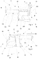
- FIG. 1 shows a connection device 1 according to a first embodiment.
- the connection device 1 comprises a connection device 10.
- the connection device 10 serves to connect a conductor 100 to a busbar 200.
- the connection device 10 comprises a spring force terminal 20, a conductor connection device 40, which is electrically conductively connected to the spring force terminal 20, and an insulating housing 60
- Insulating housing 60 comprises a housing portion 62 and a closure portion 64.
- the closure portion 64 is connected to the housing portion 62 such that the closure portion 64 is movably supported between an open position S O and a closed position S V.
- the closure portion 64 can be moved by a movement in a direction of displacement V of the open position S O in the closed position S V.
- the spring terminal 20 and the conductor terminal device 40 is received in the housing portion 62.
- the spring-loaded terminal 20 and / or the conductor connection device 40 can be held in the housing section 62 in a form-fitting manner.
- the housing section 62 has an attachment groove 66, which is suitable for receiving a section 202 of the busbar 200.
- the spring terminal 20 protrudes into the slip-on groove 66 to be brought into contact with the portion 202 and to electrically connect the spring force terminal 20 to the bus bar 200.
- the spring-loaded terminal 20 preferably protrudes at least partially out of the insulating housing 60, in particular out of the housing section 62.
- connection device 10 can be plugged onto the busbar 200 in an attachment direction A extending approximately transversely to an extension direction E of the busbar 200 in order to receive the section 202 in the attachment groove 66 when the closure section 64 assumes the open position S O. This is especially true of the FIGS. 3 and 4 seen.
- connection device 1 further comprises a conductor 100, wherein the conductor 100 is electrically conductively connected to the conductor connection device 40 of the connection device 10 by means of a permanent connection.
- the conductor 100 emerges from the insulating material housing 16, in particular from the housing section 62 in an exit direction L.
- the exit direction L runs opposite and parallel to the mounting direction A.
- the exit direction L is parallel and in the same direction as the slip A.
- the slip-on groove 66 and / or the busbar 200 is substantially rectangular in cross-section. With this configuration, the connection device 1 can be securely fastened to the busbar 200.
- the displacement direction V may be approximately orthogonal to the mounting direction A and / or approximately orthogonal to the extension direction E.
- the insulating housing 60 can have a dovetail-shaped spring 68 and a dovetail-shaped groove 70 in cross-section.
- the spring 68 can be arranged on the closure section 64 and the groove 70 can be arranged on the housing section 62.
- the spring 68 on the housing portion 62 and the groove 70 may be disposed on the closure portion 64.
- groove 70 and spring 68 extend substantially parallel to the direction of displacement V.
- the spring 68 and the groove 70 are arranged on the insulating housing 60 such that the spring 68 engages the groove 70 to hold the closure portion 64 on the housing portion 62 such that the closure portion 64 in the direction of displacement V between the open position S O and the closed position S V is movable.
- the insulating housing 60 comprises at least one lug 72, at least one first notch 74 and at least one second notch 76.
- the lug 72 is disposed on the closure portion 64 and the first and second notches 74, 76 are on the housing portion 62 arranged.
- the nose 72 may be disposed on the housing portion 62 and the notches 74, 76 on the closure portion 64.
- the nose 72, the first notch 74 and the second notch 76 are arranged on the insulating housing 60 such that the nose 72 engages in the open position S O in the first notch 74 to hold the closure portion 64 in the open position S O , and in the closed position S V in the second notch 76 engages to hold the closure portion 64 in the closed position S V.
- the opening position S O is in the FIGS. 1 . 3 . 4 and 9 played.
- the closure position S V is in the Figures 2 and 4 played.
- the spring clamp 20 and a reinforcing element 22 may include that preferably steel is made.
- the reinforcing element 22 serves on the one hand to increase the spring force of the spring-loaded terminal 20 and on the other hand to maintain the spring force over the life of the connecting device 1.
- the reinforcing element 22 is formed of a wire.
- the wire can, as in both embodiments shown to be approximately circular in cross section. Alternatively, the wire may also be approximately elliptical in cross section or rectangular in cross section.
- the spring-loaded terminal 20 may comprise a clamping portion 24 which is formed substantially U-shaped and has two clamping legs 26.
- the reinforcing element 22 may also be formed substantially U-shaped and comprise two reinforcing legs 23 which bear against an outer side 25 of the clamping legs 26.
- the clamping legs 26 may each have a free end 27.
- the clamping legs 26 may include a recess 28 adjacent to the free end 27.
- the reinforcing legs 23 may have a projection 29, which protrudes into the recess 28 or is received in the recess 28.
- the recess 28 may be formed as a trough or depression, which is in each case adapted to the contour of the projections 29 of the reinforcing legs 23.
- the clamping legs 26 are according to both embodiments on its inner side 21, in particular in the region of the recess 28 to the section 202 can be applied.
- the free ends 27 of the clamping legs 26 may project outwardly with respect to the U-shape to facilitate insertion of the section 202 in the clamping section 24.
- the permanent connection between the conductor 100 and the conductor connection device 40 by means of a material connection, in particular a solder connection 42 or a welded connection can be made.
- the permanent connection can also be done by means of a crimp connection.
- the housing portion 62 may further comprise a second wall 63, which may be formed substantially L- or U-shaped.
- the second wall 63 preferably extends along an outer side of the reinforcing element 22 and / or along the outer side 25 of the clamping section 24.
- the conductor 100 may include a first portion 102 which is electrically connected to the conductor terminal means 40 and received in the insulating housing 60, and a second portion 104 which protrudes from the insulating housing 60 and is provided with insulation 106 ,
- the closure portion 64 is connected via a hinge to the housing portion 62, wherein the hinge allows pivoting of the closure portion 64 from the open position S O in the closed position S V , and preferably the closure portion 64 and the hinge are integrally formed on the housing portion 62.
Abstract
Die Erfindung betrifft eine Anschlusseinrichtung (10) zum Anschluss eines Leiters (100) an einer Sammelschiene (200). Die Anschlusseinrichtung (10) umfasst eine Federkraftklemme (20), eine Leiteranschlusseinrichtung (40), die mit der Federkraftklemme (20) elektrisch leitend verbunden ist, und ein Isolierstoffgehäuse (60), welches einen Gehäuseabschnitt (62) aufweist. Die Federkraftklemme (20) und die Leiteranschlusseinrichtung (40) sind in dem Gehäuseabschnitt (62) aufgenommen. Der Gehäuseabschnitt (62) weist eine Aufstecknut (66) zur Aufnahme eines Teilstücks (202) der Sammelschiene (200) auf. Die Federkraftklemme (20) ragt in die Aufstecknut (66) hinein, um mit dem Teilstück (202) in Berührung gebracht zu werden und die Federkraftklemme (20) elektrisch leitend mit der Sammelschiene (200) zu verbinden. Das Isolierstoffgehäuse (60) umfasst einen Verschlussabschnitt (64), der geeignet ist, eine Öffnungsstellung (S o ) und eine Verschlussstellung (S v ) einzunehmen. Die Anschlusseinrichtung (10) ist in der Öffnungsstellung (S o ) in einer annähernd quer zu einer Erstreckungsrichtung (E) der Sammelschiene (200) verlaufenden Aufsteckrichtung (A) auf die Sammelschiene (200) aufsteckbar, um das Teilstück (202) in der Aufstecknut (66) aufzunehmen. Der Verschlussabschnitt (64) verschließt die Aufstecknut (66) in der Verschlussstellung (S v ), um das Teilstück (202) in der Verschlussstellung (S v ) formschlüssig in der Aufstecknut (66) zu halten.The invention relates to a connection device (10) for connecting a conductor (100) to a busbar (200). The connection device (10) comprises a spring-loaded terminal (20), a conductor connection device (40), which is electrically conductively connected to the spring-loaded terminal (20), and an insulating housing (60) which has a housing section (62). The spring-loaded terminal (20) and the conductor terminal device (40) are received in the housing section (62). The housing portion (62) has a Aufstecknut (66) for receiving a portion (202) of the busbar (200). The spring terminal (20) protrudes into the slip groove (66) to be brought into contact with the portion (202) and to electrically connect the spring force terminal (20) to the bus bar (200). The insulating housing (60) comprises a closure section (64) which is suitable for assuming an open position (S o) and a closed position (S v). The connection device (10) can be plugged onto the busbar (200) in the open position (S o) in a direction of attachment (A) extending approximately transversely to an extension direction (E) of the busbar (200) in order to place the section (202) in the attachment groove (66). The closure portion (64) closes the Aufstecknut (66) in the closed position (S v) to hold the portion (202) in the closed position (S v) positively in the Aufstecknut (66).
Description
Die Erfindung betrifft eine Anschlusseinrichtung zum Anschluss eines Leiters an einer Sammelschiene, insbesondere einer Sammelschiene einer Verteilereinrichtung.The invention relates to a connection device for connecting a conductor to a busbar, in particular a busbar of a distribution device.
Aus dem Stand der Technik sind Anschlusseinrichtungen der eingangs genannten Art bekannt, die geeignet sind, eine sowohl mechanische als auch eine elektrische Verbindung zwischen dem Leiter und der Sammelschiene herzustellen. Zum Anschluss des Leiters und der Sammelschiene an die Anschlusseinrichtung werden hauptsächlich Schraubklemmanschlusselemente verwendet.Connection devices of the type mentioned in the introduction are known from the prior art which are suitable for producing a mechanical as well as an electrical connection between the conductor and the busbar. To connect the conductor and the busbar to the terminal device, screw terminal connection elements are mainly used.
Aus der Druckschrift
Aus der Druckschrift
Es ist die Aufgabe der vorliegenden Erfindung eine Anschlusseinrichtung bereitzustellen, die einfach zu warten ist, eine einfache und sichere Handhabung ermöglicht und die in sicherer Weise mit der Sammelschiene verbunden werden kann.It is the object of the present invention to provide a connection device which is easy to maintain, enables easy and safe handling and which can be securely connected to the busbar.
Erfindungsgemäß wird diese Aufgabe durch eine Einrichtung nach Anspruch 1 gelöst.According to the invention, this object is achieved by a device according to
Erfindungsgemäß umfasst die Anschlusseinrichtung eine Federkraftklemme, eine Leiteranschlusseinrichtung, die mit der Federkraftklemme elektrisch leitend verbunden ist, und ein Isolierstoffgehäuse, das einen Gehäuseabschnitt aufweist. Die Federkraftklemme und die Leiteranschlusseinrichtung sind in dem Gehäuseabschnitt aufgenommen. Der Gehäuseabschnitt weist eine Aufstecknut zur Aufnahme eines Teilstücks der Sammelschiene auf. Die Federkraftklemme ragt in die Aufstecknut hinein, um mit dem Teilstück in Berührung gebracht zu werden und die Federkraftklemme elektrisch leitend mit der Sammelschiene zu verbinden. Das Isolierstoffgehäuse umfasst einen Verschlussabschnitt, der geeignet ist, eine Öffnungsstellung und eine Verschlussstellung einzunehmen. Die Anschlusseinrichtung ist in der Öffnungsstellung in einer annähernd quer zu einer Erstreckungsrichtung der Sammelschiene verlaufenden Aufsteckrichtung auf die Sammelschiene aufsteckbar, um das Teilstück in der Aufstecknut aufzunehmen. Der Verschlussabschnitt verschließt die Aufstecknut in der Verschlussstellung, um das Teilstück in der Verschlussstellung formschlüssig in der Aufstecknut zu halten.According to the invention, the connection device comprises a spring-loaded terminal, a conductor connection device which is electrically conductively connected to the spring-loaded terminal, and an insulating material housing which has a housing section. The spring-loaded terminal and the conductor connection device are accommodated in the housing section. The housing section has an attachment groove for receiving a portion of the busbar. The spring clamp protrudes into the slip-on groove to be brought into contact with the section and to electrically connect the spring-loaded terminal to the busbar. The insulating housing comprises a closure portion which is adapted to assume an open position and a closed position. The connection device can be plugged onto the busbar in the open position in a mounting direction extending approximately transversely to an extension direction of the busbar, in order to receive the section in the attachment groove. The closure portion closes the Aufstecknut in the closed position to hold the portion in the closed position positively in the Aufstecknut.
Durch die erfindungsgemäße Ausgestaltung ist die Anschlusseinrichtung in einfacher und sicherer Weise mit der Sammelschiene verbindbar. Nimmt der Verschlussabschnitt die Verschlussstellung ein, so ist die Anschlusseinrichtung formschlüssig mit dem Teilstück der Sammelschiene verbunden und ein versehentliches Abreißen der Anschlusseinrichtung von der Sammelschiene wird erschwert. Nimmt der Verschlussabschnitt die Öffnungsstellung ein, so kann die Anschlusseinrichtung durch eine Bewegung entgegen der Aufsteckrichtung in einfacher Weise von der Sammelschiene entfernt werden.As a result of the embodiment according to the invention, the connection device can be connected to the busbar in a simple and reliable manner. If the closure section adopts the closed position, then the connection device is connected in a form-fitting manner to the section of the busbar and an inadvertent tearing of the connection device from the busbar is made more difficult. If the closure section assumes the open position, then the connection device can be removed from the busbar in a simple manner by a movement counter to the attachment direction.
Vorzugsweise ist die Leiteranschlusseinrichtung geeignet, elektrisch leitend mit dem Leiter verbunden zu werden.Preferably, the conductor connection means is adapted to be electrically conductively connected to the conductor.
Vorzugsweise weist der Leiter eine Querschnittsfläche auf, die zwischen 1,5 mm2 und 35 mm2 liegt.Preferably, the conductor has a cross-sectional area which is between 1.5 mm 2 and 35 mm 2 .
In einer bevorzugten Ausgestaltung ist der Verschlussabschnitt auf dem Gehäuseabschnitt beweglich gehalten und durch eine Bewegung in einer Verschieberichtung von der Öffnungsstellung in die Verschlussstellung überführbar.In a preferred embodiment, the closure portion is movably held on the housing portion and by a movement in one Displacement direction from the open position into the closed position can be transferred.
Vorzugsweise ist der Leiter derart mit der Leiteranschlusseinrichtung verbindbar, dass der Leiter entlang einer Austrittsrichtung aus dem Isolierstoffgehäuse austritt.Preferably, the conductor can be connected to the conductor connection device in such a way that the conductor emerges from the insulating material housing along an exit direction.
Vorzugsweise verläuft die Austrittsrichtung in Wesentlichen parallel und entgegengesetzt zur Aufsteckrichtung. Das heißt, gemäß dieser Ausgestaltung ist die Anschlusseinrichtung durch eine Bewegung in Austrittrichtung auf das Teilstück aufsteckbar. Alternativ kann die Austrittsrichtung im Wesentlichen entgegengesetzt zur Aufsteckrichtung verlaufen. Gemäß dieser Ausgestaltung ist die Anschlusseinrichtung durch eine Bewegung entgegen der Austrittsrichtung auf das Teilstück aufsteckbar.Preferably, the exit direction is substantially parallel and opposite to the mounting direction. That is, according to this embodiment, the connection device can be plugged by a movement in the outlet direction of the section. Alternatively, the exit direction may be substantially opposite to the attachment direction. According to this embodiment, the connection device can be attached to the section by a movement counter to the outlet direction.
Diese Ausgestaltung bietet den Vorteil, dass der Formschluss zwischen Teilstück und Aufstecknut verbessert wird.This embodiment has the advantage that the positive connection between the section and slip-on is improved.
In einer bevorzugten Ausgestaltung verläuft die Verschieberichtung annähernd orthogonal zur Aufsteckrichtung und/oder annähernd orthogonal zur Erstreckungsrichtung.In a preferred embodiment, the displacement direction is approximately orthogonal to the mounting direction and / or approximately orthogonal to the extension direction.
Vorzugsweise weist das Isolierstoffgehäuse eine im Querschnitt schwalbenschwanzförmige Feder und eine im Querschnitt schwalbenschwanzförmige Nut auf, wobei die Feder und die Nut derart an dem Isolierstoffgehäuse angeordnet sind, dass die Feder in die Nut eingreift, um den Verschlussabschnitt an dem Gehäuseabschnitt in der Verschieberichtung zwischen der Öffnungsstellung und der Verschlussstellung beweglich zu halten.Preferably, the insulating housing has a dovetail-shaped spring in cross-section and a dovetailed groove in cross-section, wherein the spring and the groove are arranged on the insulating housing, that the spring engages in the groove to the closure portion on the housing portion in the direction of displacement between the open position and the lock position to keep moving.
Diese Ausgestaltung ermöglicht es, den Verschlussabschnitt in einfacher Weise derart an dem Gehäuseabschnitt zu halten, dass der Verschlussabschnitt zwischen der Öffnungsstellung und der Verschlussstellung beweglich gehalten ist und formschlüssig mit dem Gehäuseabschnitt verbunden ist.This configuration makes it possible to hold the closure section in a simple manner on the housing section such that the closure section is movably held between the open position and the closed position and is positively connected to the housing section.
Vorzugsweise ist die Feder an dem Verschlussabschnitt und die Nut an dem Gehäuseabschnitt angeordnet. Alternativ kann die Feder an dem Gehäuseabschnitt und die Nut an dem Verschlussabschnitt angeordnet sein.Preferably, the spring is arranged on the closure portion and the groove on the housing portion. Alternatively, the spring can be arranged on the housing section and the groove on the closure section.
In einer bevorzugten Ausgestaltung weist das Isolierstoffgehäuse wenigstens eine Nase, wenigstens eine erste Auskerbung und wenigstens eine zweite Auskerbung auf, wobei die Nase, die erste Auskerbung und die zweite Auskerbung derart an dem Isolierstoffgehäuse angeordnet sind, dass die Nase in der Öffnungsstellung in die erste Auskerbung eingreift, um den Verschlussabschnitt in der Öffnungsstellung zu halten, und in der Verschlussstellung in die zweite Auskerbung eingreift, um den Verschlussabschnitt in der Verschlussstellung zu halten.In a preferred embodiment, the insulating material housing has at least one nose, at least one first notch and at least one second notch, wherein the nose, the first notch and the second notch are arranged on the insulating housing, that the nose in the open position in the first notch engages to hold the closure portion in the open position, and engages in the closed position in the second notch to hold the closure portion in the closed position.
Vorzugsweise sind die Nase und die erste Auskerbung derart ausgebildet, dass ein Verschieben des Verschlussabschnitts entgegen der Verschieberichtung über die Öffnungsstellung hinaus verhindert wird.Preferably, the nose and the first notch are formed such that a displacement of the closure portion against the displacement direction is prevented beyond the open position addition.
Diese Ausgestaltung bietet den Vorteil, dass verhindert werden kann, dass der Verschlussabschnitt durch eine Bewegung entgegen der Verschieberichtung von dem Gehäuseabschnitt entfernt werden kann und somit verloren gehen kann.This embodiment has the advantage that it can be prevented that the closure section can be removed from the housing section by a movement counter to the direction of displacement and can thus be lost.
In einer bevorzugten Ausgestaltung ist die Nase an dem Verschlussabschnitt angeordnet und die erste Auskerbung und die zweite Auskerbung sind an dem Gehäuseabschnitt angeordnet. Alternativ kann die Nase an dem Gehäuseabschnitt angeordnet sein und die erste Auskerbung und zweite Auskerbung an dem Verschlussabschnitt angeordnet sein.In a preferred embodiment, the nose is arranged on the closure portion and the first notch and the second notch are disposed on the housing portion. Alternatively, the nose may be disposed on the housing portion and the first notch and second notch may be disposed on the closure portion.
Vorzugsweise ist der Verschlussabschnitt über ein Scharnier mit dem Gehäuseabschnitt verbunden, wobei das Scharnier ein Verschwenken des Verschlussabschnitts von der Öffnungsstellung in die Verschlussstellung ermöglicht und wobei vorzugsweise der Verschlussabschnitt und das Scharnier an dem Gehäuseabschnitt angeformt sind.Preferably, the closure portion is connected via a hinge to the housing portion, wherein the hinge allows pivoting of the closure portion from the open position to the closed position and wherein preferably the closure portion and the hinge are integrally formed on the housing portion.
Vorzugsweise umgibt das Isolierstoffgehäuse in der Verschlussstellung das Teilstück in einer quer zur Erstreckungsrichtung verlaufenden Umfangsrichtung vollumfänglich.Preferably, the insulating material housing in the closed position surrounds the portion in a circumferential direction extending transversely to the direction of extent.
Vorzugsweise umfasst die Federkraftklemme ein Verstärkungselement, das vorzugsweise aus Stahl gefertigt ist.Preferably, the spring clamp comprises a reinforcing element, which is preferably made of steel.
Diese Ausgestaltung ermöglicht es, die Klemmkraft der Federkraftklemme zu verbessern und/oder die Lebensdauer der Federkraftklemme zu erhöhen.This configuration makes it possible to improve the clamping force of the spring terminal and / or to increase the life of the spring terminal.
In einer bevorzugten Ausgestaltung ist das Verstärkungselement aus einem Draht gebildet.In a preferred embodiment, the reinforcing element is formed from a wire.
Vorzugsweise ist das Verstärkungselement aus einem umgeformten, weiterhin vorzugsweise gebogenen Draht gebildet.Preferably, the reinforcing element is formed from a formed, further preferably bent wire.
In einer bevorzugten Ausgestaltung ist der Draht in Querschnitt annähernd kreisflächenförmig oder rechteckförmig oder ellipsenflächenförmig ausgebildet.In a preferred embodiment, the wire in cross-section is approximately circular-shaped or rectangular or elliptical surface-shaped.
Vorzugsweise umfasst die Federkraftklemme einen Klemmabschnitt, der im Wesentlichen U-förmig ausgebildet ist und zwei Klemmschenkel umfasst.Preferably, the spring clamp comprises a clamping portion which is substantially U-shaped and comprises two clamping legs.
Diese Ausgestaltung ermöglicht in einfacher und sicherer Weise eine mechanische und eine elektrische Verbindung der Anschlusseinrichtung mit dem Teilstück zu erzielen.This embodiment allows a simple and secure way to achieve a mechanical and an electrical connection of the connection device with the section.
In einer bevorzugten Ausgestaltung ist das Verstärkungselement im Wesentlichen U-förmig ausgebildet und umfasst zwei Verstärkungsschenkel, die an einer Außenseite der Klemmschenkel anliegen.In a preferred embodiment, the reinforcing element is formed substantially U-shaped and comprises two reinforcing legs, which bear against an outer side of the clamping legs.
Durch diese Ausgestaltung kann die Klemmkraft der Federkraftklemme erhöht werden und die Lebensdauer der Federkraftklemme verlängert werden.By this configuration, the clamping force of the spring terminal can be increased and the life of the spring terminal can be extended.
Vorzugsweise weisen die Klemmschenkel ein freies Ende auf, wobei die Klemmschenkel benachbart zu dem freien Ende eine Ausnehmung umfassen und die Verstärkungsschenkel einen Vorsprung aufweisen, der in die Ausnehmung hineinragt.Preferably, the clamping legs have a free end, wherein the clamping legs adjacent to the free end comprise a recess and the reinforcing legs have a projection which projects into the recess.
Diese Ausgestaltung bietet den Vorteil, dass das Verstärkungselement in einfacher Weise formschlüssig und/oder kraftschlüssig mit dem Klemmeschenkel verbunden werden kann.This embodiment has the advantage that the reinforcing element can be connected in a simple manner positively and / or non-positively with the clamping leg.
Vorzugsweise ist die Ausnehmung als Vertiefung oder als Mulde ausgebildet. Alternativ kann die Ausnehmung auch als Ausschnitt ausgebildet sein, durch welchen der Vorsprung zumindest teilweise hindurchtritt.Preferably, the recess is formed as a depression or as a trough. Alternatively, the recess may also be formed as a cutout, through which the projection at least partially passes.
Die Erfindung betrifft ferner eine Anschlussvorrichtung zum Anschluss einer elektrischen Installationseinrichtung an eine Sammelschiene, wobei die Anschlussvorrichtung eine erfindungsgemäße Anschlusseinrichtung und einen Leiter umfasst, wobei der Leiter mit der Leiteranschlusseinrichtung mittels einer dauerhaften Verbindung elektrisch leitend verbunden ist.The invention further relates to a connection device for connecting an electrical installation device to a busbar, wherein the connection device comprises a connection device according to the invention and a conductor, wherein the conductor is electrically conductively connected to the conductor connection device by means of a permanent connection.
Gemäß dieser Ausgestaltung bedeutet dauerhaft, dass die Verbindung zwischen Leiter und Anschlusseinrichtung nur durch Zerstörung dieser Verbindung getrennt werden kann, das heißt, dass die dauerhafte Verbindung nicht zerstörungsfrei gelöst werden kann.According to this embodiment means permanently that the connection between the conductor and the connection device can only be separated by destruction of this connection, that is, that the permanent connection can not be solved nondestructive.
Gemäß dieser Ausgestaltung bilden die Anschlusseinrichtung und der Leiter eine Einheit. Diese Ausgestaltung bietet den Vorteil, dass sich der Leiter nicht versehentlich von der Leiteranschlusseinrichtung lösen kann und somit ein Verlieren des Leiters oder der Anschlusseinrichtung erschwert wird.According to this embodiment, the terminal device and the conductor form a unit. This embodiment has the advantage that the conductor can not accidentally come off the conductor connection device and thus a loss of the conductor or the connection device is difficult.
Vorzugsweise ist die dauerhafte Verbindung eine stoffschlüssige Verbindung, weiterhin vorzugsweise eine Lötverbindung oder eine Schweißverbindung. Alternativ oder zusätzlich ist die dauerhafte Verbindung eine Crimpverbindung.Preferably, the permanent connection is a material connection, furthermore preferably a solder connection or a welded connection. Alternatively or additionally, the permanent connection is a crimp connection.
In einer bevorzugten Ausgestaltung umfasst der Leiter einen ersten Abschnitt, der mit der Leiteranschlusseinrichtung elektrisch leitend verbunden ist und in dem Isolierstoffgehäuse aufgenommen ist, und einen zweiten Abschnitt, der aus dem Isolierstoffgehäuse herausragt und mit einer Isolierung versehen ist.In a preferred embodiment, the conductor comprises a first portion, which is electrically conductively connected to the conductor connection means and is received in the insulating housing, and a second portion which protrudes from the insulating material and is provided with an insulation.
Gemäß dieser Ausgestaltung ist ein die Anschlussvorrichtung installierender Installateur besonders gut gegenüber Stromschlägen gesichert.According to this embodiment, an installer installing the connection device is particularly well protected against electric shock.
Einzelheiten und weitere Vorteile der erfindungsgemäßen Vorrichtung und des erfindungsgemäßen Verfahrens werden anhand der nachfolgend beschriebenen Ausführungsbeispiele erläutert. Dabei veranschaulichen im Einzelnen:
-
Fig. 1 : eine perspektivische Ansicht der Anschlussvorrichtung nach einem ersten Ausführungsbeispiel; -
Fig. 2 : eine perspektivische Ansicht der Anschlussvorrichtung nach einem zweiten Ausführungsbeispiel; -
Fig. 3 : eine perspektivische Ansicht der Anschlussvorrichtung nach dem ersten Ausführungsbeispiel; -
Fig. 4 : eine perspektivische Ansicht der Anschlussvorrichtung nach dem ersten Ausführungsbeispiel; -
Fig. 5 : eine perspektivische Ansicht der Anschlussvorrichtung nach dem ersten Ausführungsbeispiel; -
Fig. 6 : eine perspektivische Ansicht der Anschlussvorrichtung nach dem ersten Ausführungsbeispiel; -
Fig. 7 : eine perspektivische Ansicht der Anschlussvorrichtung nach dem ersten Ausführungsbeispiel; -
Fig. 8 : eine perspektivische Ansicht der Anschlussvorrichtung nach dem ersten Ausführungsbeispiel, wobei zur Veranschaulichung das Isolierstoffgehäuse nicht dargestellt ist; und -
Fig. 9 : die Anschlussvorrichtung nach dem ersten Ausführungsbeispiel, wobei zur Veranschaulichung eine Wandung des Isolierstoffgehäuses nicht dargestellt ist.
-
Fig. 1 a perspective view of the connecting device according to a first embodiment; -
Fig. 2 a perspective view of the connecting device according to a second embodiment; -
Fig. 3 a perspective view of the connecting device according to the first embodiment; -
Fig. 4 a perspective view of the connecting device according to the first embodiment; -
Fig. 5 a perspective view of the connecting device according to the first embodiment; -
Fig. 6 a perspective view of the connecting device according to the first embodiment; -
Fig. 7 a perspective view of the connecting device according to the first embodiment; -
Fig. 8 a perspective view of the connecting device according to the first embodiment, wherein the insulating material housing is not shown for illustrative purposes; and -
Fig. 9 the connection device according to the first embodiment, wherein for illustrative purposes, a wall of the insulating material is not shown.
Wie insbesondere
Der Gehäuseabschnitt 62 weist eine Aufstecknut 66 auf, die zur Aufnahme eines Teilstücks 202 der Sammelschiene 200 geeignet ist. Die Federkraftklemme 20 ragt in die Aufstecknut 66 hinein, um mit dem Teilstück 202 in Berührung gebracht zu werden und die Federkraftklemme 20 elektrisch leitend mit der Sammelschiene 200 zu verbinden. Vorzugsweise ragt die Federkraftklemme 20 aus dem Isolierstoffgehäuse 60, insbesondere aus dem Gehäuseabschnitt 62 zumindest teilweise heraus.The
Die Anschlusseinrichtung 10 ist in einer annähernd Quer zur einer Erstreckungsrichtung E der Sammelschiene 200 verlaufenden Aufsteckrichtung A auf die Sammelschiene 200 aufsteckbar, um das Teilstück 202 in der Aufstecknut 66 aufzunehmen, wenn der Verschlussabschnitt 64 die Öffnungsstellung SO einnimmt. Dies ist insbesondere aus den
Die Anschlussvorrichtung 1 gemäß dem ersten Ausführungsbeispiel umfasst ferner einen Leiter 100, wobei der Leiter 100 mit der Leiteranschlusseinrichtung 40 der Anschlusseinrichtung 10 mittels einer dauerhaften Verbindung elektrisch leitend verbunden ist.The
Der Leiter 100 tritt aus dem Isolierstoffgehäuse 16, insbesondere aus dem Gehäuseabschnitt 62 in einer Austrittsrichtung L aus.The
Bei der Anschlussvorrichtung 1 gemäß dem ersten Ausführungsbeispiel verläuft die Austrittsrichtung L entgegengesetzt und parallel zur Aufsteckrichtung A.In the
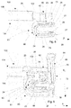
Gemäß einen zweiten Ausführungsbeispiel der Anschlussvorrichtung 1, das in
Wie insbesondre die
Vorzugsweise ist die Aufstecknut 66 und/oder die Sammelschiene 200 im Querschnitt im Wesentlichen rechteckförmig. Durch diese Ausgestaltung ist die Anschlussvorrichtung 1 sicher auf die Sammelschiene 200 befestigbar.Preferably, the slip-on
Wie insbesondere die
Wie insbesondere die
In den Ausgestaltungen gemäß beider Ausführungsbeispiele sind die Feder 68 und die Nut 70 derart an dem Isolierstoffgehäuse 60 angeordnet, dass die Feder 68 in die Nut 70 eingreift, um dem Verschlussabschnitt 64 an dem Gehäuseabschnitt 62 derart zu halten, dass der Verschlussabschnitt 64 im der Verschieberichtung V zwischen der Öffnungsstellung SO und der Verschlussstellung SV beweglich ist.In the embodiments according to both embodiments, the
Das Isolierstoffgehäuse 60 umfasst nach beiden Ausführungsbeispielen wenigsten eine Nase 72, wenigstens eine erste Auskerbung 74 und wenigstens eine zweite Auskerbung 76. Gemäß beider Ausführungsbeispiele ist die Nase 72 an dem Verschlussabschnitt 64 angeordnet und die erste und zweite Auskerbung 74, 76 sind an dem Gehäuseabschnitt 62 angeordnet. Alternativ kann auch die Nase 72 an dem Gehäuseabschnitt 62 und die Auskerbungen 74, 76 an dem Verschlussabschnitt 64 angeordnet sein.The insulating
Die Nase 72, die erste Auskerbung 74 und die zweite Auskerbung 76 sind derart an dem Isolierstoffgehäuse 60 angeordnet, dass die Nase 72 in der Öffnungsstellung SO in die erste Auskerbung 74 eingreift, um dem Verschlussabschnitt 64 in der Öffnungsstellung SO zu halten, und in der Verschlussstellung SV in die zweite Auskerbung 76 eingreift, um dem Verschlussabschnitt 64 in der Verschlussstellung SV zu halten.The
Die Öffnungsstellung SO ist in den
Wie insbesondere die
Gemäß beider Ausführungsbeispiele kann die Federkraftklemme 20 einen Klemmabschnitt 24 umfassen, der im Wesentlichen U-förmig ausgebildet ist und zwei Klemmschenkel 26 aufweist. Gemäß beider Ausführungsbeispiele kann das Verstärkungselement 22 ebenfalls im Wesentlichen U-förmig ausgebildet sein und zwei Verstärkungsschenkel 23 umfassen, die an einer Außenseite 25 der Klemmschenkel 26 anliegen.According to both embodiments, the spring-loaded
Die Klemmschenkel 26 können jeweils ein freies Ende 27 aufweisen. Die Klemmschenkel 26 können benachbart zum freien Ende 27 eine Ausnehmung 28 umfassen. Die Verstärkungsschenkel 23 können einen Vorsprung 29 aufweisen, der in die Ausnehmung 28 hineinragt oder in der Ausnehmung 28 aufgenommen ist. Gemäß beider Ausführungsbeispiele kann die Ausnehmung 28 als Mulde oder Vertiefung ausgebildet sein, die jeweils an die Kontur der Vorsprunge 29 der Verstärkungsschenkel 23 angepasst ist.The clamping
Die Klemmschenkel 26 sind gemäß beider Ausführungsbeispielen an ihrer Innenseite 21, insbesondere im Bereich der Ausnehmung 28 an das Teilstück 202 anlegbar. Die freien Enden 27 der Klemmschenkel 26 können bezüglich der U-Form nach Außen ragen, um ein Einführen des Teilstücks 202 in dem Klemmabschnitt 24 zu erleichtern.The clamping
Gemäß beider Ausführungsbeispiele kann die dauerhafte Verbindung zwischen dem Leiter 100 und der Leiteranschlusseinrichtung 40 mittels einer stoffschlüssigen Verbindung, insbesondere einer Lötverbindung 42 oder einer Schweißverbindung erfolgen. Alternativ kann die dauerhafte Verbindung auch mittels einer Crimpverbindung erfolgen.According to both embodiments, the permanent connection between the
Gemäß beider Ausführungsbeispiele kann der Gehäuseabschnitt 62 des Isolierstoffgehäuses 60 eine erste Wandung 61 umfassen, die den Boden der Aufstecknut 66 bildet. Die erste Wandung 61 kann im Wesentlichen U-förmig ausgebildet sein und verläuft vorzugsweise Abschnittsweise entlang der Innenseite 21 der Klemmschenkel 26.According to both embodiments, the
Der Gehäuseabschnitt 62 kann ferner eine zweite Wandung 63 umfassen, die im Wesentlichen L- oder U-förmig ausgebildet sein kann. Die zweite Wandung 63 verläuft dabei vorzugsweise entlang einer Außenseite des Verstärkungselements 22 und/oder entlang der Außenseite 25 des Klemmabschnitts 24. Mittels der ersten Wandung 61 und/oder der zweiten Wandung 63 kann der Klemmabschnitt 24 und/oder das Verstärkungselement 22 formschlüssig in dem Gehäuseabschnitt 62 gehalten sein.The
Gemäß beider Ausführungsbeispiele kann der Leiter 100 einen ersten Abschnitt 102, der mit der Leiteranschlusseinrichtung 40 elektrisch leitend verbunden ist und in dem Isolierstoffgehäuse 60 aufgenommen ist, und einen zweiten Abschnitt 104, der aus dem Isolierstoffgehäuse 60 herausragt und mit einer Isolierung 106 versehen ist, umfassen.According to both embodiments, the
Gemäß einer bevorzugten Ausführungsform, die in den Ausführungsbeispielen nicht wiedergegeben ist, ist der Verschlussabschnitt 64 über ein Scharnier mit dem Gehäuseabschnitt 62 verbunden, wobei das Scharnier ein Verschwenken des Verschlussabschnitts 64 von der Öffnungsstellung SO in die Verschlussstellung SV ermöglicht und wobei vorzugsweise der Verschlussabschnitt 64 und das Scharnier an dem Gehäuseabschnitt 62 angeformt sind.According to a preferred embodiment, which is not shown in the embodiments, the
Selbstverständlich ist die Erfindung nicht auf die beschriebenen und dargestellten Ausführungsformen begrenzt. Änderungen, z. B. in den Ausführungsformen der verschiedenen Bestandteile oder Ersetzungen durch technische Äquivalente sind, soweit sie im Rahmen des beanspruchten Schutzbegehrens bleiben, jederzeit möglich.Of course, the invention is not limited to the described and illustrated embodiments. Changes, eg. As in the embodiments of the various components or substitutions by technical equivalents, as far as they remain within the scope of the claimed protection, at any time possible.
Claims (15)
wobei der Gehäuseabschnitt (62) eine Aufstecknut (66) zur Aufnahme eines Teilstücks (202) der Sammelschiene (200) aufweist,
wobei die Federkraftklemme (20) in die Aufstecknut (66) hineinragt, um mit dem Teilstück (202) in Berührung gebracht zu werden und die Federkraftklemme (20) elektrisch leitend mit der Sammelschiene (200) zu verbinden,
dadurch gekennzeichnet,
dass das Isolierstoffgehäuse (60) einen Verschlussabschnitt (64) umfasst, der geeignet ist, eine Öffnungsstellung (SO) und eine Verschlussstellung (SV) einzunehmen,
wobei die Anschlusseinrichtung (10) in der Öffnungsstellung (SO) in einer annähernd quer zu einer Erstreckungsrichtung (E) der Sammelschiene (200) verlaufenden Aufsteckrichtung (A) auf die Sammelschiene (200) aufsteckbar ist, um das Teilstück (202) in der Aufstecknut (66) aufzunehmen und
wobei der Verschlussabschnitt (64) die Aufstecknut (66) in der Verschlussstellung (SV) verschließt, um das Teilstück (202) in der Verschlussstellung (SV) formschlüssig in der Aufstecknut (66) zu halten.Connecting device for connecting a conductor (100) to a busbar (200) comprising:
wherein the housing portion (62) has an attachment groove (66) for receiving a portion (202) of the busbar (200),
wherein the spring force terminal (20) protrudes into the slip-on groove (66) to be brought into contact with the portion (202) and to connect the spring-force terminal (20) in an electrically conductive manner to the busbar (200),
characterized,
in that the insulating housing (60) comprises a closure section (64) which is suitable for assuming an open position (S O ) and a closed position (S V ),
wherein the connection device (10) in the open position (S O ) in an approximately transversely to an extension direction (E) of the busbar (200) extending Aufsteckrichtung (A) on the busbar (200) can be plugged to the portion (202) in the Aufstecknut (66) record and
wherein the closure portion (64) closes the Aufstecknut (66) in the closed position (S V ) to hold the portion (202) in the closed position (S V ) positively in the Aufstecknut (66).
Applications Claiming Priority (1)
| Application Number | Priority Date | Filing Date | Title |
|---|---|---|---|
| DE102015114184.1A DE102015114184B4 (en) | 2015-08-26 | 2015-08-26 | Connecting device for connecting a conductor to a busbar |
Publications (2)
| Publication Number | Publication Date |
|---|---|
| EP3136519A1 true EP3136519A1 (en) | 2017-03-01 |
| EP3136519B1 EP3136519B1 (en) | 2019-02-13 |
Family
ID=56855395
Family Applications (1)
| Application Number | Title | Priority Date | Filing Date |
|---|---|---|---|
| EP16306077.5A Active EP3136519B1 (en) | 2015-08-26 | 2016-08-24 | Connection device for connecting a conductor to a busbar |
Country Status (2)
| Country | Link |
|---|---|
| EP (1) | EP3136519B1 (en) |
| DE (1) | DE102015114184B4 (en) |
Cited By (3)
| Publication number | Priority date | Publication date | Assignee | Title |
|---|---|---|---|---|
| CN107069335A (en) * | 2017-04-17 | 2017-08-18 | 湖南深思电工实业有限公司 | A kind of locking, distortion-free permanent seal cooling socket |
| CN110459886A (en) * | 2019-08-26 | 2019-11-15 | 福建亿瑞电力科技有限公司 | A kind of ground line fixture |
| WO2021115902A1 (en) * | 2019-12-09 | 2021-06-17 | Phoenix Contact Gmbh & Co. Kg | Connection device for a shield conductor of an electrical line |
Citations (4)
| Publication number | Priority date | Publication date | Assignee | Title |
|---|---|---|---|---|
| DE20120811U1 (en) * | 2001-12-21 | 2003-04-30 | Weidmueller Interface | Busbar terminal |
| DE102008032037A1 (en) | 2008-06-27 | 2009-12-31 | Hager Electro Gmbh & Co. Kg | Connection element for connecting flexible conductor i.e. phase conductor, to conductor rail i.e. bus bar, of electrical distributor device, has fixing unit securing element against rotation around rail longitudinal axis |
| DE102013105263B3 (en) * | 2013-05-23 | 2014-09-11 | Wago Verwaltungsgesellschaft Mbh | Connectors |
| DE102013107292A1 (en) * | 2013-07-10 | 2015-01-15 | Wago Verwaltungsgesellschaft Mbh | Connectors |
-
2015
- 2015-08-26 DE DE102015114184.1A patent/DE102015114184B4/en active Active
-
2016
- 2016-08-24 EP EP16306077.5A patent/EP3136519B1/en active Active
Patent Citations (5)
| Publication number | Priority date | Publication date | Assignee | Title |
|---|---|---|---|---|
| DE20120811U1 (en) * | 2001-12-21 | 2003-04-30 | Weidmueller Interface | Busbar terminal |
| EP1322000A2 (en) | 2001-12-21 | 2003-06-25 | Weidmüller Interface GmbH & Co. | Contact element for busbar |
| DE102008032037A1 (en) | 2008-06-27 | 2009-12-31 | Hager Electro Gmbh & Co. Kg | Connection element for connecting flexible conductor i.e. phase conductor, to conductor rail i.e. bus bar, of electrical distributor device, has fixing unit securing element against rotation around rail longitudinal axis |
| DE102013105263B3 (en) * | 2013-05-23 | 2014-09-11 | Wago Verwaltungsgesellschaft Mbh | Connectors |
| DE102013107292A1 (en) * | 2013-07-10 | 2015-01-15 | Wago Verwaltungsgesellschaft Mbh | Connectors |
Cited By (4)
| Publication number | Priority date | Publication date | Assignee | Title |
|---|---|---|---|---|
| CN107069335A (en) * | 2017-04-17 | 2017-08-18 | 湖南深思电工实业有限公司 | A kind of locking, distortion-free permanent seal cooling socket |
| CN107069335B (en) * | 2017-04-17 | 2023-07-14 | 湖南深思电工实业有限公司 | Anti-loosening and anti-deformation durable socket |
| CN110459886A (en) * | 2019-08-26 | 2019-11-15 | 福建亿瑞电力科技有限公司 | A kind of ground line fixture |
| WO2021115902A1 (en) * | 2019-12-09 | 2021-06-17 | Phoenix Contact Gmbh & Co. Kg | Connection device for a shield conductor of an electrical line |
Also Published As
| Publication number | Publication date |
|---|---|
| DE102015114184A1 (en) | 2017-03-02 |
| DE102015114184B4 (en) | 2019-01-24 |
| EP3136519B1 (en) | 2019-02-13 |
Similar Documents
| Publication | Publication Date | Title |
|---|---|---|
| EP2956993B1 (en) | Spring clamp contact and connecting terminal for electrical conductors | |
| DE102010014144C5 (en) | Electrical connection terminal | |
| DE102010014143B4 (en) | Actuation device for an electrical connection terminal | |
| EP3111513A1 (en) | Connection terminal and spring-loaded terminal contact therefor | |
| DE102006014646A1 (en) | Terminal for printed circuit boards | |
| EP3292591B1 (en) | Conductor connection clamp | |
| EP0800233A1 (en) | Contact spring, specially adapted for an electrical connector | |
| WO2018041774A2 (en) | Conductor terminal | |
| DE19810310C5 (en) | Terminal for electrical conductors | |
| DE19940971B4 (en) | Electrical conductor terminal with a busbar | |
| DE202019105009U1 (en) | Conductor connection terminal | |
| DE202016100798U1 (en) | Spring terminal | |
| EP3136519B1 (en) | Connection device for connecting a conductor to a busbar | |
| EP0735616A2 (en) | Electric connector, especially for circuit boards | |
| DE8125854U1 (en) | Installation part designed as an electrical plug or as a socket or as a coupling socket | |
| DE102015114182A1 (en) | Connecting device for connecting a conductor to a busbar | |
| DE102012006500A1 (en) | Pole terminal for a socket insert | |
| DE102009017541A1 (en) | Spring plug terminal | |
| DE102015104629B4 (en) | Clamping spring for a conductor connection terminal and conductor connection terminal with corresponding clamping spring | |
| EP1916741A1 (en) | Installation switching device and terminal clamp therefor | |
| DE102017126185A1 (en) | Contact element with a clamping connection for stranded conductors | |
| DE2724354A1 (en) | Screwless terminal for connecting two wires - incorporates leaf spring pressing both wire ends against conducting insert | |
| DE19817062C2 (en) | Clamping device for an electrical line | |
| DE2528487A1 (en) | Electrical connector joint for conductors - has terminal members passing into connector block with leaf spring retaining clips matching with wnd tages on cable | |
| EP3273543B1 (en) | Connection device for connecting a conductor to a busbar |
Legal Events
| Date | Code | Title | Description |
|---|---|---|---|
| PUAI | Public reference made under article 153(3) epc to a published international application that has entered the european phase |
Free format text: ORIGINAL CODE: 0009012 |
|
| STAA | Information on the status of an ep patent application or granted ep patent |
Free format text: STATUS: THE APPLICATION HAS BEEN PUBLISHED |
|
| AK | Designated contracting states |
Kind code of ref document: A1 Designated state(s): AL AT BE BG CH CY CZ DE DK EE ES FI FR GB GR HR HU IE IS IT LI LT LU LV MC MK MT NL NO PL PT RO RS SE SI SK SM TR |
|
| AX | Request for extension of the european patent |
Extension state: BA ME |
|
| STAA | Information on the status of an ep patent application or granted ep patent |
Free format text: STATUS: REQUEST FOR EXAMINATION WAS MADE |
|
| 17P | Request for examination filed |
Effective date: 20170901 |
|
| RBV | Designated contracting states (corrected) |
Designated state(s): AL AT BE BG CH CY CZ DE DK EE ES FI FR GB GR HR HU IE IS IT LI LT LU LV MC MK MT NL NO PL PT RO RS SE SI SK SM TR |
|
| STAA | Information on the status of an ep patent application or granted ep patent |
Free format text: STATUS: EXAMINATION IS IN PROGRESS |
|
| 17Q | First examination report despatched |
Effective date: 20171219 |
|
| GRAP | Despatch of communication of intention to grant a patent |
Free format text: ORIGINAL CODE: EPIDOSNIGR1 |
|
| STAA | Information on the status of an ep patent application or granted ep patent |
Free format text: STATUS: GRANT OF PATENT IS INTENDED |
|
| RIC1 | Information provided on ipc code assigned before grant |
Ipc: H01R 13/11 20060101ALN20180803BHEP Ipc: H01R 13/639 20060101ALI20180803BHEP Ipc: H01R 13/18 20060101ALN20180803BHEP Ipc: H01R 25/14 20060101AFI20180803BHEP |
|
| INTG | Intention to grant announced |
Effective date: 20180822 |
|
| GRAS | Grant fee paid |
Free format text: ORIGINAL CODE: EPIDOSNIGR3 |
|
| GRAA | (expected) grant |
Free format text: ORIGINAL CODE: 0009210 |
|
| STAA | Information on the status of an ep patent application or granted ep patent |
Free format text: STATUS: THE PATENT HAS BEEN GRANTED |
|
| AK | Designated contracting states |
Kind code of ref document: B1 Designated state(s): AL AT BE BG CH CY CZ DE DK EE ES FI FR GB GR HR HU IE IS IT LI LT LU LV MC MK MT NL NO PL PT RO RS SE SI SK SM TR |
|
| REG | Reference to a national code |
Ref country code: GB Ref legal event code: FG4D Free format text: NOT ENGLISH |
|
| REG | Reference to a national code |
Ref country code: CH Ref legal event code: EP Ref country code: AT Ref legal event code: REF Ref document number: 1096740 Country of ref document: AT Kind code of ref document: T Effective date: 20190215 |
|
| REG | Reference to a national code |
Ref country code: IE Ref legal event code: FG4D Free format text: LANGUAGE OF EP DOCUMENT: GERMAN |
|
| REG | Reference to a national code |
Ref country code: DE Ref legal event code: R096 Ref document number: 502016003395 Country of ref document: DE |
|
| REG | Reference to a national code |
Ref country code: LT Ref legal event code: MG4D |
|
| REG | Reference to a national code |
Ref country code: NL Ref legal event code: MP Effective date: 20190213 |
|
| PG25 | Lapsed in a contracting state [announced via postgrant information from national office to epo] |
Ref country code: LT Free format text: LAPSE BECAUSE OF FAILURE TO SUBMIT A TRANSLATION OF THE DESCRIPTION OR TO PAY THE FEE WITHIN THE PRESCRIBED TIME-LIMIT Effective date: 20190213 Ref country code: SE Free format text: LAPSE BECAUSE OF FAILURE TO SUBMIT A TRANSLATION OF THE DESCRIPTION OR TO PAY THE FEE WITHIN THE PRESCRIBED TIME-LIMIT Effective date: 20190213 Ref country code: NL Free format text: LAPSE BECAUSE OF FAILURE TO SUBMIT A TRANSLATION OF THE DESCRIPTION OR TO PAY THE FEE WITHIN THE PRESCRIBED TIME-LIMIT Effective date: 20190213 Ref country code: NO Free format text: LAPSE BECAUSE OF FAILURE TO SUBMIT A TRANSLATION OF THE DESCRIPTION OR TO PAY THE FEE WITHIN THE PRESCRIBED TIME-LIMIT Effective date: 20190513 Ref country code: PT Free format text: LAPSE BECAUSE OF FAILURE TO SUBMIT A TRANSLATION OF THE DESCRIPTION OR TO PAY THE FEE WITHIN THE PRESCRIBED TIME-LIMIT Effective date: 20190613 Ref country code: FI Free format text: LAPSE BECAUSE OF FAILURE TO SUBMIT A TRANSLATION OF THE DESCRIPTION OR TO PAY THE FEE WITHIN THE PRESCRIBED TIME-LIMIT Effective date: 20190213 |
|
| PG25 | Lapsed in a contracting state [announced via postgrant information from national office to epo] |
Ref country code: BG Free format text: LAPSE BECAUSE OF FAILURE TO SUBMIT A TRANSLATION OF THE DESCRIPTION OR TO PAY THE FEE WITHIN THE PRESCRIBED TIME-LIMIT Effective date: 20190513 Ref country code: RS Free format text: LAPSE BECAUSE OF FAILURE TO SUBMIT A TRANSLATION OF THE DESCRIPTION OR TO PAY THE FEE WITHIN THE PRESCRIBED TIME-LIMIT Effective date: 20190213 Ref country code: IS Free format text: LAPSE BECAUSE OF FAILURE TO SUBMIT A TRANSLATION OF THE DESCRIPTION OR TO PAY THE FEE WITHIN THE PRESCRIBED TIME-LIMIT Effective date: 20190613 Ref country code: LV Free format text: LAPSE BECAUSE OF FAILURE TO SUBMIT A TRANSLATION OF THE DESCRIPTION OR TO PAY THE FEE WITHIN THE PRESCRIBED TIME-LIMIT Effective date: 20190213 Ref country code: HR Free format text: LAPSE BECAUSE OF FAILURE TO SUBMIT A TRANSLATION OF THE DESCRIPTION OR TO PAY THE FEE WITHIN THE PRESCRIBED TIME-LIMIT Effective date: 20190213 Ref country code: GR Free format text: LAPSE BECAUSE OF FAILURE TO SUBMIT A TRANSLATION OF THE DESCRIPTION OR TO PAY THE FEE WITHIN THE PRESCRIBED TIME-LIMIT Effective date: 20190514 |
|
| PG25 | Lapsed in a contracting state [announced via postgrant information from national office to epo] |
Ref country code: ES Free format text: LAPSE BECAUSE OF FAILURE TO SUBMIT A TRANSLATION OF THE DESCRIPTION OR TO PAY THE FEE WITHIN THE PRESCRIBED TIME-LIMIT Effective date: 20190213 Ref country code: DK Free format text: LAPSE BECAUSE OF FAILURE TO SUBMIT A TRANSLATION OF THE DESCRIPTION OR TO PAY THE FEE WITHIN THE PRESCRIBED TIME-LIMIT Effective date: 20190213 Ref country code: AL Free format text: LAPSE BECAUSE OF FAILURE TO SUBMIT A TRANSLATION OF THE DESCRIPTION OR TO PAY THE FEE WITHIN THE PRESCRIBED TIME-LIMIT Effective date: 20190213 Ref country code: SK Free format text: LAPSE BECAUSE OF FAILURE TO SUBMIT A TRANSLATION OF THE DESCRIPTION OR TO PAY THE FEE WITHIN THE PRESCRIBED TIME-LIMIT Effective date: 20190213 Ref country code: IT Free format text: LAPSE BECAUSE OF FAILURE TO SUBMIT A TRANSLATION OF THE DESCRIPTION OR TO PAY THE FEE WITHIN THE PRESCRIBED TIME-LIMIT Effective date: 20190213 Ref country code: EE Free format text: LAPSE BECAUSE OF FAILURE TO SUBMIT A TRANSLATION OF THE DESCRIPTION OR TO PAY THE FEE WITHIN THE PRESCRIBED TIME-LIMIT Effective date: 20190213 Ref country code: RO Free format text: LAPSE BECAUSE OF FAILURE TO SUBMIT A TRANSLATION OF THE DESCRIPTION OR TO PAY THE FEE WITHIN THE PRESCRIBED TIME-LIMIT Effective date: 20190213 Ref country code: CZ Free format text: LAPSE BECAUSE OF FAILURE TO SUBMIT A TRANSLATION OF THE DESCRIPTION OR TO PAY THE FEE WITHIN THE PRESCRIBED TIME-LIMIT Effective date: 20190213 |
|
| REG | Reference to a national code |
Ref country code: DE Ref legal event code: R097 Ref document number: 502016003395 Country of ref document: DE |
|
| PG25 | Lapsed in a contracting state [announced via postgrant information from national office to epo] |
Ref country code: PL Free format text: LAPSE BECAUSE OF FAILURE TO SUBMIT A TRANSLATION OF THE DESCRIPTION OR TO PAY THE FEE WITHIN THE PRESCRIBED TIME-LIMIT Effective date: 20190213 Ref country code: SM Free format text: LAPSE BECAUSE OF FAILURE TO SUBMIT A TRANSLATION OF THE DESCRIPTION OR TO PAY THE FEE WITHIN THE PRESCRIBED TIME-LIMIT Effective date: 20190213 |
|
| PLBE | No opposition filed within time limit |
Free format text: ORIGINAL CODE: 0009261 |
|
| STAA | Information on the status of an ep patent application or granted ep patent |
Free format text: STATUS: NO OPPOSITION FILED WITHIN TIME LIMIT |
|
| 26N | No opposition filed |
Effective date: 20191114 |
|
| PG25 | Lapsed in a contracting state [announced via postgrant information from national office to epo] |
Ref country code: SI Free format text: LAPSE BECAUSE OF FAILURE TO SUBMIT A TRANSLATION OF THE DESCRIPTION OR TO PAY THE FEE WITHIN THE PRESCRIBED TIME-LIMIT Effective date: 20190213 |
|
| PG25 | Lapsed in a contracting state [announced via postgrant information from national office to epo] |
Ref country code: TR Free format text: LAPSE BECAUSE OF FAILURE TO SUBMIT A TRANSLATION OF THE DESCRIPTION OR TO PAY THE FEE WITHIN THE PRESCRIBED TIME-LIMIT Effective date: 20190213 |
|
| PG25 | Lapsed in a contracting state [announced via postgrant information from national office to epo] |
Ref country code: MC Free format text: LAPSE BECAUSE OF FAILURE TO SUBMIT A TRANSLATION OF THE DESCRIPTION OR TO PAY THE FEE WITHIN THE PRESCRIBED TIME-LIMIT Effective date: 20190213 Ref country code: LU Free format text: LAPSE BECAUSE OF NON-PAYMENT OF DUE FEES Effective date: 20190824 Ref country code: CH Free format text: LAPSE BECAUSE OF NON-PAYMENT OF DUE FEES Effective date: 20190831 Ref country code: LI Free format text: LAPSE BECAUSE OF NON-PAYMENT OF DUE FEES Effective date: 20190831 |
|
| REG | Reference to a national code |
Ref country code: BE Ref legal event code: MM Effective date: 20190831 |
|
| PG25 | Lapsed in a contracting state [announced via postgrant information from national office to epo] |
Ref country code: FR Free format text: LAPSE BECAUSE OF NON-PAYMENT OF DUE FEES Effective date: 20190831 Ref country code: IE Free format text: LAPSE BECAUSE OF NON-PAYMENT OF DUE FEES Effective date: 20190824 |
|
| PG25 | Lapsed in a contracting state [announced via postgrant information from national office to epo] |
Ref country code: BE Free format text: LAPSE BECAUSE OF NON-PAYMENT OF DUE FEES Effective date: 20190831 |
|
| GBPC | Gb: european patent ceased through non-payment of renewal fee |
Effective date: 20200824 |
|
| PG25 | Lapsed in a contracting state [announced via postgrant information from national office to epo] |
Ref country code: CY Free format text: LAPSE BECAUSE OF FAILURE TO SUBMIT A TRANSLATION OF THE DESCRIPTION OR TO PAY THE FEE WITHIN THE PRESCRIBED TIME-LIMIT Effective date: 20190213 |
|
| PG25 | Lapsed in a contracting state [announced via postgrant information from national office to epo] |
Ref country code: MT Free format text: LAPSE BECAUSE OF FAILURE TO SUBMIT A TRANSLATION OF THE DESCRIPTION OR TO PAY THE FEE WITHIN THE PRESCRIBED TIME-LIMIT Effective date: 20190213 Ref country code: HU Free format text: LAPSE BECAUSE OF FAILURE TO SUBMIT A TRANSLATION OF THE DESCRIPTION OR TO PAY THE FEE WITHIN THE PRESCRIBED TIME-LIMIT; INVALID AB INITIO Effective date: 20160824 |
|
| PG25 | Lapsed in a contracting state [announced via postgrant information from national office to epo] |
Ref country code: GB Free format text: LAPSE BECAUSE OF NON-PAYMENT OF DUE FEES Effective date: 20200824 |
|
| PG25 | Lapsed in a contracting state [announced via postgrant information from national office to epo] |
Ref country code: MK Free format text: LAPSE BECAUSE OF FAILURE TO SUBMIT A TRANSLATION OF THE DESCRIPTION OR TO PAY THE FEE WITHIN THE PRESCRIBED TIME-LIMIT Effective date: 20190213 |
|
| REG | Reference to a national code |
Ref country code: AT Ref legal event code: MM01 Ref document number: 1096740 Country of ref document: AT Kind code of ref document: T Effective date: 20210824 |
|
| PG25 | Lapsed in a contracting state [announced via postgrant information from national office to epo] |
Ref country code: AT Free format text: LAPSE BECAUSE OF NON-PAYMENT OF DUE FEES Effective date: 20210824 |
|
| P01 | Opt-out of the competence of the unified patent court (upc) registered |
Effective date: 20230606 |
|
| PGFP | Annual fee paid to national office [announced via postgrant information from national office to epo] |
Ref country code: DE Payment date: 20230829 Year of fee payment: 8 |