EP3136459B1 - Flexible organische lichtemittierende anzeigevorrichtung - Google Patents
Flexible organische lichtemittierende anzeigevorrichtung Download PDFInfo
- Publication number
- EP3136459B1 EP3136459B1 EP16186330.3A EP16186330A EP3136459B1 EP 3136459 B1 EP3136459 B1 EP 3136459B1 EP 16186330 A EP16186330 A EP 16186330A EP 3136459 B1 EP3136459 B1 EP 3136459B1
- Authority
- EP
- European Patent Office
- Prior art keywords
- flexible substrate
- organic light
- flexible
- display device
- adhesive layer
- Prior art date
- Legal status (The legal status is an assumption and is not a legal conclusion. Google has not performed a legal analysis and makes no representation as to the accuracy of the status listed.)
- Active
Links
Images

Classifications
-
- H—ELECTRICITY
- H10—SEMICONDUCTOR DEVICES; ELECTRIC SOLID-STATE DEVICES NOT OTHERWISE PROVIDED FOR
- H10K—ORGANIC ELECTRIC SOLID-STATE DEVICES
- H10K77/00—Constructional details of devices covered by this subclass and not covered by groups H10K10/80, H10K30/80, H10K50/80 or H10K59/80
- H10K77/10—Substrates, e.g. flexible substrates
- H10K77/111—Flexible substrates
-
- H—ELECTRICITY
- H10—SEMICONDUCTOR DEVICES; ELECTRIC SOLID-STATE DEVICES NOT OTHERWISE PROVIDED FOR
- H10K—ORGANIC ELECTRIC SOLID-STATE DEVICES
- H10K50/00—Organic light-emitting devices
- H10K50/80—Constructional details
- H10K50/84—Passivation; Containers; Encapsulations
- H10K50/842—Containers
- H10K50/8426—Peripheral sealing arrangements, e.g. adhesives, sealants
-
- H—ELECTRICITY
- H10—SEMICONDUCTOR DEVICES; ELECTRIC SOLID-STATE DEVICES NOT OTHERWISE PROVIDED FOR
- H10K—ORGANIC ELECTRIC SOLID-STATE DEVICES
- H10K50/00—Organic light-emitting devices
- H10K50/80—Constructional details
- H10K50/84—Passivation; Containers; Encapsulations
- H10K50/844—Encapsulations
-
- H—ELECTRICITY
- H10—SEMICONDUCTOR DEVICES; ELECTRIC SOLID-STATE DEVICES NOT OTHERWISE PROVIDED FOR
- H10K—ORGANIC ELECTRIC SOLID-STATE DEVICES
- H10K50/00—Organic light-emitting devices
- H10K50/80—Constructional details
- H10K50/84—Passivation; Containers; Encapsulations
- H10K50/846—Passivation; Containers; Encapsulations comprising getter material or desiccants
-
- H—ELECTRICITY
- H10—SEMICONDUCTOR DEVICES; ELECTRIC SOLID-STATE DEVICES NOT OTHERWISE PROVIDED FOR
- H10K—ORGANIC ELECTRIC SOLID-STATE DEVICES
- H10K59/00—Integrated devices, or assemblies of multiple devices, comprising at least one organic light-emitting element covered by group H10K50/00
- H10K59/80—Constructional details
- H10K59/87—Passivation; Containers; Encapsulations
- H10K59/873—Encapsulations
-
- H—ELECTRICITY
- H10—SEMICONDUCTOR DEVICES; ELECTRIC SOLID-STATE DEVICES NOT OTHERWISE PROVIDED FOR
- H10K—ORGANIC ELECTRIC SOLID-STATE DEVICES
- H10K2102/00—Constructional details relating to the organic devices covered by this subclass
- H10K2102/301—Details of OLEDs
- H10K2102/311—Flexible OLED
-
- H—ELECTRICITY
- H10—SEMICONDUCTOR DEVICES; ELECTRIC SOLID-STATE DEVICES NOT OTHERWISE PROVIDED FOR
- H10K—ORGANIC ELECTRIC SOLID-STATE DEVICES
- H10K2102/00—Constructional details relating to the organic devices covered by this subclass
- H10K2102/301—Details of OLEDs
- H10K2102/351—Thickness
-
- Y—GENERAL TAGGING OF NEW TECHNOLOGICAL DEVELOPMENTS; GENERAL TAGGING OF CROSS-SECTIONAL TECHNOLOGIES SPANNING OVER SEVERAL SECTIONS OF THE IPC; TECHNICAL SUBJECTS COVERED BY FORMER USPC CROSS-REFERENCE ART COLLECTIONS [XRACs] AND DIGESTS
- Y02—TECHNOLOGIES OR APPLICATIONS FOR MITIGATION OR ADAPTATION AGAINST CLIMATE CHANGE
- Y02E—REDUCTION OF GREENHOUSE GAS [GHG] EMISSIONS, RELATED TO ENERGY GENERATION, TRANSMISSION OR DISTRIBUTION
- Y02E10/00—Energy generation through renewable energy sources
- Y02E10/50—Photovoltaic [PV] energy
- Y02E10/549—Organic PV cells
-
- Y—GENERAL TAGGING OF NEW TECHNOLOGICAL DEVELOPMENTS; GENERAL TAGGING OF CROSS-SECTIONAL TECHNOLOGIES SPANNING OVER SEVERAL SECTIONS OF THE IPC; TECHNICAL SUBJECTS COVERED BY FORMER USPC CROSS-REFERENCE ART COLLECTIONS [XRACs] AND DIGESTS
- Y02—TECHNOLOGIES OR APPLICATIONS FOR MITIGATION OR ADAPTATION AGAINST CLIMATE CHANGE
- Y02P—CLIMATE CHANGE MITIGATION TECHNOLOGIES IN THE PRODUCTION OR PROCESSING OF GOODS
- Y02P70/00—Climate change mitigation technologies in the production process for final industrial or consumer products
- Y02P70/50—Manufacturing or production processes characterised by the final manufactured product
Definitions
- the present disclosure relates to a flexible organic light-emitting display device having a structure showing minimal deformation against bending stress.
- Such display devices include a liquid crystal display (LCD) device, a plasma display panel (PDP) device, a field emission display (FED) device, an electro-wetting display (EWD) device, quantum dot displays, and an organic light-emitting display (OLED) device, etc.
- LCD liquid crystal display
- PDP plasma display panel
- FED field emission display
- EWD electro-wetting display
- OLED organic light-emitting display
- an organic light-emitting display (OLED) device is cable of producing light and thus does not require an additional light source, as in a liquid crystal display (LCD) device. Therefore, an organic light-emitting display device can be made lighter and thinner than an LCD device. Further, an organic light-emitting display device has advantages in that it is driven with low voltage to consume less power, and in that it has shorter response time, wider viewing angle and higher contrast ratio (CR). For these reasons, an organic light-emitting display device is currently under development as the next generation display device. Despite such advantages, organic light-emitting display devices are less reliable than other display devices since organic light-emitting materials are especially vulnerable to moisture and oxygen.
- An organic light-emitting display device includes an organic light-emitting element including an anode, an organic emission layer and a cathode.
- the organic emission layer emits light by combining holes from the anode and electrons from the cathode.
- the organic emission layer is very vulnerable to moisture and oxygen and thus an encapsulation structure is required.
- a flexible organic light-emitting display device has been regarded as the next generation display device.
- Such flexible organic light-emitting display device is fabricated by forming a display area and various conductive lines on a flexible substrate made of plastic or the like so that it can display images even if it is bent like paper.
- WO 2014/136259 A1 describes a light emitting element which includes a glass substrate, a second electrode, an organic functional layer, a first electrode, a sealing layer, a resin layer, and a light extraction film.
- a Young's modulus of the glass substrate 110 is 70 GPa
- a Young's modulus of the resin layer is 6 GPa
- a Young's modulus of the light extraction film is 3 Gpa.
- US 2015/048349 A1 describes a display device.
- the display device includes a display area and a light-emitting element including an EL layer.
- a first substrate and a second substrate are attached to each other with a bonding layer provided therebetween.
- One surface of the first substrate is provided with a third substrate with a bonding layer provided therebetween.
- One surface of the second substrate is provided with a fourth substrate with a bonding layer provided therebetween.
- the inventor of the present disclosure has studied on flexible organic light-emitting display device capable of being rolled up (e.g. into a scroll-like form) and stored or retracted in such manner.
- Such flexible organic light-emitting display devices may be kept in the form of a scroll for a long-term period (e.g., more than 100 hours) due to non-use, portability, or other reasons.
- a flexible organic light-emitting display device is unrolled after being rolled up for such a long-term period, it may be deformed or other irregularities may occur.
- the inventor of the present disclosure has analyzed the relationship among various elements of the flexible organic light-emitting display device to find factors that contribute to such deformation.
- An object of the present disclosure is to provide a flexible organic light-emitting display device capable of reducing the degree of deformation occurring when it is stored in a rolled-up form (e.g. like a scroll) for a long-term period.
- Another object of the present disclosure is to provide a flexible organic light-emitting display device in which thickness of each substrate is optimized so that the flexible organic light-emitting display device can be rolled up (e.g. into a scroll) with minimal deformation.
- the other object of the present disclosure is to provide a flexible organic light-emitting display device that has a resilience ability so that it is not deformed after being rolled up for a long-term period and has strength against impact (i.e., is not easily broken) by way of adjusting the Young's modulus of an encapsulation unit of the flexible organic light-emitting display device.
- the other object of the present disclosure is to provide a flexible organic light-emitting display device with improved reliability and durability of an encapsulation unit thereof.
- an organic light-emitting display device includes: a first flexible substrate; a second flexible substrate facing the first flexible substrate; a plurality of organic light-emitting pixels on the first flexible substrate and interposed between the first flexible substrate and the second flexible substrate; an encapsulation unit between the first flexible substrate and the second flexible substrate to protect the plurality of organic light-emitting pixels from oxygen and moisture; and an adhesive layer on the encapsulation unit to adhere the first flexible substrate and the second flexible substrate and as further defined in claim 1.
- the plurality of organic light-emitting pixels is configured to be adjacent to a neutral plane.
- the adhesive layer has a Young's modulus that is equal to or larger than a certain value so that the first flexible substrate is not deformed by bending stress if it is retracted in a rolled up form for a certain period of time.
- the thickness of the adhesive layer is determined with respect to the thickness of the first flexible substrate, the curvature radius threshold of the first flexible substrate and the Young's modulus value of the adhesive layer.
- the first flexible substrate is configured to receive compressive stress and the second flexible substrate is configured to receive tensile stress, such that compressive stress is exerted on the first flexible substrate and tensile stress is exerted on the second flexible substrate when the first substrate is rolled up.
- the second flexible substrate is made of a metal plate having a higher breaking strength against tensile stress than that of the first flexible substrate, wherein the first flexible substrate includes a glass substrate.
- the second flexible substrate has a thickness between 10 ⁇ m and 120 ⁇ m.
- the first flexible substrate is made of a material having a higher breaking strength against compressive stress than that of the second flexible substrate.
- the first flexible substrate is an etched glass substrate having a thickness between 30 ⁇ m and 100 ⁇ m.
- the thickness of the adhesive layer is between 40 ⁇ m and 60 ⁇ m.
- the adhesive layer further comprises a first adhesive layer adjacent to the plurality of organic light-emitting pixels, and a second adhesive layer adjacent to the second flexible substrate and containing a moisture absorbent.
- a thickness of the first adhesive layer is at least 5 ⁇ m
- a thickness of the second adhesive layer is equal to the thickness of the adhesive layer minus the thickness of the first adhesive layer.
- the adhesive layer is made of an epoxy resin having the Young's modulus of 900 MPa or higher under cured status.
- the first flexible substrate is capable of being rolled up to have a curvature radius equal to or larger than a minimum curvature radius that maintains an elastic deformation property.
- the second flexible substrate is capable of being rolled up to have a curvature radius equal to or larger than a minimum curvature radius that maintains an elastic deformation property.
- the adhesive layer has an elastic deformation property
- the Young's modulus of the first flexible substrate and the second flexible substrate is larger than that of the adhesive layer.
- the first flexible substrate has a brittle property while having the elastic deformation property.
- the first flexible substrate is capable of being rolled up such that the first flexible substrate receives a stress below a value that causes the brittle property.
- the second flexible substrate has a plastic deformation property while having the elastic deformation property.
- the second flexible substrate is capable of being rolled up such that the second flexible substrate receives a stress below a value that causes the plastic deformation property.
- the plurality of organic light-emitting pixels may be adjacent to a neutral plane.
- the adhesive layer is made of an elastomer and has the Young's modulus between 5 MPa and 100 MPa.
- a surface of the first flexible substrate is etched, and the etched surface is configured to receive tensile stress.
- the degree of deformation of a flexible organic light-emitting display device when it is rolled into a scroll and kept in the form of the scroll can be reduced.
- the thickness of an encapsulation unit of a flexible organic light-emitting display device is reduced, thereby reducing the curvature radius threshold value that determines the limit of the diameter of the flexible organic light-emitting display device, in which can be rolled into.
- an element A on an element B refers to that the element A may be disposed directly on the element B and/or the element A may be disposed indirectly on the element B via another element C.
- the room temperature may refer to approximately 15°C to 35°C, specifically approximately 20°C to 25°C, and more specifically 25°C.
- the adhesive force refers to that measured on glass (or the particular material to which the adhesive acts on) unless stated otherwise.
- first, second and the like in the descriptions and in the claims are used for distinguishing between similar elements and not necessarily for describing a sequential or chronological order. These terms are used to merely distinguish one element from another. Accordingly, as used herein, a first element may be a second element within the technical idea of the present disclosure.
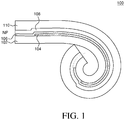
- FIG. 1 is a schematic cross-sectional view of a flexible organic light-emitting display device according to an exemplary embodiment of the present disclosure.
- the organic light-emitting display device 100 includes a first flexible substrate 102, a plurality of organic light-emitting pixels 104, an encapsulation unit 106, an adhesive layer 108 and a second flexible substrate 110.
- the first flexible substrate 102 has flexible characteristics.
- a plurality of organic light-emitting pixels 104 is disposed on the first flexible substrate 102. Images are displayed by the plurality of organic light-emitting pixels 104.
- the encapsulation unit 106 is disposed on the plurality of organic light-emitting pixels 104 to protect the plurality of organic light-emitting pixels 104 from oxygen and moisture.
- the adhesive layer 108 attaches the encapsulation unit 106 of the first flexible substrate 102 to the second flexible substrate 110.
- the flexible organic light-emitting display device 100 can be rolled into a scroll or otherwise configured into a more compact form.
- the first flexible substrate 102 and the second flexible substrate 110 of the flexible organic light-emitting display device 100 can be made of different materials.
- the flexible organic light-emitting display device 100 can be rolled up such that the ends of the first and second flexible substrates 102, 110 are curved toward the first flexible substrate 102.
- the first flexible substrate 102 receives compressive stress when the organic light-emitting display device 100 is rolled up.
- the plurality of organic light-emitting pixels 104 is located on a neutral plane (NP).
- the encapsulation unit 106 has a certain minimum Young's modulus value so that it is not deformed by bending stress when it is kept in the form of a scroll or in some other compact form.
- the second flexible substrate 110 receives tensile stress when it is rolled up.
- the second flexible substrate 110 is made of a material having a higher breaking strength versus tensile stress than that of the first flexible substrate 102.
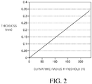
- FIG. 2 is a graph for illustrating thickness versus curvature radius threshold of the first flexible substrate 102 of the flexible organic light-emitting display device 100 according to an exemplary embodiment of the present disclosure.
- Equation 1 shown below expresses thickness versus curvature radius threshold of the first flexible substrate of the flexible organic light-emitting display device according to the exemplary embodiment of the present disclosure.
- the first flexible substrate 102 has flexible characteristics.
- the first flexible substrate 102 is made of glass.
- a glass substrate has excellent water vapor transmission rate (WVTR), is flexible and has transparency at the visible wavelengths (i.e. has see-through (e.g., transparent) characteristics).
- WVTR water vapor transmission rate
- the thickness of the glass as the first flexible substrate 102 has to be thin.
- various factors have to be considered in determining the thickness of the glass substrate, to enable it to be rolled into a scroll with sufficient strength.
- the radius of a circular shape when the flexible organic light-emitting display device 100 is rolled up into a scroll or cylinder as small as possible may be determined as 100 mm. Then, the curvature radius (i.e., the curvature radius 1 R is equivalent to 1 mm) of the first flexible substrate 102 is 100R.
- the radius of the circle i.e., the radius of circular shape
- the curvature radius of the first flexible substrate 102 is 50R.
- the thickness of the first flexible substrate 102 may be determined based on a first bending stress threshold ⁇ TH and a Young's modulus E.
- the first bending stress threshold ⁇ TH and the Young's modulus E may be constant values of the material of the first flexible substrate 102.
- the first bending stress threshold ⁇ TH of the first flexible substrate 102 may be 50 MPa.
- bending stress threshold of a component refers to a maximum possible bending stress before damaging the component, e.g. the first flexible substrate.
- Young's modulus may be 71.5 GPa.
- curvature radius threshold of a component refers to a maximum possible curvature radius before damaging the component, e.g. the first flexible substrate.
- the first bending stress threshold ⁇ TH may be 50 MPa and the Young's modulus may be 71.5 GPa. Accordingly, the thickness T of the first flexible substrate 102 is equal to approximately 0.14 mm or less.
- the curvature radius threshold R TH of the flexible organic light-emitting display device 100 is determined as 50R
- the first bending stress threshold ⁇ TH may be 50 MPa and the Young's modulus may be 71.5 GPa.
- the thickness T of the first flexible substrate 102 is equal to approximately 70 ⁇ m or less.
- the thickness of the first flexible substrate 102 is in proportion to the curvature radius threshold (R TH ) of the flexible organic light-emitting display device 100.
- the first flexible substrate 102 may be a substrate that is etched (or otherwise applied with certain surface treatment) to achieve a desired curvature radius threshold (R TH ).
- the thickness of the substrate has to be at least 1 mm in order to maintain flatness.
- the thickness of the first flexible substrate 102 has to be reduced after forming the plurality of organic light-emitting pixels 104 in order to decrease the curvature radius threshold (R TH ). Accordingly, there is an advantage in processing or manufacturing in that the first flexible substrate 102 may be etched after forming the plurality of organic light-emitting pixels 104.
- the thickness of the first flexible substrate 102 is subject to the target curvature radius. Consequently, the thickness of the first flexible substrate 102 is merely illustrative and the present disclosure is not limited thereto.
- the thickness of the first flexible substrate 102 may be selected from 30 ⁇ m to 100 ⁇ m in consideration of the curvature radius threshold (R TH ).
- the first flexible substrate 102 may be made of a material having a higher breaking strength with respect to the compressive stress than that of the second flexible substrate 110.
- the first flexible substrate 102 before etching may have a first thickness during the process of forming the plurality of organic light-emitting pixels 104, and after forming the plurality of organic light-emitting pixels 104, may have a second thickness which is thinner than the first thickness.
- the plurality of organic light-emitting pixels 104 is disposed on the first flexible substrate 102 that has the thickness T determined based on a certain curvature radius threshold (R TH ).
- the plurality of organic light-emitting pixels 104 includes at least an organic light-emitting diode (OLED) and a driving circuitry.
- the organic light-emitting diode includes at least an anode, an organic emission layer and a cathode.
- a bank may be disposed between the organic light-emitting pixels (and/or sub-pixels) to separate them from one another.
- the anode may be patterned so that it is disposed in each of the organic light-emitting pixels and may be covered by the bank.
- the organic light-emitting diode may include a variety of layers such as an electron transport layer (ELT), an emission layer (EML) and a hole transport layer (HTL). Such layers may be independent or combined in their functionalities.
- a capping layer may be further disposed on the cathode.
- the driving circuitry includes a switching transistor, a driving transistor and a capacitor.
- Each of the transistors may include a gate electrode extended from a gate line, a source electrode and a drain electrode extended from a data line, and may adjust the amount of current flowing in the driving transistor in proportion to data voltage applied to the driving transistor.
- the driving transistor may be connected to the anode of the organic light-emitting diode to supply current thereto.
- each of the plurality of organic light-emitting pixels 104 may be, for example, 1 ⁇ m to 10 ⁇ m.
- the thickness may be the sum of the thickness of lines of the driving circuitry, the thickness of a passivation layer, a planarization layer insulating the lines from one another, the height of the organic light-emitting diode and the height of the bank.
- the neutral plane NP of the flexible organic light-emitting display device 100 is configured to be adjacent to the plane where the plurality of organic light-emitting pixels 104 is formed.
- the neutral plane NP may be defined as follows: when the flexible organic light-emitting display device 100 is bent, tensile stress is created on one side (e.g., a first side) of the neutral plane while compressive stress is created on the other side (e.g., a second side) of the neutral plane. Accordingly, there is a plane that is not under tensile stress and compressive stress, which is referred to as the neutral plane (NP). Thus, in theory, there is no bending stress at the neutral plane (NP).
- the neutral plane NP may be formed on the interface between the plurality of organic light-emitting pixels 104 and the adhesive layer 108. In that case, no stress is applied to the interface between the plurality of organic light-emitting pixels 104 and the adhesive layer 108, and thus no delamination takes place on the interface.
- the neutral plane NP may be positioned in an area which is ⁇ 15 ⁇ m away from the plurality of organic light-emitting pixels 104.
- this is merely illustrative and the present disclosure is not limited thereto. If the neutral plane NP is too far from the organic light-emitting pixels 104, stress is exerted on the organic light-emitting pixels 104. Accordingly, the neutral plane NP has to be configured near the organic light-emitting pixels 104.
- the encapsulation unit 106 may be made of an inorganic material.
- the encapsulation unit 106 may be made of silicon nitride (SiN x ), silicon oxide (SiO x ), aluminum oxide (Al 2 O 3 ), etc. Namely, a material having good WVTR may be chosen.
- the encapsulation unit 106 is disposed adjacent to the neutral plane NP. According to the above-described configuration, the bending stress exerted on the encapsulation unit 106 can be reduced, and thus the possibility that cracks or damages occurred in the inorganic layer of the encapsulation unit 106 may be drastically lowered. Accordingly, the durability of the flexible organic light-emitting display device 100 against bending can be enhanced.
- the encapsulation unit 106 may be made up of a single inorganic film. However, this is merely illustrative and the present disclosure is not limited thereto.
- the encapsulation unit 106 may be formed by forming a first inorganic film, disposing an overcoat layer on the first inorganic film to compensate for irregularity caused by foreign matters, forming a second inorganic film on the overcoat layer, and sealing the overcoat layer by the first and second inorganic film. In this manner, the encapsulation unit 106 can compensate for irregularity caused by foreign matters.
- the adhesive layer 108 is disposed on the encapsulation unit 106.
- the adhesive layer 108 secures the first flexible substrate 102 to the second flexible substrate 110.
- the adhesive layer 108 is configured with a certain thickness to achieve sufficient resilience so that it can be unrolled after being stored in the form of a scroll having a certain curvature radius for a long-term period, as well as sufficient strength so that it is not broken by external impact.
- the adhesive layer 108 has a certain adhesive force.
- the adhesive force of the adhesive layer 108 can be increased by a curing process. After the curing, the adhesive force of the adhesive layer 108 may be equal to 450 gf/10 mm or higher. If the adhesive force is too weak, the first flexible substrate 102 may be delaminated from the second flexible substrate 110. Accordingly, the adhesive layer 108 has a sufficient adhesive force so that no delamination takes place when it is rolled into a scroll.
- the adhesive layer 108 has a certain Young's modulus E.
- the Young's modulus of the adhesive layer 108 is smaller than that of the first flexible substrate 102. If the Young's modulus of the adhesive layer 108 is smaller than that of the first flexible substrate 102, there is an advantage in that the adhesive layer 108 can absorb the stress exerted on the first flexible substrate 102.
- the Young's modulus E of the adhesive layer 108 after curing may be 900 MPa or higher.
- the Young's modulus E is too low, there is a problem in that the flexible organic light-emitting display device may be easily deformed. That is, if the Young's modulus E is too low, the flexible organic light-emitting display device may be easily deformed, and when it is stored in the form of a scroll for a long-term period, the adhesive layer 108 may absorb the bending stress such that the organic light-emitting display device may remain bent.
- such a problem may be critical for a flexible organic light-emitting display device that can be rolled into a scroll.
- the adhesive layer 108 may absorb the stress well, and thus this may be regarded as an advantage in terms of bending characteristic.
- the shape of the adhesive layer 108 may be deformed due to the stress exerted for the long time. Therefore, the adhesive layer having a Young's modulus of 800 MPa or less may not be applied to the flexible organic light-emitting display device that is rolled into a scroll.
- the adhesive layer 108 has a certain thickness.
- the first flexible substrate 102 is made of glass, it may be easily broken by external impact. Specifically, if the first flexible substrate 102 is an etched glass, it is more vulnerable to external impact. In addition, if cracks take place in the first flexible substrate 102 or the first flexible substrate 102 is damaged, moisture and oxygen may permeate into the organic light-emitting pixels 104, resulting in defects.
- the first flexible substrate 102 may have a flaw, a scratch, or a surface damage made during a manufacturing process.
- the tensile stress is concentrated on such a surface flaw, a scratch or a surface damage. Accordingly, the substrate may be broken where a surface flaw, a scratch or a surface damage exists.
- an etching processing there is an advantage in that such surface flaws, scratches or surface damages can be etched too. Accordingly, there is an advantage in that reliability against the tensile stress can be increased even if the thickness of the first flexible substrate 102 is substantially reduced.
- FIG. 3 is a diagram for illustrating how to mitigate stress in terms of the thickness of the first flexible substrate 102 and the thickness of the adhesive layer 108 of the flexible organic light-emitting display device 100 according to an exemplary embodiment of the present disclosure.
- Equation 2 expresses stress according to the thickness of the first flexible substrate 102 and the thickness of the adhesive layer 108 of the flexible organic light-emitting display device 100 according to an exemplary embodiment of the present disclosure.
- the adhesive layer 108 is configured to increase strength of the first flexible substrate 102 against external impact.
- the strength may be measured by a ball drop test.
- the ball drop test is carried out by dropping an iron ball having a certain diameter from a predetermined height onto the flexible organic light-emitting display device 100, and measuring damage to the flexible organic light-emitting display device 100.
- This is related with the curvature radius threshold (R TH ) of the first flexible substrate 102. That is, as the first flexible substrate 102 becomes thinner in order to decrease the curvature radius threshold (R TH ), the strength of the flexible organic light-emitting display device 100 may be weakened.
- U T denotes the total energy value generated when the iron ball having the predetermined diameter freefalls to collide with the flexible organic light-emitting display device 100
- E g denotes the Young's modulus E of the first flexible substrate 102
- h g denotes the thickness of the first flexible substrate 102
- E p denotes the Young's modulus E of the adhesive layer 108
- h p denotes the thickness of the adhesive layer 108.
- a denotes the radius of the deformed area of the first flexible substrate 102.
- Equation 2 denotes the depth of the recessed part of the organic light-emitting display device 100 toward the adhesive layer 108 as the iron ball freefalls onto it.
- Equation 2 the total energy U T is dispersed as the first flexible substrate 102 and the adhesive layer 108 are deformed. The first flexible substrate 102 is broken if the U T value exceeds the threshold value that the first flexible substrate 102 can tolerate.
- Equation 2 the damage to the first flexible substrate 102 can be avoided by decreasing the Young's modulus E of the adhesive layer 108 or by increasing the thickness h p of the adhesive layer 108.
- the Young's modulus E p of the adhesive layer 108 is low, it may be deformed when the flexible organic light-emitting display device 100 is stored in the form of the a scroll for a long-term period. Accordingly, the Young's modulus E p of the adhesive layer 108 should be larger than a certain value.
- the Young's modulus of the adhesive layer 108 may be configured to be at least 900 MPa in consideration of reducing the degree of deformation.
- the thickness of the adhesive layer 108 should be increased with respect to the Young's modulus E p .
- the thickness of the adhesive layer 108 may be configured to be at least 40 ⁇ m. However, if the thickness of the adhesive layer 108 becomes larger than a certain value, the thickness of the flexible organic light-emitting display device 100 is also increased. Accordingly, the thickness may be configured to be equal to or less than 60 ⁇ m.
- the second flexible substrate 110 has flexible characteristics.
- the second flexible substrate 110 is made of a metal plate.
- the second flexible substrate 110 receives tensile stress all the time.
- first flexible substrate 102 and the second flexible substrate 110 are made of the same glass, the first flexible substrate 102 receives compressive stress while the second flexible substrate 110 receives tensile stress.
- glass may not be easily broken by compressive stress but it can be easily broken by tensile stress. Accordingly, if the second flexible substrate 110 is made of glass and is rolled into a scroll, the second flexible substrate 110 may be broken.
- the second flexible substrate 110 is a metal plate made of copper or aluminum, there is an advantage in that it is not easily broken by the tensile stress. Accordingly, the flexible organic light-emitting display device 100 according to an exemplary embodiment of the present disclosure is rolled toward the first flexible substrate 102, the first flexible substrate 102 and the second flexible substrate 110 are not easily broken by the tensile stress.
- the thickness of the second flexible substrate 110 may be determined between 10 ⁇ m and 120 ⁇ m.
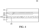
- FIG. 4 is a schematic cross-sectional view of a flexible organic light-emitting display device 200 according to another exemplary embodiment of the present disclosure.
- a flexible organic light-emitting display device 200 according to another exemplary embodiment of the present disclosure will be described focusing on differences from the flexible organic light-emitting display device 100 according to the exemplary embodiment of the present disclosure, and the redundant features will be omitted.
- an adhesive layer 208 of the flexible organic light-emitting display device 200 includes at least two layers.
- a first adhesive layer 218 of the adhesive layer 208 is disposed closer to a first flexible substrate 202.
- a second adhesive layer 228 is disposed closer to a second flexible substrate 210.
- the second adhesive layer 228 contains moisture absorbents 238 (i.e., getters).
- the thickness of the adhesive layer 208 according to the exemplary embodiments of the present disclosure may be larger than the related art adhesive layers with respect to the bending characteristics and strength of the first flexible substrate.
- the adhesive layer 208 cannot sufficiently block moisture permeation, compared to the second flexible substrate 210. Accordingly, moisture may permeate through the side surfaces of the adhesive layer 208.
- the second adhesive layer 228 contains the moisture absorbents 238.
- the moisture absorbents 238 may damage an encapsulation unit 206. Therefore, the first adhesive layer 218 is interposed between the moisture absorbents 238 and the encapsulation unit 206 to protect the encapsulation unit 206 from the moisture absorbents 238.
- a plurality of organic light-emitting pixels 204 is disposed on the first flexible substrate 202.
- the first adhesive layer 218 may have a thickness between 5 ⁇ m and 8 ⁇ m so as to protect the encapsulation unit 206 from the moisture absorbents 238 of the second adhesive layer 228.
- the sum of the thickness of the first adhesive layer 218 and the thickness of the second adhesive layer 228 may be at least 40 ⁇ m to 60 ⁇ m.
- this is merely illustrative and the present disclosure is not limited thereto.
- a flexible organic light-emitting display device may be disposed in a structure capable of scrolling the flexible organic light-emitting display device.
- one side of the flexible organic light-emitting display device is fixed to a cylinder having a diameter such that it may be rolled or unrolled according to the rotation of the cylinder.
- inventive concepts herein are not limited to display devices or screens that are fixed or operatively attached to a cylinder, as other types of support structures that allow different form factors (i.e. opening for usage and closing for stowage, etc.) are possible.
- a flexible organic light-emitting display device includes a first flexible substrate on which a plurality of organic light-emitting pixels is disposed; a second flexible substrate facing the plurality of organic light-emitting pixels on the first flexible substrate; and an adhesive layer configured to adhere the first flexible substrate to the second flexible substrate.
- a neutral plane is configured adjacent to the plurality of organic light-emitting pixels such that the stress by bending is not created when the flexible organic light-emitting display device is rolled toward the first flexible substrate, thereby protecting the organic light-emitting pixels from the stress.
- the first flexible substrate of the flexible organic light-emitting display device is made of a material having a high Young's modulus so that the first flexible substrate can be unrolled flatly. For his reason, the first flexible substrate is made of an etched glass. According to the above-described configuration, there is an advantage in that the flatness of the substrate is maintained during a manufacturing process of the organic light-emitting pixels, so that desired yield and processing conditions can be achieved. In addition, there is an advantage in that a desired curvature radius threshold of the flexible organic light-emitting display device can be achieved since the substrate is etched to a certain thickness after forming the organic light-emitting pixels.
- the adhesive layer of the flexible organic light-emitting display device is made of a material having a Young's modulus larger than a certain value so that it is not deformed when it is rolled into a scroll.
- the adhesive layer has a Young's modulus smaller than that of the first flexible substrate. That is, the Young's modulus of the adhesive layer is smaller than that of the first flexible substrate and is larger than a certain value so that the flexible organic light-emitting display device is not deformed when it is kept in the form of a scroll for long hours.
- the thickness of the adhesive layer of the flexible organic light-emitting display device is determined with respect to the thickness of the first flexible substrate and the strength of the flexible organic light-emitting display device. That is, the adhesive layer has a thickness larger than a certain value in order to achieve a desired strength of the flexible organic light-emitting display device. In addition, the adhesive layer has a thickness smaller than a certain value with respect to the curvature radius threshold of the flexible organic light-emitting display device. That is, the thickness of the adhesive layer is determined in a range that obtains a desired strength at a given thickness of the first flexible substrate without increasing the curvature radius threshold of the flexible organic light-emitting display device.
- the second flexible substrate of the flexible organic light-emitting display device is made of a material having a high Young's modulus value so that the second flexible substrate can be unrolled flatly. Since the second flexible substrate receives tensile stress when it is rolled, the second flexible substrate is made of a material having better durability against tensile stress than that of the first flexible substrate. For this reason, the second flexible substrate is made of a metal material. According to the above-described configuration, it is possible to avoid damage by the tensile stress when the flexible organic light-emitting display device is rolled into a scroll.
- the flexible organic light-emitting display device may be rolled into a circle having a curvature radius larger than the minimum curvature radius that maintains elastic deformation property.
- the first flexible substrate is rolled into a circle having a curvature radius larger than the minimum curvature radius that maintains an elastic deformation property.
- the second flexible substrate is rolled into a circle having a curvature radius larger than the minimum curvature radius that maintains the elastic deformation property.
- elastic deformation refers to a property that allows a layer to restore its original shape as soon as stress is removed even after it is rolled for long hours.
- the adhesive layer between the first and second flexible substrates has an inelastic (anelastic) deformation property.
- inelastic deformation refers to a property that a layer does not restore its original shape even after stress is removed or restores its original shape if it is rolled and stored for a certain period.
- the Young's modulus of the first and second flexible substrates may be larger than that of the adhesive layer.
- the adhesive layer may be made of a polymer.
- the elastic deformation property can be maintained as the first and second flexible substrates are rolled into a circle having a curvature radius larger than the minimum curvature radius that maintains the elastic deformation property.
- the adhesive layer has an inelastic deformation property, and thus it may be deformed after it is rolled for a long-term period.
- the Young's modulus of each of the first and second flexible substrates is larger than that of the adhesive layer, the adhesive layer can restore its flat shape by virtue of the first and second flexible substrates.
- the flexible organic light-emitting display device may maintain the elastic deformation property while having a brittle property and a plastic deformation property.
- the first flexible substrate has the elastic deformation property in general and such property may be changed into a brittle property if a stress above a certain level is exerted thereon.
- the second flexible substrate has the elastic deformation property in general and such property may be changed into a plastic deformation property if a stress above a certain level is exerted thereon.
- brittle property refers to a property that if a layer is deformed by stress, the layer is rarely plastically deformed but is shattered (e.g., breaks).
- plastic deformation refers to a property that has the elastic deformation property in general and such property may be changed into the inelastic deformation property if a stress above a certain level is exerted thereon.
- the first flexible substrate may be rolled such that it receives a stress below a value that causes brittle property. Further, the second flexible substrate may be rolled such that it receives a stress below a value that causes plastic deformation.
- the first flexible substrate is made of glass.
- the second flexible substrate is made of metal.
- the elastic deformation property can be maintained as the first and second flexible substrates are rolled into a circle having a curvature radius larger than the minimum curvature radius that can maintain the elastic deformation property.
- the first flexible substrate has brittle property, it has good resilience, and thus there is an advantage in that the flexible organic light-emitting display device is not deformed even after it is rolled for a long-term period.
- the adhesive layer may be made of an elastomer.
- the term "elastomer” refers to a polymer with elastic deformation property, such as rubber (e.g., a very large deformation that can be restored at a low stress level).
- the Young's modulus E p of the adhesive layer made of an elastomer may be 5 MPa to 100 MPa. That is, elastomer can be easily deformed even with a small stress, and has excellent resilience. Accordingly, if the adhesive layer is made of elastomer, it has very low Young's modulus, and thus there is an advantage in that it does not affect the deformation of the flexible organic light-emitting display device.
- At least a surface of the first flexible substrate may be etched.
- a first surface of the first flexible substrate may be etched, thereby removing a defect, a scratch or damage on the first surface.
- the etched surface may be configured to endure tensile stress. According to the above-described configuration, there is an advantage in that the reliability of the flexible organic light-emitting display device can be improved even if at least one surface of the first flexible substrate is etched.
- both surfaces of the first flexible substrate may be etched.
- a first surface and a second surface of the first flexible substrate may be etched, thereby removing a defect, a scratch or damage on the first and second surfaces may be removed.
- an organic light-emitting display device includes: a first flexible substrate; a second flexible substrate facing the first flexible substrate; a plurality of organic light-emitting pixels on the first flexible substrate and interposed between the first flexible substrate and the second flexible substrate; an encapsulation unit between the first flexible substrate and the second flexible substrate to protect the plurality of organic light-emitting pixels from oxygen and moisture; and an adhesive layer on the encapsulation unit to adhere the first flexible substrate and the second flexible substrate.
- the plurality of organic light-emitting pixels is configured to be adjacent to a neutral plane.
- the adhesive layer has a Young' s modulus that is equal to or larger than a certain value so that the first flexible substrate is not deformed by bending stress if it is retracted in a rolled up form for a certain period of time.
- the thickness of the adhesive layer is determined with respect to the thickness of the first flexible substrate, the curvature radius threshold of the first flexible substrate and the Young's modulus of the adhesive layer.
- the first flexible substrate may be configured to receive compressive stress and the second flexible substrate may be configured to receive tensile stress, such that compressive stress is applied to the first flexible substrate and tensile stress is applied to the second flexible substrate when the first substrate is rolled up.
- the second flexible substrate is made of a material having a higher breaking strength against tensile stress than that of the first flexible substrate.
- the second flexible substrate may be a metal plate having a thickness between 10 ⁇ m and 120 ⁇ m.
- the first flexible substrate may be made of a material having a higher breaking strength against compressive stress than that of the second flexible substrate.
- the first flexible substrate may be an etched glass substrate having a thickness between 30 ⁇ m and 100 ⁇ m.
- the thickness of the adhesive layer may be between 40 ⁇ m and 60 ⁇ m.
- the adhesive layer may further include a first adhesive layer adjacent to the plurality of organic light-emitting pixels, and a second adhesive layer adjacent to the second flexible substrate and containing a moisture absorbent.
- the thickness of the first adhesive layer may be equal to at least 5 ⁇ m, and the thickness of the second adhesive layer may be equal to the thickness of the adhesive layer minus the thickness of the first adhesive layer.
- the adhesive layer may be made of an epoxy resin having the Young's modulus of 900 MPa or higher under cured status, and the plurality of organic light-emitting pixels is configured to be adjacent to a neutral plane.
- the first flexible substrate may be capable of being rolled up to have a curvature radius equal to or larger than a minimum curvature radius that maintains an elastic deformation property
- the second flexible substrate may be rolled into a circle having a curvature radius equal to or larger than a minimum curvature radius that maintains the elastic deformation property
- the adhesive layer may have inelastic deformation property
- the Young's modulus of each of the first flexible substrate and the second flexible substrate may be larger than that of the adhesive layer.
- the first flexible substrate may have a brittle property while having the elastic deformation property
- the first flexible substrate may be capable of being rolled up so that it receives a stress below a value that causes the brittle property
- the second flexible substrate may have a plastic deformation property while having the elastic deformation property
- the second flexible substrate may be capable of being rolled up so that it receives a stress below a value that causes the plastic deformation property.
- the adhesive layer may be made of an elastomer and may have the Young's modulus between 5 MPa and 100 MPa.
- a surface of the first flexible substrate may be etched, and the etched surface may be configured to receive tensile stress.
- an organic light-emitting display device includes: a first flexible substrate; a second flexible substrate facing the first flexible substrate; a plurality of organic light-emitting pixels on the first flexible substrate and between the first flexible substrate and the second flexible substrate; an encapsulation unit between the first flexible substrate and the second flexible substrate to protect the plurality of organic light-emitting pixels from oxygen and moisture; and an adhesive layer on the encapsulation unit to adhere the first flexible substrate and the second flexible substrate together.
- the first flexible substrate may be capable of being rolled up to have a curvature radius equal to or larger than a minimum curvature radius that maintains an elastic deformation property
- the second flexible substrate may be capable of being rolled up to have a curvature radius equal to or larger than a minimum curvature radius that maintains an elastic deformation property
- the adhesive layer may have an elastic deformation property
- each of the first and second flexible substrates may have a Young's modulus that is larger than that of the adhesive layer.
Landscapes
- Physics & Mathematics (AREA)
- Optics & Photonics (AREA)
- Electroluminescent Light Sources (AREA)
Claims (11)
- Flexible organische lichtemittierende Anzeigevorrichtung (100, 200), umfassend:ein erstes flexibles Substrat (102, 202);ein zweites flexibles Substrat (110, 210), das dem ersten flexiblen Substrat (102, 202) zugewandt ist;mehrere organische lichtemittierende Pixel (104, 204) auf dem ersten flexiblen Substrat (102, 202), und die zwischen dem ersten flexiblen Substrat (102, 202) und dem zweiten flexiblen Substrat (110, 210) angeordnet sind;eine Verkapselungseinheit (106, 206) zwischen den mehreren organischen lichtemittierenden Pixeln (104, 204) und dem zweiten flexiblen Substrat (110, 210), und die konfiguriert ist, die mehreren organischen lichtemittierenden Pixel (104, 204) vor Sauerstoff und Feuchtigkeit zu schützen; undeine Klebeschicht (108, 208) auf der Verkapselungseinheit (106, 206), die das erste flexible Substrat (102, 202) und das zweite flexible Substrat (110, 210) aneinander befestigt,dadurch gekennzeichnet, dass der Elastizitätsmodul des ersten flexiblen Substrats (102, 202) größer ist als der der Klebeschicht (108, 208), und dass der Elastizitätsmodul des zweiten flexiblen Substrats (110, 210) größer ist als der der Klebeschicht (108, 208),wobei das zweite flexible Substrat (110, 210) eine Metallplatte mit einer höheren Bruchfestigkeit gegen Zugspannung als ein Material des ersten flexiblen Substrats (102, 202) aufweist,wobei das erste flexible Substrat (102, 202) ein Glassubstrat aufweist.
- Flexible organische lichtemittierende Anzeigevorrichtung (100, 200) nach Anspruch 1, wobei das erste flexible Substrat (102, 202) konfiguriert ist, eine Druckspannung aufzunehmen, und das zweite flexible Substrat (110, 210) konfiguriert ist, eine Zugspannung aufzunehmen, wenn das erste flexible Substrat (102, 202) aufgerollt wird.
- Flexible organische lichtemittierende Anzeigevorrichtung (100, 200) nach einem der vorhergehenden Ansprüche, wobei das zweite flexible Substrat (110, 210) eine Dicke zwischen 10 µm und 120 µm aufweist.
- Flexible organische lichtemittierende Anzeigevorrichtung (100, 200) nach einem der vorhergehenden Ansprüche, wobei das erste flexible Substrat (102, 202) aus einem Material hergestellt ist, das eine höhere Bruchfestigkeit gegen Druckspannung aufweist als die des zweiten flexiblen Substrats (110, 210).
- Flexible organische lichtemittierende Anzeigevorrichtung (100, 200) nach einem der vorhergehenden Ansprüche, wobei das erste flexible Substrat (102, 202) eine Dicke zwischen 30 µm und 100 µm aufweist.
- Flexible organische lichtemittierende Anzeigevorrichtung (100, 200) nach einem der vorhergehenden Ansprüche, wobei die Dicke der Klebeschicht (108, 208) zwischen 40 µm und 60 µm beträgt.
- Flexible organische lichtemittierende Anzeigevorrichtung (200) nach einem der vorhergehenden Ansprüche, wobei die Klebeschicht (208) eine erste Klebeschicht (218) benachbart zu den mehreren organischen lichtemittierenden Pixeln (204) und eine zweite Klebeschicht (228) benachbart zu dem zweiten flexiblen Substrat (210) umfasst, wobei die zweite Klebeschicht (228) ein Feuchtigkeitsabsorptionsmittel (238) enthält.
- Flexible organische lichtemittierende Anzeigevorrichtung (200) nach Anspruch 7, wobei eine Dicke der ersten Klebeschicht (218) mindestens 5 µm beträgt.
- Flexible organische lichtemittierende Anzeigevorrichtung (100, 200) nach einem der vorhergehenden Ansprüche, wobei die Klebeschicht (108, 208) ein Epoxidharz oder ein Elastomer aufweist.
- Flexible organische lichtemittierende Anzeigevorrichtung (100, 200) nach einem der vorhergehenden Ansprüche, wobei die Klebeschicht (108, 208) in einem ausgehärteten Zustand einen Elastizitätsmodul von 900 MPa oder höher aufweist oder wobei die Klebeschicht (108, 208) einen Elastizitätsmodul zwischen 5 MPa und 100 Mpa aufweist.
- Flexible organische lichtemittierende Anzeigevorrichtung (100, 200) nach einem der vorhergehenden Ansprüche, wobei das erste flexible Substrat (102, 202) eine geätzte Oberfläche gegenüber einer Oberfläche des ersten flexiblen Substrats (102, 202), auf dem die mehreren organischen lichtemittierenden Pixel (104, 204) angeordnet sind, aufweist, wobei die mehreren organischen lichtemittierenden Pixel (104, 204) benachbart zu einer neutralen Ebene (NP) der flexiblen organischen lichtemittierenden Anzeigevorrichtung (100, 200) sind.
Priority Applications (1)
| Application Number | Priority Date | Filing Date | Title |
|---|---|---|---|
| EP19191487.8A EP3598514B1 (de) | 2015-08-31 | 2016-08-30 | Organische lichtemittierende anzeigevorrichtung |
Applications Claiming Priority (2)
| Application Number | Priority Date | Filing Date | Title |
|---|---|---|---|
| KR20150123243 | 2015-08-31 | ||
| KR1020150184885A KR102028008B1 (ko) | 2015-08-31 | 2015-12-23 | 유기 발광 표시장치 |
Related Child Applications (2)
| Application Number | Title | Priority Date | Filing Date |
|---|---|---|---|
| EP19191487.8A Division EP3598514B1 (de) | 2015-08-31 | 2016-08-30 | Organische lichtemittierende anzeigevorrichtung |
| EP19191487.8A Division-Into EP3598514B1 (de) | 2015-08-31 | 2016-08-30 | Organische lichtemittierende anzeigevorrichtung |
Publications (2)
| Publication Number | Publication Date |
|---|---|
| EP3136459A1 EP3136459A1 (de) | 2017-03-01 |
| EP3136459B1 true EP3136459B1 (de) | 2019-10-09 |
Family
ID=56893718
Family Applications (2)
| Application Number | Title | Priority Date | Filing Date |
|---|---|---|---|
| EP19191487.8A Active EP3598514B1 (de) | 2015-08-31 | 2016-08-30 | Organische lichtemittierende anzeigevorrichtung |
| EP16186330.3A Active EP3136459B1 (de) | 2015-08-31 | 2016-08-30 | Flexible organische lichtemittierende anzeigevorrichtung |
Family Applications Before (1)
| Application Number | Title | Priority Date | Filing Date |
|---|---|---|---|
| EP19191487.8A Active EP3598514B1 (de) | 2015-08-31 | 2016-08-30 | Organische lichtemittierende anzeigevorrichtung |
Country Status (3)
| Country | Link |
|---|---|
| US (4) | US9960375B2 (de) |
| EP (2) | EP3598514B1 (de) |
| CN (2) | CN110071141B (de) |
Families Citing this family (34)
| Publication number | Priority date | Publication date | Assignee | Title |
|---|---|---|---|---|
| US9960375B2 (en) * | 2015-08-31 | 2018-05-01 | Lg Display Co., Ltd. | Organic light-emitting display device |
| KR102455724B1 (ko) * | 2016-04-21 | 2022-10-19 | 삼성디스플레이 주식회사 | 플렉서블 표시 장치 |
| KR102717868B1 (ko) | 2016-09-13 | 2024-10-15 | 삼성디스플레이 주식회사 | 표시 장치 |
| KR102505265B1 (ko) * | 2017-06-23 | 2023-03-06 | 삼성디스플레이 주식회사 | 전자 장치 |
| US10649267B2 (en) | 2017-07-19 | 2020-05-12 | Innolux Corporation | Display device and manufacturing method thereof |
| CN109427980B (zh) * | 2017-08-24 | 2021-07-27 | 上海和辉光电股份有限公司 | 一种柔性显示面板及柔性显示装置 |
| KR102414084B1 (ko) * | 2017-10-11 | 2022-06-28 | 코닝 인코포레이티드 | 충격 저항성 및 굽힘 저항성을 가지는 폴더블 전자 장치 모듈들 |
| JP7056834B2 (ja) | 2017-10-20 | 2022-04-19 | 京東方科技集團股▲ふん▼有限公司 | フレキシブル表示パネルおよびフレキシブル表示装置 |
| CN109712529A (zh) * | 2017-10-26 | 2019-05-03 | 元太科技工业股份有限公司 | 可挠性电子装置 |
| CN107871453A (zh) * | 2017-10-31 | 2018-04-03 | 云谷(固安)科技有限公司 | 一种柔性显示模组及其制备方法 |
| WO2019090731A1 (zh) * | 2017-11-10 | 2019-05-16 | 深圳市柔宇科技有限公司 | 柔性背板及柔性显示装置、制备方法 |
| CN108108058A (zh) * | 2018-01-05 | 2018-06-01 | 业成科技(成都)有限公司 | 触控感测装置 |
| CN108279516B (zh) * | 2018-02-01 | 2021-10-15 | 上海天马微电子有限公司 | 一种显示面板及显示装置 |
| EP3608964B1 (de) * | 2018-08-08 | 2022-05-11 | LG Display Co., Ltd. | Dehnbare anzeigevorrichtung |
| KR102465207B1 (ko) | 2018-09-19 | 2022-11-09 | 삼성디스플레이 주식회사 | 보호 필름 및 그것을 포함하는 전자 기기 |
| JP2020088271A (ja) * | 2018-11-29 | 2020-06-04 | 株式会社ジャパンディスプレイ | フレキシブル基板 |
| KR102639989B1 (ko) * | 2018-12-28 | 2024-02-22 | 엘지디스플레이 주식회사 | 플렉서블 표시장치 |
| KR102068685B1 (ko) * | 2019-03-11 | 2020-01-21 | (주)유티아이 | 플렉시블 커버 윈도우 |
| CN110060573B (zh) * | 2019-04-22 | 2020-12-29 | 昆山国显光电有限公司 | 柔性模组结构及显示装置 |
| KR102707459B1 (ko) * | 2019-07-29 | 2024-09-20 | 엘지전자 주식회사 | 롤러블 디스플레이 디바이스 |
| CN110634396B (zh) * | 2019-08-16 | 2022-07-08 | 云谷(固安)科技有限公司 | 一种显示面板 |
| CN112753010B (zh) * | 2019-08-19 | 2024-03-15 | 京东方科技集团股份有限公司 | 可折叠显示屏及其组装方法、显示装置 |
| KR102867466B1 (ko) * | 2020-04-16 | 2025-10-02 | 삼성디스플레이 주식회사 | 표시 장치, 표시 장치의 제조 장치 및 표시 장치의 제조 방법 |
| EP3915959B1 (de) | 2020-05-29 | 2023-10-11 | Corning Incorporated | Rollbare oder faltbare glasscheibe für fahrzeuginnenraumsysteme |
| CN111833740B (zh) | 2020-06-16 | 2022-08-19 | 京东方科技集团股份有限公司 | 柔性显示装置 |
| CN111862808A (zh) * | 2020-06-28 | 2020-10-30 | 京东方科技集团股份有限公司 | 显示盖板及其制备方法和柔性显示装置 |
| JP2022028479A (ja) * | 2020-08-03 | 2022-02-16 | 日東電工株式会社 | 複層構造体 |
| CN112018263B (zh) * | 2020-08-07 | 2022-03-29 | 武汉华星光电半导体显示技术有限公司 | 一种柔性显示装置 |
| CN120220537A (zh) * | 2021-06-01 | 2025-06-27 | 群创光电股份有限公司 | 显示装置 |
| CN114241920B (zh) * | 2021-12-30 | 2024-03-22 | 深圳市华星光电半导体显示技术有限公司 | 柔性显示面板及显示装置 |
| CN114155791B (zh) * | 2022-01-24 | 2024-01-23 | 合肥维信诺科技有限公司 | 显示装置 |
| CN115691338B (zh) * | 2022-11-10 | 2024-09-03 | 业成光电(深圳)有限公司 | 显示面板及显示装置 |
| CN117037619B (zh) * | 2023-08-29 | 2025-10-17 | 合肥维信诺科技有限公司 | 显示模组及显示装置 |
| CN117409675B (zh) * | 2023-12-12 | 2024-04-19 | 荣耀终端有限公司 | 可折叠的显示模组及电子设备 |
Citations (1)
| Publication number | Priority date | Publication date | Assignee | Title |
|---|---|---|---|---|
| US20030170444A1 (en) * | 2002-03-05 | 2003-09-11 | Stewart Steven L. | Attachment of surface mount devices to printed circuit boards using a thermoplastic adhesive |
Family Cites Families (8)
| Publication number | Priority date | Publication date | Assignee | Title |
|---|---|---|---|---|
| KR100888480B1 (ko) * | 2007-05-23 | 2009-03-12 | 삼성전자주식회사 | 전기 활성 고분자를 이용한 반사 유닛 및 플렉서블디스플레이 |
| CN102902109A (zh) | 2012-10-29 | 2013-01-30 | 友达光电股份有限公司 | 一种可挠性显示面板 |
| EP2966937B1 (de) | 2013-03-08 | 2022-05-04 | Pioneer Corporation | Lichtemittierendes element |
| KR102065589B1 (ko) * | 2013-04-17 | 2020-01-14 | 삼성디스플레이 주식회사 | 플렉서블 디스플레이 장치의 제조방법 |
| CN103346163B (zh) * | 2013-06-19 | 2016-12-28 | 青岛海信电器股份有限公司 | 一种柔性显示装置及其制造方法 |
| KR20150021000A (ko) | 2013-08-19 | 2015-02-27 | 가부시키가이샤 한도오따이 에네루기 켄큐쇼 | 표시 장치 |
| KR20150045329A (ko) | 2013-10-18 | 2015-04-28 | 삼성디스플레이 주식회사 | 유기 발광 장치 |
| US9960375B2 (en) * | 2015-08-31 | 2018-05-01 | Lg Display Co., Ltd. | Organic light-emitting display device |
-
2016
- 2016-08-26 US US15/248,852 patent/US9960375B2/en active Active
- 2016-08-30 EP EP19191487.8A patent/EP3598514B1/de active Active
- 2016-08-30 CN CN201910129164.7A patent/CN110071141B/zh active Active
- 2016-08-30 EP EP16186330.3A patent/EP3136459B1/de active Active
- 2016-08-30 CN CN201610770322.3A patent/CN106505156B/zh active Active
-
2018
- 2018-03-21 US US15/927,692 patent/US10263204B2/en active Active
-
2019
- 2019-02-21 US US16/281,787 patent/US10505131B2/en active Active
- 2019-11-19 US US16/688,778 patent/US10790460B2/en active Active
Patent Citations (1)
| Publication number | Priority date | Publication date | Assignee | Title |
|---|---|---|---|---|
| US20030170444A1 (en) * | 2002-03-05 | 2003-09-11 | Stewart Steven L. | Attachment of surface mount devices to printed circuit boards using a thermoplastic adhesive |
Also Published As
| Publication number | Publication date |
|---|---|
| US10790460B2 (en) | 2020-09-29 |
| CN110071141A (zh) | 2019-07-30 |
| EP3598514B1 (de) | 2021-12-29 |
| US20190181366A1 (en) | 2019-06-13 |
| US20180212170A1 (en) | 2018-07-26 |
| CN106505156A (zh) | 2017-03-15 |
| US10505131B2 (en) | 2019-12-10 |
| US20200111979A1 (en) | 2020-04-09 |
| EP3598514A1 (de) | 2020-01-22 |
| US10263204B2 (en) | 2019-04-16 |
| US20170062741A1 (en) | 2017-03-02 |
| CN110071141B (zh) | 2022-11-01 |
| CN106505156B (zh) | 2019-03-29 |
| US9960375B2 (en) | 2018-05-01 |
| EP3136459A1 (de) | 2017-03-01 |
Similar Documents
| Publication | Publication Date | Title |
|---|---|---|
| US10790460B2 (en) | Organic light-emitting display device | |
| KR102463601B1 (ko) | 유기 발광 표시장치 | |
| EP2879197B1 (de) | Organische lichtemittierende Anzeigevorrichtung und Verfahren zur Herstellung davon | |
| US11108014B2 (en) | Flexible display device | |
| US20190346591A1 (en) | Replaceable cover lens for flexible display | |
| EP2950363B1 (de) | Organische lichtemittierende anzeigevorrichtung | |
| JP2017187705A (ja) | 表示装置 | |
| CN105313429B (zh) | 层压装置及层压方法 | |
| CN109728189B (zh) | 显示面板和显示装置 | |
| EP3521914B1 (de) | Anzeigevorrichtung und herstellungsverfahren für basisfolie | |
| US11332587B2 (en) | Window for display device and display device including the window | |
| KR101038329B1 (ko) | 플렉시블 디스플레이 기판 | |
| US11489126B2 (en) | Protection of foldable electronics | |
| US20240224722A1 (en) | Cover module and display device including the same |
Legal Events
| Date | Code | Title | Description |
|---|---|---|---|
| PUAI | Public reference made under article 153(3) epc to a published international application that has entered the european phase |
Free format text: ORIGINAL CODE: 0009012 |
|
| STAA | Information on the status of an ep patent application or granted ep patent |
Free format text: STATUS: REQUEST FOR EXAMINATION WAS MADE |
|
| 17P | Request for examination filed |
Effective date: 20160830 |
|
| AK | Designated contracting states |
Kind code of ref document: A1 Designated state(s): AL AT BE BG CH CY CZ DE DK EE ES FI FR GB GR HR HU IE IS IT LI LT LU LV MC MK MT NL NO PL PT RO RS SE SI SK SM TR |
|
| AX | Request for extension of the european patent |
Extension state: BA ME |
|
| RBV | Designated contracting states (corrected) |
Designated state(s): AL AT BE BG CH CY CZ DE DK EE ES FI FR GB GR HR HU IE IS IT LI LT LU LV MC MK MT NL NO PL PT RO RS SE SI SK SM TR |
|
| STAA | Information on the status of an ep patent application or granted ep patent |
Free format text: STATUS: EXAMINATION IS IN PROGRESS |
|
| 17Q | First examination report despatched |
Effective date: 20180425 |
|
| GRAP | Despatch of communication of intention to grant a patent |
Free format text: ORIGINAL CODE: EPIDOSNIGR1 |
|
| STAA | Information on the status of an ep patent application or granted ep patent |
Free format text: STATUS: GRANT OF PATENT IS INTENDED |
|
| INTG | Intention to grant announced |
Effective date: 20190322 |
|
| GRAS | Grant fee paid |
Free format text: ORIGINAL CODE: EPIDOSNIGR3 |
|
| GRAA | (expected) grant |
Free format text: ORIGINAL CODE: 0009210 |
|
| STAA | Information on the status of an ep patent application or granted ep patent |
Free format text: STATUS: THE PATENT HAS BEEN GRANTED |
|
| AK | Designated contracting states |
Kind code of ref document: B1 Designated state(s): AL AT BE BG CH CY CZ DE DK EE ES FI FR GB GR HR HU IE IS IT LI LT LU LV MC MK MT NL NO PL PT RO RS SE SI SK SM TR |
|
| REG | Reference to a national code |
Ref country code: GB Ref legal event code: FG4D |
|
| REG | Reference to a national code |
Ref country code: CH Ref legal event code: EP |
|
| REG | Reference to a national code |
Ref country code: IE Ref legal event code: FG4D |
|
| REG | Reference to a national code |
Ref country code: DE Ref legal event code: R096 Ref document number: 602016022010 Country of ref document: DE |
|
| REG | Reference to a national code |
Ref country code: AT Ref legal event code: REF Ref document number: 1189840 Country of ref document: AT Kind code of ref document: T Effective date: 20191115 |
|
| REG | Reference to a national code |
Ref country code: NL Ref legal event code: MP Effective date: 20191009 |
|
| REG | Reference to a national code |
Ref country code: LT Ref legal event code: MG4D |
|
| REG | Reference to a national code |
Ref country code: AT Ref legal event code: MK05 Ref document number: 1189840 Country of ref document: AT Kind code of ref document: T Effective date: 20191009 |
|
| PG25 | Lapsed in a contracting state [announced via postgrant information from national office to epo] |
Ref country code: ES Free format text: LAPSE BECAUSE OF FAILURE TO SUBMIT A TRANSLATION OF THE DESCRIPTION OR TO PAY THE FEE WITHIN THE PRESCRIBED TIME-LIMIT Effective date: 20191009 Ref country code: PT Free format text: LAPSE BECAUSE OF FAILURE TO SUBMIT A TRANSLATION OF THE DESCRIPTION OR TO PAY THE FEE WITHIN THE PRESCRIBED TIME-LIMIT Effective date: 20200210 Ref country code: GR Free format text: LAPSE BECAUSE OF FAILURE TO SUBMIT A TRANSLATION OF THE DESCRIPTION OR TO PAY THE FEE WITHIN THE PRESCRIBED TIME-LIMIT Effective date: 20200110 Ref country code: AT Free format text: LAPSE BECAUSE OF FAILURE TO SUBMIT A TRANSLATION OF THE DESCRIPTION OR TO PAY THE FEE WITHIN THE PRESCRIBED TIME-LIMIT Effective date: 20191009 Ref country code: NL Free format text: LAPSE BECAUSE OF FAILURE TO SUBMIT A TRANSLATION OF THE DESCRIPTION OR TO PAY THE FEE WITHIN THE PRESCRIBED TIME-LIMIT Effective date: 20191009 Ref country code: BG Free format text: LAPSE BECAUSE OF FAILURE TO SUBMIT A TRANSLATION OF THE DESCRIPTION OR TO PAY THE FEE WITHIN THE PRESCRIBED TIME-LIMIT Effective date: 20200109 Ref country code: FI Free format text: LAPSE BECAUSE OF FAILURE TO SUBMIT A TRANSLATION OF THE DESCRIPTION OR TO PAY THE FEE WITHIN THE PRESCRIBED TIME-LIMIT Effective date: 20191009 Ref country code: LT Free format text: LAPSE BECAUSE OF FAILURE TO SUBMIT A TRANSLATION OF THE DESCRIPTION OR TO PAY THE FEE WITHIN THE PRESCRIBED TIME-LIMIT Effective date: 20191009 Ref country code: PL Free format text: LAPSE BECAUSE OF FAILURE TO SUBMIT A TRANSLATION OF THE DESCRIPTION OR TO PAY THE FEE WITHIN THE PRESCRIBED TIME-LIMIT Effective date: 20191009 Ref country code: LV Free format text: LAPSE BECAUSE OF FAILURE TO SUBMIT A TRANSLATION OF THE DESCRIPTION OR TO PAY THE FEE WITHIN THE PRESCRIBED TIME-LIMIT Effective date: 20191009 Ref country code: SE Free format text: LAPSE BECAUSE OF FAILURE TO SUBMIT A TRANSLATION OF THE DESCRIPTION OR TO PAY THE FEE WITHIN THE PRESCRIBED TIME-LIMIT Effective date: 20191009 Ref country code: NO Free format text: LAPSE BECAUSE OF FAILURE TO SUBMIT A TRANSLATION OF THE DESCRIPTION OR TO PAY THE FEE WITHIN THE PRESCRIBED TIME-LIMIT Effective date: 20200109 |
|
| PG25 | Lapsed in a contracting state [announced via postgrant information from national office to epo] |
Ref country code: RS Free format text: LAPSE BECAUSE OF FAILURE TO SUBMIT A TRANSLATION OF THE DESCRIPTION OR TO PAY THE FEE WITHIN THE PRESCRIBED TIME-LIMIT Effective date: 20191009 Ref country code: HR Free format text: LAPSE BECAUSE OF FAILURE TO SUBMIT A TRANSLATION OF THE DESCRIPTION OR TO PAY THE FEE WITHIN THE PRESCRIBED TIME-LIMIT Effective date: 20191009 Ref country code: IS Free format text: LAPSE BECAUSE OF FAILURE TO SUBMIT A TRANSLATION OF THE DESCRIPTION OR TO PAY THE FEE WITHIN THE PRESCRIBED TIME-LIMIT Effective date: 20200224 |
|
| PG25 | Lapsed in a contracting state [announced via postgrant information from national office to epo] |
Ref country code: AL Free format text: LAPSE BECAUSE OF FAILURE TO SUBMIT A TRANSLATION OF THE DESCRIPTION OR TO PAY THE FEE WITHIN THE PRESCRIBED TIME-LIMIT Effective date: 20191009 |
|
| REG | Reference to a national code |
Ref country code: DE Ref legal event code: R097 Ref document number: 602016022010 Country of ref document: DE |
|
| PG2D | Information on lapse in contracting state deleted |
Ref country code: IS |
|
| PG25 | Lapsed in a contracting state [announced via postgrant information from national office to epo] |
Ref country code: RO Free format text: LAPSE BECAUSE OF FAILURE TO SUBMIT A TRANSLATION OF THE DESCRIPTION OR TO PAY THE FEE WITHIN THE PRESCRIBED TIME-LIMIT Effective date: 20191009 Ref country code: CZ Free format text: LAPSE BECAUSE OF FAILURE TO SUBMIT A TRANSLATION OF THE DESCRIPTION OR TO PAY THE FEE WITHIN THE PRESCRIBED TIME-LIMIT Effective date: 20191009 Ref country code: EE Free format text: LAPSE BECAUSE OF FAILURE TO SUBMIT A TRANSLATION OF THE DESCRIPTION OR TO PAY THE FEE WITHIN THE PRESCRIBED TIME-LIMIT Effective date: 20191009 Ref country code: DK Free format text: LAPSE BECAUSE OF FAILURE TO SUBMIT A TRANSLATION OF THE DESCRIPTION OR TO PAY THE FEE WITHIN THE PRESCRIBED TIME-LIMIT Effective date: 20191009 Ref country code: IS Free format text: LAPSE BECAUSE OF FAILURE TO SUBMIT A TRANSLATION OF THE DESCRIPTION OR TO PAY THE FEE WITHIN THE PRESCRIBED TIME-LIMIT Effective date: 20200209 |
|
| PLBE | No opposition filed within time limit |
Free format text: ORIGINAL CODE: 0009261 |
|
| STAA | Information on the status of an ep patent application or granted ep patent |
Free format text: STATUS: NO OPPOSITION FILED WITHIN TIME LIMIT |
|
| PG25 | Lapsed in a contracting state [announced via postgrant information from national office to epo] |
Ref country code: SK Free format text: LAPSE BECAUSE OF FAILURE TO SUBMIT A TRANSLATION OF THE DESCRIPTION OR TO PAY THE FEE WITHIN THE PRESCRIBED TIME-LIMIT Effective date: 20191009 Ref country code: IT Free format text: LAPSE BECAUSE OF FAILURE TO SUBMIT A TRANSLATION OF THE DESCRIPTION OR TO PAY THE FEE WITHIN THE PRESCRIBED TIME-LIMIT Effective date: 20191009 Ref country code: SM Free format text: LAPSE BECAUSE OF FAILURE TO SUBMIT A TRANSLATION OF THE DESCRIPTION OR TO PAY THE FEE WITHIN THE PRESCRIBED TIME-LIMIT Effective date: 20191009 |
|
| 26N | No opposition filed |
Effective date: 20200710 |
|
| PG25 | Lapsed in a contracting state [announced via postgrant information from national office to epo] |
Ref country code: SI Free format text: LAPSE BECAUSE OF FAILURE TO SUBMIT A TRANSLATION OF THE DESCRIPTION OR TO PAY THE FEE WITHIN THE PRESCRIBED TIME-LIMIT Effective date: 20191009 |
|
| PG25 | Lapsed in a contracting state [announced via postgrant information from national office to epo] |
Ref country code: MC Free format text: LAPSE BECAUSE OF FAILURE TO SUBMIT A TRANSLATION OF THE DESCRIPTION OR TO PAY THE FEE WITHIN THE PRESCRIBED TIME-LIMIT Effective date: 20191009 |
|
| REG | Reference to a national code |
Ref country code: CH Ref legal event code: PL |
|
| PG25 | Lapsed in a contracting state [announced via postgrant information from national office to epo] |
Ref country code: LU Free format text: LAPSE BECAUSE OF NON-PAYMENT OF DUE FEES Effective date: 20200830 Ref country code: LI Free format text: LAPSE BECAUSE OF NON-PAYMENT OF DUE FEES Effective date: 20200831 Ref country code: CH Free format text: LAPSE BECAUSE OF NON-PAYMENT OF DUE FEES Effective date: 20200831 |
|
| REG | Reference to a national code |
Ref country code: BE Ref legal event code: MM Effective date: 20200831 |
|
| PG25 | Lapsed in a contracting state [announced via postgrant information from national office to epo] |
Ref country code: BE Free format text: LAPSE BECAUSE OF NON-PAYMENT OF DUE FEES Effective date: 20200831 Ref country code: IE Free format text: LAPSE BECAUSE OF NON-PAYMENT OF DUE FEES Effective date: 20200830 |
|
| PG25 | Lapsed in a contracting state [announced via postgrant information from national office to epo] |
Ref country code: TR Free format text: LAPSE BECAUSE OF FAILURE TO SUBMIT A TRANSLATION OF THE DESCRIPTION OR TO PAY THE FEE WITHIN THE PRESCRIBED TIME-LIMIT Effective date: 20191009 Ref country code: MT Free format text: LAPSE BECAUSE OF FAILURE TO SUBMIT A TRANSLATION OF THE DESCRIPTION OR TO PAY THE FEE WITHIN THE PRESCRIBED TIME-LIMIT Effective date: 20191009 Ref country code: CY Free format text: LAPSE BECAUSE OF FAILURE TO SUBMIT A TRANSLATION OF THE DESCRIPTION OR TO PAY THE FEE WITHIN THE PRESCRIBED TIME-LIMIT Effective date: 20191009 |
|
| PG25 | Lapsed in a contracting state [announced via postgrant information from national office to epo] |
Ref country code: MK Free format text: LAPSE BECAUSE OF FAILURE TO SUBMIT A TRANSLATION OF THE DESCRIPTION OR TO PAY THE FEE WITHIN THE PRESCRIBED TIME-LIMIT Effective date: 20191009 |
|
| REG | Reference to a national code |
Ref country code: DE Ref legal event code: R079 Ref document number: 602016022010 Country of ref document: DE Free format text: PREVIOUS MAIN CLASS: H01L0051000000 Ipc: H10K0099000000 |
|
| REG | Reference to a national code |
Ref country code: DE Ref legal event code: R082 Ref document number: 602016022010 Country of ref document: DE Representative=s name: TER MEER STEINMEISTER & PARTNER PATENTANWAELTE, DE |
|
| PGFP | Annual fee paid to national office [announced via postgrant information from national office to epo] |
Ref country code: DE Payment date: 20250624 Year of fee payment: 10 |
|
| PGFP | Annual fee paid to national office [announced via postgrant information from national office to epo] |
Ref country code: GB Payment date: 20260624 Year of fee payment: 11 |
|
| PGFP | Annual fee paid to national office [announced via postgrant information from national office to epo] |
Ref country code: FR Payment date: 20260625 Year of fee payment: 11 |