EP3136366A1 - Information presentation device and information presentation method - Google Patents
Information presentation device and information presentation method Download PDFInfo
- Publication number
- EP3136366A1 EP3136366A1 EP14889810.9A EP14889810A EP3136366A1 EP 3136366 A1 EP3136366 A1 EP 3136366A1 EP 14889810 A EP14889810 A EP 14889810A EP 3136366 A1 EP3136366 A1 EP 3136366A1
- Authority
- EP
- European Patent Office
- Prior art keywords
- information
- action
- driver
- driving
- vehicle
- Prior art date
- Legal status (The legal status is an assumption and is not a legal conclusion. Google has not performed a legal analysis and makes no representation as to the accuracy of the status listed.)
- Granted
Links
Images


Classifications
-
- B—PERFORMING OPERATIONS; TRANSPORTING
- B60—VEHICLES IN GENERAL
- B60W—CONJOINT CONTROL OF VEHICLE SUB-UNITS OF DIFFERENT TYPE OR DIFFERENT FUNCTION; CONTROL SYSTEMS SPECIALLY ADAPTED FOR HYBRID VEHICLES; ROAD VEHICLE DRIVE CONTROL SYSTEMS FOR PURPOSES NOT RELATED TO THE CONTROL OF A PARTICULAR SUB-UNIT
- B60W60/00—Drive control systems specially adapted for autonomous road vehicles
- B60W60/005—Handover processes
- B60W60/0059—Estimation of the risk associated with autonomous or manual driving, e.g. situation too complex, sensor failure or driver incapacity
-
- B—PERFORMING OPERATIONS; TRANSPORTING
- B60—VEHICLES IN GENERAL
- B60R—VEHICLES, VEHICLE FITTINGS, OR VEHICLE PARTS, NOT OTHERWISE PROVIDED FOR
- B60R16/00—Electric or fluid circuits specially adapted for vehicles and not otherwise provided for; Arrangement of elements of electric or fluid circuits specially adapted for vehicles and not otherwise provided for
- B60R16/02—Electric or fluid circuits specially adapted for vehicles and not otherwise provided for; Arrangement of elements of electric or fluid circuits specially adapted for vehicles and not otherwise provided for electric constitutive elements
-
- B—PERFORMING OPERATIONS; TRANSPORTING
- B60—VEHICLES IN GENERAL
- B60W—CONJOINT CONTROL OF VEHICLE SUB-UNITS OF DIFFERENT TYPE OR DIFFERENT FUNCTION; CONTROL SYSTEMS SPECIALLY ADAPTED FOR HYBRID VEHICLES; ROAD VEHICLE DRIVE CONTROL SYSTEMS FOR PURPOSES NOT RELATED TO THE CONTROL OF A PARTICULAR SUB-UNIT
- B60W40/00—Estimation or calculation of non-directly measurable driving parameters for road vehicle drive control systems not related to the control of a particular sub unit, e.g. by using mathematical models
- B60W40/08—Estimation or calculation of non-directly measurable driving parameters for road vehicle drive control systems not related to the control of a particular sub unit, e.g. by using mathematical models related to drivers or passengers
-
- B—PERFORMING OPERATIONS; TRANSPORTING
- B60—VEHICLES IN GENERAL
- B60W—CONJOINT CONTROL OF VEHICLE SUB-UNITS OF DIFFERENT TYPE OR DIFFERENT FUNCTION; CONTROL SYSTEMS SPECIALLY ADAPTED FOR HYBRID VEHICLES; ROAD VEHICLE DRIVE CONTROL SYSTEMS FOR PURPOSES NOT RELATED TO THE CONTROL OF A PARTICULAR SUB-UNIT
- B60W50/00—Details of control systems for road vehicle drive control not related to the control of a particular sub-unit, e.g. process diagnostic or vehicle driver interfaces
- B60W50/0097—Predicting future conditions
-
- B—PERFORMING OPERATIONS; TRANSPORTING
- B60—VEHICLES IN GENERAL
- B60W—CONJOINT CONTROL OF VEHICLE SUB-UNITS OF DIFFERENT TYPE OR DIFFERENT FUNCTION; CONTROL SYSTEMS SPECIALLY ADAPTED FOR HYBRID VEHICLES; ROAD VEHICLE DRIVE CONTROL SYSTEMS FOR PURPOSES NOT RELATED TO THE CONTROL OF A PARTICULAR SUB-UNIT
- B60W50/00—Details of control systems for road vehicle drive control not related to the control of a particular sub-unit, e.g. process diagnostic or vehicle driver interfaces
- B60W50/08—Interaction between the driver and the control system
- B60W50/082—Selecting or switching between different modes of propelling
-
- B—PERFORMING OPERATIONS; TRANSPORTING
- B60—VEHICLES IN GENERAL
- B60W—CONJOINT CONTROL OF VEHICLE SUB-UNITS OF DIFFERENT TYPE OR DIFFERENT FUNCTION; CONTROL SYSTEMS SPECIALLY ADAPTED FOR HYBRID VEHICLES; ROAD VEHICLE DRIVE CONTROL SYSTEMS FOR PURPOSES NOT RELATED TO THE CONTROL OF A PARTICULAR SUB-UNIT
- B60W50/00—Details of control systems for road vehicle drive control not related to the control of a particular sub-unit, e.g. process diagnostic or vehicle driver interfaces
- B60W50/08—Interaction between the driver and the control system
- B60W50/14—Means for informing the driver, warning the driver or prompting a driver intervention
-
- B—PERFORMING OPERATIONS; TRANSPORTING
- B60—VEHICLES IN GENERAL
- B60W—CONJOINT CONTROL OF VEHICLE SUB-UNITS OF DIFFERENT TYPE OR DIFFERENT FUNCTION; CONTROL SYSTEMS SPECIALLY ADAPTED FOR HYBRID VEHICLES; ROAD VEHICLE DRIVE CONTROL SYSTEMS FOR PURPOSES NOT RELATED TO THE CONTROL OF A PARTICULAR SUB-UNIT
- B60W60/00—Drive control systems specially adapted for autonomous road vehicles
- B60W60/005—Handover processes
- B60W60/0053—Handover processes from vehicle to occupant
-
- B—PERFORMING OPERATIONS; TRANSPORTING
- B60—VEHICLES IN GENERAL
- B60W—CONJOINT CONTROL OF VEHICLE SUB-UNITS OF DIFFERENT TYPE OR DIFFERENT FUNCTION; CONTROL SYSTEMS SPECIALLY ADAPTED FOR HYBRID VEHICLES; ROAD VEHICLE DRIVE CONTROL SYSTEMS FOR PURPOSES NOT RELATED TO THE CONTROL OF A PARTICULAR SUB-UNIT
- B60W60/00—Drive control systems specially adapted for autonomous road vehicles
- B60W60/005—Handover processes
- B60W60/0057—Estimation of the time available or required for the handover
-
- G—PHYSICS
- G01—MEASURING; TESTING
- G01C—MEASURING DISTANCES, LEVELS OR BEARINGS; SURVEYING; NAVIGATION; GYROSCOPIC INSTRUMENTS; PHOTOGRAMMETRY OR VIDEOGRAMMETRY
- G01C21/00—Navigation; Navigational instruments not provided for in groups G01C1/00 - G01C19/00
- G01C21/26—Navigation; Navigational instruments not provided for in groups G01C1/00 - G01C19/00 specially adapted for navigation in a road network
-
- G—PHYSICS
- G08—SIGNALLING
- G08G—TRAFFIC CONTROL SYSTEMS
- G08G1/00—Traffic control systems for road vehicles
- G08G1/16—Anti-collision systems
-
- B—PERFORMING OPERATIONS; TRANSPORTING
- B60—VEHICLES IN GENERAL
- B60W—CONJOINT CONTROL OF VEHICLE SUB-UNITS OF DIFFERENT TYPE OR DIFFERENT FUNCTION; CONTROL SYSTEMS SPECIALLY ADAPTED FOR HYBRID VEHICLES; ROAD VEHICLE DRIVE CONTROL SYSTEMS FOR PURPOSES NOT RELATED TO THE CONTROL OF A PARTICULAR SUB-UNIT
- B60W40/00—Estimation or calculation of non-directly measurable driving parameters for road vehicle drive control systems not related to the control of a particular sub unit, e.g. by using mathematical models
- B60W40/08—Estimation or calculation of non-directly measurable driving parameters for road vehicle drive control systems not related to the control of a particular sub unit, e.g. by using mathematical models related to drivers or passengers
- B60W2040/0818—Inactivity or incapacity of driver
-
- B—PERFORMING OPERATIONS; TRANSPORTING
- B60—VEHICLES IN GENERAL
- B60W—CONJOINT CONTROL OF VEHICLE SUB-UNITS OF DIFFERENT TYPE OR DIFFERENT FUNCTION; CONTROL SYSTEMS SPECIALLY ADAPTED FOR HYBRID VEHICLES; ROAD VEHICLE DRIVE CONTROL SYSTEMS FOR PURPOSES NOT RELATED TO THE CONTROL OF A PARTICULAR SUB-UNIT
- B60W50/00—Details of control systems for road vehicle drive control not related to the control of a particular sub-unit, e.g. process diagnostic or vehicle driver interfaces
- B60W50/08—Interaction between the driver and the control system
- B60W50/14—Means for informing the driver, warning the driver or prompting a driver intervention
- B60W2050/146—Display means
-
- B—PERFORMING OPERATIONS; TRANSPORTING
- B60—VEHICLES IN GENERAL
- B60W—CONJOINT CONTROL OF VEHICLE SUB-UNITS OF DIFFERENT TYPE OR DIFFERENT FUNCTION; CONTROL SYSTEMS SPECIALLY ADAPTED FOR HYBRID VEHICLES; ROAD VEHICLE DRIVE CONTROL SYSTEMS FOR PURPOSES NOT RELATED TO THE CONTROL OF A PARTICULAR SUB-UNIT
- B60W2556/00—Input parameters relating to data
- B60W2556/20—Data confidence level
Definitions
- the present invention relates to an information presenting apparatus and an information presenting method.
- Patent Literature 1 An apparatus and method for preventing a driver from falling asleep by changing alarm sounding timing according to the state of the driver is conventionally known (see Patent Literature 1).
- Patent Literature 1 When the eyes of a driver are closed for a period equal to or longer than a first threshold, Patent Literature 1 sounds the alarm for detection of a collision danger earlier than in a normal mode.
- Patent Literature 1 Japanese Patent Application Publication No. 2008-181327
- Patent Literature 1 is a technique pertaining to prevention of a driver's falling asleep, and is not configured to sound the alarm according to an action other than driving that the driver may perform during autonomous driving control in which a vehicle is driven autonomously.
- the present invention has been made in consideration of the above problem, and aims to provide an information presenting apparatus and an information presenting method which can raise a driver's feeling of reassurance and reliability with the autonomous driving control.
- An information presenting apparatus comprises a system confidence level calculator configured to calculate a system confidence level of autonomous driving control, an information presenter configured to present, to a driver, information on allowableness of an action other than driving, and an information presentation controller configured to control switching of a content of the information presented on the information presenter, according to the system confidence level calculated by the system confidence level calculator.
- the information presenting apparatus 100 is applicable to an autonomous vehicle capable of switching between autonomous driving control, in which a vehicle is driven autonomously, and manual driving control, in which the vehicle is driven by a driver, the switching being made based on travelling conditions of the vehicle and outside circumstances of the vehicle.
- the information presenting apparatus 100 presents, to the driver, information on allowableness of an action other than driving during the autonomous driving control.
- the information presenting apparatus 100 of the first embodiment presents, to the driver, information indicating an action that the driver is allowed to perform other than driving during the autonomous driving control. Multiple types are predefined for the actions other than driving.
- the information presenting apparatus 100 displays only a type that the driver is allowed to perform, which is determined according to a control system used for the autonomous driving control and surrounding environments of the vehicle.
- the information presenting apparatus 100 presents all the types to the driver as the actions that the driver is allowed to perform other than driving.
- the information presenting apparatus 100 displays only a type that the driver is allowed to perform, which is determined according to the urgency of the need for the switch.
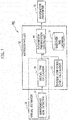
- the information presenting apparatus 100 shown in Fig. 1 includes a surrounding risk detector 11, a microcontroller 12, and an information presenter 15.
- the surrounding risk detector 11 detects a surrounding risk, which is a factor existing in the surroundings of the vehicle to hinder the autonomous driving control. Specifically, the surrounding risk detector 11 detects a map position at which it is predicted that the autonomous driving control may be prevented from proceeding, or an obstacle which serves as a cause for preventing the autonomous driving control from proceeding. For example, using a camera mounted in the vehicle, sensor information from a laser radar or an infrared sensor, or GPS information, the surrounding risk detector 11 detects a surrounding risk which is another vehicle parked on a current lane of travel of the vehicle, a crowded section, or a pedestrian entering or likely to enter the current lane of travel of the vehicle.
- the information presenter 15 presents information on allowableness of an action other than driving to the driver.
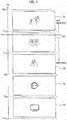
- the information presenter 15 is a display (21a, 21b) provided in a dashboard 32 and configured to display an icon image or icon images shown in Fig. 3 to be described later, as information on allowableness of an action other than driving.
- the information presenter 15 may display the information indicating an action other than driving on part of a front windshield 33 or a rearview mirror 34.
- the microcontroller 12 includes a CPU, a memory, and an input and output unit.
- the CPU executes preinstalled computer programs to implement multiple information processors in the information presenting apparatus 100.
- the information processors implemented by the microcontroller 12 include an arrival time calculator 18, a system confidence level calculator 13, and an information presentation controller 14. Part of the memory in the microcontroller 12 constitutes a takeover time database 17 (a data storage).
- the microcontroller 12 may be used also as an ECU used for other vehicle control (e.g., the autonomous driving control).
- the arrival time calculator 18 calculates an arrival time TR which is a period of time required for the vehicle to arrive at a surrounding risk detected by the surrounding risk detector 11.
- the arrival time TR is time expected to be required for the vehicle at its current position to arrive at a surrounding risk.
- the arrival time calculator 18 receives input of information on a surrounding risk and information on the current position of the vehicle, and computes the arrival time TR based on these pieces of information.
- the information on a surrounding risk is inputted by the surrounding risk detector 11, and the information on the current position of the vehicle is inputted by a navigation system installed in the vehicle.
- the surrounding risk detector 11 and the arrival time calculator 18 constitute an arrival estimator 16 configured to estimate the arrival time required for the vehicle to arrive at a surrounding risk.
- the arrival time calculator 18 computes the arrival time TR using Formula (1).
- OBD represents the distance from the vehicle to an obstacle (such as another vehicle or a pedestrian)
- LDD represents the distance to a point where the vehicle deviates from a roadway
- VLD represents the distance to a terminal point of an expressway
- VL represents the speed of the vehicle
- TTC represents a time to collision with a preceding vehicle.
- L1, L2, and L3 are coefficients that vary depending on the travelling conditions of the vehicle (the speed of the vehicle and the coefficient of road surface friction) and the type of the vehicle.
- the terminal point of an expressway is, when driving control is to be switched to the manual driving mode at a tollbooth of a highway, the position of the tollbooth or a position short of the tollbooth by a predetermined distance.
- the system confidence level calculator 13 calculates a system confidence level based on at least one of sensor detection rate, CPU load, and fidelity of a path to a computed result of a target value.
- the system confidence level indicates the status of the control system used for the autonomous driving control.
- the sensor detection rate is a ratio of the current capability of a sensor to the maximum capability of the sensor.
- the sensor is a sensor used for the autonomous driving control to measure targets inside and outside the vehicle. For example, for a sensor capable of detecting an obstacle up to 200 meters ahead of the vehicle, the sensor detection rate is 0.5 if the laser sensor can detect only an obstacle 100 meters ahead.
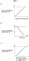
- the system confidence level calculator 13 calculates a system confidence coefficient Sa based on the sensor detection rate by referring to data shown in Fig. 2(a) .
- the CPU load is a ratio of the current arithmetic processing capability of a CPU to the maximum arithmetic processing capability of the CPU.
- the CPU is a central processing unit used for the autonomous driving control.
- the system confidence level calculator 13 calculates a system confidence coefficient Sb based on the CPU load by referring to data shown in Fig. 2(b) .
- the fidelity of a path to a computed result of a target value indicates how well a travel path taken by the vehicle under the autonomous driving control coincides with a road (target value) indicated by the navigation system. For example, the fidelity is low when a travel path deviates greatly from a target value due to darkness of nighttime or bad weather (such as rain or strong wind). The fidelity is high when a travel path does not deviate so much from a target value in daytime.
- the system confidence level calculator 13 calculates a system confidence coefficient Sc based on the fidelity of a path to a computed result of a target value by referring to data shown in Fig. 2(c) .
- Each of the system confidence coefficients (Sa, Sb, Sc) is variable from a predetermined positive number (lower-limit value) to 1.
- the data shown in Figs. 2(a) to 2(c) are stored in a memory accessible to the system confidence level calculator 13.
- the system confidence coefficients (Sa, Sc) increase as the sensor detection rate and the fidelity of a path to a computed result of a target value increase, respectively, and the system confidence coefficient (Sb) decreases as the CPU load increases.
- the system confidence level calculator 13 calculates a system confidence level (S) by multiplying the system confidence coefficients (Sa, Sb, Sc) as shown in Formula (2).
- S Sa ⁇ Sb ⁇ Sc ⁇ 100 %
- the takeover time database 17 stores, for each action other than driving, takeover time TT required for the driver performing the action other than driving to be ready to take over and drive the vehicle. Specifically, the takeover time database 17 stores the takeover time TT for each of multiple predefined types (A1 to A5).
- the takeover time TT is time required between when a driver notices that they should stop an action other than driving and when the driver stops the action other than driving and becomes ready to drive the vehicle by themselves. For example, it takes about one second or so for a driver whose hands are off the steering wheel to grip the steering wheel. It takes about one second or so for a driver whose eyes are fixed on a portable device or the like to turn their eyes to the front of the vehicle.
- the takeover time database 17 stores the takeover time for each action other than driving from a physical point of view.
- the type A1 in Fig. 3 includes an action that uses sight and hearing but not the other senses: a hand (touch), smell, and taste. An example of such an action is watching television installed in the vehicle compartment.
- the type A1 has the shortest takeover time among all the types (A1 to A5) because an action of the type A1 does not involve a hand or speaking.
- the type A2 includes an action of conversing with another person using a hands-free headset, such as taking on the phone, and an action of using a head-up display such as a wearable device.
- the type A2 has the shortest takeover time (TTa) next to the type A1 because an action of the type A2 does not involve a hand (touch) but involves speaking.
- the type A3 includes an action of operating a communication device using sight and a hand (touch), e.g., Internet browsing, texting, and gaming.
- the type A3 has the shortest takeover time (TTb) next to the type A2 because an action of the type A3 involves a hand.
- TTb takeover time
- the type A4 includes an action of reading a book held in the hand.
- the type A4 has the shortest takeover time (TTc) next to the type A3 because reading a book requires a higher concentration than actions of the other types (A1 to A3, A5).
- the type A5 includes an action involving a hand (touch), taste, and smell, i.e., eating.
- the type A5 has the longest takeover time (TTd) among all the types (A1 to A5) because the driver has to put the food and plate stably inside the vehicle to transition from eating to driving.
- the takeover time for the type A1 is equal to the lower limit (TR LL ) of the arrival time.
- the upper limit of the arrival time TR is set to be even longer than the takeover time (TTd).
- the relations between the types (A1 to A5) and the takeover time TT described hereinabove are merely examples.
- the types may be set based on criteria other than the human senses, or the types (A1 to A5) in Fig. 3 may be used as they are but arranged in a different order of the takeover time TT.
- the information presentation controller 14 controls switching of the content of the information presented on the information presenter 15 according to the arrival time TR estimated by the arrival estimator 16 and the system confidence level S calculated by the system confidence level calculator 13.
- the information presentation controller 14 selects an action (or actions) that the driver is allowed to perform other than driving according to the arrival time TR, and presents the action to the driver. For example, the information presentation controller 14 determines an action that the driver is allowed to perform other than driving by comparing the arrival time TR calculated by the arrival time calculator 18 with the takeover time TT stored in the takeover time database 17.
- the information presentation controller 14 presents, on the information presenter 15, information indicating an action other than driving the takeover time TT for which is equal to or shorter than the arrival time TR. For example, when the arrival time TR is anywhere between the takeover time TTc and the takeover time TTd as shown in Fig. 4 , an action other than driving the takeover time TT for which is equal to or smaller than the arrival time TR is the actions belonging to the types A1 to A4.
- the information presentation controller 14 presents, on the information presenter 15, icon images for the types A1 to A4 shown in Fig. 4 . For example, as shown in Fig.
- multiple icon images may be displayed together on the display (21a, 21b), the front windshield 33, or the rearview mirror 34 in Fig. 6 .
- the driver can understand the condition of the system used for the autonomous driving control.
- FIG. 7 an example of an information presenting method using the information presenting apparatus 100 in Fig. 1 is described.
- the flowchart in Fig. 7 is repeated with a period predetermined by the microcontroller.
- Step S01 the system confidence level calculator 13 calculates the system confidence level S based on the sensor detection rate, the CPU load, and the fidelity of a path to a computed result of a target value, using Formula (2).
- Step S03 the information presentation controller 14 determines whether the system confidence level S is larger than the predetermined threshold (Slimit).
- Step S05 the arrival time calculator 18 calculates the arrival time TR required for the vehicle to arrive at a surrounding risk detected by the surrounding risk detector 11.
- Step S07 the information presentation controller 14 displays, on the information presenter 15, an icon image indicating an action of the type (A1 to A5) the takeover time TT for which is equal to or shorter than the arrival time TR.
- the information presentation controller 14 determines that there is no surrounding risk, and sets the arrival time to its upper limit (TR LL ). As a result, the information presenter 15 displays icon images for all the types (A1 to A5).
- Step S09 the information presentation controller 14 sets the arrival time TR to its lower limit (TR LL ), Since no type (A1 to A5) has the takeover time TT that is equal to or shorter than the arrival time (TR LL ), the information presenter 15 does not display any icon image indicating an action that the driver is allowed to perform other than driving (S11). Thereby, the driver can be informed that there is no action that the driver is allowed to perform other than driving.
- Slimit the predetermined threshold
- the first embodiment described above can achieve the following advantageous effects.
- the information presentation controller 14 controls switching of the content of the information presented on the information presenter 15 according to the system confidence level S calculated by the system confidence level calculator 13.
- the presentation of an action that the driver may perform other than driving enables the driver to understand the condition of the system used for the autonomous driving control. This decreases the burden on the driver to monitor autonomous driving, and raises the driver's feeling of reassurance and reliability with the autonomous driving control.
- the information presentation controller 14 presents, on the information presenter 15, information indicating an action that the driver is allowed to perform other than driving.
- the presentation of the action that the driver is allowed to perform other than driving enables the driver to understand the condition of the system used for the autonomous driving control.
- the system confidence level calculator 13 calculates the system confidence level S based on at least one of the detection rate of the sensor used for the autonomous driving control, the load rate of the central processing unit used for the autonomous driving control, and the fidelity of a path to a computed result of a target value. Thereby, the condition of the control system used for the autonomous driving control can be accurately determined.
- the information presentation controller 14 determines information to present to the driver by comparing the arrival time TR estimated by the arrival estimator 16 with the takeover time TT stored in the takeover time database 17.
- the driver performing the presented action other than driving can take over and drive the vehicle before a transition is made from the autonomous driving control to the manual driving control.
- the driver's feeling of reassurance and reliability with the autonomous driving control is raised.
- the information presentation controller 14 presents, on the information presenter 15, information indicating an action other than driving the takeover time TT for which is equal to or shorter than the arrival time TR.
- the driver performing the action other than driving the takeover time TT for which is equal to or shorter than the arrival time TR can take over and drive the vehicle before a transition is made from the autonomous driving control to the manual driving control.
- the information presenting apparatus 100 in Fig. 1 may present an action that the driver is not allowed to perform other than driving, based on the arrival time TR and the system confidence level S.
- the information presentation controller 14 presents, on the information presenter 15, information indicating an action that the driver is not allowed to perform other than driving, as the information on allowableness of an action other than driving. Specifically, as the information indicating an action that the driver is not allowed to perform other than driving, the information presentation controller 14 presents, on the information presenter 15, information indicating an action other than driving the takeover time TT for which is longer than the arrival time TR.
- an icon image displayed on the information presenter 15 is a prohibition symbol superimposed on the icon shown in Fig. 3 . More specifically, an icon indicating an action that the driver is not allowed to perform other than driving is formed by superimposition of a prohibition symbol on an icon indicating an action other than driving.
- the takeover time TT for each of the actions other than driving stored in the takeover time database 17 may be the same as that shown in Fig. 3 .
- Actions other than driving that belong to types (B1 to B5) may be the same as those belonging to the types (A1 to A5) in Fig. 3 .
- the information presentation controller 14 When the system confidence level S is smaller than the predetermined threshold (Slimit), a transition is likely to be made from the autonomous driving control to the manual driving control. Thus, to notify the driver of the probable transition to manual driving, the information presentation controller 14 presents, to the driver, information indicating that the driver is not allowed to perform actions other than driving that belong to all the types (B1 to B5). When the system confidence level S is equal to or larger than the predetermined threshold (Slimit), on the other hand, a transition is not likely to be made from the autonomous driving control to the manual driving control. Thus, the information presentation controller 14 selects an action that the driver is not allowed to perform other than driving according to the arrival time TR, and presents the action to the driver. For example, the information presentation controller 14 determines an action that the driver is not allowed to perform other than driving by comparing the arrival time TR calculated by the arrival time calculator 18 with the takeover time TT stored in the takeover time database 17.
- the information presentation controller 14 presents, on the information presenter 15, information indicating an action other than driving the takeover time TT for which is longer than the arrival time TR. For example, when the arrival time TR is anywhere between the takeover time TTc and the takeover time TTd as shown in Fig. 9 , an action other than driving the takeover time TT for which is longer than the arrival time TR is the action belonging to the type B5.
- the information presentation controller 14 presents, on the information presenter 15, an icon image for the type B5 shown in Fig. 9 . For example, as shown in Fig.
- the icon image for the type B5 may be displayed on the display (21a, 21b), the front windshield 33, or the rearview mirror 34 in Fig. 6 .
- the driver can easily understand the condition of the system used for the autonomous driving control.
- Step S07 the information presentation controller 14 displays, on the information presenter 15, an icon image for the type (B1 to B5) the takeover time TT for which is longer than the arrival time TR.
- the surrounding risk detector 11 detects no surrounding risk
- the information presentation controller 14 determines that there is no surrounding risk, and sets the arrival time to its upper limit (TR LL ).
- the information presenter 15 does not display any icon image indicating an action that the driver is not allowed to perform other than driving.
- Step S09 the information presentation controller 14 sets the arrival time TR to its lower limit (TR LL ).
- the information presenter 15 displays icon images for all the types (B1 to B5). Thereby, the driver can be informed that none of the actions other than driving is allowed (S19).
- the information presentation controller 14 presents, on the information presenter 15, information indicating an action that the driver is not allowed to perform other than driving.
- the presentation of the action that the driver is not allowed to perform other than driving enables the driver to understand the condition of the system used for the autonomous driving control.
- the information presentation controller 14 presents, on the information presenter 15, information indicating an action other than driving the takeover time TT for which is longer than the arrival time TR. If an action other than driving that the driver is performing is not presented on the information presenter 15, the driver can take over and drive the vehicle before switch is made from the autonomous driving control to the manual driving control.
- the information presentation controller 14 can present, on the information presenter 15, both of information indicating an action that the driver is allowed to perform other than driving and information indicating an action that the driver is not allowed to perform other than driving.
- the takeover time database 17 stores icon images indicating actions belonging to the types (A1 to A5) shown in Fig. 3 as well as icon images indicating actions belonging to the types (B1 to B5) shown in Fig. 8 .
- the information presentation controller 14 may display, as an action that the driver is allowed to perform other than driving, an icon image indicating an action other than driving belonging to any of the types (A1 to A5) the takeover time TT for which is equal to or shorter than the arrival time TR, and display, as an action that the driver is not allowed to perform other than driving, an icon image indicating an action other than driving belonging to any of the types (B1 to B5) the take over time TT for which is longer than the arrival time TR.
Abstract
Description
- The present invention relates to an information presenting apparatus and an information presenting method.
- An apparatus and method for preventing a driver from falling asleep by changing alarm sounding timing according to the state of the driver is conventionally known (see Patent Literature 1). When the eyes of a driver are closed for a period equal to or longer than a first threshold,
Patent Literature 1 sounds the alarm for detection of a collision danger earlier than in a normal mode. - Patent Literature 1:
Japanese Patent Application Publication No. 2008-181327 -
Patent Literature 1 is a technique pertaining to prevention of a driver's falling asleep, and is not configured to sound the alarm according to an action other than driving that the driver may perform during autonomous driving control in which a vehicle is driven autonomously. - The present invention has been made in consideration of the above problem, and aims to provide an information presenting apparatus and an information presenting method which can raise a driver's feeling of reassurance and reliability with the autonomous driving control.
- An information presenting apparatus according to an aspect of the present invention comprises a system confidence level calculator configured to calculate a system confidence level of autonomous driving control, an information presenter configured to present, to a driver, information on allowableness of an action other than driving, and an information presentation controller configured to control switching of a content of the information presented on the information presenter, according to the system confidence level calculated by the system confidence level calculator.
-
- [
Fig. 1] Fig. 1 is a block diagram showing the configuration of aninformation presenting apparatus 100 according to an embodiment. - [
Fig. 2] Fig. 2(a) is a graph showing an example of the relation between sensor detection rate and a system confidence coefficient Sa,Fig. 2(b) is a graph showing an example of the relation between CPU load and a system confidence coefficient Sb, and -
Fig. 2(c) is a graph showing an example of the relation between the fidelity of a path to a computed result of a target value and a system confidence coefficient Sc. - [
Fig. 3] Fig. 3 shows an example of takeover time TT for each action other than driving, which is stored in atakeover time database 17 inFig. 1 , and shows actions that a driver is allowed to perform other than driving. - [
Fig. 4] Fig. 4 is a diagram illustrating operation of aninformation presentation controller 14 that selects, according to an arrival time TR, a type of an action that the driver is allowed to perform other than driving, and presents the type to the driver. - [
Fig. 5] Fig. 5 is a diagram showing a display example of an action that the driver is allowed to perform other than driving, the action being selected according to the arrival time TR shown inFig. 4 , andFig. 5(b) is a diagram showing a display example of an action that the driver is not allowed to perform other than driving, the action being selected according to the arrival time TR shown inFig. 9 . - [
Fig. 6] Fig. 6 is an external view showing an example of aninformation presenter 15 installed in a vehicle compartment. - [
Fig. 7] Fig. 7 is a flowchart showing an example of an information presenting method using theinformation presenting apparatus 100 inFig. 1 . - [
Fig. 8] Fig. 8 shows an example of the takeover time TT for each action other than driving in a second embodiment, and shows actions that the driver is not allowed to perform other than driving. - [
Fig. 9] Fig. 9 is a diagram illustrating operation of theinformation presentation controller 14 that selects, according to the arrival time TR, a type of an action that the driver is not allowed to perform other than driving, and presents the type to the driver. - [
Fig. 10] Fig. 10 is a flowchart showing an example of an information presenting method according to the second embodiment. - Embodiments of the present invention are described hereinbelow with reference to the drawings. The same components are denoted by the same reference signs to avoid repetitive description.
- With reference to
Fig. 1 , the configuration of aninformation presenting apparatus 100 according to a first embodiment is described. Theinformation presenting apparatus 100 is applicable to an autonomous vehicle capable of switching between autonomous driving control, in which a vehicle is driven autonomously, and manual driving control, in which the vehicle is driven by a driver, the switching being made based on travelling conditions of the vehicle and outside circumstances of the vehicle. Theinformation presenting apparatus 100 presents, to the driver, information on allowableness of an action other than driving during the autonomous driving control. - The
information presenting apparatus 100 of the first embodiment presents, to the driver, information indicating an action that the driver is allowed to perform other than driving during the autonomous driving control. Multiple types are predefined for the actions other than driving. Theinformation presenting apparatus 100 displays only a type that the driver is allowed to perform, which is determined according to a control system used for the autonomous driving control and surrounding environments of the vehicle. - For example, when switch from the autonomous driving control to the manual driving control is unnecessary, the
information presenting apparatus 100 presents all the types to the driver as the actions that the driver is allowed to perform other than driving. When switch from the autonomous driving control to the manual driving control is necessary, on the other hand, theinformation presenting apparatus 100 displays only a type that the driver is allowed to perform, which is determined according to the urgency of the need for the switch. - Specifically, the
information presenting apparatus 100 shown inFig. 1 includes a surroundingrisk detector 11, amicrocontroller 12, and aninformation presenter 15. - The surrounding
risk detector 11 detects a surrounding risk, which is a factor existing in the surroundings of the vehicle to hinder the autonomous driving control. Specifically, the surroundingrisk detector 11 detects a map position at which it is predicted that the autonomous driving control may be prevented from proceeding, or an obstacle which serves as a cause for preventing the autonomous driving control from proceeding. For example, using a camera mounted in the vehicle, sensor information from a laser radar or an infrared sensor, or GPS information, the surroundingrisk detector 11 detects a surrounding risk which is another vehicle parked on a current lane of travel of the vehicle, a crowded section, or a pedestrian entering or likely to enter the current lane of travel of the vehicle. - The
information presenter 15 presents information on allowableness of an action other than driving to the driver. Specifically, as shown inFig. 6 , theinformation presenter 15 is a display (21a, 21b) provided in adashboard 32 and configured to display an icon image or icon images shown inFig. 3 to be described later, as information on allowableness of an action other than driving. Needless to say, theinformation presenter 15 may display the information indicating an action other than driving on part of afront windshield 33 or arearview mirror 34. - The
microcontroller 12 includes a CPU, a memory, and an input and output unit. The CPU executes preinstalled computer programs to implement multiple information processors in theinformation presenting apparatus 100. The information processors implemented by themicrocontroller 12 include anarrival time calculator 18, a systemconfidence level calculator 13, and aninformation presentation controller 14. Part of the memory in themicrocontroller 12 constitutes a takeover time database 17 (a data storage). Themicrocontroller 12 may be used also as an ECU used for other vehicle control (e.g., the autonomous driving control). - The
arrival time calculator 18 calculates an arrival time TR which is a period of time required for the vehicle to arrive at a surrounding risk detected by the surroundingrisk detector 11. The arrival time TR is time expected to be required for the vehicle at its current position to arrive at a surrounding risk. Thus, thearrival time calculator 18 receives input of information on a surrounding risk and information on the current position of the vehicle, and computes the arrival time TR based on these pieces of information. The information on a surrounding risk is inputted by the surroundingrisk detector 11, and the information on the current position of the vehicle is inputted by a navigation system installed in the vehicle. The surroundingrisk detector 11 and thearrival time calculator 18 constitute anarrival estimator 16 configured to estimate the arrival time required for the vehicle to arrive at a surrounding risk. - For example, the
arrival time calculator 18 computes the arrival time TR using Formula (1). In Formula (1), OBD represents the distance from the vehicle to an obstacle (such as another vehicle or a pedestrian), LDD represents the distance to a point where the vehicle deviates from a roadway, VLD represents the distance to a terminal point of an expressway, VL represents the speed of the vehicle, and TTC represents a time to collision with a preceding vehicle. L1, L2, and L3 are coefficients that vary depending on the travelling conditions of the vehicle (the speed of the vehicle and the coefficient of road surface friction) and the type of the vehicle. The terminal point of an expressway is, when driving control is to be switched to the manual driving mode at a tollbooth of a highway, the position of the tollbooth or a position short of the tollbooth by a predetermined distance. In addition, "Min" indicates the smallest one of the values inside the following parentheses.
[Expression 1]
- The system
confidence level calculator 13 calculates a system confidence level based on at least one of sensor detection rate, CPU load, and fidelity of a path to a computed result of a target value. The system confidence level indicates the status of the control system used for the autonomous driving control. - The sensor detection rate is a ratio of the current capability of a sensor to the maximum capability of the sensor. The sensor is a sensor used for the autonomous driving control to measure targets inside and outside the vehicle. For example, for a sensor capable of detecting an obstacle up to 200 meters ahead of the vehicle, the sensor detection rate is 0.5 if the laser sensor can detect only an
obstacle 100 meters ahead. The systemconfidence level calculator 13 calculates a system confidence coefficient Sa based on the sensor detection rate by referring to data shown inFig. 2(a) . - The CPU load is a ratio of the current arithmetic processing capability of a CPU to the maximum arithmetic processing capability of the CPU. The CPU is a central processing unit used for the autonomous driving control. The system
confidence level calculator 13 calculates a system confidence coefficient Sb based on the CPU load by referring to data shown inFig. 2(b) . - The fidelity of a path to a computed result of a target value indicates how well a travel path taken by the vehicle under the autonomous driving control coincides with a road (target value) indicated by the navigation system. For example, the fidelity is low when a travel path deviates greatly from a target value due to darkness of nighttime or bad weather (such as rain or strong wind). The fidelity is high when a travel path does not deviate so much from a target value in daytime. The system
confidence level calculator 13 calculates a system confidence coefficient Sc based on the fidelity of a path to a computed result of a target value by referring to data shown inFig. 2(c) . - Each of the system confidence coefficients (Sa, Sb, Sc) is variable from a predetermined positive number (lower-limit value) to 1. The data shown in
Figs. 2(a) to 2(c) are stored in a memory accessible to the systemconfidence level calculator 13. The system confidence coefficients (Sa, Sc) increase as the sensor detection rate and the fidelity of a path to a computed result of a target value increase, respectively, and the system confidence coefficient (Sb) decreases as the CPU load increases. - The system
confidence level calculator 13 calculates a system confidence level (S) by multiplying the system confidence coefficients (Sa, Sb, Sc) as shown in Formula (2).
- The
takeover time database 17 stores, for each action other than driving, takeover time TT required for the driver performing the action other than driving to be ready to take over and drive the vehicle. Specifically, thetakeover time database 17 stores the takeover time TT for each of multiple predefined types (A1 to A5). - The takeover time TT is time required between when a driver notices that they should stop an action other than driving and when the driver stops the action other than driving and becomes ready to drive the vehicle by themselves. For example, it takes about one second or so for a driver whose hands are off the steering wheel to grip the steering wheel. It takes about one second or so for a driver whose eyes are fixed on a portable device or the like to turn their eyes to the front of the vehicle. The
takeover time database 17 stores the takeover time for each action other than driving from a physical point of view. - The type A1 in
Fig. 3 includes an action that uses sight and hearing but not the other senses: a hand (touch), smell, and taste. An example of such an action is watching television installed in the vehicle compartment. The type A1 has the shortest takeover time among all the types (A1 to A5) because an action of the type A1 does not involve a hand or speaking. The type A2 includes an action of conversing with another person using a hands-free headset, such as taking on the phone, and an action of using a head-up display such as a wearable device. The type A2 has the shortest takeover time (TTa) next to the type A1 because an action of the type A2 does not involve a hand (touch) but involves speaking. The type A3 includes an action of operating a communication device using sight and a hand (touch), e.g., Internet browsing, texting, and gaming. The type A3 has the shortest takeover time (TTb) next to the type A2 because an action of the type A3 involves a hand. - The type A4 includes an action of reading a book held in the hand. The type A4 has the shortest takeover time (TTc) next to the type A3 because reading a book requires a higher concentration than actions of the other types (A1 to A3, A5). The type A5 includes an action involving a hand (touch), taste, and smell, i.e., eating. The type A5 has the longest takeover time (TTd) among all the types (A1 to A5) because the driver has to put the food and plate stably inside the vehicle to transition from eating to driving. Note that the takeover time for the type A1 is equal to the lower limit (TRLL) of the arrival time. The upper limit of the arrival time TR is set to be even longer than the takeover time (TTd). The relations between the types (A1 to A5) and the takeover time TT described hereinabove are merely examples. The types may be set based on criteria other than the human senses, or the types (A1 to A5) in
Fig. 3 may be used as they are but arranged in a different order of the takeover time TT. - The
information presentation controller 14 controls switching of the content of the information presented on theinformation presenter 15 according to the arrival time TR estimated by thearrival estimator 16 and the system confidence level S calculated by the systemconfidence level calculator 13. - Specifically, when the system confidence level S is smaller than a predetermined threshold (Slimit), a transition is likely to be made from the autonomous driving control to the manual driving control. Thus, to notify the driver of the probable transition to manual driving, the
information presentation controller 14 presents, to the driver, information indicating that there is no action that the driver is allowed to perform other than driving. On the other hand, when the system confidence level S is equal to or larger than the predetermined threshold (Slimit), a transition is not likely to be made from the autonomous driving control to the manual driving control. Thus, theinformation presentation controller 14 selects an action (or actions) that the driver is allowed to perform other than driving according to the arrival time TR, and presents the action to the driver. For example, theinformation presentation controller 14 determines an action that the driver is allowed to perform other than driving by comparing the arrival time TR calculated by thearrival time calculator 18 with the takeover time TT stored in thetakeover time database 17. - As the information indicating an action that the driver is allowed to perform other than driving, the
information presentation controller 14 presents, on theinformation presenter 15, information indicating an action other than driving the takeover time TT for which is equal to or shorter than the arrival time TR. For example, when the arrival time TR is anywhere between the takeover time TTc and the takeover time TTd as shown inFig. 4 , an action other than driving the takeover time TT for which is equal to or smaller than the arrival time TR is the actions belonging to the types A1 to A4. Thus, as the information indicating an action that the driver is allowed to perform other than driving, theinformation presentation controller 14 presents, on theinformation presenter 15, icon images for the types A1 to A4 shown inFig. 4 . For example, as shown inFig. 5(a) , multiple icon images may be displayed together on the display (21a, 21b), thefront windshield 33, or therearview mirror 34 inFig. 6 . By looking at the icon images indicating actions that the driver is allowed to perform, the driver can understand the condition of the system used for the autonomous driving control. - Next, with reference to
Fig. 7 , an example of an information presenting method using theinformation presenting apparatus 100 inFig. 1 is described. The flowchart inFig. 7 is repeated with a period predetermined by the microcontroller. - In Step S01, the system
confidence level calculator 13 calculates the system confidence level S based on the sensor detection rate, the CPU load, and the fidelity of a path to a computed result of a target value, using Formula (2). In Step S03, theinformation presentation controller 14 determines whether the system confidence level S is larger than the predetermined threshold (Slimit). - When the system confidence level S is larger than the predetermined threshold (Slimit) (YES in S03), indicating that the system has no matter of urgency in its condition, it is determined that a transition is not likely to be made from the autonomous driving control to the manual driving control. Then, in Step S05, the
arrival time calculator 18 calculates the arrival time TR required for the vehicle to arrive at a surrounding risk detected by the surroundingrisk detector 11. Then, in Step S07, theinformation presentation controller 14 displays, on theinformation presenter 15, an icon image indicating an action of the type (A1 to A5) the takeover time TT for which is equal to or shorter than the arrival time TR. When the surroundingrisk detector 11 detects no surrounding risk, theinformation presentation controller 14 determines that there is no surrounding risk, and sets the arrival time to its upper limit (TRLL). As a result, theinformation presenter 15 displays icon images for all the types (A1 to A5). - Meanwhile, when the system confidence level S is equal to or smaller than the predetermined threshold (Slimit) (NO in S03), indicating that the system has a matter of urgency in its condition, it is determined that a transition is likely to be made from the autonomous driving control to the manual driving control. Then, in Step S09, the
information presentation controller 14 sets the arrival time TR to its lower limit (TRLL), Since no type (A1 to A5) has the takeover time TT that is equal to or shorter than the arrival time (TRLL), theinformation presenter 15 does not display any icon image indicating an action that the driver is allowed to perform other than driving (S11). Thereby, the driver can be informed that there is no action that the driver is allowed to perform other than driving. - The first embodiment described above can achieve the following advantageous effects.
- The
information presentation controller 14 controls switching of the content of the information presented on theinformation presenter 15 according to the system confidence level S calculated by the systemconfidence level calculator 13. The presentation of an action that the driver may perform other than driving enables the driver to understand the condition of the system used for the autonomous driving control. This decreases the burden on the driver to monitor autonomous driving, and raises the driver's feeling of reassurance and reliability with the autonomous driving control. - As the information on allowableness of an action other than driving, the
information presentation controller 14 presents, on theinformation presenter 15, information indicating an action that the driver is allowed to perform other than driving. The presentation of the action that the driver is allowed to perform other than driving enables the driver to understand the condition of the system used for the autonomous driving control. - The system
confidence level calculator 13 calculates the system confidence level S based on at least one of the detection rate of the sensor used for the autonomous driving control, the load rate of the central processing unit used for the autonomous driving control, and the fidelity of a path to a computed result of a target value. Thereby, the condition of the control system used for the autonomous driving control can be accurately determined. - The
information presentation controller 14 determines information to present to the driver by comparing the arrival time TR estimated by thearrival estimator 16 with the takeover time TT stored in thetakeover time database 17. The driver performing the presented action other than driving can take over and drive the vehicle before a transition is made from the autonomous driving control to the manual driving control. Thus, the driver's feeling of reassurance and reliability with the autonomous driving control is raised. - As the information indicating an action that the driver is allowed to perform other than driving, the
information presentation controller 14 presents, on theinformation presenter 15, information indicating an action other than driving the takeover time TT for which is equal to or shorter than the arrival time TR. The driver performing the action other than driving the takeover time TT for which is equal to or shorter than the arrival time TR can take over and drive the vehicle before a transition is made from the autonomous driving control to the manual driving control. - Instead of presenting an action that the driver is allowed to perform other than driving, the
information presenting apparatus 100 inFig. 1 may present an action that the driver is not allowed to perform other than driving, based on the arrival time TR and the system confidence level S. - In a second embodiment, the
information presentation controller 14 presents, on theinformation presenter 15, information indicating an action that the driver is not allowed to perform other than driving, as the information on allowableness of an action other than driving. Specifically, as the information indicating an action that the driver is not allowed to perform other than driving, theinformation presentation controller 14 presents, on theinformation presenter 15, information indicating an action other than driving the takeover time TT for which is longer than the arrival time TR. - As shown in
Fig. 8 , an icon image displayed on theinformation presenter 15 is a prohibition symbol superimposed on the icon shown inFig. 3 . More specifically, an icon indicating an action that the driver is not allowed to perform other than driving is formed by superimposition of a prohibition symbol on an icon indicating an action other than driving. However, the takeover time TT for each of the actions other than driving stored in thetakeover time database 17 may be the same as that shown inFig. 3 . Actions other than driving that belong to types (B1 to B5) may be the same as those belonging to the types (A1 to A5) inFig. 3 . - When the system confidence level S is smaller than the predetermined threshold (Slimit), a transition is likely to be made from the autonomous driving control to the manual driving control. Thus, to notify the driver of the probable transition to manual driving, the
information presentation controller 14 presents, to the driver, information indicating that the driver is not allowed to perform actions other than driving that belong to all the types (B1 to B5). When the system confidence level S is equal to or larger than the predetermined threshold (Slimit), on the other hand, a transition is not likely to be made from the autonomous driving control to the manual driving control. Thus, theinformation presentation controller 14 selects an action that the driver is not allowed to perform other than driving according to the arrival time TR, and presents the action to the driver. For example, theinformation presentation controller 14 determines an action that the driver is not allowed to perform other than driving by comparing the arrival time TR calculated by thearrival time calculator 18 with the takeover time TT stored in thetakeover time database 17. - As the information indicating an action that the driver is not allowed to perform other than driving, the
information presentation controller 14 presents, on theinformation presenter 15, information indicating an action other than driving the takeover time TT for which is longer than the arrival time TR. For example, when the arrival time TR is anywhere between the takeover time TTc and the takeover time TTd as shown inFig. 9 , an action other than driving the takeover time TT for which is longer than the arrival time TR is the action belonging to the type B5. Thus, as the information indicating an action that the driver is not allowed to perform other than driving, theinformation presentation controller 14 presents, on theinformation presenter 15, an icon image for the type B5 shown inFig. 9 . For example, as shown inFig. 5(b) , the icon image for the type B5 may be displayed on the display (21a, 21b), thefront windshield 33, or therearview mirror 34 inFig. 6 . By looking at the icon image indicating an action that the driver is not allowed to perform, the driver can easily understand the condition of the system used for the autonomous driving control. - With reference to
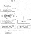
Fig. 10 , operation of theinformation presenting apparatus 100 according to the second embodiment is described. When the system confidence level S is larger than the predetermined threshold (Slimit) (YES in S03), in Step S07 theinformation presentation controller 14 displays, on theinformation presenter 15, an icon image for the type (B1 to B5) the takeover time TT for which is longer than the arrival time TR. When the surroundingrisk detector 11 detects no surrounding risk, theinformation presentation controller 14 determines that there is no surrounding risk, and sets the arrival time to its upper limit (TRLL). As a result, theinformation presenter 15 does not display any icon image indicating an action that the driver is not allowed to perform other than driving. - Meanwhile, when the system confidence level S is equal to or smaller than the predetermined threshold (Slimit) (NO in S03), in Step S09 the
information presentation controller 14 sets the arrival time TR to its lower limit (TRLL). As a result, theinformation presenter 15 displays icon images for all the types (B1 to B5). Thereby, the driver can be informed that none of the actions other than driving is allowed (S19). - Other configurations and operations of the
information presenting apparatus 100 are the same as those of the first embodiment, and are therefore not described. - As the information on allowableness of an action other than driving, the
information presentation controller 14 presents, on theinformation presenter 15, information indicating an action that the driver is not allowed to perform other than driving. The presentation of the action that the driver is not allowed to perform other than driving enables the driver to understand the condition of the system used for the autonomous driving control. - As the information indicating an action that the driver is not allowed to perform other than driving, the
information presentation controller 14 presents, on theinformation presenter 15, information indicating an action other than driving the takeover time TT for which is longer than the arrival time TR. If an action other than driving that the driver is performing is not presented on theinformation presenter 15, the driver can take over and drive the vehicle before switch is made from the autonomous driving control to the manual driving control. - Although the present invention has been described hereinabove using the embodiments, the present invention is not limited to what is described in those embodiments, and can be modified and improved variously, as is apparent to those skilled in the art.
- For example, the
information presentation controller 14 can present, on theinformation presenter 15, both of information indicating an action that the driver is allowed to perform other than driving and information indicating an action that the driver is not allowed to perform other than driving. In this case, thetakeover time database 17 stores icon images indicating actions belonging to the types (A1 to A5) shown inFig. 3 as well as icon images indicating actions belonging to the types (B1 to B5) shown inFig. 8 . Theinformation presentation controller 14 may display, as an action that the driver is allowed to perform other than driving, an icon image indicating an action other than driving belonging to any of the types (A1 to A5) the takeover time TT for which is equal to or shorter than the arrival time TR, and display, as an action that the driver is not allowed to perform other than driving, an icon image indicating an action other than driving belonging to any of the types (B1 to B5) the take over time TT for which is longer than the arrival time TR. -
- 13
- system confidence level calculator
- 14
- information presentation controller
- 15
- information presenter
- 16
- arrival estimator
- 17
- takeover time database (data storage unit)
Claims (8)
- An information presenting apparatus for use in an autonomous vehicle capable of switching, based on a travelling condition of the vehicle and an outside circumstance of the vehicle, between autonomous driving control, in which the vehicle is driven autonomously, and manual driving control, in which the vehicle is driven by a driver, the information presenting apparatus comprising:a system confidence level calculator configured to calculate a system confidence level of the autonomous driving control;an information presenter configured to present, to the driver, information on allowableness of an action other than driving; andan information presentation controller configured to control switching of a content of the information presented on the information presenter according to the system confidence level calculated by the system confidence level calculator.
- The information presenting apparatus according to claim 1, wherein
as the information on allowableness of an action other than driving, the information presentation controller presents, on the information presenter, information indicating an action that the driver is allowed to perform other than driving. - The information presenting apparatus according to claim 1 or 2, wherein
as the information on allowableness of an action other than driving, the information presentation controller presents, on the information presenter, information indicating an action that the driver is not allowed to perform other than driving. - The information presenting apparatus according to any one of claims 1 to 3, wherein
the system confidence level calculator calculates the system confidence level based on at least one of a detection rate of a sensor used for the autonomous driving control, a load rate of a central processing unit used for the autonomous driving control, and fidelity of a path to a computed result of a target value. - The information presenting apparatus according to any one of claims 1 to 4, further comprising:an arrival estimator configured to estimate arrival time which is time required for the vehicle to arrive at a surrounding risk; anda data storage configured to store takeover time which is time required for the driver who is performing an action other than driving to take over and drive the vehicle, the takeover time being stored for each action other than driving, whereinthe information presentation controller determines the information to present to the driver by comparing the arrival time estimated by the arrival estimator and the takeover time stored in the data storage.
- The information presenting apparatus according to claim 5, wherein
as the information indicating an action that the driver is allowed to perform other than driving, the information presentation controller presents, on the information presenter, information indicating an action other than driving the takeover time for which is equal to or shorter than the arrival time. - The information presenting apparatus according to claim 5 or 6, wherein
as the information indicating an action that the driver is not allowed to perform other than driving, the information presentation controller presents, on the information presenter, information indicating an action other than driving the takeover time for which is longer than the arrival time. - An information presenting method applied to an autonomous vehicle capable of switching, based on a travelling condition of the vehicle and an outside circumstance of the vehicle, between autonomous driving control, in which the vehicle is driven autonomously, and manual driving control, in which the vehicle is driven by a driver, the information presenting method comprising:calculating a system confidence level of the autonomous driving control;presenting, to the driver, information on allowableness of an action other than driving; andcontrolling switching of a content of the presented information according to the system confidence level calculated.
Applications Claiming Priority (1)
| Application Number | Priority Date | Filing Date | Title |
|---|---|---|---|
| PCT/JP2014/061732 WO2015162784A1 (en) | 2014-04-25 | 2014-04-25 | Information presentation device and information presentation method |
Publications (3)
| Publication Number | Publication Date |
|---|---|
| EP3136366A1 true EP3136366A1 (en) | 2017-03-01 |
| EP3136366A4 EP3136366A4 (en) | 2017-05-17 |
| EP3136366B1 EP3136366B1 (en) | 2019-03-13 |
Family
ID=54331971
Family Applications (1)
| Application Number | Title | Priority Date | Filing Date |
|---|---|---|---|
| EP14889810.9A Active EP3136366B1 (en) | 2014-04-25 | 2014-04-25 | Information presentation device and information presentation method |
Country Status (8)
| Country | Link |
|---|---|
| US (1) | US10001777B2 (en) |
| EP (1) | EP3136366B1 (en) |
| JP (1) | JP6330903B2 (en) |
| CN (1) | CN106233356B (en) |
| BR (1) | BR112016024955B1 (en) |
| MX (1) | MX367069B (en) |
| RU (1) | RU2669501C2 (en) |
| WO (1) | WO2015162784A1 (en) |
Cited By (1)
| Publication number | Priority date | Publication date | Assignee | Title |
|---|---|---|---|---|
| GB2549579A (en) * | 2016-02-25 | 2017-10-25 | Ford Global Tech Llc | Autonomous confidence control |
Families Citing this family (26)
| Publication number | Priority date | Publication date | Assignee | Title |
|---|---|---|---|---|
| DE112014006588T5 (en) * | 2014-04-14 | 2017-03-23 | Mitsubishi Electric Corporation | Display control device, display control method and display control program |
| JP6330601B2 (en) * | 2014-09-18 | 2018-05-30 | 株式会社デンソー | Driving load estimation device, driving load estimation method |
| DE102015209476A1 (en) * | 2015-05-22 | 2016-11-24 | Robert Bosch Gmbh | System limits of an automatic control |
| JP6439591B2 (en) * | 2015-05-31 | 2018-12-19 | 株式会社デンソー | Travel control device and travel control method |
| JP2017024549A (en) * | 2015-07-22 | 2017-02-02 | 株式会社デンソー | Notification device for automatic running |
| CN108349505B (en) * | 2015-10-30 | 2021-02-09 | 三菱电机株式会社 | Vehicle information display control device and display method of automatic driving information |
| JP6636337B2 (en) * | 2016-01-07 | 2020-01-29 | 株式会社デンソーアイティーラボラトリ | Alarm device, alarm method, and program |
| JP6917708B2 (en) * | 2016-02-29 | 2021-08-11 | 株式会社デンソー | Driver monitoring system |
| CN107179767B (en) * | 2016-03-10 | 2021-10-08 | 松下电器(美国)知识产权公司 | Driving control device, driving control method, and non-transitory recording medium |
| JP6508095B2 (en) | 2016-03-11 | 2019-05-08 | トヨタ自動車株式会社 | Automatic operation control system of vehicle |
| US9581460B1 (en) | 2016-03-29 | 2017-02-28 | Toyota Motor Engineering & Manufacturing North America, Inc. | Apparatus and method transitioning between driving states during navigation for highly automated vechicle |
| US20170329332A1 (en) * | 2016-05-10 | 2017-11-16 | Uber Technologies, Inc. | Control system to adjust operation of an autonomous vehicle based on a probability of interference by a dynamic object |
| JP6778872B2 (en) * | 2016-06-28 | 2020-11-04 | パナソニックIpマネジメント株式会社 | Driving support device and driving support method |
| US10260898B2 (en) | 2016-07-12 | 2019-04-16 | Toyota Motor Engineering & Manufacturing North America, Inc. | Apparatus and method of determining an optimized route for a highly automated vehicle |
| US9827811B1 (en) | 2016-07-14 | 2017-11-28 | Toyota Motor Engineering & Manufacturing North America, Inc. | Vehicular haptic feedback system and method |
| US10272783B2 (en) | 2016-07-15 | 2019-04-30 | Toyota Motor Engineering & Manufacturing North America, Inc. | Driver and vehicle responsibility matrix |
| CN110235190A (en) * | 2017-01-31 | 2019-09-13 | 三菱电机株式会社 | Automatic Pilot control device |
| JP2018147247A (en) * | 2017-03-06 | 2018-09-20 | オムロン株式会社 | Driver body conditions recovery support device, method, and program |
| JP6631572B2 (en) * | 2017-03-21 | 2020-01-15 | 株式会社デンソー | Display control device for vehicle and display unit for vehicle |
| CN107421752B (en) * | 2017-07-13 | 2019-06-11 | 同济大学 | A kind of intelligent automobile test scene acceleration reconstructing method |
| MY189451A (en) | 2017-07-20 | 2022-02-14 | Nissan Motor | Vehicle travel control method and vehicle travel control device |
| US10795356B2 (en) * | 2017-08-31 | 2020-10-06 | Uatc, Llc | Systems and methods for determining when to release control of an autonomous vehicle |
| DE102018207869A1 (en) * | 2018-05-18 | 2019-11-21 | Volkswagen Aktiengesellschaft | Method and system for providing an automation function for a vehicle |
| JP7151495B2 (en) | 2019-01-16 | 2022-10-12 | トヨタ自動車株式会社 | Autonomous driving system |
| US11485368B2 (en) * | 2019-06-27 | 2022-11-01 | Intuition Robotics, Ltd. | System and method for real-time customization of presentation features of a vehicle |
| US11618455B2 (en) * | 2019-08-01 | 2023-04-04 | Toyota Motor North America, Inc. | Driving data used to improve infrastructure |
Family Cites Families (18)
| Publication number | Priority date | Publication date | Assignee | Title |
|---|---|---|---|---|
| JPH10309961A (en) * | 1997-05-12 | 1998-11-24 | Toyota Motor Corp | Automatic traveling vehicle control device |
| JP3227489B2 (en) * | 1998-04-23 | 2001-11-12 | 国土交通省土木研究所長 | Vehicle communication system and method for dynamically allocating channels |
| JP2000346651A (en) * | 1999-06-07 | 2000-12-15 | Tokai Rika Co Ltd | Display system |
| JP2004314869A (en) * | 2003-04-18 | 2004-11-11 | Toyota Motor Corp | Information providing device |
| JP2007010441A (en) * | 2005-06-30 | 2007-01-18 | Sanyo Electric Co Ltd | Navigation device |
| JP4400624B2 (en) | 2007-01-24 | 2010-01-20 | トヨタ自動車株式会社 | Dozing prevention device and method |
| DE102008043738A1 (en) * | 2008-11-14 | 2010-05-20 | Robert Bosch Gmbh | Control device for a vehicle and method for parking assistance |
| DE102009048954A1 (en) * | 2009-10-10 | 2011-04-14 | Daimler Ag | Method and apparatus for automatically operating a vehicle in autonomous driving requiring no user action |
| DE102009050404A1 (en) * | 2009-10-22 | 2011-05-05 | Audi Ag | Method for controlling the operation of a fully automatic, designed for independent vehicle management driver assistance system of a motor vehicle and motor vehicle |
| US8509982B2 (en) * | 2010-10-05 | 2013-08-13 | Google Inc. | Zone driving |
| US9002563B2 (en) | 2011-11-17 | 2015-04-07 | GM Global Technology Operations LLC | Steering wheel device for indicating required supervisory control of a vehicle and method for use |
| DE102011055495B4 (en) * | 2011-11-18 | 2014-08-28 | Continental Teves Ag & Co. Ohg | Method for operating a driver assistance system of a vehicle |
| DE102012201513A1 (en) | 2012-02-02 | 2013-08-08 | Bayerische Motoren Werke Aktiengesellschaft | Warning device in a motor vehicle for warning a driver |
| US8718861B1 (en) * | 2012-04-11 | 2014-05-06 | Google Inc. | Determining when to drive autonomously |
| JP5874822B2 (en) * | 2012-05-18 | 2016-03-02 | 日産自動車株式会社 | Vehicle travel support device |
| US20130342364A1 (en) * | 2012-06-22 | 2013-12-26 | GM Global Technology Operations LLC | Alert systems and methods for a vehicle |
| DE102012215397A1 (en) * | 2012-08-30 | 2014-03-06 | Robert Bosch Gmbh | Interactive attention enhancement |
| US8676431B1 (en) * | 2013-03-12 | 2014-03-18 | Google Inc. | User interface for displaying object-based indications in an autonomous driving system |
-
2014
- 2014-04-25 MX MX2016013762A patent/MX367069B/en active IP Right Grant
- 2014-04-25 BR BR112016024955-0A patent/BR112016024955B1/en active IP Right Grant
- 2014-04-25 CN CN201480078131.XA patent/CN106233356B/en active Active
- 2014-04-25 WO PCT/JP2014/061732 patent/WO2015162784A1/en active Application Filing
- 2014-04-25 US US15/305,592 patent/US10001777B2/en active Active
- 2014-04-25 EP EP14889810.9A patent/EP3136366B1/en active Active
- 2014-04-25 RU RU2016145607A patent/RU2669501C2/en active
- 2014-04-25 JP JP2016514666A patent/JP6330903B2/en active Active
Cited By (2)
| Publication number | Priority date | Publication date | Assignee | Title |
|---|---|---|---|---|
| GB2549579A (en) * | 2016-02-25 | 2017-10-25 | Ford Global Tech Llc | Autonomous confidence control |
| US9989963B2 (en) | 2016-02-25 | 2018-06-05 | Ford Global Technologies, Llc | Autonomous confidence control |
Also Published As
| Publication number | Publication date |
|---|---|
| RU2669501C2 (en) | 2018-10-11 |
| MX367069B (en) | 2019-08-05 |
| US20170038774A1 (en) | 2017-02-09 |
| US10001777B2 (en) | 2018-06-19 |
| RU2016145607A3 (en) | 2018-05-25 |
| CN106233356B (en) | 2018-11-13 |
| RU2016145607A (en) | 2018-05-25 |
| WO2015162784A1 (en) | 2015-10-29 |
| BR112016024955A2 (en) | 2017-08-15 |
| EP3136366B1 (en) | 2019-03-13 |
| BR112016024955B1 (en) | 2022-01-04 |
| CN106233356A (en) | 2016-12-14 |
| JP6330903B2 (en) | 2018-05-30 |
| MX2016013762A (en) | 2017-02-02 |
| EP3136366A4 (en) | 2017-05-17 |
| JPWO2015162784A1 (en) | 2017-04-13 |
Similar Documents
| Publication | Publication Date | Title |
|---|---|---|
| EP3136366B1 (en) | Information presentation device and information presentation method | |
| US10328973B2 (en) | Assisting drivers with roadway lane changes | |
| US9589194B2 (en) | Driving assistance device and image processing program | |
| US9798323B2 (en) | Crowd-sourced transfer-of-control policy for automated vehicles | |
| US8830044B2 (en) | Driving support device | |
| US20140244111A1 (en) | System and method for monitoring vehicle speed and driver notification | |
| US10282985B2 (en) | Method and system for enabling a vehicle to discard non-pertinent road sign information | |
| KR101999079B1 (en) | Display device control method and display device | |
| CN107209987B (en) | Driver assistance system and method for traffic sign verification | |
| KR101601553B1 (en) | Driving control system of vehicle and method for changing speed setting mode using thereof | |
| CN113593301B (en) | Method for pre-judging vehicle jam, vehicle and computer readable storage medium | |
| CN111194440A (en) | Autonomous vehicle notification system and method | |
| US20140210604A1 (en) | Control system for controlling display device | |
| JP2018097515A (en) | Drive assisting device, drive assisting method, and program thereof | |
| CN114502442A (en) | Method for operating a vehicle | |
| CN113232661B (en) | Control method, vehicle-mounted terminal and vehicle | |
| US11654922B2 (en) | Driver attention and hand placement systems and methods | |
| WO2020183652A1 (en) | Driving assistance device | |
| US20190072955A1 (en) | Driver alert system for an automated vehicle | |
| JP2019096108A (en) | Driving support device | |
| JP6776738B2 (en) | Information providing device and information providing method | |
| KR20230053451A (en) | Apparatus and Method for Assisting Driving of Vehicle | |
| JP2019096109A (en) | Driving support device | |
| CN112829746A (en) | Apparatus and method for controlling required speed of vehicle, and system having the same |
Legal Events
| Date | Code | Title | Description |
|---|---|---|---|
| STAA | Information on the status of an ep patent application or granted ep patent |
Free format text: STATUS: THE INTERNATIONAL PUBLICATION HAS BEEN MADE |
|
| PUAI | Public reference made under article 153(3) epc to a published international application that has entered the european phase |
Free format text: ORIGINAL CODE: 0009012 |
|
| STAA | Information on the status of an ep patent application or granted ep patent |
Free format text: STATUS: REQUEST FOR EXAMINATION WAS MADE |
|
| 17P | Request for examination filed |
Effective date: 20161122 |
|
| AK | Designated contracting states |
Kind code of ref document: A1 Designated state(s): AL AT BE BG CH CY CZ DE DK EE ES FI FR GB GR HR HU IE IS IT LI LT LU LV MC MK MT NL NO PL PT RO RS SE SI SK SM TR |
|
| AX | Request for extension of the european patent |
Extension state: BA ME |
|
| A4 | Supplementary search report drawn up and despatched |
Effective date: 20170420 |
|
| RIC1 | Information provided on ipc code assigned before grant |
Ipc: B60R 16/02 20060101ALI20170412BHEP Ipc: G08G 1/16 20060101AFI20170412BHEP Ipc: G01C 21/26 20060101ALI20170412BHEP Ipc: B60W 50/14 20120101ALI20170412BHEP Ipc: B60W 50/00 20060101ALI20170412BHEP |
|
| DAX | Request for extension of the european patent (deleted) | ||
| STAA | Information on the status of an ep patent application or granted ep patent |
Free format text: STATUS: EXAMINATION IS IN PROGRESS |
|
| 17Q | First examination report despatched |
Effective date: 20180326 |
|
| GRAP | Despatch of communication of intention to grant a patent |
Free format text: ORIGINAL CODE: EPIDOSNIGR1 |
|
| STAA | Information on the status of an ep patent application or granted ep patent |
Free format text: STATUS: GRANT OF PATENT IS INTENDED |
|
| INTG | Intention to grant announced |
Effective date: 20181116 |
|
| GRAS | Grant fee paid |
Free format text: ORIGINAL CODE: EPIDOSNIGR3 |
|
| GRAA | (expected) grant |
Free format text: ORIGINAL CODE: 0009210 |
|
| STAA | Information on the status of an ep patent application or granted ep patent |
Free format text: STATUS: THE PATENT HAS BEEN GRANTED |
|
| AK | Designated contracting states |
Kind code of ref document: B1 Designated state(s): AL AT BE BG CH CY CZ DE DK EE ES FI FR GB GR HR HU IE IS IT LI LT LU LV MC MK MT NL NO PL PT RO RS SE SI SK SM TR |
|
| REG | Reference to a national code |
Ref country code: GB Ref legal event code: FG4D |
|
| REG | Reference to a national code |
Ref country code: CH Ref legal event code: EP Ref country code: AT Ref legal event code: REF Ref document number: 1108766 Country of ref document: AT Kind code of ref document: T Effective date: 20190315 |
|
| REG | Reference to a national code |
Ref country code: IE Ref legal event code: FG4D |
|
| REG | Reference to a national code |
Ref country code: DE Ref legal event code: R096 Ref document number: 602014043077 Country of ref document: DE |
|
| REG | Reference to a national code |
Ref country code: NL Ref legal event code: MP Effective date: 20190313 |
|
| REG | Reference to a national code |
Ref country code: LT Ref legal event code: MG4D |
|
| PG25 | Lapsed in a contracting state [announced via postgrant information from national office to epo] |
Ref country code: SE Free format text: LAPSE BECAUSE OF FAILURE TO SUBMIT A TRANSLATION OF THE DESCRIPTION OR TO PAY THE FEE WITHIN THE PRESCRIBED TIME-LIMIT Effective date: 20190313 Ref country code: FI Free format text: LAPSE BECAUSE OF FAILURE TO SUBMIT A TRANSLATION OF THE DESCRIPTION OR TO PAY THE FEE WITHIN THE PRESCRIBED TIME-LIMIT Effective date: 20190313 Ref country code: NO Free format text: LAPSE BECAUSE OF FAILURE TO SUBMIT A TRANSLATION OF THE DESCRIPTION OR TO PAY THE FEE WITHIN THE PRESCRIBED TIME-LIMIT Effective date: 20190613 Ref country code: LT Free format text: LAPSE BECAUSE OF FAILURE TO SUBMIT A TRANSLATION OF THE DESCRIPTION OR TO PAY THE FEE WITHIN THE PRESCRIBED TIME-LIMIT Effective date: 20190313 |
|
| PG25 | Lapsed in a contracting state [announced via postgrant information from national office to epo] |
Ref country code: GR Free format text: LAPSE BECAUSE OF FAILURE TO SUBMIT A TRANSLATION OF THE DESCRIPTION OR TO PAY THE FEE WITHIN THE PRESCRIBED TIME-LIMIT Effective date: 20190614 Ref country code: NL Free format text: LAPSE BECAUSE OF FAILURE TO SUBMIT A TRANSLATION OF THE DESCRIPTION OR TO PAY THE FEE WITHIN THE PRESCRIBED TIME-LIMIT Effective date: 20190313 Ref country code: HR Free format text: LAPSE BECAUSE OF FAILURE TO SUBMIT A TRANSLATION OF THE DESCRIPTION OR TO PAY THE FEE WITHIN THE PRESCRIBED TIME-LIMIT Effective date: 20190313 Ref country code: LV Free format text: LAPSE BECAUSE OF FAILURE TO SUBMIT A TRANSLATION OF THE DESCRIPTION OR TO PAY THE FEE WITHIN THE PRESCRIBED TIME-LIMIT Effective date: 20190313 Ref country code: BG Free format text: LAPSE BECAUSE OF FAILURE TO SUBMIT A TRANSLATION OF THE DESCRIPTION OR TO PAY THE FEE WITHIN THE PRESCRIBED TIME-LIMIT Effective date: 20190613 Ref country code: RS Free format text: LAPSE BECAUSE OF FAILURE TO SUBMIT A TRANSLATION OF THE DESCRIPTION OR TO PAY THE FEE WITHIN THE PRESCRIBED TIME-LIMIT Effective date: 20190313 |
|
| REG | Reference to a national code |
Ref country code: AT Ref legal event code: MK05 Ref document number: 1108766 Country of ref document: AT Kind code of ref document: T Effective date: 20190313 |
|
| PG25 | Lapsed in a contracting state [announced via postgrant information from national office to epo] |
Ref country code: SK Free format text: LAPSE BECAUSE OF FAILURE TO SUBMIT A TRANSLATION OF THE DESCRIPTION OR TO PAY THE FEE WITHIN THE PRESCRIBED TIME-LIMIT Effective date: 20190313 Ref country code: RO Free format text: LAPSE BECAUSE OF FAILURE TO SUBMIT A TRANSLATION OF THE DESCRIPTION OR TO PAY THE FEE WITHIN THE PRESCRIBED TIME-LIMIT Effective date: 20190313 Ref country code: IT Free format text: LAPSE BECAUSE OF FAILURE TO SUBMIT A TRANSLATION OF THE DESCRIPTION OR TO PAY THE FEE WITHIN THE PRESCRIBED TIME-LIMIT Effective date: 20190313 Ref country code: EE Free format text: LAPSE BECAUSE OF FAILURE TO SUBMIT A TRANSLATION OF THE DESCRIPTION OR TO PAY THE FEE WITHIN THE PRESCRIBED TIME-LIMIT Effective date: 20190313 Ref country code: CZ Free format text: LAPSE BECAUSE OF FAILURE TO SUBMIT A TRANSLATION OF THE DESCRIPTION OR TO PAY THE FEE WITHIN THE PRESCRIBED TIME-LIMIT Effective date: 20190313 Ref country code: PT Free format text: LAPSE BECAUSE OF FAILURE TO SUBMIT A TRANSLATION OF THE DESCRIPTION OR TO PAY THE FEE WITHIN THE PRESCRIBED TIME-LIMIT Effective date: 20190713 Ref country code: ES Free format text: LAPSE BECAUSE OF FAILURE TO SUBMIT A TRANSLATION OF THE DESCRIPTION OR TO PAY THE FEE WITHIN THE PRESCRIBED TIME-LIMIT Effective date: 20190313 Ref country code: AL Free format text: LAPSE BECAUSE OF FAILURE TO SUBMIT A TRANSLATION OF THE DESCRIPTION OR TO PAY THE FEE WITHIN THE PRESCRIBED TIME-LIMIT Effective date: 20190313 |
|
| PG25 | Lapsed in a contracting state [announced via postgrant information from national office to epo] |
Ref country code: PL Free format text: LAPSE BECAUSE OF FAILURE TO SUBMIT A TRANSLATION OF THE DESCRIPTION OR TO PAY THE FEE WITHIN THE PRESCRIBED TIME-LIMIT Effective date: 20190313 Ref country code: SM Free format text: LAPSE BECAUSE OF FAILURE TO SUBMIT A TRANSLATION OF THE DESCRIPTION OR TO PAY THE FEE WITHIN THE PRESCRIBED TIME-LIMIT Effective date: 20190313 |
|
| REG | Reference to a national code |
Ref country code: CH Ref legal event code: PL |
|
| REG | Reference to a national code |
Ref country code: DE Ref legal event code: R097 Ref document number: 602014043077 Country of ref document: DE |
|
| REG | Reference to a national code |
Ref country code: BE Ref legal event code: MM Effective date: 20190430 |
|
| PG25 | Lapsed in a contracting state [announced via postgrant information from national office to epo] |
Ref country code: LU Free format text: LAPSE BECAUSE OF NON-PAYMENT OF DUE FEES Effective date: 20190425 Ref country code: AT Free format text: LAPSE BECAUSE OF FAILURE TO SUBMIT A TRANSLATION OF THE DESCRIPTION OR TO PAY THE FEE WITHIN THE PRESCRIBED TIME-LIMIT Effective date: 20190313 Ref country code: IS Free format text: LAPSE BECAUSE OF FAILURE TO SUBMIT A TRANSLATION OF THE DESCRIPTION OR TO PAY THE FEE WITHIN THE PRESCRIBED TIME-LIMIT Effective date: 20190713 |
|
| PLBE | No opposition filed within time limit |
Free format text: ORIGINAL CODE: 0009261 |
|
| STAA | Information on the status of an ep patent application or granted ep patent |
Free format text: STATUS: NO OPPOSITION FILED WITHIN TIME LIMIT |
|
| PG25 | Lapsed in a contracting state [announced via postgrant information from national office to epo] |
Ref country code: LI Free format text: LAPSE BECAUSE OF NON-PAYMENT OF DUE FEES Effective date: 20190430 Ref country code: CH Free format text: LAPSE BECAUSE OF NON-PAYMENT OF DUE FEES Effective date: 20190430 Ref country code: DK Free format text: LAPSE BECAUSE OF FAILURE TO SUBMIT A TRANSLATION OF THE DESCRIPTION OR TO PAY THE FEE WITHIN THE PRESCRIBED TIME-LIMIT Effective date: 20190313 Ref country code: MC Free format text: LAPSE BECAUSE OF FAILURE TO SUBMIT A TRANSLATION OF THE DESCRIPTION OR TO PAY THE FEE WITHIN THE PRESCRIBED TIME-LIMIT Effective date: 20190313 |
|
| 26N | No opposition filed |
Effective date: 20191216 |
|
| PG25 | Lapsed in a contracting state [announced via postgrant information from national office to epo] |
Ref country code: SI Free format text: LAPSE BECAUSE OF FAILURE TO SUBMIT A TRANSLATION OF THE DESCRIPTION OR TO PAY THE FEE WITHIN THE PRESCRIBED TIME-LIMIT Effective date: 20190313 Ref country code: BE Free format text: LAPSE BECAUSE OF NON-PAYMENT OF DUE FEES Effective date: 20190430 |
|
| PG25 | Lapsed in a contracting state [announced via postgrant information from national office to epo] |
Ref country code: TR Free format text: LAPSE BECAUSE OF FAILURE TO SUBMIT A TRANSLATION OF THE DESCRIPTION OR TO PAY THE FEE WITHIN THE PRESCRIBED TIME-LIMIT Effective date: 20190313 |
|
| PG25 | Lapsed in a contracting state [announced via postgrant information from national office to epo] |
Ref country code: IE Free format text: LAPSE BECAUSE OF NON-PAYMENT OF DUE FEES Effective date: 20190425 |
|
| PG25 | Lapsed in a contracting state [announced via postgrant information from national office to epo] |
Ref country code: CY Free format text: LAPSE BECAUSE OF FAILURE TO SUBMIT A TRANSLATION OF THE DESCRIPTION OR TO PAY THE FEE WITHIN THE PRESCRIBED TIME-LIMIT Effective date: 20190313 |
|
| PG25 | Lapsed in a contracting state [announced via postgrant information from national office to epo] |
Ref country code: MT Free format text: LAPSE BECAUSE OF FAILURE TO SUBMIT A TRANSLATION OF THE DESCRIPTION OR TO PAY THE FEE WITHIN THE PRESCRIBED TIME-LIMIT Effective date: 20190313 Ref country code: HU Free format text: LAPSE BECAUSE OF FAILURE TO SUBMIT A TRANSLATION OF THE DESCRIPTION OR TO PAY THE FEE WITHIN THE PRESCRIBED TIME-LIMIT; INVALID AB INITIO Effective date: 20140425 |
|
| PG25 | Lapsed in a contracting state [announced via postgrant information from national office to epo] |
Ref country code: MK Free format text: LAPSE BECAUSE OF FAILURE TO SUBMIT A TRANSLATION OF THE DESCRIPTION OR TO PAY THE FEE WITHIN THE PRESCRIBED TIME-LIMIT Effective date: 20190313 |
|
| PGFP | Annual fee paid to national office [announced via postgrant information from national office to epo] |
Ref country code: FR Payment date: 20230321 Year of fee payment: 10 |
|
| PGFP | Annual fee paid to national office [announced via postgrant information from national office to epo] |
Ref country code: GB Payment date: 20230321 Year of fee payment: 10 |
|
| PGFP | Annual fee paid to national office [announced via postgrant information from national office to epo] |
Ref country code: DE Payment date: 20230321 Year of fee payment: 10 |