EP3136166B1 - Actuator, camera module, and mobile terminal with camera - Google Patents
Actuator, camera module, and mobile terminal with camera Download PDFInfo
- Publication number
- EP3136166B1 EP3136166B1 EP15783578.6A EP15783578A EP3136166B1 EP 3136166 B1 EP3136166 B1 EP 3136166B1 EP 15783578 A EP15783578 A EP 15783578A EP 3136166 B1 EP3136166 B1 EP 3136166B1
- Authority
- EP
- European Patent Office
- Prior art keywords
- base member
- rotational axis
- actuator
- camera module
- coil
- Prior art date
- Legal status (The legal status is an assumption and is not a legal conclusion. Google has not performed a legal analysis and makes no representation as to the accuracy of the status listed.)
- Not-in-force
Links
- 238000003384 imaging method Methods 0.000 claims description 49
- 238000001514 detection method Methods 0.000 claims description 39
- 230000002093 peripheral effect Effects 0.000 claims description 8
- 230000007246 mechanism Effects 0.000 claims description 5
- 239000000696 magnetic material Substances 0.000 claims description 2
- 238000012937 correction Methods 0.000 description 9
- 230000009467 reduction Effects 0.000 description 7
- 238000000034 method Methods 0.000 description 5
- 230000003287 optical effect Effects 0.000 description 5
- 238000007796 conventional method Methods 0.000 description 3
- 230000003993 interaction Effects 0.000 description 2
- 230000008569 process Effects 0.000 description 2
- 239000011347 resin Substances 0.000 description 2
- 229920005989 resin Polymers 0.000 description 2
- 239000000853 adhesive Substances 0.000 description 1
- 230000004075 alteration Effects 0.000 description 1
- 230000000295 complement effect Effects 0.000 description 1
- 238000013461 design Methods 0.000 description 1
- 230000000694 effects Effects 0.000 description 1
- 230000005611 electricity Effects 0.000 description 1
- 239000003779 heat-resistant material Substances 0.000 description 1
- 230000005415 magnetization Effects 0.000 description 1
- 239000002184 metal Substances 0.000 description 1
- 239000007769 metal material Substances 0.000 description 1
- 229910044991 metal oxide Inorganic materials 0.000 description 1
- 150000004706 metal oxides Chemical class 0.000 description 1
- 238000012986 modification Methods 0.000 description 1
- 230000004048 modification Effects 0.000 description 1
- 230000007935 neutral effect Effects 0.000 description 1
- 239000004065 semiconductor Substances 0.000 description 1
- 230000035945 sensitivity Effects 0.000 description 1
- 238000005476 soldering Methods 0.000 description 1
- 230000006641 stabilisation Effects 0.000 description 1
- 238000011105 stabilization Methods 0.000 description 1
Images


Classifications
-
- G—PHYSICS
- G03—PHOTOGRAPHY; CINEMATOGRAPHY; ANALOGOUS TECHNIQUES USING WAVES OTHER THAN OPTICAL WAVES; ELECTROGRAPHY; HOLOGRAPHY
- G03B—APPARATUS OR ARRANGEMENTS FOR TAKING PHOTOGRAPHS OR FOR PROJECTING OR VIEWING THEM; APPARATUS OR ARRANGEMENTS EMPLOYING ANALOGOUS TECHNIQUES USING WAVES OTHER THAN OPTICAL WAVES; ACCESSORIES THEREFOR
- G03B5/00—Adjustment of optical system relative to image or object surface other than for focusing
- G03B5/02—Lateral adjustment of lens
-
- G—PHYSICS
- G02—OPTICS
- G02B—OPTICAL ELEMENTS, SYSTEMS OR APPARATUS
- G02B27/00—Optical systems or apparatus not provided for by any of the groups G02B1/00 - G02B26/00, G02B30/00
- G02B27/64—Imaging systems using optical elements for stabilisation of the lateral and angular position of the image
- G02B27/646—Imaging systems using optical elements for stabilisation of the lateral and angular position of the image compensating for small deviations, e.g. due to vibration or shake
-
- G—PHYSICS
- G02—OPTICS
- G02B—OPTICAL ELEMENTS, SYSTEMS OR APPARATUS
- G02B7/00—Mountings, adjusting means, or light-tight connections, for optical elements
- G02B7/02—Mountings, adjusting means, or light-tight connections, for optical elements for lenses
- G02B7/04—Mountings, adjusting means, or light-tight connections, for optical elements for lenses with mechanism for focusing or varying magnification
-
- G—PHYSICS
- G03—PHOTOGRAPHY; CINEMATOGRAPHY; ANALOGOUS TECHNIQUES USING WAVES OTHER THAN OPTICAL WAVES; ELECTROGRAPHY; HOLOGRAPHY
- G03B—APPARATUS OR ARRANGEMENTS FOR TAKING PHOTOGRAPHS OR FOR PROJECTING OR VIEWING THEM; APPARATUS OR ARRANGEMENTS EMPLOYING ANALOGOUS TECHNIQUES USING WAVES OTHER THAN OPTICAL WAVES; ACCESSORIES THEREFOR
- G03B13/00—Viewfinders; Focusing aids for cameras; Means for focusing for cameras; Autofocus systems for cameras
- G03B13/32—Means for focusing
- G03B13/34—Power focusing
- G03B13/36—Autofocus systems
-
- G—PHYSICS
- G03—PHOTOGRAPHY; CINEMATOGRAPHY; ANALOGOUS TECHNIQUES USING WAVES OTHER THAN OPTICAL WAVES; ELECTROGRAPHY; HOLOGRAPHY
- G03B—APPARATUS OR ARRANGEMENTS FOR TAKING PHOTOGRAPHS OR FOR PROJECTING OR VIEWING THEM; APPARATUS OR ARRANGEMENTS EMPLOYING ANALOGOUS TECHNIQUES USING WAVES OTHER THAN OPTICAL WAVES; ACCESSORIES THEREFOR
- G03B5/00—Adjustment of optical system relative to image or object surface other than for focusing
- G03B5/04—Vertical adjustment of lens; Rising fronts
-
- H—ELECTRICITY
- H04—ELECTRIC COMMUNICATION TECHNIQUE
- H04M—TELEPHONIC COMMUNICATION
- H04M1/00—Substation equipment, e.g. for use by subscribers
- H04M1/02—Constructional features of telephone sets
- H04M1/0202—Portable telephone sets, e.g. cordless phones, mobile phones or bar type handsets
- H04M1/026—Details of the structure or mounting of specific components
- H04M1/0264—Details of the structure or mounting of specific components for a camera module assembly
-
- H—ELECTRICITY
- H04—ELECTRIC COMMUNICATION TECHNIQUE
- H04N—PICTORIAL COMMUNICATION, e.g. TELEVISION
- H04N23/00—Cameras or camera modules comprising electronic image sensors; Control thereof
- H04N23/50—Constructional details
- H04N23/55—Optical parts specially adapted for electronic image sensors; Mounting thereof
-
- H—ELECTRICITY
- H04—ELECTRIC COMMUNICATION TECHNIQUE
- H04N—PICTORIAL COMMUNICATION, e.g. TELEVISION
- H04N23/00—Cameras or camera modules comprising electronic image sensors; Control thereof
- H04N23/57—Mechanical or electrical details of cameras or camera modules specially adapted for being embedded in other devices
-
- H—ELECTRICITY
- H04—ELECTRIC COMMUNICATION TECHNIQUE
- H04N—PICTORIAL COMMUNICATION, e.g. TELEVISION
- H04N23/00—Cameras or camera modules comprising electronic image sensors; Control thereof
- H04N23/60—Control of cameras or camera modules
-
- H—ELECTRICITY
- H04—ELECTRIC COMMUNICATION TECHNIQUE
- H04N—PICTORIAL COMMUNICATION, e.g. TELEVISION
- H04N23/00—Cameras or camera modules comprising electronic image sensors; Control thereof
- H04N23/60—Control of cameras or camera modules
- H04N23/68—Control of cameras or camera modules for stable pick-up of the scene, e.g. compensating for camera body vibrations
- H04N23/681—Motion detection
-
- H—ELECTRICITY
- H04—ELECTRIC COMMUNICATION TECHNIQUE
- H04N—PICTORIAL COMMUNICATION, e.g. TELEVISION
- H04N23/00—Cameras or camera modules comprising electronic image sensors; Control thereof
- H04N23/60—Control of cameras or camera modules
- H04N23/68—Control of cameras or camera modules for stable pick-up of the scene, e.g. compensating for camera body vibrations
- H04N23/682—Vibration or motion blur correction
- H04N23/685—Vibration or motion blur correction performed by mechanical compensation
- H04N23/687—Vibration or motion blur correction performed by mechanical compensation by shifting the lens or sensor position
-
- G—PHYSICS
- G03—PHOTOGRAPHY; CINEMATOGRAPHY; ANALOGOUS TECHNIQUES USING WAVES OTHER THAN OPTICAL WAVES; ELECTROGRAPHY; HOLOGRAPHY
- G03B—APPARATUS OR ARRANGEMENTS FOR TAKING PHOTOGRAPHS OR FOR PROJECTING OR VIEWING THEM; APPARATUS OR ARRANGEMENTS EMPLOYING ANALOGOUS TECHNIQUES USING WAVES OTHER THAN OPTICAL WAVES; ACCESSORIES THEREFOR
- G03B2205/00—Adjustment of optical system relative to image or object surface other than for focusing
- G03B2205/0007—Movement of one or more optical elements for control of motion blur
- G03B2205/0023—Movement of one or more optical elements for control of motion blur by tilting or inclining one or more optical elements with respect to the optical axis
-
- G—PHYSICS
- G03—PHOTOGRAPHY; CINEMATOGRAPHY; ANALOGOUS TECHNIQUES USING WAVES OTHER THAN OPTICAL WAVES; ELECTROGRAPHY; HOLOGRAPHY
- G03B—APPARATUS OR ARRANGEMENTS FOR TAKING PHOTOGRAPHS OR FOR PROJECTING OR VIEWING THEM; APPARATUS OR ARRANGEMENTS EMPLOYING ANALOGOUS TECHNIQUES USING WAVES OTHER THAN OPTICAL WAVES; ACCESSORIES THEREFOR
- G03B2205/00—Adjustment of optical system relative to image or object surface other than for focusing
- G03B2205/0053—Driving means for the movement of one or more optical element
- G03B2205/0069—Driving means for the movement of one or more optical element using electromagnetic actuators, e.g. voice coils
Definitions
- the present invention relates to a hand-shake correction actuator, a camera module having a hand-shake correction function, and a camera-equipped mobile terminal.
- a module tilt method is known in which an imaging module is integrally tilted (for example PTL 1).
- the imaging module is a module having a lens part and an imaging device (for example, a charge coupled device (CCD)), which may be provided with an auto-focusing actuator.
- CCD charge coupled device
- the auto-focusing actuator is referred to as "AF actuator”
- the hand-shake correction actuator is referred to as "OIS actuator.”
- FIG. 1 illustrates an example of an external appearance of a camera module of a conventional module tilt type.
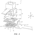
- FIG. 2 is an exploded perspective view of an example of a camera module of a conventional module tilt type.
- camera module 2 of a conventional module tilt type includes fixing part 21, movable part 22, elastic supporting part 23, imaging module 24, and shake detection part 25.
- An OIS actuator is composed of fixing part 21, movable part 22, and elastic supporting part 23.
- Fixing part 21 includes base member 211, coil part 212, and OIS print wiring board 213.
- Coil part 212 is disposed to base member 211.
- OIS print wiring board 213 feeds power to coil part 212, and outputs a detection signal of shake detection part 25 to a control part.
- Movable part 22 includes yoke 221, magnet part 222, top plate 223, and module guide 224. Yoke 221 and magnet part 222 are disposed to respective housing parts formed in top plate 223. Module guide 224 is fixed to top plate 223. Imaging module 24 is disposed and fixed in a space sandwiched between a pair of module guides 224.
- Elastic supporting part 23 has a biaxial gimbal mechanism, and movable part 22 (top plate 223) is fixed to an outer gimbal. Elastic supporting part 23 is disposed at an approximate center of base member 211 in a floating fashion, and fixed by stopper 231. Elastic supporting part 23 supports movable part 22 such that movable part 22 can rotationally sway around the X axis and the Y axis orthogonal to the optical axis (Z axis), that is, elastic supporting part 23 supports movable part 22 such that movable part 22 can be tilted.
- Shake detection part 25 is composed of a gyro sensor that detects the angular velocity of imaging module 24, for example. Shake detection part 25 is fixed to a side surface of module guide 224 of movable part 22. The detection signal of shake detection part 25 is output to the control part through OIS print wiring board 213 that is fixing part 21.
- An OIS voice coil motor is composed of coil part 212 and magnet part 222. That is, when a current flows through coil part 212, a Lorentz force is generated at coil part 212 with interaction between the magnetic field of magnet part 222 and a current flowing through coil part 212 (Fleming's left hand rule). Since coil part 212 is fixed, a reactive force is exerted on magnet part 222. This reactive force is the driving force of the OIS voice coil motor. Movable part 22 rotationally sways until the driving force of the OIS voice coil motor and the restoration force (returning force) of elastic supporting part 23 become equivalent to each other. In this manner, shift of the optical axis due to hand shake is corrected, and the orientation of the light axis is kept at an orientation.
- PTL 2 discloses a configuration where a bobbin as a part of a movable part is mounted on an elastic member.
- the elastic member includes a first frame unit at its center part, a second frame unit at its outer part, and an elastic unit connecting the first and second frame unit.
- An object of the present invention is to provide an actuator, a camera module and a camera-equipped mobile terminal which can achieve an improved shake correction.
- An actuator corrects shake by tilting a driven part with a driving force of a voice coil motor including a coil part and a magnet part, and includes: a movable part including a holding member having a flat frame shape on which the driven part is bonded, and one of the coil part and the magnet part disposed to the holding member; a fixing part including a base member, a cover member having a frame shape fixed to a peripheral portion of the base member, and the other of the coil part and the magnet part disposed to the base member; a supporting part disposed to the base member, and configured to support the movable part such that the movable part is allowed to be tilted with respect to the fixing part.
- the movable part is tightly sandwiched between the base member and the cover member.
- a camera module includes: the above-mentioned actuator; an imaging module including a lens part and an imaging device, and bonded to the holding member as the driven part; and a shake detection part configured to detect shake of the imaging module.
- a camera-equipped mobile terminal includes the above-mentioned camera module.
- the number of components is small in comparison with the conventional technique, and therefore it is possible to achieve further height reduction and facilitation of assembling processes.
- FIGS. 3A and 3B illustrate smartphone M in which camera module 1 according to an embodiment of the present invention is mounted.
- FIG. 3A is a front view of smartphone M
- FIG. 3B is a rear view of smartphone M.
- smartphone M is provided with camera module 1 as a back side camera OC.
- Camera module 1 has an auto-focusing function and a hand-shake correction function, and can capture an image without image blurring by automatically performing focusing at the time of capturing a subject and by correcting hand shake (vibration) caused at the time of capturing an image.
- the hand-shake correction function of camera module 1 is of a module tilt type.
- the module tilt type is advantageous in that no deformation is caused at four corners of the screen.
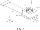
- FIG. 4 is a perspective view of an external appearance of camera module 1.
- FIG. 5 is an exploded perspective view of camera module 1.
- FIG. 6 is a sectional view of camera module 1 along the Y direction.
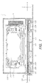
- FIG. 7 is a sectional view of camera module 1 along the X direction.
- Camera module 1 is mounted such that the vertical direction (or horizontal direction) is the X direction, the horizontal direction (or vertical direction) is the Y direction, and the front-rear direction is the Z direction at the time of actually capturing an image with smartphone M.
- camera module 1 includes fixing part 11, movable part 12, elastic supporting part 13, imaging module 14, shake detection part 15 and the like.
- OIS actuator A is composed of fixing part 11, movable part 12, and elastic supporting part 13.
- hand-shake correction is performed with use of the driving force of an OIS voice coil motor including coil part 112 and magnet part 122.
- Fixing part 11 is fixed so as to be unmovable when mounted in smartphone M.
- Fixing part 11 includes base member 111, coil part 112, OIS print wiring board 113, skirt member 114, and cover member 115.
- Base member 111 is a member formed of a metal material in a substantially rectangular shape.
- Base member 111 is formed of a metal, and as a result the strength is high in comparison with the case where base member 111 is formed of a resin.
- the thickness of base member 111 can be reduced, and in turn, reduction of the height of camera module 1 can be achieved.
- Base member 111 includes, at the center thereof, protruding part 111a having a truncated pyramid shape for fixing elastic supporting part 13.
- Base member 111 includes, at positions around protruding part 111a, upright pieces 111b for setting the position of coil part 112.
- Base member 111 includes, at respective both end portions of the peripheral portions along the X direction, lock pieces 111c for fixing skirt member 114. Lock pieces 111c generate an outward biasing force in the Y direction when skirt member 114 is attached to base member 111.
- Base member 111 includes, at the four corners thereof, power feeding pads 111d for supplying electricity to coil part 112.
- Coil part 112 is composed of four tilt coils 112A to 112D and is disposed at base member 111 to surround protruding part 111a. The position of coil part 112 is set with upright pieces 111b of base member 111. Power is fed to coil part 112 through power feeding pad 111d.
- Tilt coils 112A and 112C face each other in the X direction, and tilt coils 112A and 112C are used to rotationally sway movable part 12 around the Y axis.
- Tilt coils 112B and 112D face each other in the Y direction, and tilt coils 112B and 112D are used to rotationally sway movable part 12 around the X axis.
- OIS print wiring board 113 includes a power-source line (not illustrated) for feeding power to coil part 112.
- OIS print wiring board 113 is fixed on the bottom surface of base member 111, and the power-source line is electrically connected with power feeding pad 111 of base member 111.
- Skirt member 114 is a frame-shaped member composed of four walls coupled with each other in a rectangular shape, and includes reception port 114a for imaging module 14. Skirt member 114 includes lock parts 114b at positions corresponding to lock pieces 111c of base member 111. The upper part of the wall of one side of skirt member 114 is cut out, and is used as drawing part 114c for pulling out print wiring board 143 of imaging module 14. The upper parts of the remaining three side walls of skirt member 114 are formed to slightly protrude toward the inside, and serve as restriction part 114d for preventing movable part 12 from being excessively tilted.
- Skirt member 114 is fixed to the peripheral portion of base member 111 after movable part 12 is attached to base member 111 through elastic supporting part 13. Movable part 12 is tightly sandwiched between base member 111 and skirt member 114.
- Cover member 115 is a capped rectangular cylindrical member. Cover member 115 includes, at the top surface thereof, opening 115a through which lens part 141 of imaging module 14 faces outside. Cover member 115 is fixed to skirt member 114 after OIS actuator A is mounted to imaging module 14.
- Movable part 12 rotationally sways around the X axis and the Y axis with respect to fixing part 11.
- Movable part 12 includes yoke 121 and magnet part 122.
- yoke 121 directly holds imaging module 14.
- Imaging module 14 is bonded on the top surface of yoke 121 with double-sided tape 123, for example. Imaging module 14 may be bonded to yoke 121 with a resin adhesive agent instead of double-sided tape 123.
- imaging module 14 can be fixed to yoke 121 with use of a jig while setting the position of imaging module 14 with high accuracy.
- Yoke 121 is a flat-frame shaped member composed of four flat plates which are formed of a magnetic material and are coupled with each other in a rectangular shape.
- Yoke 121 includes reception port 121a for imaging module 14.
- Yoke 121 includes outer leg parts 121b formed in a downward eaves shape which are disposed along the outer peripheral edges of respective flat plates.
- Yoke 121 includes inner leg parts 121c formed in a downward protruding shape which are disposed along the inner peripheral edges of respective flat plates. That is, the cross-sectional shape of one side of yoke 121 partially has a U-shape or an L-shape.
- yoke 121 includes, at the four corners of the inner peripheral edge thereof, fixation pieces 121d for fixing elastic supporting part 13.
- Magnet part 122 is composed of four cuboid permanent magnets 122A to 122D corresponding to tilt coils 112A to 112D. Electromagnets may be used in place of permanent magnets. Permanent magnets 122A to 122D have a size which can be put inside tilt coils 112A to 112D.
- Permanent magnets 122A to 122D are disposed at the bottom surfaces of respective flat plates of yoke 121 such that the magnetization direction is the Z direction, and permanent magnets 122A to 122D are fixed by bonding, for example. With use of a jig, permanent magnets 122A to 122D can be fixed to yoke 121 while setting the positions with high accuracy. Permanent magnets 122A to 122D are located between inner leg part 121c and outer leg part 121b of yoke 121.
- coil part 112 is located between yoke 121 and magnet part 122 (see FIGS. 5 to 6 ). Since the periphery of coil part 112 is covered with yoke 121, it is possible to prevent the AF actuator of imaging module 14 from being unfavorably influenced by the magnetic field of the energization current of coil part 112.
- Elastic supporting part 13 is composed of a rectangular member having a biaxial gimbal mechanism (so-called gimbal spring). To be more specific, as illustrated in FIG. 8 , elastic supporting part 13 includes center portion 13a and outer gimbal 13c continuously connected with center portion 13a with inner gimbal 13b therebetween. Outer gimbal 13c rotationally sways around the X axis and the Y axis. Inner gimbal 13b has a complex curved shape, and outer gimbal 13c has a shape of a rectangular frame.
- Imaging module 14 includes lens part 141, an imaging device (not illustrated), AF actuator 142, and AF print wiring board 143.
- the imaging device is composed of, for example, a CCD (charge coupled device) image sensor, a CMOS (complementary metal oxide semiconductor) image sensor, or the like.
- the imaging device is mounted to AF print wiring board 143.
- the imaging device captures a subject image imaged by lens part 141.
- AF actuator 142 includes an AF voice coil motor for example, and moves lens part 141 in the light axis direction by utilizing the driving force of AF voice coil motor.
- Publicly known techniques can be applied to AF actuator 142.
- AF print wiring board 143 includes a power-source line (not illustrated) configured to feed power to a coil part (not illustrated) of AF actuator 142, and a video signal line (not illustrated) for video signals output from the imaging device, and a detection signal line (not illustrated) for detection signals output from shake detection part 15.
- AF print wiring board 143 is pulled to the outside through drawing part 114c of skirt member 114 in the state where imaging module 14 is mounted in OIS actuator A. Branching may be provided in AF print wiring board 143 to attach different connectors to the video signal line and the detection signal line.
- Shake detection part 15 detects shake (movement) of imaging module 14.
- Shake detection part 15 is composed of a gyro sensor configured to detect the angular velocity of imaging module 14, for example.
- Shake detection part 15 is mounted to upright part 143a of AF print wiring board 143.
- the detection signal of shake detection part 15 is output to a control part through AF print wiring board 143.
- the control part controls the energization current of coil part 112 based on the detection signal.
- control part (not illustrated) may be mounted to AF print wiring board 143, or the control part mounted in smartphone M may be utilized.
- shake detection part 25 is attached to movable part 22 (module guide 224), and the detection signal of shake detection part 25 is output through OIS print wiring board 213 serving as fixing part 21.
- OIS print wiring board 213 serving as fixing part 21.
- the rotational sway of movable part 22 is inhibited by OIS print wiring board 213, and the sensitivity of the tilt operation is reduced, and as a result, the driving force of the OIS actuator is inevitably increased.
- the detection signal of shake detection part 15 is output through AF print wiring board 143 of imaging module 14. That is, OIS print wiring board 113 of fixing part 11 does not inhibit the rotational sway of movable part 12 (imaging module 14). Accordingly, the driving force of OIS actuator A can be reduced in comparison with the conventional technique, and the power consumption can be reduced. In addition, OIS print wiring board 113 of fixing part 11 is used only for power feeding to coil part 112, and therefore may be omitted by separately providing another power-source line. Consequently, cost reduction and space-saving can be achieved.
- the OIS voice coil motor is composed of coil part 112 and magnet part 122.
- imaging module 14 movable part 12
- the optical axis coincides with the Z direction.
- movable part 12 including imaging module 14 rotationally sways around the Y axis with center portion 13a of elastic supporting part 13 as a fulcrum.
- movable part 12 including imaging module 14 rotationally sways around the X axis with center portion 13a of elastic supporting part 13 as a fulcrum.
- Movable part 12 rotationally sways until the driving force of the OIS voice coil motor (force which acts on magnet part 122) and the restoration force of elastic supporting part 13 become equivalent to each other.
- the energization current of coil part 112 is controlled based on the detection result of shake detection part 15 such that rotational sway of movable part 12 offsets shake of imaging module 14. In this manner, the shift of the optical axis due to hand shake is corrected, and the orientation of the light axis is kept at an orientation.
- restriction part 114d of skirt member 114 limits the rotational sway of movable part 12, it is possible to prevent movable part 12 from being excessively rotationally swayed by the drop impact or the like.
- actuator A corrects shake by tilting the driven part (imaging module 14) with the driving force of the voice coil motor including coil part (112) and magnet part (122).
- Actuator A includes: movable part (12) in which a holding member (yoke 121) having a flat frame shaped on which the driven part (imaging module 14) is bonded is provided and magnet part (122) is disposed to holding member (121); fixing part (11) in which base member (111) and a cover member (skirt member 114) having a frame shape fixed to a peripheral portion of base member (111) are provided and coil part (112) is disposed to base member (111); and a supporting part (elastic supporting part 13) disposed to base member (111) and configured to support movable part (12) such that movable part (12) can be tilted with respect to fixing part (11). Movable part (12) is tightly sandwiched between base member (111) and cover member (114).
- camera module 1 is obtained by only bonding imaging module 14 with an auto-focusing function to yoke 121.
- the actuator of the embodiment is of a so-called moving magnet type in which fixing part 11 includes coil part 112 and movable part 12 includes magnet part 122
- the present invention may be applied to an actuator of a so-called moving coil type in which a fixing part includes a magnet part and a movable part includes a coil part.
- the yoke is also disposed to the fixing part.
- two pairs of tilt coil 112A and permanent magnet 122A and tilt coil 112C and permanent magnet 122C are disposed as the voice coil motor that rotationally sways movable part 12 around the X axis
- two pairs of tilt coil 112B and permanent magnet 122B and tilt coil 112D and permanent magnet 122D are disposed as the voice coil motor that rotationally sways movable part 12 around the Y axis
- at least one pair is disposed as each of the voice coil motors.
- shake detection part 15 photo reflectors, magnetic sensors, inductance detection with a coil, strain sensors and the like may also be adopted as well as gyro sensors.
- a detection device for example a photodetector of a photo reflector, a Hall device of a magnetic sensor or the like
- each component (in particular, magnet part 122) of actuator A is formed of a highly heat-resistant material. In this manner, soldering of a reflow type can be employed.
- a conductive shield case may be provided on the outside of camera module 1.
- While a smartphone is described in the embodiment as an example of the camera-equipped mobile terminal, the present invention is also applicable to camera-equipped mobile phones, note-type personal computers, tablet terminals, mobile game machines, webcameras, in-vehicle cameras and the like.
Landscapes
- Physics & Mathematics (AREA)
- General Physics & Mathematics (AREA)
- Engineering & Computer Science (AREA)
- Signal Processing (AREA)
- Multimedia (AREA)
- Optics & Photonics (AREA)
- Adjustment Of Camera Lenses (AREA)
- Studio Devices (AREA)
Applications Claiming Priority (2)
| Application Number | Priority Date | Filing Date | Title |
|---|---|---|---|
| JP2014091874A JP6311434B2 (ja) | 2014-04-25 | 2014-04-25 | アクチュエーター、カメラモジュール、及びカメラ付き携帯端末 |
| PCT/JP2015/002184 WO2015162917A1 (ja) | 2014-04-25 | 2015-04-22 | アクチュエーター、カメラモジュール、及びカメラ付き携帯端末 |
Publications (3)
| Publication Number | Publication Date |
|---|---|
| EP3136166A1 EP3136166A1 (en) | 2017-03-01 |
| EP3136166A4 EP3136166A4 (en) | 2017-11-15 |
| EP3136166B1 true EP3136166B1 (en) | 2020-06-24 |
Family
ID=54332093
Family Applications (1)
| Application Number | Title | Priority Date | Filing Date |
|---|---|---|---|
| EP15783578.6A Not-in-force EP3136166B1 (en) | 2014-04-25 | 2015-04-22 | Actuator, camera module, and mobile terminal with camera |
Country Status (7)
| Country | Link |
|---|---|
| US (1) | US9746690B2 (enExample) |
| EP (1) | EP3136166B1 (enExample) |
| JP (1) | JP6311434B2 (enExample) |
| KR (1) | KR102292067B1 (enExample) |
| CN (1) | CN106233197B (enExample) |
| TW (1) | TWI662770B (enExample) |
| WO (1) | WO2015162917A1 (enExample) |
Families Citing this family (28)
| Publication number | Priority date | Publication date | Assignee | Title |
|---|---|---|---|---|
| JP6507628B2 (ja) * | 2014-12-24 | 2019-05-08 | ミツミ電機株式会社 | アクチュエーター、カメラモジュール及びカメラ搭載装置 |
| JP6488161B2 (ja) * | 2015-03-13 | 2019-03-20 | オリンパス株式会社 | ブレ補正装置 |
| US10353216B2 (en) * | 2015-07-14 | 2019-07-16 | Nidec Sankyo Corporation | Optical unit with shake correction function and its manufacturing method |
| CN107238910B (zh) * | 2016-03-29 | 2023-08-15 | 台湾东电化股份有限公司 | 镜头驱动装置 |
| US9958756B2 (en) | 2016-05-20 | 2018-05-01 | Tdk Taiwan Corp. | Camera module and image capturing unit thereof |
| CN108319093B (zh) * | 2017-01-18 | 2021-08-06 | 三美电机株式会社 | 透镜驱动装置、摄像机模块以及摄像机搭载装置 |
| TWI781985B (zh) * | 2017-03-09 | 2022-11-01 | 美商康寧公司 | 具有自動對焦與光學圖像穩定功能的相機模組 |
| CN207010790U (zh) * | 2017-04-17 | 2018-02-13 | 三赢科技(深圳)有限公司 | 成像模组 |
| JP6997370B2 (ja) * | 2017-05-25 | 2022-01-17 | ミツミ電機株式会社 | カメラ用アクチュエータ、カメラモジュール、およびカメラ搭載装置 |
| CN108931874A (zh) * | 2017-05-27 | 2018-12-04 | 新思考电机有限公司 | 双轴倾斜活动装置、照相装置、光学装置以及电子设备 |
| CN109143721B (zh) * | 2017-06-27 | 2024-03-15 | 新思考电机有限公司 | 光学部件用倾斜活动装置、摄像装置、光学装置以及电子设备 |
| CN107329348B (zh) * | 2017-07-12 | 2022-12-30 | 惠州萨至德光电科技有限公司 | 一种带防抖功能的透镜驱动装置 |
| CN107315302B (zh) * | 2017-08-25 | 2020-03-31 | 高瞻创新科技有限公司 | 一种具有多自由度的电路板及防抖微型致动器 |
| WO2019216590A1 (en) | 2018-05-11 | 2019-11-14 | Lg Electronics Inc. | Camera for electronic device |
| CN109343294B (zh) * | 2018-10-25 | 2024-05-31 | 信利光电股份有限公司 | 潜望式防抖模组及潜望式摄像模组 |
| KR102638527B1 (ko) | 2018-11-13 | 2024-02-21 | 엘지이노텍 주식회사 | 엑추에이터 |
| CN111193346A (zh) * | 2018-11-15 | 2020-05-22 | 三赢科技(深圳)有限公司 | 音圈马达 |
| CN111212199B (zh) | 2018-11-21 | 2025-08-08 | 北京小米移动软件有限公司 | 驱动机构、摄像头模组及电子设备 |
| US20200236254A1 (en) * | 2019-01-23 | 2020-07-23 | Black Seasme International Holding Limited | Camera system with reduced alignment shift |
| KR102901981B1 (ko) | 2019-11-18 | 2025-12-18 | 엘지이노텍 주식회사 | 카메라 모듈 및 광학 기기 |
| CN111212214B (zh) | 2020-03-19 | 2021-11-30 | 维沃移动通信有限公司 | 防抖机构、摄像头模组及电子设备 |
| JP7538402B2 (ja) * | 2020-03-31 | 2024-08-22 | ミツミ電機株式会社 | 光学アクチュエータ、カメラモジュール、及びカメラ搭載装置 |
| WO2021256736A1 (ko) | 2020-06-17 | 2021-12-23 | 엘지이노텍(주) | 카메라 모듈 및 광학 기기 |
| JP7493421B2 (ja) * | 2020-10-02 | 2024-05-31 | ニデックインスツルメンツ株式会社 | 光学ユニット |
| JP7237914B2 (ja) * | 2020-12-21 | 2023-03-13 | ジョウシュウシ レイテック オプトロニクス カンパニーリミテッド | 撮像装置用防振機構、光学系、カメラ及び電子機器 |
| JP7137610B2 (ja) * | 2020-12-21 | 2022-09-14 | ジョウシュウシ レイテック オプトロニクス カンパニーリミテッド | 撮像装置用防振機構、光学系、カメラ及び電子機器 |
| CN112954185B (zh) * | 2021-04-19 | 2023-04-07 | 维沃移动通信有限公司 | 摄像头结构及电子设备 |
| US20250184588A1 (en) * | 2022-03-02 | 2025-06-05 | Lg Innotek Co., Ltd. | Camera module |
Citations (1)
| Publication number | Priority date | Publication date | Assignee | Title |
|---|---|---|---|---|
| US20120200176A1 (en) * | 2011-02-07 | 2012-08-09 | Lg Innotek Co., Ltd. | Multifunctional Voice Coil Motor |
Family Cites Families (7)
| Publication number | Priority date | Publication date | Assignee | Title |
|---|---|---|---|---|
| JP2007127755A (ja) * | 2005-11-02 | 2007-05-24 | Nikon Corp | 像振れ補正装置、光学装置、交換レンズ、及びカメラシステム |
| JP2007156351A (ja) * | 2005-12-08 | 2007-06-21 | Sony Corp | 像ぶれ補正装置、レンズ装置及び撮像装置 |
| JP2011027947A (ja) * | 2009-07-24 | 2011-02-10 | Nidec Sankyo Corp | 光学ユニット |
| JP5846346B2 (ja) * | 2009-08-21 | 2016-01-20 | ミツミ電機株式会社 | カメラの手振れ補正装置 |
| WO2011132920A2 (ko) * | 2010-04-20 | 2011-10-27 | 주식회사 뮤타스 | 카메라 모듈용 보이스 코일 모터 |
| JP5604237B2 (ja) * | 2010-09-09 | 2014-10-08 | 日本電産サンキョー株式会社 | 振れ補正機能付き光学ユニット |
| JP5768771B2 (ja) * | 2012-06-29 | 2015-08-26 | ミツミ電機株式会社 | カメラモジュール駆動装置およびカメラ付き携帯端末 |
-
2014
- 2014-04-25 JP JP2014091874A patent/JP6311434B2/ja not_active Expired - Fee Related
-
2015
- 2015-04-22 WO PCT/JP2015/002184 patent/WO2015162917A1/ja not_active Ceased
- 2015-04-22 US US15/305,868 patent/US9746690B2/en not_active Expired - Fee Related
- 2015-04-22 KR KR1020167026730A patent/KR102292067B1/ko not_active Expired - Fee Related
- 2015-04-22 EP EP15783578.6A patent/EP3136166B1/en not_active Not-in-force
- 2015-04-22 CN CN201580021240.2A patent/CN106233197B/zh active Active
- 2015-04-24 TW TW104113137A patent/TWI662770B/zh not_active IP Right Cessation
Patent Citations (1)
| Publication number | Priority date | Publication date | Assignee | Title |
|---|---|---|---|---|
| US20120200176A1 (en) * | 2011-02-07 | 2012-08-09 | Lg Innotek Co., Ltd. | Multifunctional Voice Coil Motor |
Also Published As
| Publication number | Publication date |
|---|---|
| EP3136166A1 (en) | 2017-03-01 |
| TWI662770B (zh) | 2019-06-11 |
| CN106233197A (zh) | 2016-12-14 |
| KR102292067B1 (ko) | 2021-08-19 |
| US9746690B2 (en) | 2017-08-29 |
| JP2015210387A (ja) | 2015-11-24 |
| JP6311434B2 (ja) | 2018-04-18 |
| EP3136166A4 (en) | 2017-11-15 |
| CN106233197B (zh) | 2019-05-21 |
| WO2015162917A1 (ja) | 2015-10-29 |
| US20170045753A1 (en) | 2017-02-16 |
| KR20160146680A (ko) | 2016-12-21 |
| TW201541821A (zh) | 2015-11-01 |
Similar Documents
| Publication | Publication Date | Title |
|---|---|---|
| EP3136166B1 (en) | Actuator, camera module, and mobile terminal with camera | |
| EP3239772B1 (en) | Actuator, camera module, and device including the camera module | |
| US20220014678A1 (en) | Lens drive apparatus, camera module and camera | |
| US10126522B2 (en) | Lens drive device, camera module, and mobile terminal with camera | |
| KR102354669B1 (ko) | 액추에이터, 카메라 모듈 및 카메라 탑재 장치 | |
| US10197887B2 (en) | Actuator, camera module, and camera mounted device | |
| JP6056883B2 (ja) | レンズ駆動装置、カメラモジュール、及びカメラ付き携帯端末 | |
| JP2014126668A (ja) | レンズ駆動装置、カメラモジュール、及びカメラ付き携帯端末 | |
| US12292679B2 (en) | Camera actuator, camera module, and camera mount device | |
| JP6492976B2 (ja) | アクチュエーター、カメラモジュール及びカメラ搭載装置 | |
| US12055839B2 (en) | Camera actuator, camera module, and camera mount device | |
| JP6365647B2 (ja) | レンズ駆動装置、カメラモジュール、及びカメラ付き携帯端末 | |
| HK1228020A1 (en) | Actuator, camera module, and mobile terminal with camera |
Legal Events
| Date | Code | Title | Description |
|---|---|---|---|
| STAA | Information on the status of an ep patent application or granted ep patent |
Free format text: STATUS: THE INTERNATIONAL PUBLICATION HAS BEEN MADE |
|
| PUAI | Public reference made under article 153(3) epc to a published international application that has entered the european phase |
Free format text: ORIGINAL CODE: 0009012 |
|
| STAA | Information on the status of an ep patent application or granted ep patent |
Free format text: STATUS: REQUEST FOR EXAMINATION WAS MADE |
|
| 17P | Request for examination filed |
Effective date: 20161020 |
|
| AK | Designated contracting states |
Kind code of ref document: A1 Designated state(s): AL AT BE BG CH CY CZ DE DK EE ES FI FR GB GR HR HU IE IS IT LI LT LU LV MC MK MT NL NO PL PT RO RS SE SI SK SM TR |
|
| AX | Request for extension of the european patent |
Extension state: BA ME |
|
| DAV | Request for validation of the european patent (deleted) | ||
| DAX | Request for extension of the european patent (deleted) | ||
| A4 | Supplementary search report drawn up and despatched |
Effective date: 20171018 |
|
| RIC1 | Information provided on ipc code assigned before grant |
Ipc: H04N 5/232 20060101ALI20171012BHEP Ipc: G02B 27/64 20060101ALI20171012BHEP Ipc: G02B 7/04 20060101ALI20171012BHEP Ipc: H04N 5/225 20060101ALI20171012BHEP Ipc: G03B 13/36 20060101ALI20171012BHEP Ipc: G03B 5/00 20060101AFI20171012BHEP |
|
| STAA | Information on the status of an ep patent application or granted ep patent |
Free format text: STATUS: EXAMINATION IS IN PROGRESS |
|
| 17Q | First examination report despatched |
Effective date: 20190110 |
|
| GRAP | Despatch of communication of intention to grant a patent |
Free format text: ORIGINAL CODE: EPIDOSNIGR1 |
|
| STAA | Information on the status of an ep patent application or granted ep patent |
Free format text: STATUS: GRANT OF PATENT IS INTENDED |
|
| INTG | Intention to grant announced |
Effective date: 20200103 |
|
| GRAS | Grant fee paid |
Free format text: ORIGINAL CODE: EPIDOSNIGR3 |
|
| GRAJ | Information related to disapproval of communication of intention to grant by the applicant or resumption of examination proceedings by the epo deleted |
Free format text: ORIGINAL CODE: EPIDOSDIGR1 |
|
| GRAL | Information related to payment of fee for publishing/printing deleted |
Free format text: ORIGINAL CODE: EPIDOSDIGR3 |
|
| STAA | Information on the status of an ep patent application or granted ep patent |
Free format text: STATUS: EXAMINATION IS IN PROGRESS |
|
| GRAR | Information related to intention to grant a patent recorded |
Free format text: ORIGINAL CODE: EPIDOSNIGR71 |
|
| STAA | Information on the status of an ep patent application or granted ep patent |
Free format text: STATUS: GRANT OF PATENT IS INTENDED |
|
| GRAA | (expected) grant |
Free format text: ORIGINAL CODE: 0009210 |
|
| STAA | Information on the status of an ep patent application or granted ep patent |
Free format text: STATUS: THE PATENT HAS BEEN GRANTED |
|
| INTC | Intention to grant announced (deleted) | ||
| AK | Designated contracting states |
Kind code of ref document: B1 Designated state(s): AL AT BE BG CH CY CZ DE DK EE ES FI FR GB GR HR HU IE IS IT LI LT LU LV MC MK MT NL NO PL PT RO RS SE SI SK SM TR |
|
| INTG | Intention to grant announced |
Effective date: 20200515 |
|
| REG | Reference to a national code |
Ref country code: GB Ref legal event code: FG4D |
|
| REG | Reference to a national code |
Ref country code: CH Ref legal event code: EP |
|
| REG | Reference to a national code |
Ref country code: AT Ref legal event code: REF Ref document number: 1284482 Country of ref document: AT Kind code of ref document: T Effective date: 20200715 |
|
| REG | Reference to a national code |
Ref country code: DE Ref legal event code: R096 Ref document number: 602015054758 Country of ref document: DE |
|
| REG | Reference to a national code |
Ref country code: IE Ref legal event code: FG4D |
|
| PG25 | Lapsed in a contracting state [announced via postgrant information from national office to epo] |
Ref country code: SE Free format text: LAPSE BECAUSE OF FAILURE TO SUBMIT A TRANSLATION OF THE DESCRIPTION OR TO PAY THE FEE WITHIN THE PRESCRIBED TIME-LIMIT Effective date: 20200624 Ref country code: LT Free format text: LAPSE BECAUSE OF FAILURE TO SUBMIT A TRANSLATION OF THE DESCRIPTION OR TO PAY THE FEE WITHIN THE PRESCRIBED TIME-LIMIT Effective date: 20200624 Ref country code: GR Free format text: LAPSE BECAUSE OF FAILURE TO SUBMIT A TRANSLATION OF THE DESCRIPTION OR TO PAY THE FEE WITHIN THE PRESCRIBED TIME-LIMIT Effective date: 20200925 Ref country code: NO Free format text: LAPSE BECAUSE OF FAILURE TO SUBMIT A TRANSLATION OF THE DESCRIPTION OR TO PAY THE FEE WITHIN THE PRESCRIBED TIME-LIMIT Effective date: 20200924 Ref country code: FI Free format text: LAPSE BECAUSE OF FAILURE TO SUBMIT A TRANSLATION OF THE DESCRIPTION OR TO PAY THE FEE WITHIN THE PRESCRIBED TIME-LIMIT Effective date: 20200624 |
|
| REG | Reference to a national code |
Ref country code: LT Ref legal event code: MG4D |
|
| PG25 | Lapsed in a contracting state [announced via postgrant information from national office to epo] |
Ref country code: LV Free format text: LAPSE BECAUSE OF FAILURE TO SUBMIT A TRANSLATION OF THE DESCRIPTION OR TO PAY THE FEE WITHIN THE PRESCRIBED TIME-LIMIT Effective date: 20200624 Ref country code: RS Free format text: LAPSE BECAUSE OF FAILURE TO SUBMIT A TRANSLATION OF THE DESCRIPTION OR TO PAY THE FEE WITHIN THE PRESCRIBED TIME-LIMIT Effective date: 20200624 Ref country code: HR Free format text: LAPSE BECAUSE OF FAILURE TO SUBMIT A TRANSLATION OF THE DESCRIPTION OR TO PAY THE FEE WITHIN THE PRESCRIBED TIME-LIMIT Effective date: 20200624 Ref country code: BG Free format text: LAPSE BECAUSE OF FAILURE TO SUBMIT A TRANSLATION OF THE DESCRIPTION OR TO PAY THE FEE WITHIN THE PRESCRIBED TIME-LIMIT Effective date: 20200924 |
|
| REG | Reference to a national code |
Ref country code: NL Ref legal event code: MP Effective date: 20200624 |
|
| REG | Reference to a national code |
Ref country code: AT Ref legal event code: MK05 Ref document number: 1284482 Country of ref document: AT Kind code of ref document: T Effective date: 20200624 |
|
| PG25 | Lapsed in a contracting state [announced via postgrant information from national office to epo] |
Ref country code: NL Free format text: LAPSE BECAUSE OF FAILURE TO SUBMIT A TRANSLATION OF THE DESCRIPTION OR TO PAY THE FEE WITHIN THE PRESCRIBED TIME-LIMIT Effective date: 20200624 Ref country code: AL Free format text: LAPSE BECAUSE OF FAILURE TO SUBMIT A TRANSLATION OF THE DESCRIPTION OR TO PAY THE FEE WITHIN THE PRESCRIBED TIME-LIMIT Effective date: 20200624 |
|
| PG25 | Lapsed in a contracting state [announced via postgrant information from national office to epo] |
Ref country code: CZ Free format text: LAPSE BECAUSE OF FAILURE TO SUBMIT A TRANSLATION OF THE DESCRIPTION OR TO PAY THE FEE WITHIN THE PRESCRIBED TIME-LIMIT Effective date: 20200624 Ref country code: IT Free format text: LAPSE BECAUSE OF FAILURE TO SUBMIT A TRANSLATION OF THE DESCRIPTION OR TO PAY THE FEE WITHIN THE PRESCRIBED TIME-LIMIT Effective date: 20200624 Ref country code: RO Free format text: LAPSE BECAUSE OF FAILURE TO SUBMIT A TRANSLATION OF THE DESCRIPTION OR TO PAY THE FEE WITHIN THE PRESCRIBED TIME-LIMIT Effective date: 20200624 Ref country code: PT Free format text: LAPSE BECAUSE OF FAILURE TO SUBMIT A TRANSLATION OF THE DESCRIPTION OR TO PAY THE FEE WITHIN THE PRESCRIBED TIME-LIMIT Effective date: 20201026 Ref country code: AT Free format text: LAPSE BECAUSE OF FAILURE TO SUBMIT A TRANSLATION OF THE DESCRIPTION OR TO PAY THE FEE WITHIN THE PRESCRIBED TIME-LIMIT Effective date: 20200624 Ref country code: ES Free format text: LAPSE BECAUSE OF FAILURE TO SUBMIT A TRANSLATION OF THE DESCRIPTION OR TO PAY THE FEE WITHIN THE PRESCRIBED TIME-LIMIT Effective date: 20200624 Ref country code: SM Free format text: LAPSE BECAUSE OF FAILURE TO SUBMIT A TRANSLATION OF THE DESCRIPTION OR TO PAY THE FEE WITHIN THE PRESCRIBED TIME-LIMIT Effective date: 20200624 Ref country code: EE Free format text: LAPSE BECAUSE OF FAILURE TO SUBMIT A TRANSLATION OF THE DESCRIPTION OR TO PAY THE FEE WITHIN THE PRESCRIBED TIME-LIMIT Effective date: 20200624 |
|
| PG25 | Lapsed in a contracting state [announced via postgrant information from national office to epo] |
Ref country code: SK Free format text: LAPSE BECAUSE OF FAILURE TO SUBMIT A TRANSLATION OF THE DESCRIPTION OR TO PAY THE FEE WITHIN THE PRESCRIBED TIME-LIMIT Effective date: 20200624 Ref country code: PL Free format text: LAPSE BECAUSE OF FAILURE TO SUBMIT A TRANSLATION OF THE DESCRIPTION OR TO PAY THE FEE WITHIN THE PRESCRIBED TIME-LIMIT Effective date: 20200624 Ref country code: IS Free format text: LAPSE BECAUSE OF FAILURE TO SUBMIT A TRANSLATION OF THE DESCRIPTION OR TO PAY THE FEE WITHIN THE PRESCRIBED TIME-LIMIT Effective date: 20201024 |
|
| REG | Reference to a national code |
Ref country code: DE Ref legal event code: R097 Ref document number: 602015054758 Country of ref document: DE |
|
| PG25 | Lapsed in a contracting state [announced via postgrant information from national office to epo] |
Ref country code: DK Free format text: LAPSE BECAUSE OF FAILURE TO SUBMIT A TRANSLATION OF THE DESCRIPTION OR TO PAY THE FEE WITHIN THE PRESCRIBED TIME-LIMIT Effective date: 20200624 |
|
| PLBE | No opposition filed within time limit |
Free format text: ORIGINAL CODE: 0009261 |
|
| STAA | Information on the status of an ep patent application or granted ep patent |
Free format text: STATUS: NO OPPOSITION FILED WITHIN TIME LIMIT |
|
| 26N | No opposition filed |
Effective date: 20210325 |
|
| PG25 | Lapsed in a contracting state [announced via postgrant information from national office to epo] |
Ref country code: SI Free format text: LAPSE BECAUSE OF FAILURE TO SUBMIT A TRANSLATION OF THE DESCRIPTION OR TO PAY THE FEE WITHIN THE PRESCRIBED TIME-LIMIT Effective date: 20200624 |
|
| REG | Reference to a national code |
Ref country code: DE Ref legal event code: R119 Ref document number: 602015054758 Country of ref document: DE |
|
| PG25 | Lapsed in a contracting state [announced via postgrant information from national office to epo] |
Ref country code: MC Free format text: LAPSE BECAUSE OF FAILURE TO SUBMIT A TRANSLATION OF THE DESCRIPTION OR TO PAY THE FEE WITHIN THE PRESCRIBED TIME-LIMIT Effective date: 20200624 |
|
| GBPC | Gb: european patent ceased through non-payment of renewal fee |
Effective date: 20210422 |
|
| PG25 | Lapsed in a contracting state [announced via postgrant information from national office to epo] |
Ref country code: LU Free format text: LAPSE BECAUSE OF NON-PAYMENT OF DUE FEES Effective date: 20210422 |
|
| REG | Reference to a national code |
Ref country code: BE Ref legal event code: MM Effective date: 20210430 |
|
| PG25 | Lapsed in a contracting state [announced via postgrant information from national office to epo] |
Ref country code: CH Free format text: LAPSE BECAUSE OF NON-PAYMENT OF DUE FEES Effective date: 20210430 Ref country code: LI Free format text: LAPSE BECAUSE OF NON-PAYMENT OF DUE FEES Effective date: 20210430 Ref country code: GB Free format text: LAPSE BECAUSE OF NON-PAYMENT OF DUE FEES Effective date: 20210422 Ref country code: FR Free format text: LAPSE BECAUSE OF NON-PAYMENT OF DUE FEES Effective date: 20210430 Ref country code: DE Free format text: LAPSE BECAUSE OF NON-PAYMENT OF DUE FEES Effective date: 20211103 |
|
| PG25 | Lapsed in a contracting state [announced via postgrant information from national office to epo] |
Ref country code: IE Free format text: LAPSE BECAUSE OF NON-PAYMENT OF DUE FEES Effective date: 20210422 |
|
| PG25 | Lapsed in a contracting state [announced via postgrant information from national office to epo] |
Ref country code: IS Free format text: LAPSE BECAUSE OF FAILURE TO SUBMIT A TRANSLATION OF THE DESCRIPTION OR TO PAY THE FEE WITHIN THE PRESCRIBED TIME-LIMIT Effective date: 20201024 |
|
| PG25 | Lapsed in a contracting state [announced via postgrant information from national office to epo] |
Ref country code: BE Free format text: LAPSE BECAUSE OF NON-PAYMENT OF DUE FEES Effective date: 20210430 |
|
| PG25 | Lapsed in a contracting state [announced via postgrant information from national office to epo] |
Ref country code: HU Free format text: LAPSE BECAUSE OF FAILURE TO SUBMIT A TRANSLATION OF THE DESCRIPTION OR TO PAY THE FEE WITHIN THE PRESCRIBED TIME-LIMIT; INVALID AB INITIO Effective date: 20150422 |
|
| PG25 | Lapsed in a contracting state [announced via postgrant information from national office to epo] |
Ref country code: CY Free format text: LAPSE BECAUSE OF FAILURE TO SUBMIT A TRANSLATION OF THE DESCRIPTION OR TO PAY THE FEE WITHIN THE PRESCRIBED TIME-LIMIT Effective date: 20200624 |
|
| PG25 | Lapsed in a contracting state [announced via postgrant information from national office to epo] |
Ref country code: MK Free format text: LAPSE BECAUSE OF FAILURE TO SUBMIT A TRANSLATION OF THE DESCRIPTION OR TO PAY THE FEE WITHIN THE PRESCRIBED TIME-LIMIT Effective date: 20200624 |
|
| PG25 | Lapsed in a contracting state [announced via postgrant information from national office to epo] |
Ref country code: TR Free format text: LAPSE BECAUSE OF FAILURE TO SUBMIT A TRANSLATION OF THE DESCRIPTION OR TO PAY THE FEE WITHIN THE PRESCRIBED TIME-LIMIT Effective date: 20200624 |
|
| PG25 | Lapsed in a contracting state [announced via postgrant information from national office to epo] |
Ref country code: MT Free format text: LAPSE BECAUSE OF FAILURE TO SUBMIT A TRANSLATION OF THE DESCRIPTION OR TO PAY THE FEE WITHIN THE PRESCRIBED TIME-LIMIT Effective date: 20200624 |