EP3136034A1 - Échangeur thermique - Google Patents
Échangeur thermique Download PDFInfo
- Publication number
- EP3136034A1 EP3136034A1 EP15783778.2A EP15783778A EP3136034A1 EP 3136034 A1 EP3136034 A1 EP 3136034A1 EP 15783778 A EP15783778 A EP 15783778A EP 3136034 A1 EP3136034 A1 EP 3136034A1
- Authority
- EP
- European Patent Office
- Prior art keywords
- refrigerant
- plates
- stack portion
- heat exchanger
- stacked
- Prior art date
- Legal status (The legal status is an assumption and is not a legal conclusion. Google has not performed a legal analysis and makes no representation as to the accuracy of the status listed.)
- Granted
Links
- 239000003507 refrigerant Substances 0.000 claims abstract description 109
- 239000002826 coolant Substances 0.000 claims abstract description 64
- 239000007791 liquid phase Substances 0.000 claims description 9
- 238000004519 manufacturing process Methods 0.000 description 4
- 239000007788 liquid Substances 0.000 description 3
- 238000000926 separation method Methods 0.000 description 3
- 239000000470 constituent Substances 0.000 description 2
- 239000012808 vapor phase Substances 0.000 description 2
- 230000002528 anti-freeze Effects 0.000 description 1
- 238000009434 installation Methods 0.000 description 1
- 238000000034 method Methods 0.000 description 1
- 238000005191 phase separation Methods 0.000 description 1
- 230000000717 retained effect Effects 0.000 description 1
- 238000007789 sealing Methods 0.000 description 1
Images


Classifications
-
- F—MECHANICAL ENGINEERING; LIGHTING; HEATING; WEAPONS; BLASTING
- F28—HEAT EXCHANGE IN GENERAL
- F28D—HEAT-EXCHANGE APPARATUS, NOT PROVIDED FOR IN ANOTHER SUBCLASS, IN WHICH THE HEAT-EXCHANGE MEDIA DO NOT COME INTO DIRECT CONTACT
- F28D9/00—Heat-exchange apparatus having stationary plate-like or laminated conduit assemblies for both heat-exchange media, the media being in contact with different sides of a conduit wall
- F28D9/0093—Multi-circuit heat-exchangers, e.g. integrating different heat exchange sections in the same unit or heat-exchangers for more than two fluids
-
- B—PERFORMING OPERATIONS; TRANSPORTING
- B60—VEHICLES IN GENERAL
- B60H—ARRANGEMENTS OF HEATING, COOLING, VENTILATING OR OTHER AIR-TREATING DEVICES SPECIALLY ADAPTED FOR PASSENGER OR GOODS SPACES OF VEHICLES
- B60H1/00—Heating, cooling or ventilating [HVAC] devices
- B60H1/32—Cooling devices
-
- F—MECHANICAL ENGINEERING; LIGHTING; HEATING; WEAPONS; BLASTING
- F25—REFRIGERATION OR COOLING; COMBINED HEATING AND REFRIGERATION SYSTEMS; HEAT PUMP SYSTEMS; MANUFACTURE OR STORAGE OF ICE; LIQUEFACTION SOLIDIFICATION OF GASES
- F25B—REFRIGERATION MACHINES, PLANTS OR SYSTEMS; COMBINED HEATING AND REFRIGERATION SYSTEMS; HEAT PUMP SYSTEMS
- F25B39/00—Evaporators; Condensers
-
- F—MECHANICAL ENGINEERING; LIGHTING; HEATING; WEAPONS; BLASTING
- F25—REFRIGERATION OR COOLING; COMBINED HEATING AND REFRIGERATION SYSTEMS; HEAT PUMP SYSTEMS; MANUFACTURE OR STORAGE OF ICE; LIQUEFACTION SOLIDIFICATION OF GASES
- F25B—REFRIGERATION MACHINES, PLANTS OR SYSTEMS; COMBINED HEATING AND REFRIGERATION SYSTEMS; HEAT PUMP SYSTEMS
- F25B43/00—Arrangements for separating or purifying gases or liquids; Arrangements for vaporising the residuum of liquid refrigerant, e.g. by heat
- F25B43/006—Accumulators
-
- F—MECHANICAL ENGINEERING; LIGHTING; HEATING; WEAPONS; BLASTING
- F28—HEAT EXCHANGE IN GENERAL
- F28D—HEAT-EXCHANGE APPARATUS, NOT PROVIDED FOR IN ANOTHER SUBCLASS, IN WHICH THE HEAT-EXCHANGE MEDIA DO NOT COME INTO DIRECT CONTACT
- F28D9/00—Heat-exchange apparatus having stationary plate-like or laminated conduit assemblies for both heat-exchange media, the media being in contact with different sides of a conduit wall
- F28D9/0031—Heat-exchange apparatus having stationary plate-like or laminated conduit assemblies for both heat-exchange media, the media being in contact with different sides of a conduit wall the conduits for one heat-exchange medium being formed by paired plates touching each other
- F28D9/0043—Heat-exchange apparatus having stationary plate-like or laminated conduit assemblies for both heat-exchange media, the media being in contact with different sides of a conduit wall the conduits for one heat-exchange medium being formed by paired plates touching each other the plates having openings therein for circulation of at least one heat-exchange medium from one conduit to another
- F28D9/005—Heat-exchange apparatus having stationary plate-like or laminated conduit assemblies for both heat-exchange media, the media being in contact with different sides of a conduit wall the conduits for one heat-exchange medium being formed by paired plates touching each other the plates having openings therein for circulation of at least one heat-exchange medium from one conduit to another the plates having openings therein for both heat-exchange media
-
- F—MECHANICAL ENGINEERING; LIGHTING; HEATING; WEAPONS; BLASTING
- F28—HEAT EXCHANGE IN GENERAL
- F28F—DETAILS OF HEAT-EXCHANGE AND HEAT-TRANSFER APPARATUS, OF GENERAL APPLICATION
- F28F3/00—Plate-like or laminated elements; Assemblies of plate-like or laminated elements
- F28F3/08—Elements constructed for building-up into stacks, e.g. capable of being taken apart for cleaning
- F28F3/086—Elements constructed for building-up into stacks, e.g. capable of being taken apart for cleaning having one or more openings therein forming tubular heat-exchange passages
-
- F—MECHANICAL ENGINEERING; LIGHTING; HEATING; WEAPONS; BLASTING
- F28—HEAT EXCHANGE IN GENERAL
- F28F—DETAILS OF HEAT-EXCHANGE AND HEAT-TRANSFER APPARATUS, OF GENERAL APPLICATION
- F28F9/00—Casings; Header boxes; Auxiliary supports for elements; Auxiliary members within casings
- F28F9/02—Header boxes; End plates
- F28F9/0246—Arrangements for connecting header boxes with flow lines
- F28F9/0251—Massive connectors, e.g. blocks; Plate-like connectors
-
- F—MECHANICAL ENGINEERING; LIGHTING; HEATING; WEAPONS; BLASTING
- F25—REFRIGERATION OR COOLING; COMBINED HEATING AND REFRIGERATION SYSTEMS; HEAT PUMP SYSTEMS; MANUFACTURE OR STORAGE OF ICE; LIQUEFACTION SOLIDIFICATION OF GASES
- F25B—REFRIGERATION MACHINES, PLANTS OR SYSTEMS; COMBINED HEATING AND REFRIGERATION SYSTEMS; HEAT PUMP SYSTEMS
- F25B2400/00—General features or devices for refrigeration machines, plants or systems, combined heating and refrigeration systems or heat-pump systems, i.e. not limited to a particular subgroup of F25B
- F25B2400/16—Receivers
-
- F—MECHANICAL ENGINEERING; LIGHTING; HEATING; WEAPONS; BLASTING
- F28—HEAT EXCHANGE IN GENERAL
- F28D—HEAT-EXCHANGE APPARATUS, NOT PROVIDED FOR IN ANOTHER SUBCLASS, IN WHICH THE HEAT-EXCHANGE MEDIA DO NOT COME INTO DIRECT CONTACT
- F28D21/00—Heat-exchange apparatus not covered by any of the groups F28D1/00 - F28D20/00
- F28D2021/0019—Other heat exchangers for particular applications; Heat exchange systems not otherwise provided for
- F28D2021/0061—Other heat exchangers for particular applications; Heat exchange systems not otherwise provided for for phase-change applications
- F28D2021/0063—Condensers
-
- F—MECHANICAL ENGINEERING; LIGHTING; HEATING; WEAPONS; BLASTING
- F28—HEAT EXCHANGE IN GENERAL
- F28D—HEAT-EXCHANGE APPARATUS, NOT PROVIDED FOR IN ANOTHER SUBCLASS, IN WHICH THE HEAT-EXCHANGE MEDIA DO NOT COME INTO DIRECT CONTACT
- F28D21/00—Heat-exchange apparatus not covered by any of the groups F28D1/00 - F28D20/00
- F28D2021/0019—Other heat exchangers for particular applications; Heat exchange systems not otherwise provided for
- F28D2021/0068—Other heat exchangers for particular applications; Heat exchange systems not otherwise provided for for refrigerant cycles
- F28D2021/007—Condensers
-
- F—MECHANICAL ENGINEERING; LIGHTING; HEATING; WEAPONS; BLASTING
- F28—HEAT EXCHANGE IN GENERAL
- F28D—HEAT-EXCHANGE APPARATUS, NOT PROVIDED FOR IN ANOTHER SUBCLASS, IN WHICH THE HEAT-EXCHANGE MEDIA DO NOT COME INTO DIRECT CONTACT
- F28D21/00—Heat-exchange apparatus not covered by any of the groups F28D1/00 - F28D20/00
- F28D2021/0019—Other heat exchangers for particular applications; Heat exchange systems not otherwise provided for
- F28D2021/0068—Other heat exchangers for particular applications; Heat exchange systems not otherwise provided for for refrigerant cycles
- F28D2021/0073—Gas coolers
Definitions
- the present invention relates to a heat exchanger.
- a conventional heat exchanger that transfers heat between a refrigerant and a coolant is integrally provided with a receiver tank (for example, see PTL 1).
- the receiver tank subjects the refrigerant to a vapor-liquid separation and adjusts an amount of the refrigerant.
- the heat exchanger disclosed in PTL 1 is structured by stacking a plurality of plates. With the stacking of the plates, passages for a coolant and passages for a refrigerant are alternately formed in a layered fashion. These passages constitute a heat exchange portion for the coolant and the refrigerant.
- the receiver tank is formed transversely of the heat exchange portion.
- a constituent element for the receiver tank is provided transversely of each part of the plates where the passage for a coolant or the passage for a refrigerant is formed. These constituent elements are stacked, so that the receiver tank is formed integrally with the heat exchange portion.
- the present invention provides a heat exchanger integrated with a receiver tank to have a structure that enables to allow both a capacity of the receiver tank and an area of a heat exchange portion to be adjusted at low cost at least when the heat exchanger is designed.
- the heat exchanger includes a first stack portion and a second stack portion.
- the first stack portion has a plurality of plates which are stacked, and a first refrigerant passage and a first coolant passage are formed between the plurality of plates.
- the second stack portion has a plurality of receiver components which are stacked, and a refrigerant retaining portion leading to the first refrigerant passage is formed in the plurality of receiver components.
- the second stack portion is stacked on the first stack portion in the same direction as a stacking direction in which the plurality of plates are stacked.
- both the capacity of the receiver tank and the area of the heat exchange portion can be adjusted at low cost at least when the heat exchanger is designed.
- a heat exchange portion is required to be designed to have a suitable size according to, for example, a performance of a heat pump system and a limited space in which the heat exchanger is to be positioned.
- a size of the heat exchange portion can be increased or reduced by changing a stacking number of the plates when the heat exchanger is designed.
- a receiver tank is required to be designed to have a suitable size according to, for example, the performance of the heat pump system and the limited space in which the heat exchanger is to be positioned.
- a capacity of the receiver tank can be increased or reduced by changing the stacking number of the plates when the heat exchanger is designed.
- the structure of the heat exchanger in PTL 1 has a disadvantage that the size of the heat exchange portion and the capacity of the receiver tank cannot be independently adjusted by changing the stacking number of the plates.
- the stacking number of the plates can be changed at low manufacturing cost.
- a shape change in the plates involves a change in a mold, and thus the cost is increased.
- FIG. 1 is a perspective view of a structure of heat exchanger 100 according to the exemplary embodiment of the present invention.
- FIG. 2 is an exploded perspective view of a plurality of plates constituting heat exchanger 100.
- FIG. 3 is a longitudinal sectional view of heat exchanger 100, taken at a line from a position of a refrigerant inlet to a position of a refrigerant outlet.
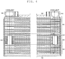
- FIG. 4 is a longitudinal sectional view of heat exchanger 100, taken at a line from a position of a coolant inlet to a position of a coolant outlet.
- Heat exchanger 100 transfers heat between a refrigerant and a coolant.
- Heat exchanger 100 is mainly formed of first stack portion 110, second stack portion 120, and third stack portion 130.
- Upper cover 140 is mounted on an upper part of the first stack portion 110, and lower cover 150 is mounted on a lower part of third stack portion 130.
- Upper cover 140 is provided with refrigerant inlet 141 that allows a high-pressure refrigerant compressed by a compressor to flow into first stack portion 110, coolant inlet 142 into which a coolant flows, and coolant outlet 143 of which a coolant subjected to a heat exchange flows out. Further, lower cover 150 is provided with refrigerant outlet 151 that allows a refrigerant subjected to a heat exchange to flow out of third stack portion 130.
- First stack portion 110 serves as a condenser. First stack portion 110 transfers heat between a high-temperature and high-pressure refrigerant delivered from the compressor and a coolant, causing the refrigerant to condense.
- the coolant is, for example, an antifreeze solution such as long life coolant (LLC) for use in transferring heat.
- LLC long life coolant
- first stack portion 110 includes a plurality of condenser plates 111 which are stacked.
- a passage for a refrigerant (refrigerant passage) and a passage for a coolant (coolant passage) are formed between the plurality of condenser plates 111.
- the passage for a refrigerant and the passage for a coolant are respectively referred to as first refrigerant passage 112 and first coolant passage 113.
- condenser plates 111a to 111f of different shapes are stacked, so that the refrigerant passage and the coolant passage are alternately formed between condenser plates 111.
- the refrigerant and the coolant respectively pass through the refrigerant passage and the coolant passage, without mixing each other.
- the refrigerant and the coolant respectively pass through the refrigerant passage and the coolant passage, flowing in directions opposite to each other.
- the refrigerant passes through the refrigerant passage and the coolant passes through the coolant passage, so that heat is transferred between the refrigerant and the coolant, causing the refrigerant to condense.
- FIG. 2 illustrates an exemplary case in which the refrigerant and the coolant respectively pass through the refrigerant passage and the coolant passage, flowing in directions opposite to each other.
- the configuration is not limited to this case.
- the refrigerant and the coolant may respectively pass through the refrigerant passage and the coolant passage, flowing in an identical direction.
- a size of first stack portion 110 (i.e., an area of a heat exchange portion) is adjusted by changing a stacking number of condenser plates 111c and condenser plates 111d when heat exchanger 100 is designed.
- Second stack portion 120 serves as a receiver tank. Second stack portion 120 retains a refrigerant flowed from first stack portion 110, subjects the refrigerant to a vapor-liquid separation, and adjusts an amount of the refrigerant.
- second stack portion 120 includes a plurality of receiver plates 121 which are stacked.
- Receiver plate 121 is shaped like a window frame with a central hole.
- Receiver plates 121 are stacked on condenser plates 111 to be continuous to condenser plates 111.
- second stack portion 120 is stacked on first stack portion 110 in a direction in which condenser plates 111 are stacked.
- refrigerant retaining portion 122 leading to the passage for a refrigerant of first stack portion 110 is formed inside stacked receiver plates 121. That is, stacked receiver plates 121 constitute a side of refrigerant retaining portion 122; a lowermost plate of first stack portion 110 (i.e., condenser plate 111f) serves as an upper surface of refrigerant retaining portion 122; and an uppermost plate of third stack portion 130 (subcool plate 131a), which is described later, serves as a lower surface of refrigerant retaining portion 122.
- the refrigerant delivered from first stack portion 110 passes through refrigerant passage aperture 124 of the second stack portion 120, and flows into refrigerant retaining portion 122 from a lowermost portion of second stack portion 120.
- a vapor-phase refrigerant in addition to a liquid-phase refrigerant, may mix with the refrigerant flowed from first stack portion 110 (condenser).
- Refrigerant retaining portion 122 subjects the refrigerant to a vapor-liquid separation, moves the vapor-phase refrigerant vertically upward, and moves the liquid-phase refrigerant vertically downward.
- a lower part of refrigerant retaining portion 122 serves as a retaining part for the liquid-phase refrigerant.
- a coolant having passed through first stack portion 110 passes through second stack portion 120 via coolant passage 123, and flows into third stack portion 130.
- Each condenser plate 111 and each receiver plate 121 have an identical size in a stacking direction in which condenser plates 111 and receiver plates 121 are stacked. Further, outlines and sizes of each condenser plate 111 and outlines and sizes of each receiver plate 121 in orthogonal projection onto a surface perpendicular to the stacking direction are identical to each other.
- a size of second stack portion 120 (i.e., a capacity of the receiver tank) is adjusted by changing a stacking number of receiver plates 121 when heat exchanger 100 is designed.
- Third stack portion 130 serves as a subcool part. In third stack portion 130, heat is transferred between the refrigerant flowed from second stack portion 120 (receiver tank) and the coolant flowed from first stack portion 110. Thus, third stack portion 130 additionally cools a liquid-phase refrigerant condensed in first stack portion 110.
- third stack portion 130 includes a plurality of subcool plates 131 which are stacked. Condenser plates 111, receiver plates 121, and subcool plates 131 are successively stacked. Thus, third stack portion 130 is stacked on second stack portion 120 in the direction in which condenser plates 111 and receiver plates 121 are stacked.
- a refrigerant passage for subcooling and a coolant passage for subcooling are formed between the plurality of subcool plates 131.
- the refrigerant passage for subcooling and the coolant passage for subcooling are respectively referred to as second refrigerant passage 132 and second coolant passage 133. Specifically, as illustrated in FIG.
- subcool plates 131a to 131d of different shapes are stacked, so that the refrigerant passage for subcooling and the coolant passage for subcooling are alternately formed between subcool plates 131.
- the refrigerant and the coolant respectively pass through the refrigerant passage and the coolant passage, without mixing each other.
- the refrigerant and the coolant respectively pass through the refrigerant passage and the coolant passage, flowing in directions opposite to each other.
- the refrigerant passes through the refrigerant passage and the coolant passes through the coolant passage, so that heat is transferred between the refrigerant and the coolant, causing a liquid-phase refrigerant to be further cooled.
- a size of third stack portion 130 (i.e., an area of a heat exchange portion) is adjusted by changing a stacking number of subcool plates 131c and subcool plates 131d which are alternately stacked when heat exchanger 100 is designed.
- first stack portion 110, second stack portion 120, and third stack portion 130 are sequentially stacked in this order. Further, the passage for a refrigerant in first stack portion 110 leads to refrigerant retaining portion 122 of second stack portion 120. The retaining part for a liquid-phase refrigerant in refrigerant retaining portion 122 leads to the passage for a refrigerant in third stack portion 130.
- a refrigerant flowed from refrigerant inlet 141 passes through the refrigerant passages that are alternately formed with the coolant passages in first stack portion 110, to condense, and flows into second stack portion 120 (receiver tank).
- the refrigerant that flows into refrigerant retaining portion 122 of second stack portion 120 is subjected to a liquid-phase separation, and an amount of the refrigerant is adjusted.
- a liquid-phase refrigerant flows into third stack portion 130, passes through the refrigerant passages that are alternately formed with the coolant passages, to be further cooled, and then flows out of refrigerant outlet 151.
- a coolant flowed from coolant inlet 142 passes through the coolant passages that are alternately formed with the refrigerant passages in first stack portion 110 (condenser) and in third stack portion 130 (subcool part) to which coolant passage 123 leads, to absorb heat from a refrigerant, and flows out of coolant outlet 143.
- condenser plates 111, receiver plates 121, and subcool plates 131 are successively stacked in an identical direction, to form a condenser (first stack portion 110), a receiver tank (second stack portion 120), and a subcool part (third stack portion 130), respectively.
- a size of the condenser and the subcool part can be adjusted by adjusting the stacking number of condenser plates 111 and subcool plates 131 according to, for example, a performance of a heat pump system, and a limited space in which heat exchanger 100 is to be positioned.
- a capacity of the receiver tank can be adjusted by changing the stacking number of receiver plates 121 according to, for example, a performance of a heat pump system, and a limited space in which heat exchanger 100 is to be positioned.
- the size of the heat exchange portion and the capacity of the receiver tank can be independently adjusted by individually changing the stacking number of condenser plates 111, the stacking number of receiver plates 121, and the stacking number of subcool plates 131.
- heat exchanger 100 can be structured to meet any of the different specifications by changing the stacking number of the respective plates.
- the structure of heat exchanger 100 can be adjusted by changing the stacking number of the plates, so that for example, commonality of a mold for the plates is achieved.
- the manufacturing cost can be reduced.
- each condenser plate 111 and each receiver plate 121 have an identical size in the direction in which condenser plates 111 and receiver plates 121 are stacked. Additionally, shapes of condenser plates 111 and receiver plates 121 are identical. Accordingly, heat exchanger 100 can be manufactured at low cost using a method for manufacturing a typical plate heat exchanger.
- the condenser, the receiver tank, and the subcool part are integrally formed, so that piping for connecting these components, and a sealing are eliminated. This eliminates a possibility of a leak at a joint, and results in low manufacturing cost.
- both the capacity of the receiver tank and an area of the heat exchange portion can be independently adjusted at low cost at least when the heat exchanger is designed.
- refrigerant retaining portion 122 is constituted by the holes formed in receiver plates 121, as illustrated in FIG. 2 .
- receiver plate 121 does not need to be shaped like a window frame with a hole.
- Receiver plate 121 may be shaped like a plate without a hole, such as condenser plate 111 and subcool plate 131.
- a passage for a refrigerant is formed between receiver plates 121, and a refrigerant is retained in the passages.
- heat exchanger 100 is exemplarily positioned such that upper cover 140 faces vertically upward and lower cover 150 faces vertically downward.
- the position of heat exchanger 100 in use is not limited to such a position.
- heat exchanger 100 in use may be positioned such that coolant inlet 142 and refrigerant outlet 151 face vertically upward and refrigerant inlet 141 and coolant outlet 143 face vertically downward.
- the size of receiver plate 121 is identical to that of condenser plate 111 or subcool plate 131 in the direction in which receiver plates 121, condenser plates 111, and subcool plates 131 are stacked.
- receiver components that constitute second stack portion 120 do not need to be shaped like a plate or a window frame that has a thickness sufficiently smaller than a breadth.
- the receiver components may each be shaped to have a large thickness.
- Second stack portion 120 may be provided by a plurality of receiver components each having a large thickness, which are stacked.
- the present invention is applicable to an air conditioner mounted in a vehicle.
Landscapes
- Engineering & Computer Science (AREA)
- Physics & Mathematics (AREA)
- Thermal Sciences (AREA)
- Mechanical Engineering (AREA)
- General Engineering & Computer Science (AREA)
- Chemical & Material Sciences (AREA)
- Analytical Chemistry (AREA)
- Power Engineering (AREA)
- Heat-Exchange Devices With Radiators And Conduit Assemblies (AREA)
- Air-Conditioning For Vehicles (AREA)
Applications Claiming Priority (2)
| Application Number | Priority Date | Filing Date | Title |
|---|---|---|---|
| JP2014091419A JP6315191B2 (ja) | 2014-04-25 | 2014-04-25 | 熱交換器 |
| PCT/JP2015/002223 WO2015162936A1 (fr) | 2014-04-25 | 2015-04-24 | Échangeur thermique |
Publications (3)
| Publication Number | Publication Date |
|---|---|
| EP3136034A1 true EP3136034A1 (fr) | 2017-03-01 |
| EP3136034A4 EP3136034A4 (fr) | 2017-06-07 |
| EP3136034B1 EP3136034B1 (fr) | 2018-07-04 |
Family
ID=54332110
Family Applications (1)
| Application Number | Title | Priority Date | Filing Date |
|---|---|---|---|
| EP15783778.2A Not-in-force EP3136034B1 (fr) | 2014-04-25 | 2015-04-24 | Échangeur thermique |
Country Status (4)
| Country | Link |
|---|---|
| US (1) | US20170038151A1 (fr) |
| EP (1) | EP3136034B1 (fr) |
| JP (1) | JP6315191B2 (fr) |
| WO (1) | WO2015162936A1 (fr) |
Cited By (3)
| Publication number | Priority date | Publication date | Assignee | Title |
|---|---|---|---|---|
| WO2020047781A1 (fr) * | 2018-09-03 | 2020-03-12 | 广东工业大学 | Échangeur de chaleur à plaques à changement de phase à séparation de liquide, et application correspondante |
| FR3111969A1 (fr) * | 2020-06-24 | 2021-12-31 | Valeo Systemes Thermiques | Echangeur thermique pour véhicule automobile. |
| EP3822101A4 (fr) * | 2018-07-09 | 2022-03-16 | Hanon Systems | Unité d'échangeur thermique compacte et module de climatisation en particulier pour véhicule électrique |
Families Citing this family (7)
| Publication number | Priority date | Publication date | Assignee | Title |
|---|---|---|---|---|
| DK179183B1 (en) * | 2017-03-01 | 2018-01-15 | Danfoss As | Dividing plate between Heat plates |
| US10935288B2 (en) * | 2017-08-28 | 2021-03-02 | Hanon Systems | Condenser |
| KR102031978B1 (ko) | 2017-12-21 | 2019-10-14 | 두산중공업 주식회사 | 기액 분리 구조를 포함하는 인쇄기판형 열교환기 |
| WO2020022726A1 (fr) * | 2018-07-24 | 2020-01-30 | 한온시스템 주식회사 | Condenseur du type à refroidissement par eau |
| EP3757503A1 (fr) * | 2019-06-26 | 2020-12-30 | Valeo Autosystemy SP. Z.O.O. | Échangeur de chaleur doté d'un connecteur |
| IT201900016244A1 (it) * | 2019-09-13 | 2021-03-13 | Denso Thermal Systems Spa | Scambiatore di calore a piastre provvisto di collettore d’ingresso refrigerante con orifizio calibrato |
| KR102166920B1 (ko) * | 2019-12-18 | 2020-10-16 | 에스트라오토모티브시스템 주식회사 | 차량용 열교환기 |
Family Cites Families (10)
| Publication number | Priority date | Publication date | Assignee | Title |
|---|---|---|---|---|
| US7343755B2 (en) * | 2006-01-04 | 2008-03-18 | Flatplate, Inc. | Gas-drying system |
| DE102011008429A1 (de) * | 2011-01-12 | 2012-07-12 | Behr Gmbh & Co. Kg | Vorrichtung zur Wärmeübertragung für ein Fahrzeug |
| DE102011007701A1 (de) * | 2011-04-19 | 2012-10-25 | Behr Gmbh & Co. Kg | Kältemittelkondensatorbaugruppe |
| ITTO20110366A1 (it) * | 2011-04-27 | 2012-10-28 | Denso Thermal Systems Spa | Gruppo integrato condensatore-accumulatore-sottoraffreddatore per veicoli |
| KR101316859B1 (ko) * | 2011-12-08 | 2013-10-10 | 현대자동차주식회사 | 차량용 컨덴서 |
| EP2629040B1 (fr) * | 2012-02-14 | 2020-07-29 | MAHLE International GmbH | Climatiseur à pompe à chaleur unitaire comportant un échangeur de chaleur avec un récepteur monobloc et refroidisseur secondaire |
| KR101461872B1 (ko) * | 2012-10-16 | 2014-11-13 | 현대자동차 주식회사 | 차량용 응축기 |
| DE102013209157A1 (de) * | 2013-05-16 | 2014-12-04 | Behr Gmbh & Co. Kg | Kondensator |
| US10837717B2 (en) * | 2013-12-10 | 2020-11-17 | Swep International Ab | Heat exchanger with improved flow |
| DE102014004322B4 (de) * | 2014-03-25 | 2020-08-27 | Modine Manufacturing Company | Wärmerückgewinnungssystem und Plattenwärmetauscher |
-
2014
- 2014-04-25 JP JP2014091419A patent/JP6315191B2/ja not_active Expired - Fee Related
-
2015
- 2015-04-24 WO PCT/JP2015/002223 patent/WO2015162936A1/fr active Application Filing
- 2015-04-24 EP EP15783778.2A patent/EP3136034B1/fr not_active Not-in-force
-
2016
- 2016-10-19 US US15/297,671 patent/US20170038151A1/en not_active Abandoned
Cited By (4)
| Publication number | Priority date | Publication date | Assignee | Title |
|---|---|---|---|---|
| EP3822101A4 (fr) * | 2018-07-09 | 2022-03-16 | Hanon Systems | Unité d'échangeur thermique compacte et module de climatisation en particulier pour véhicule électrique |
| US11613156B2 (en) | 2018-07-09 | 2023-03-28 | Hanon Systems | Compact heat exchanger unit and air conditioning module particularly for electric vehicle |
| WO2020047781A1 (fr) * | 2018-09-03 | 2020-03-12 | 广东工业大学 | Échangeur de chaleur à plaques à changement de phase à séparation de liquide, et application correspondante |
| FR3111969A1 (fr) * | 2020-06-24 | 2021-12-31 | Valeo Systemes Thermiques | Echangeur thermique pour véhicule automobile. |
Also Published As
| Publication number | Publication date |
|---|---|
| EP3136034B1 (fr) | 2018-07-04 |
| EP3136034A4 (fr) | 2017-06-07 |
| JP2015210015A (ja) | 2015-11-24 |
| US20170038151A1 (en) | 2017-02-09 |
| JP6315191B2 (ja) | 2018-04-25 |
| WO2015162936A1 (fr) | 2015-10-29 |
Similar Documents
| Publication | Publication Date | Title |
|---|---|---|
| EP3136034B1 (fr) | Échangeur thermique | |
| EP3193102A1 (fr) | Dispositif d'échange de chaleur | |
| US10753686B2 (en) | Condenser for vehicle | |
| US20120060550A1 (en) | Heat exchanger for a refrigeration system | |
| JP6569855B2 (ja) | 熱交換装置 | |
| EP2360444A1 (fr) | Unite d'echange de chaleur composite | |
| US10658713B2 (en) | Cooling device for stored energy sources | |
| US9562727B2 (en) | Heat exchanger with variable tube length | |
| US9797656B2 (en) | Vehicle interior heat exchanger and inter-header connecting member of vehicle interior heat exchanger | |
| DE102018120965A1 (de) | Kondensator | |
| WO2015049727A1 (fr) | Collecteur stratifié, échangeur de chaleur, et climatiseur | |
| US20130145789A1 (en) | Condenser for vehicle | |
| US20170153070A1 (en) | Connection device for heat exchanger and heat exchanger provided with said connection device | |
| US20180120033A1 (en) | Heat exchanger with stacked plates | |
| EP2784413A1 (fr) | Échangeur de chaleur, en particulier condenseur | |
| US10352601B2 (en) | Refrigerant evaporator | |
| US11867466B2 (en) | Compact heat exchanger assembly for a refrigeration system | |
| EP3598051B1 (fr) | Échangeur de chaleur renforcé comprenant un empilement de plaques | |
| JP4785397B2 (ja) | 車両用空調装置の蒸発器 | |
| EP3757503A1 (fr) | Échangeur de chaleur doté d'un connecteur | |
| EP3598049B1 (fr) | Échangeur de chaleur renforcé comprenant un empilement de plaques | |
| EP3598050B1 (fr) | Échangeur de chaleur renforcé comprenant un empilement de plaques | |
| CN115135949A (zh) | 板组件 | |
| DE112019002195T5 (de) | Wärmetauscher | |
| KR20120126272A (ko) | 자동차 열교환기 |
Legal Events
| Date | Code | Title | Description |
|---|---|---|---|
| STAA | Information on the status of an ep patent application or granted ep patent |
Free format text: STATUS: THE INTERNATIONAL PUBLICATION HAS BEEN MADE |
|
| PUAI | Public reference made under article 153(3) epc to a published international application that has entered the european phase |
Free format text: ORIGINAL CODE: 0009012 |
|
| STAA | Information on the status of an ep patent application or granted ep patent |
Free format text: STATUS: REQUEST FOR EXAMINATION WAS MADE |
|
| 17P | Request for examination filed |
Effective date: 20161017 |
|
| AK | Designated contracting states |
Kind code of ref document: A1 Designated state(s): AL AT BE BG CH CY CZ DE DK EE ES FI FR GB GR HR HU IE IS IT LI LT LU LV MC MK MT NL NO PL PT RO RS SE SI SK SM TR |
|
| AX | Request for extension of the european patent |
Extension state: BA ME |
|
| A4 | Supplementary search report drawn up and despatched |
Effective date: 20170509 |
|
| RIC1 | Information provided on ipc code assigned before grant |
Ipc: F28D 9/00 20060101AFI20170502BHEP Ipc: F28D 21/00 20060101ALI20170502BHEP Ipc: F28F 3/00 20060101ALI20170502BHEP Ipc: B60H 1/32 20060101ALI20170502BHEP Ipc: F25B 43/00 20060101ALI20170502BHEP Ipc: F28F 3/08 20060101ALI20170502BHEP Ipc: F25B 39/00 20060101ALI20170502BHEP Ipc: F28F 9/02 20060101ALI20170502BHEP |
|
| DAV | Request for validation of the european patent (deleted) | ||
| DAX | Request for extension of the european patent (deleted) | ||
| RIC1 | Information provided on ipc code assigned before grant |
Ipc: F25B 43/00 20060101ALI20171218BHEP Ipc: F28D 21/00 20060101ALI20171218BHEP Ipc: F28F 3/08 20060101ALI20171218BHEP Ipc: F28F 9/02 20060101ALI20171218BHEP Ipc: F25B 39/00 20060101ALI20171218BHEP Ipc: F28D 9/00 20060101AFI20171218BHEP Ipc: F28F 3/00 20060101ALI20171218BHEP Ipc: B60H 1/32 20060101ALI20171218BHEP |
|
| GRAP | Despatch of communication of intention to grant a patent |
Free format text: ORIGINAL CODE: EPIDOSNIGR1 |
|
| STAA | Information on the status of an ep patent application or granted ep patent |
Free format text: STATUS: GRANT OF PATENT IS INTENDED |
|
| INTG | Intention to grant announced |
Effective date: 20180126 |
|
| GRAS | Grant fee paid |
Free format text: ORIGINAL CODE: EPIDOSNIGR3 |
|
| GRAA | (expected) grant |
Free format text: ORIGINAL CODE: 0009210 |
|
| STAA | Information on the status of an ep patent application or granted ep patent |
Free format text: STATUS: THE PATENT HAS BEEN GRANTED |
|
| AK | Designated contracting states |
Kind code of ref document: B1 Designated state(s): AL AT BE BG CH CY CZ DE DK EE ES FI FR GB GR HR HU IE IS IT LI LT LU LV MC MK MT NL NO PL PT RO RS SE SI SK SM TR |
|
| REG | Reference to a national code |
Ref country code: GB Ref legal event code: FG4D |
|
| REG | Reference to a national code |
Ref country code: CH Ref legal event code: EP |
|
| REG | Reference to a national code |
Ref country code: AT Ref legal event code: REF Ref document number: 1014963 Country of ref document: AT Kind code of ref document: T Effective date: 20180715 |
|
| REG | Reference to a national code |
Ref country code: IE Ref legal event code: FG4D |
|
| REG | Reference to a national code |
Ref country code: DE Ref legal event code: R096 Ref document number: 602015013162 Country of ref document: DE |
|
| REG | Reference to a national code |
Ref country code: NL Ref legal event code: MP Effective date: 20180704 |
|
| REG | Reference to a national code |
Ref country code: LT Ref legal event code: MG4D |
|
| REG | Reference to a national code |
Ref country code: AT Ref legal event code: MK05 Ref document number: 1014963 Country of ref document: AT Kind code of ref document: T Effective date: 20180704 |
|
| PG25 | Lapsed in a contracting state [announced via postgrant information from national office to epo] |
Ref country code: NL Free format text: LAPSE BECAUSE OF FAILURE TO SUBMIT A TRANSLATION OF THE DESCRIPTION OR TO PAY THE FEE WITHIN THE PRESCRIBED TIME-LIMIT Effective date: 20180704 |
|
| PG25 | Lapsed in a contracting state [announced via postgrant information from national office to epo] |
Ref country code: LT Free format text: LAPSE BECAUSE OF FAILURE TO SUBMIT A TRANSLATION OF THE DESCRIPTION OR TO PAY THE FEE WITHIN THE PRESCRIBED TIME-LIMIT Effective date: 20180704 Ref country code: RS Free format text: LAPSE BECAUSE OF FAILURE TO SUBMIT A TRANSLATION OF THE DESCRIPTION OR TO PAY THE FEE WITHIN THE PRESCRIBED TIME-LIMIT Effective date: 20180704 Ref country code: AT Free format text: LAPSE BECAUSE OF FAILURE TO SUBMIT A TRANSLATION OF THE DESCRIPTION OR TO PAY THE FEE WITHIN THE PRESCRIBED TIME-LIMIT Effective date: 20180704 Ref country code: PL Free format text: LAPSE BECAUSE OF FAILURE TO SUBMIT A TRANSLATION OF THE DESCRIPTION OR TO PAY THE FEE WITHIN THE PRESCRIBED TIME-LIMIT Effective date: 20180704 Ref country code: IS Free format text: LAPSE BECAUSE OF FAILURE TO SUBMIT A TRANSLATION OF THE DESCRIPTION OR TO PAY THE FEE WITHIN THE PRESCRIBED TIME-LIMIT Effective date: 20181104 Ref country code: BG Free format text: LAPSE BECAUSE OF FAILURE TO SUBMIT A TRANSLATION OF THE DESCRIPTION OR TO PAY THE FEE WITHIN THE PRESCRIBED TIME-LIMIT Effective date: 20181004 Ref country code: CZ Free format text: LAPSE BECAUSE OF FAILURE TO SUBMIT A TRANSLATION OF THE DESCRIPTION OR TO PAY THE FEE WITHIN THE PRESCRIBED TIME-LIMIT Effective date: 20180704 Ref country code: NO Free format text: LAPSE BECAUSE OF FAILURE TO SUBMIT A TRANSLATION OF THE DESCRIPTION OR TO PAY THE FEE WITHIN THE PRESCRIBED TIME-LIMIT Effective date: 20181004 Ref country code: FI Free format text: LAPSE BECAUSE OF FAILURE TO SUBMIT A TRANSLATION OF THE DESCRIPTION OR TO PAY THE FEE WITHIN THE PRESCRIBED TIME-LIMIT Effective date: 20180704 Ref country code: GR Free format text: LAPSE BECAUSE OF FAILURE TO SUBMIT A TRANSLATION OF THE DESCRIPTION OR TO PAY THE FEE WITHIN THE PRESCRIBED TIME-LIMIT Effective date: 20181005 Ref country code: SE Free format text: LAPSE BECAUSE OF FAILURE TO SUBMIT A TRANSLATION OF THE DESCRIPTION OR TO PAY THE FEE WITHIN THE PRESCRIBED TIME-LIMIT Effective date: 20180704 |
|
| PG25 | Lapsed in a contracting state [announced via postgrant information from national office to epo] |
Ref country code: HR Free format text: LAPSE BECAUSE OF FAILURE TO SUBMIT A TRANSLATION OF THE DESCRIPTION OR TO PAY THE FEE WITHIN THE PRESCRIBED TIME-LIMIT Effective date: 20180704 Ref country code: ES Free format text: LAPSE BECAUSE OF FAILURE TO SUBMIT A TRANSLATION OF THE DESCRIPTION OR TO PAY THE FEE WITHIN THE PRESCRIBED TIME-LIMIT Effective date: 20180704 Ref country code: AL Free format text: LAPSE BECAUSE OF FAILURE TO SUBMIT A TRANSLATION OF THE DESCRIPTION OR TO PAY THE FEE WITHIN THE PRESCRIBED TIME-LIMIT Effective date: 20180704 Ref country code: LV Free format text: LAPSE BECAUSE OF FAILURE TO SUBMIT A TRANSLATION OF THE DESCRIPTION OR TO PAY THE FEE WITHIN THE PRESCRIBED TIME-LIMIT Effective date: 20180704 |
|
| REG | Reference to a national code |
Ref country code: DE Ref legal event code: R097 Ref document number: 602015013162 Country of ref document: DE |
|
| REG | Reference to a national code |
Ref country code: DE Ref legal event code: R084 Ref document number: 602015013162 Country of ref document: DE |
|
| PG25 | Lapsed in a contracting state [announced via postgrant information from national office to epo] |
Ref country code: IT Free format text: LAPSE BECAUSE OF FAILURE TO SUBMIT A TRANSLATION OF THE DESCRIPTION OR TO PAY THE FEE WITHIN THE PRESCRIBED TIME-LIMIT Effective date: 20180704 Ref country code: RO Free format text: LAPSE BECAUSE OF FAILURE TO SUBMIT A TRANSLATION OF THE DESCRIPTION OR TO PAY THE FEE WITHIN THE PRESCRIBED TIME-LIMIT Effective date: 20180704 Ref country code: EE Free format text: LAPSE BECAUSE OF FAILURE TO SUBMIT A TRANSLATION OF THE DESCRIPTION OR TO PAY THE FEE WITHIN THE PRESCRIBED TIME-LIMIT Effective date: 20180704 |
|
| PLBE | No opposition filed within time limit |
Free format text: ORIGINAL CODE: 0009261 |
|
| STAA | Information on the status of an ep patent application or granted ep patent |
Free format text: STATUS: NO OPPOSITION FILED WITHIN TIME LIMIT |
|
| PG25 | Lapsed in a contracting state [announced via postgrant information from national office to epo] |
Ref country code: SM Free format text: LAPSE BECAUSE OF FAILURE TO SUBMIT A TRANSLATION OF THE DESCRIPTION OR TO PAY THE FEE WITHIN THE PRESCRIBED TIME-LIMIT Effective date: 20180704 Ref country code: DK Free format text: LAPSE BECAUSE OF FAILURE TO SUBMIT A TRANSLATION OF THE DESCRIPTION OR TO PAY THE FEE WITHIN THE PRESCRIBED TIME-LIMIT Effective date: 20180704 Ref country code: SK Free format text: LAPSE BECAUSE OF FAILURE TO SUBMIT A TRANSLATION OF THE DESCRIPTION OR TO PAY THE FEE WITHIN THE PRESCRIBED TIME-LIMIT Effective date: 20180704 |
|
| 26N | No opposition filed |
Effective date: 20190405 |
|
| PG25 | Lapsed in a contracting state [announced via postgrant information from national office to epo] |
Ref country code: SI Free format text: LAPSE BECAUSE OF FAILURE TO SUBMIT A TRANSLATION OF THE DESCRIPTION OR TO PAY THE FEE WITHIN THE PRESCRIBED TIME-LIMIT Effective date: 20180704 |
|
| REG | Reference to a national code |
Ref country code: CH Ref legal event code: PL |
|
| REG | Reference to a national code |
Ref country code: BE Ref legal event code: MM Effective date: 20190430 |
|
| GBPC | Gb: european patent ceased through non-payment of renewal fee |
Effective date: 20190424 |
|
| PG25 | Lapsed in a contracting state [announced via postgrant information from national office to epo] |
Ref country code: MC Free format text: LAPSE BECAUSE OF FAILURE TO SUBMIT A TRANSLATION OF THE DESCRIPTION OR TO PAY THE FEE WITHIN THE PRESCRIBED TIME-LIMIT Effective date: 20180704 Ref country code: LU Free format text: LAPSE BECAUSE OF NON-PAYMENT OF DUE FEES Effective date: 20190424 |
|
| PG25 | Lapsed in a contracting state [announced via postgrant information from national office to epo] |
Ref country code: GB Free format text: LAPSE BECAUSE OF NON-PAYMENT OF DUE FEES Effective date: 20190424 Ref country code: LI Free format text: LAPSE BECAUSE OF NON-PAYMENT OF DUE FEES Effective date: 20190430 Ref country code: CH Free format text: LAPSE BECAUSE OF NON-PAYMENT OF DUE FEES Effective date: 20190430 |
|
| PG25 | Lapsed in a contracting state [announced via postgrant information from national office to epo] |
Ref country code: BE Free format text: LAPSE BECAUSE OF NON-PAYMENT OF DUE FEES Effective date: 20190430 Ref country code: FR Free format text: LAPSE BECAUSE OF NON-PAYMENT OF DUE FEES Effective date: 20190430 |
|
| PG25 | Lapsed in a contracting state [announced via postgrant information from national office to epo] |
Ref country code: TR Free format text: LAPSE BECAUSE OF FAILURE TO SUBMIT A TRANSLATION OF THE DESCRIPTION OR TO PAY THE FEE WITHIN THE PRESCRIBED TIME-LIMIT Effective date: 20180704 |
|
| PG25 | Lapsed in a contracting state [announced via postgrant information from national office to epo] |
Ref country code: IE Free format text: LAPSE BECAUSE OF NON-PAYMENT OF DUE FEES Effective date: 20190424 |
|
| PG25 | Lapsed in a contracting state [announced via postgrant information from national office to epo] |
Ref country code: PT Free format text: LAPSE BECAUSE OF FAILURE TO SUBMIT A TRANSLATION OF THE DESCRIPTION OR TO PAY THE FEE WITHIN THE PRESCRIBED TIME-LIMIT Effective date: 20181104 |
|
| PG25 | Lapsed in a contracting state [announced via postgrant information from national office to epo] |
Ref country code: CY Free format text: LAPSE BECAUSE OF FAILURE TO SUBMIT A TRANSLATION OF THE DESCRIPTION OR TO PAY THE FEE WITHIN THE PRESCRIBED TIME-LIMIT Effective date: 20180704 |
|
| PG25 | Lapsed in a contracting state [announced via postgrant information from national office to epo] |
Ref country code: MT Free format text: LAPSE BECAUSE OF FAILURE TO SUBMIT A TRANSLATION OF THE DESCRIPTION OR TO PAY THE FEE WITHIN THE PRESCRIBED TIME-LIMIT Effective date: 20180704 Ref country code: HU Free format text: LAPSE BECAUSE OF FAILURE TO SUBMIT A TRANSLATION OF THE DESCRIPTION OR TO PAY THE FEE WITHIN THE PRESCRIBED TIME-LIMIT; INVALID AB INITIO Effective date: 20150424 |
|
| PG25 | Lapsed in a contracting state [announced via postgrant information from national office to epo] |
Ref country code: MK Free format text: LAPSE BECAUSE OF FAILURE TO SUBMIT A TRANSLATION OF THE DESCRIPTION OR TO PAY THE FEE WITHIN THE PRESCRIBED TIME-LIMIT Effective date: 20180704 |
|
| PGFP | Annual fee paid to national office [announced via postgrant information from national office to epo] |
Ref country code: DE Payment date: 20220420 Year of fee payment: 8 |
|
| REG | Reference to a national code |
Ref country code: DE Ref legal event code: R119 Ref document number: 602015013162 Country of ref document: DE |
|
| PG25 | Lapsed in a contracting state [announced via postgrant information from national office to epo] |
Ref country code: DE Free format text: LAPSE BECAUSE OF NON-PAYMENT OF DUE FEES Effective date: 20231103 |