EP3136002B1 - Poignée de porte pour une porte d'un appareil domestique - Google Patents
Poignée de porte pour une porte d'un appareil domestique Download PDFInfo
- Publication number
- EP3136002B1 EP3136002B1 EP15182703.7A EP15182703A EP3136002B1 EP 3136002 B1 EP3136002 B1 EP 3136002B1 EP 15182703 A EP15182703 A EP 15182703A EP 3136002 B1 EP3136002 B1 EP 3136002B1
- Authority
- EP
- European Patent Office
- Prior art keywords
- door
- handle
- housing
- handle bar
- oven
- Prior art date
- Legal status (The legal status is an assumption and is not a legal conclusion. Google has not performed a legal analysis and makes no representation as to the accuracy of the status listed.)
- Active
Links
Images


Classifications
-
- F—MECHANICAL ENGINEERING; LIGHTING; HEATING; WEAPONS; BLASTING
- F24—HEATING; RANGES; VENTILATING
- F24C—DOMESTIC STOVES OR RANGES ; DETAILS OF DOMESTIC STOVES OR RANGES, OF GENERAL APPLICATION
- F24C7/00—Stoves or ranges heated by electric energy
- F24C7/08—Arrangement or mounting of control or safety devices
- F24C7/082—Arrangement or mounting of control or safety devices on ranges, e.g. control panels, illumination
- F24C7/085—Arrangement or mounting of control or safety devices on ranges, e.g. control panels, illumination on baking ovens
-
- F—MECHANICAL ENGINEERING; LIGHTING; HEATING; WEAPONS; BLASTING
- F24—HEATING; RANGES; VENTILATING
- F24C—DOMESTIC STOVES OR RANGES ; DETAILS OF DOMESTIC STOVES OR RANGES, OF GENERAL APPLICATION
- F24C15/00—Details
- F24C15/02—Doors specially adapted for stoves or ranges
- F24C15/024—Handles
-
- F—MECHANICAL ENGINEERING; LIGHTING; HEATING; WEAPONS; BLASTING
- F25—REFRIGERATION OR COOLING; COMBINED HEATING AND REFRIGERATION SYSTEMS; HEAT PUMP SYSTEMS; MANUFACTURE OR STORAGE OF ICE; LIQUEFACTION SOLIDIFICATION OF GASES
- F25D—REFRIGERATORS; COLD ROOMS; ICE-BOXES; COOLING OR FREEZING APPARATUS NOT OTHERWISE PROVIDED FOR
- F25D23/00—General constructional features
- F25D23/02—Doors; Covers
- F25D23/028—Details
-
- F—MECHANICAL ENGINEERING; LIGHTING; HEATING; WEAPONS; BLASTING
- F25—REFRIGERATION OR COOLING; COMBINED HEATING AND REFRIGERATION SYSTEMS; HEAT PUMP SYSTEMS; MANUFACTURE OR STORAGE OF ICE; LIQUEFACTION SOLIDIFICATION OF GASES
- F25D—REFRIGERATORS; COLD ROOMS; ICE-BOXES; COOLING OR FREEZING APPARATUS NOT OTHERWISE PROVIDED FOR
- F25D29/00—Arrangement or mounting of control or safety devices
- F25D29/005—Mounting of control devices
-
- F—MECHANICAL ENGINEERING; LIGHTING; HEATING; WEAPONS; BLASTING
- F25—REFRIGERATION OR COOLING; COMBINED HEATING AND REFRIGERATION SYSTEMS; HEAT PUMP SYSTEMS; MANUFACTURE OR STORAGE OF ICE; LIQUEFACTION SOLIDIFICATION OF GASES
- F25D—REFRIGERATORS; COLD ROOMS; ICE-BOXES; COOLING OR FREEZING APPARATUS NOT OTHERWISE PROVIDED FOR
- F25D2400/00—General features of, or devices for refrigerators, cold rooms, ice-boxes, or for cooling or freezing apparatus not covered by any other subclass
- F25D2400/40—Refrigerating devices characterised by electrical wiring
Definitions
- the present invention relates to a door handle for a door of a domestic appliance according to the preamble of claim 1.
- the present invention relates to a door handle for an oven door of a cooking oven.
- the present invention relates to a door with a door handle for a domestic appliance.
- the present invention relates to a domestic appliance including a door with a door handle.
- a network interface unit e.g. WIFI, Bluetooth, iNFC, Zig Bee
- a WLAN module e.g., an antenna, a camera, an LED display, various sensors, light guides, displays and/or a projector
- a digital camera in the door handle of a cooking oven may provide pictures of a foodstuff being cooked inside the oven cavity through a glass window or full glass oven door, wherein said pictures are transmitted via the network interface unit to an external computer or computer network, e.g. to a user's mobile computer device in order to allow remote live visual monitoring of the cooking by the user.
- Door handles with some simple features e.g. integrated LED displays or touch sensors are well known.
- said door handles are not exchangeable by the user. It would be advantageous, that the user could upgrade his domestic appliance or a dedicated furniture with an new door handle, which provides some additional electric features without having replacing the whole domestic appliance.
- Some recent domestic appliances are increasingly being upgraded or developed in order to include WIFI connectivity, so that the domestic appliance is connectable to the internet and exchange information with smartphones or computers of the user.
- the WIFI module together with the antenna is usually placed into the chassis of the domestic appliance or dedicated furniture.
- it is difficult to find out a suitable place for the WIFI module because there are temperature limits of about -40°C and +85°C for said WIFI module, while a cooking oven with pyrolytic self-cleaning function is heated up to about 450°C. Often, an additional cooling of the WIFI module would be required.
- an antenna arranged inside the chassis provides a good wireless signal with respect to the position and orientation of the WIFI module. If there is a metal casing between a router and WIFI module and its antenna, then said router cannot receive the wireless signal. If the WIFI module is placed on, close to or against a metal part, then problems may occur.
- the signals can easily propagate through a wood desk or furniture, but metal will obstruct the signals. Further, furniture cabinets, cooking hobs and cooking hoods may also obstruct the signals.
- domestic appliances are usually installed very close to each other. If neighboring domestic appliances are equipped with single WIFI modules, then the signal may be obstruct. Interference from other wireless networks in the area can cause issues with the wireless signal. The lower the distance between WIFI module and router, the better the transmitted signal is. An arrangement of the WIFI module near the router reduces interference and usually provides the best signal. Thus, the WIFI module with the antenna should be placed at the outer part of the domestic appliance or dedicated furniture, but not inside of them.
- DE 10 2010 003 898 A1 discloses a door handle for a door of a domestic appliance.
- the door handle comprises a handle bar and two handle adapters.
- An electric illumination device is arranged within the handle bar.
- the illumination device enlarges the cross-section of the handle bar.
- DE 10 2009 033 087 A1 discloses a cooling and/or refrigerator apparatus comprising a door with a door handle.
- the door handle comprises a handle bar and two handle adapters.
- An electric illumination device is arranged within the handle bar.
- the illumination device and the handle bar have the same cross-sections.
- US 2012/0127696 A1 discloses a signature lighting system for an appliance.
- the signature lighting system comprises a carrier, a light guide disposed adjacent the carrier and a light source disposed adjacent the light guide.
- the light guide is releasably secured in a channel of the carrier by a spring clamp.
- US 2010/0154172 A1 discloses an appliance with a handle assembly.
- a docking station for a consumer electronic device is arranged at the handle assembly.
- the consumer electronic device is a network interface unit.
- DE 10 2011 087 753 A1 discloses a door handle comprising a handle bar and two handle adapters. The ends of the handle bar are closed by plug elements. A thread is cut in the plug element by a screw. The handle bar is fastened at a door of a domestic appliance by said screw.
- CN 2 903 851 Y discloses a door with a door handle for a domestic appliance. Cables are arranged inside the door handle and take course through cable openings into the door and a chassis of the domestic appliance.
- WO 2009/023413 A2 discloses an appliance with an electric current conduction system.
- the electric current conduction system includes a conductor connected to a main body of the appliance and a further conductor connected to a door of said appliance. Electric current is conducted between the conductors, when said conductors are engaged with each other.
- the object is achieved by the door handle according to claim 1.
- At least one antenna and/or USB interface are arranged in or at the handle adapter.
- the main idea of the present invention is the housing removably attached at the handle bar on one hand and the wiring cable inside the handle bar between the electric device and the cable opening of the handle adapter on the other hand.
- the house allows the installation of different electric features, e.g. network interface unit, WLAN module, antenna, camera, LED display, LED indicator, light guide, different sensors.
- the wiring cable allows a power and/or signal connection between the electric device and the door. Since the housing is removable, the electric device or components thereof can be easily exchanged.
- the present invention allows an upgrade without exchanging the whole domestic appliance.
- the handle bar is made of metal, preferably of aluminium. Aluminium fulfills the modern aesthetical requirements.
- the handle adapter and/or the housing may be made of plastics.
- the plastic housing provides an electric isolation.
- the housing may be fixable at the handle bar by at least one housing screw and/or at least one clip element, wherein preferably the housing is fixable at the handle bar by one housing screw and one clip element.
- the handle bar includes at least one flow drill thread for receiving the housing screw and/or at least one handle screw.
- the flow drill thread technology allows a thin wall for the handle bar resulting in a large inner space of said handle bar.
- the electric device comprises at least one network interface unit, wherein preferably said network interface unit includes a WIFI unit, a Bluetooth unit, an iNFC unit and/or a Zig Bee unit.
- the electric device may comprise at least one camera, camera lens, camera module, LED display, antenna, projector, sensor and/or USB interface. These features allow a plurality of applications.
- the wiring cable includes one wiring connector element at one end or two wiring connector elements at both ends, wherein preferably said wiring connector element is provided for connecting to the electric device and/or for connecting to a connector element of the door.
- the wiring connector elements contribute to an easy exchange of the electric device or components thereof.
- the handle bar may comprise at least one plug element, preferably two plug elements, wherein said plug element is provided for closing an end of the handle bar and for receiving a handle screw connecting the handle bar, the handle adapter and/or the door or a front panel of said door.
- the plug element allows a reliable closing of the handle bar.
- the recess and the housing are arranged in a central portion of the handle bar, wherein preferably said recess and housing are arrangeable between the handle bar and the door. This contributes to the aesthetical requirements.
- the present invention relates to a door for a domestic appliance, in particular an oven door for a cooking oven, wherein the door comprises the door handle mentioned above.
- the camera lens is directed to a door window of the door, so that a cavity behind the door is within a view field of said camera lens.
- the door includes holes for the handle screws and one or more openings, preferably formed as slotted holes, for wiring cables.
- the door includes at least one cable opening, preferably formed as slotted hole, for wiring cables, wherein said cable opening is opposite the cable opening of the handle adapter, and wherein preferably the door comprises an outer glass panel including the holes for the handle screws and the cable opening.
- the present invention relates to a domestic appliance, in particular a cooking oven, comprising a door and a door handle attached or attachable at said door, wherein the domestic appliance comprises the door handle and/or the door mentioned above.
- the domestic appliance may comprise chassis contact elements and door contact elements being in contact to each other in a closed state of the door, wherein preferably a galvanic or inductive contact occurs between the chassis contact elements and door contact elements.
- FIG 1 illustrates a schematic perspective view of a domestic appliance 10 according to a preferred embodiment of the present invention.
- the domestic appliance 10 is a cooking oven 10.
- the cooking oven 10 comprises a chassis 12, an oven cavity 14, an oven door 16 and a front panel 22.
- the oven cavity 14 is arranged inside the chassis 12.
- a front side of the oven cavity 14 is closed by the oven door 16.
- the front panel 22 is arranged above the closed oven door 16.
- the oven door 16 comprises a door window 18 arranged in a central portion of said oven door 16.
- a door handle 20 is attached at an outer side of the oven door 16.
- the door handle 20 is arranged above the door window 18.
- the door handle 20 includes an elongated handle bar 24 and two handle adapters 26.
- the handle bar 24 of the door handle 20 extends horizontally.
- the handle adapters 26 are interconnected between the oven door 16 and one end portion of the handle bar 24 in each case.
- the handle adapters 26 are attached at the outer side of the oven door 16.
- the handle bar 24 is attached at the handle adapters 26.
- the door handle 20 includes two handle adapters 26.
- the door handle 20 may include one or more handle adapters 26.
- At least one electric device 28 is arranged inside the handle bar 24.
- the electric device 28 is arranged inside a central portion of the handle bar 24.
- FIG 2 illustrates a schematic side view of the door handle 20 attached at the oven door 16 of the cooking oven 10 according to the preferred embodiment of the present invention.
- the oven door 16 is in the closed state.
- the front panel 22 is arranged above the oven door 16.
- the door handle 20 is attached at an outer glass panel 30 of the oven door 16.
- the handle adapters 26 are directly attached at the outer glass panel 30.
- the handle bar 24 is attached at the handle adapters 26.
- the electric device 28 is attached at the central portion of the handle bar 24.
- the electric device 28 is arranged inside a housing 34.
- the housing is made of plastics.
- the electric device 28 comprises a camera 36.
- a camera lens 38 of said camera 36 is attached at the housing 34 and directed through the door window 18 of the oven door 16 into the oven cavity 14.
- the camera lens 38 is arranged substantially in the centre of the door handle 20, so that the complete oven cavity 14 is visible by said camera lens 38.
- the electric device 28 comprises an LED display 40 arranged substantially at the front side of the door handle 20, and/or an LED indicator.
- FIG 3 illustrates a schematic top view of the door handle 20 attached at the oven door 16 of the cooking oven 10 according to the preferred embodiment of the present invention.
- the handle adapters 26 are attached at the outer glass panel 30 of the oven door 16. Each end portion of the handle bar 24 is attached at one of the handle adapters 26.
- the housing 34 is attached at the central portion of the handle bar 24. The housing 34 is substantially arranged between the handle bar 24 and the outer glass panel 30 of the oven door 16.
- the electric device 28 is arranged inside the housing 34.
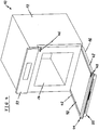
- FIG 4 illustrates a schematic perspective view of the cooking oven 10 according to the preferred embodiment of the present invention.
- the oven door 16 of the cooking oven 10 is open.
- the oven door 16 comprises a door frame including two door columns 42 and a top door frame part 44.
- the top door frame part 44 is removable.
- the cooking oven 10 comprises chassis contact elements 46 and door contact elements 48.
- the chassis contact elements 46 are arranged at a front frame enclosing the oven cavity 14.
- the door contact elements 48 are arranged at the door frame of the oven door 16. In this example, the door contact elements 48 are arranged at the top door frame part 44.
- the chassis contact elements 46 and the door contact elements 48 are in an electric contact to each other, when the oven door 16 is closed.
- the chassis contact elements 46 are arranged in the right upper corner of the front frame enclosing the oven cavity 14.
- the door contact elements 48 are arranged in the right upper corner of the door frame, when the oven door 16 is in the closed state.
- the chassis contact elements 46 and the door contact elements 48 provide electric contacts between the chassis 12 and the oven door 16, when the oven door 16 is in the closed state.
- a wireless electrical contact or a wireless connection the oven door 16 and the chassis 12 may be provided. This may be realized by wireless energy transfer and without any physical contacts for the transfer of electric current, for example by using inductive coupling between the door 16 and the chassis 12 of the domestic appliance 10.
- a primary coil may be arranged in the chassis 12 and a secondary coil may be part of the oven door 16. The coils are aligned in the operating position in such a way to each other, so that a very high inductive coupling between the primary and secondary coil results. If the door 16 removes from its operating and closed position, with increasing distance of the door 16 and/or increasing tilt angle between the coils, the wireless inductive coupling dissolves.
- additional signals may be transmitted between the oven door 16 and the chassis 12 as well.
- FIG 5 illustrates a schematic perspective view of an upper part of the oven door 16 for the cooking oven 10 according to the preferred embodiment of the present invention.
- the door handle 20 is attached at the outer glass panel 30 of the oven door 16.
- the handle adapters 26 are directly attached at the outer glass panel 30, while the handle bar 24 is attached at the handle adapters 26.
- the electric device 28 is arranged in the central portion of the handle bar 24.
- the electric device 28 includes a network interface unit 50, an LED display 40 and/or an LED indicator 40.
- the handle bar 24 is formed as a hollow profile part. At both ends of the handle bar 24 a plug element 52 is inserted in each case.
- a USB interface 54 is an integrated part of the handle adapter 26 on the left hand side.
- An antenna 56 is an integrated part of the handle adapter 26 on the right hand side.
- the USB interface 54 is a standard type.
- the USB interface 54 may also be arranged inside the housing 34.
- a WLAN stick may be plugged in the USB interface 54 for a data transmission.
- a personal computer may be connected via a USB cable and the USB interface 54 to a control unit of the cooking oven 10.
- this may be advantageous in a service case, because a function of appliance can be checked or a software update can be performed without disassembling the domestic appliance in order to obtain access to the control unit.
- the USB interface 54 may be placed on the top wall of the handle adapter 26, on its side walls, but also in the handle bar 24 as well.
- FIG 6 illustrates a schematic sectional side view of the door handle 20 attached at the oven door 16 of the cooking oven 10 according to the preferred embodiment of the present invention.
- the door handle 20 is attached at the outer glass panel 30 of the oven door 16, wherein the handle adapters 26 are directly attached at the outer glass panel 30, while the handle bar 24 is attached at the handle adapters 26.
- FIG 6 clarifies that the handle bar 24 is formed as the round hollow profile part.
- an inner space 62 is formed in the handle bar 24.
- the electric device 28 is arranged inside said inner space 62 of the handle bar 24 and in the housing 34.
- the electric device 28 includes a network interface unit 50, a WIFI unit 64 and a wiring connector element 66.
- the housing 34 allows the reception of the WIFI unit 64, which is usually bigger than the inner space 62 of the handle bar 24. Further, the housing 34 avoids a direct contact to the handle bar 24 made of metal. Moreover, the housing 34 insures an easy assembling.
- the housing 34 is made of plastic and protects sufficiently the WIFI unit 64 and other components of the electric device 28. Additionally, the housing 34 made of plastic provides an electric isolation for the electric device 28.
- the WIFI unit 64 with the antenna 56 may be placed into at least one of the handle adapter(s) 26, by which the handle bar 24 is fixed to the oven door 16 and/or in the housing 34 fixed to the handle bar 24.
- WIFI units 64 are available on the market as standard modules. The advantage of standard modules is that the ready developed WIFI unit 64 reduces the development effort and the costs.
- the antenna 56 may be placed in the handle adapter 26.
- the antenna 56 is chip or stripe type.
- data can be transmitted by means of a wiring or electric conductors to a WLAN module in the chassis 12.
- one antenna 56 with different characteristics may be placed as well.
- the both antennas 56 are connected by means of wiring which is going through the inner space 62 of the handle bar 24.
- the antenna 56 may be placed in a plastic housing arrangeable in each position of the door handle 20 as well.
- the housing 34 is fixed at the handle bar 24 by a housing screw 58.
- Said housing screw 58 penetrates a screw hole 84 in the housing 34 and a flow drill thread 60 formed in the handle bar 24.
- the flow drill screw technology insures a fixation of the housing screw 58 in the flow drill thread 60 with higher torque values, so that a strong fixation is ensured.
- the flow drill screw technology also simplifies the fixation on the hollow handle bar 24 without using any additional components or tools.
- the electric device 28 includes a touch sensor or a touch dimmer, then the flow drill screw technology ensures a reliable contact between said touch sensor or touch dimmer and the handle bar 24.
- FIG 7 illustrates a schematic exploded perspective view of the door handle 20 for the oven door 16 of the cooking oven 10 according to the preferred embodiment of the present invention.
- the handle bar 24 includes a recess 70 provided for receiving the housing 34.
- the housing 34 includes a clip element 68 for inserting into one face side of the recess 70.
- the housing 34 may be fastened by the housing screw 58, which is insertable into the flow drill thread 60 formed in the handle bar 24.
- the camera lens 38 is attached at the housing 34.
- the housing screw 58 is spaced from the wiring cables 72 and wiring connector elements 66 inside the handle bar 24.
- the handle adapter 26 includes a cable opening 74 at that side, which contacts the oven door 16, while the outer glass panel 30 includes at least one cable opening 88 at opposite.
- a wiring cable 72 extends between the recess 70 of the handle bar 24 on the one hand and the cable opening 74 of the handle adapter 26 and the cable opening 88 of the outer glass panel 30 on the other hand.
- Two wiring connector elements 66 are attached at the ends of the wiring cable 72.
- the wiring connector element 66 in the recess 70 of the handle bar 24 is provided for a connection to the electric device 28 in the housing 34.
- the wiring connector element 66 in the cable opening 74 of the handle adapter 26 provided for penetrating the opening 88, preferably formed as slot hole or hole, in the outer glass panel 30 and a connection behind said outer glass panel 30.
- the open ends of the handle bar 24 formed as the round hollow profile part are filled by the plug elements 52.
- the power supply from the chassis 12 of the domestic appliance 10 or cooking oven 10 to the door or oven door 16, respectively, may be provided by means of the wiring cable 72, by means of wireless inductive technology or by means of electric conductors, which are engaged, when the oven door 16 is closed and disengaged, when said oven door 16 is open.
- the flow drill technology allows the use of relative long screws in very thin walls.
- the use of the flow drill technology allows the very thin material for the handle bar 24, so that the hollow handle bar 24 provides enough inner space 62 for the wiring cables 72 and wiring connector elements 66 inside the handle bar 24.
- FIG 8 illustrates a schematic partial sectional perspective view of the upper part of the oven door 16 for the cooking oven 10 according to the preferred embodiment of the present invention.
- the handle adapters 26 are directly attached at the outer glass panel 30, while the handle bar 24 is attached at the handle adapters 26.
- a handle screw 76 penetrates the outer glass panel, the handle adapter 26 and a thread formed in the plug element 52. After fixing the door handle 20 at the outer glass panel 30, the wiring cable 72 and wiring connector element 66, which is coming out from a rear side of outer glass panel 30, can be connected to an electric connector of the oven door 16.
- another conduction system arranged inside the oven door 16 door can be directly connected to the wiring cable 72 of the door handle 20, for example by means of a plug-in connector element. This contributes also to a very easy exchangeability of the door handle 20.
- FIG 8 clarifies the course of the wiring cable 72 between the electric device 28 on the one hand and the cable opening 74 in the handle adapter 26 as well as the cable opening 88 in the outer glass panel 30 on the other hand.
- the wiring cable 72 from the electric device 28 in the handle bar 24 propagates through the inner space of the hollow profile part of said handle bar 24 up to the handle adapter 26, afterward through the cable opening 74 in the handle adapter 26 and at last through the cable opening 74 in the outer glass panel 30.
- the handle bar 24, the adapter 26, the housing 34, the electric device 28, the wiring cable 72 and wiring connector elements 66 can be preassembled together, and afterward of the door handle 20 is fixed on the outer glass panel 30 of the oven door 16.
- the outer glass panel may be provided with a bigger hole or slot, so that the handle screw 76 for the door handle 20 as well as the wiring cable 72 with the wiring connector element 66 can penetrate said hole or slot, respectively.
- FIG 9 illustrates two scaled up details of the partial sectional perspective view of the upper part of the oven door 16 shown in FIG 8 .
- the first scaled up detail on the left hand side shows the handle screw 76 penetrating the outer glass panel, the handle adapter 26 and the thread formed in the plug element 52.
- the wiring cable 72 penetrates the outer glass panel 30 behind the cable opening 74 in the handle adapter 26.
- the handle adapter 26 acts as a spacer between the handle bar 24 and the outer glass panel 30 of the oven door 16. At least one handle adapter 26 is required as spacer. Preferably, two handle adapters 26 are placed at either ends of the handle bar 24 in order to connect said handle bar 26 to the oven door 16.
- the handle screw 76 penetrates the handle adapters 26 and is fixed in the thread formed in the plug element 52 inserted into the handle bar 24, so that the handle bar 24 and the both handle adapters 26 are fixed by two handle screws 76 all in all.
- the handle adapter 26 can also be fixed to the handle bar 24 at first, and afterward the whole preassembled door handle 20 may be fixed at the oven door 16, e.g. at the outer glass panel 30 of said oven door 16.
- the second scaled up detail on the right hand side shows the electric device 28 partially inside the central portion of the handle bar 24 and partially inside the housing 34.
- the electric device 28 is the network interface unit 50 including the WIFI unit 64, the wiring connector element 66 and the camera 36.
- FIG 10 illustrates a schematic perspective view of the housing 34 for an electric device 28 attachable to the door handle 20 for the oven door 16 of the cooking oven 10 according to the preferred embodiment of the present invention.
- the electric device 28 is partially inside the housing 34.
- the electric device 28 is the network interface unit 50 including a printed circuit board.
- the circuit board of the network interface unit 50 is inserted in and supported by a circuit board guide 80.
- Said circuit board guide 80 is formed within the housing 34.
- the network interface unit 50 includes the WIFI unit 64, the wiring connector element 66, the LED display 40 and/or LED indicator, a light guide 86, the camera 36, a camera module 78 and a circuit board interface 82.
- the clip element 68 is formed at one side of the housing 34, while the screw hole 84 for receiving the housing screw 58 is formed on its opposite side.
- the housing screw 58 penetrates the screw hole 84 in the housing 34 and the flow drill thread 60 formed in the handle bar 24.
- the present invention relates to the door handle 20 for the oven door 16 of the cooking oven 10
- the present invention relates to a door handle for a door of an arbitrary domestic appliance.
Claims (15)
- Poignée de porte (20) pour une porte (16) d'un appareil domestique (10), en particulier pour une porte de four (16) d'un four de cuisson (10), dans laquelle- la poignée de porte (20) comprend une barre de poignée allongée (24) réalisée sous la forme d'une partie de profil creux ou d'un tuyau,"- la poignée de porte (20) comprend au moins un adaptateur de poignée (26), de préférence deux adaptateurs de poignée (26), pouvant être raccordés, ou étant raccordés, à la barre de poignée (24) au niveau de son côté avant et pouvant être raccordés à la porte (16) au niveau de son côté arrière,- la poignée de porte (20) comprend au moins un boîtier (34) fixé de manière amovible à la barre de poignée (24),- la barre de poignée (24) comprend au moins un évidement (70) pour recevoir au moins partiellement le boîtier (34),- le boîtier (34) comprend un côté ouvert faisant face à l'évidement (70) de la poignée de porte (20) de telle sorte qu'un espace interne (62) de la poignée de porte (20) soit agrandi par ledit boîtier (34),- la poignée de porte (20) comprend un dispositif électrique (28) disposé, ou pouvant être disposé, à l'intérieur du boîtier (34) et/ou à l'intérieur de la barre de poignée (24) à côté dudit boîtier (34),- l'adaptateur de poignée (26) comprend au moins une ouverture pour câble (74) au niveau de son côté arrière, et- la poignée de porte (20) comprend au moins un fil de câblage (72) s'étendant à l'intérieur de la barre de poignée entre le dispositif électrique (28) et l'ouverture pour câble (74) de l'adaptateur de poignée (26),caractérisée en ce que
au moins une antenne (56) et/ou une interface USB (54) sont disposées dans l'adaptateur de poignée (26) ou au niveau de ce dernier. - Poignée de porte selon la revendication 1,
caractérisée en ce que
la barre de poignée (24) est composée d'un métal, de préférence d'aluminium. - Poignée de porte selon la revendication 1 ou 2,
caractérisée en ce que
l'adaptateur de poignée (26) et/ou le boîtier (34) sont composés de matières plastiques. - Poignée de porte selon l'une quelconque des revendications précédentes,
caractérisée en ce que
le boîtier (34) peut être fixé au niveau de la barre de poignée (24) par au moins une vis de boîtier (58) et/ou au moins un élément d'attache (68), dans laquelle, de préférence, le boîtier (34) peut être fixé au niveau de la barre de poignée (24) par une vis de boîtier (58) et un élément d'attache (68). - Poignée de porte selon l'une quelconque des revendications précédentes,
caractérisée en ce que
la barre de poignée (24) comprend au moins un filetage de fluoperçage (60) pour recevoir la vis de boîtier (58) et/ou au moins une vis de poignée (74) . - Poignée de porte selon l'une quelconque des revendications précédentes,
caractérisée en ce que
le dispositif électrique (28) comprend au moins une unité d'interface réseau (50), dans laquelle, de préférence, ladite unité d'interface réseau (50) comprend une unité Wi-Fi (64), une unité Bluetooth, une unité iNFC et/ou une unité Zig Bee. - Poignée de porte selon l'une quelconque des revendications précédentes,
caractérisée en ce que
le dispositif électrique (28) comprend au moins une caméra (36), un objectif (38), un module de caméra (78), un dispositif d'affichage à DEL (40), un indicateur à DEL (40), un conduit de lumière (86), une antenne (56), un projecteur, un capteur et/ou une interface USB (54). - Poignée de porte selon l'une quelconque des revendications précédentes,
caractérisée en ce que
le fil de câblage (72) comprend un élément de connecteur de câblage (66) au niveau d'une extrémité ou deux éléments de connecteur de câblage (66) au niveau de deux extrémités, dans laquelle, de préférence, ledit élément de connecteur de câblage (66) est prévu pour être raccordé au dispositif électrique (28) et/ou pour être raccordé à un élément de connecteur de la porte (16) et/ou pour préparer une mise à la terre électrique de la barre de poignée (24) à un châssis (12) du four de cuisson (10) . - Poignée de porte selon l'une quelconque des revendications précédentes,
caractérisée en ce que
la barre de poignée (24) comprend au moins un élément enfichable (52), de préférence deux éléments enfichables (52), dans laquelle ledit élément enfichable (52) est prévu pour fermer une extrémité de la barre de poignée (24) ou dans laquelle ledit élément enfichable (52) est directement pressé dans une ouverture latérale de la poignée de porte (20). - Poignée de porte selon la revendication 9,
caractérisée en ce que
l'élément enfichable (52) comprend un filetage pour recevoir une vis de poignée (76) reliant la barre de poignée (24), l'adaptateur de poignée (26) et/ou la porte (16) ou un panneau avant (30) de ladite porte (16). - Poignée de porte selon l'une quelconque des revendications précédentes,
caractérisée en ce que
l'évidement (70) et le boîtier (34) sont disposés dans une partie centrale de la barre de poignée (24), dans laquelle, de préférence, ledit évidement (70) et ledit boîtier (34) peuvent être disposés entre la barre de poignée (24) et la porte (16). - Porte pour un appareil domestique, en particulier une porte de four (16) pour un four de cuisson (10), comprenant une poignée de porte fixée, ou pouvant être fixée, à ladite porte (16),
caractérisée en ce que
la porte (16) comprend une poignée de porte (20) selon l'une quelconque des revendications 1 à 11, dans laquelle, de préférence, l'objectif (38) est dirigé vers une fenêtre de porte (18) de la porte (18) de telle sorte qu'une cavité (14) derrière la porte (16) se trouve à l'intérieur d'un champ de vision dudit objectif (38). - Porte selon la revendication 12,
caractérisée en ce que
la porte (16) comporte des trous pour les vis de poignée (76) et au moins une ouverture pour câble (88), en particulier réalisée sous la forme d'un trou oblong, pour des fils de câblage (72), dans laquelle ladite ouverture pour câble (88) est à l'opposé de l'ouverture pour câble (74) de l'adaptateur de poignée (26) et dans laquelle, de préférence, la porte (16) comprend un panneau de verre externe (30) comprenant les trous pour les vis de poignée (76) et l'ouverture pour câble (88). - Appareil domestique, en particulier un four de cuisson (10),
comprenant une porte (16) et une poignée de porte fixée, ou pouvant être fixée, à ladite porte (16), caractérisé en ce que
l'appareil domestique (10) comprend une poignée de porte (20) selon l'une quelconque des revendications 1 à 11 et/ou une porte (16) selon la revendication 12 ou 13. - Appareil domestique selon la revendication 14,
caractérisé en ce que
l'appareil domestique (10) comprend des éléments de contact de châssis (46) et des éléments de contact de porte (48) qui sont en contact les uns avec les autres dans un état fermé de la porte (16), dans lequel, de préférence, un contact galvanique ou inductif se produit entre les éléments de contact de châssis (46) et les éléments de contact de porte (48) .
Priority Applications (5)
| Application Number | Priority Date | Filing Date | Title |
|---|---|---|---|
| EP15182703.7A EP3136002B1 (fr) | 2015-08-27 | 2015-08-27 | Poignée de porte pour une porte d'un appareil domestique |
| US15/741,801 US20180216830A1 (en) | 2015-08-27 | 2016-07-21 | Door handle for a door of a domestic appliance |
| BR112018001933A BR112018001933A2 (pt) | 2015-08-27 | 2016-07-21 | puxador de porta, porta para um aparelho doméstico e aparelho doméstico |
| AU2016311014A AU2016311014A1 (en) | 2015-08-27 | 2016-07-21 | Door handle for a door of a domestic appliance |
| PCT/EP2016/067360 WO2017032515A1 (fr) | 2015-08-27 | 2016-07-21 | Poignée de porte destinée à une porte d'appareil électroménager |
Applications Claiming Priority (1)
| Application Number | Priority Date | Filing Date | Title |
|---|---|---|---|
| EP15182703.7A EP3136002B1 (fr) | 2015-08-27 | 2015-08-27 | Poignée de porte pour une porte d'un appareil domestique |
Publications (2)
| Publication Number | Publication Date |
|---|---|
| EP3136002A1 EP3136002A1 (fr) | 2017-03-01 |
| EP3136002B1 true EP3136002B1 (fr) | 2019-07-03 |
Family
ID=54012060
Family Applications (1)
| Application Number | Title | Priority Date | Filing Date |
|---|---|---|---|
| EP15182703.7A Active EP3136002B1 (fr) | 2015-08-27 | 2015-08-27 | Poignée de porte pour une porte d'un appareil domestique |
Country Status (5)
| Country | Link |
|---|---|
| US (1) | US20180216830A1 (fr) |
| EP (1) | EP3136002B1 (fr) |
| AU (1) | AU2016311014A1 (fr) |
| BR (1) | BR112018001933A2 (fr) |
| WO (1) | WO2017032515A1 (fr) |
Cited By (1)
| Publication number | Priority date | Publication date | Assignee | Title |
|---|---|---|---|---|
| EP4023943A1 (fr) | 2020-12-31 | 2022-07-06 | Arçelik Anonim Sirketi | Dispositif de cuisson comprenant une poignée et son procédé d'assemblage |
Families Citing this family (21)
| Publication number | Priority date | Publication date | Assignee | Title |
|---|---|---|---|---|
| WO2016034295A1 (fr) * | 2014-09-03 | 2016-03-10 | Electrolux Appliances Aktiebolag | Appareil électroménager, en particulier four de cuisson, doté d'une caméra |
| US11104502B2 (en) * | 2016-03-01 | 2021-08-31 | Jeffrey S. Melcher | Multi-function compact appliance and methods for a food or item in a container with a container storage technology |
| DE102017202773A1 (de) * | 2017-02-21 | 2018-08-23 | BSH Hausgeräte GmbH | Gargerät mit einem entnehmbar ausgebildeten Sensormodul |
| DE102017004136A1 (de) * | 2017-05-01 | 2018-11-08 | BSH Hausgeräte GmbH | Haushaltsgerät mit Beleuchtungseinrichtung für Griffmulde |
| EP3665419A4 (fr) * | 2017-08-11 | 2021-05-05 | Brava Home, Inc. | Systèmes et procédés de cuisson configurables |
| EP3450853B1 (fr) * | 2017-08-28 | 2021-02-24 | Electrolux Appliances Aktiebolag | Four de cuisson avec un ensemble de caméra |
| US10747968B2 (en) | 2017-11-22 | 2020-08-18 | Jeffrey S. Melcher | Wireless device and selective user control and management of a wireless device and data |
| DE102017220888A1 (de) * | 2017-11-22 | 2019-05-23 | BSH Hausgeräte GmbH | Sensoreinheit zur Anordnung an einer Außenseite eines Haushaltsgeräts |
| WO2019197596A1 (fr) * | 2018-04-12 | 2019-10-17 | Electrolux Appliances Aktiebolag | Porte automatique pour appareil électroménager |
| PL236641B1 (pl) | 2018-08-29 | 2021-02-08 | Amica Spolka Akcyjna | Układ komunikacji pomiędzy drzwiami a korpusem piekarnika |
| PL236640B1 (pl) | 2018-08-29 | 2021-02-08 | Amica Spolka Akcyjna | Piekarnik z dotykowym uchwytem drzwi |
| US11650628B1 (en) | 2018-10-03 | 2023-05-16 | Anthony, Inc. | Display case door with touch screen |
| US11419434B1 (en) * | 2018-10-03 | 2022-08-23 | Anthony, Inc. | Display case door with door handle camera |
| US11006812B2 (en) | 2018-10-11 | 2021-05-18 | Haier Us Appliance Solutions, Inc. | Status indicator and lighting assembly for an appliance door |
| US11686032B2 (en) * | 2019-04-30 | 2023-06-27 | Whirlpool Corporation | User-interface system for a laundry appliance |
| DE102019206334A1 (de) * | 2019-05-03 | 2020-11-05 | BSH Hausgeräte GmbH | Haushaltsgerät mit Energieübertragungseinrichtung |
| DE102019134481A1 (de) * | 2019-12-16 | 2021-06-17 | Miele & Cie. Kg | Haushaltsgerät |
| JP7409890B2 (ja) | 2020-01-31 | 2024-01-09 | 東芝ライフスタイル株式会社 | 冷蔵庫 |
| EP3879182A1 (fr) | 2020-03-10 | 2021-09-15 | Electrolux Appliances Aktiebolag | Module de caméra |
| US11340853B2 (en) * | 2020-04-01 | 2022-05-24 | Anova Applied Electronics, Inc. | Appliance handle with automatic shutoff of input interface elements |
| PL438257A1 (pl) * | 2021-06-24 | 2022-12-27 | WALA Spółka z ograniczoną odpowiedzialnością | Uchwyt rurowy dla elementu zamykającego otwór obiektu z mechanizmem zaślepiającym dla cięgna sterującego |
Citations (1)
| Publication number | Priority date | Publication date | Assignee | Title |
|---|---|---|---|---|
| WO2010125786A1 (fr) * | 2009-04-27 | 2010-11-04 | パナソニック株式会社 | Dispositif de cuisson |
Family Cites Families (11)
| Publication number | Priority date | Publication date | Assignee | Title |
|---|---|---|---|---|
| AU1368297A (en) * | 1996-01-19 | 1997-08-11 | Aktiebolaget Electrolux | A control device for a domestic oven |
| CN2903851Y (zh) * | 2006-01-18 | 2007-05-23 | 海尔集团公司 | 带自照明功能的冰箱门把手 |
| ITPI20060070A1 (it) * | 2006-06-12 | 2007-12-13 | Studio Carlesi Design | Porta per forni di elettrodomestici |
| US20090039068A1 (en) * | 2007-08-10 | 2009-02-12 | Electrolux Home Products, Inc. | Electric current conduction system for appliance |
| KR101455861B1 (ko) * | 2008-02-21 | 2014-11-03 | 엘지전자 주식회사 | 냉장고 및 냉장고 도어 핸들 |
| DE102008041519B4 (de) * | 2008-08-25 | 2021-07-29 | BSH Hausgeräte GmbH | Türgriff für eine Tür eines Hausgeräts und Tür für ein Hausgerät |
| US20100154172A1 (en) * | 2008-12-22 | 2010-06-24 | Whirlpool Corporation | Handle with docking station |
| DE102009033087A1 (de) * | 2009-07-14 | 2011-02-10 | Liebherr-Werk Lienz Gmbh | Kühl- und/oder Gefriergerät |
| DE102010003898A1 (de) * | 2010-04-13 | 2011-11-17 | BSH Bosch und Siemens Hausgeräte GmbH | Türgriff für ein Hausgerät sowie Tür für ein Hausgerät mit einem derartigen Türgriff |
| US20120127696A1 (en) * | 2010-11-22 | 2012-05-24 | Visteon Global Technologies, Inc. | Signature lighting system for appliance |
| DE102011087753B4 (de) * | 2011-12-05 | 2021-11-11 | BSH Hausgeräte GmbH | Türgriff mit an einem Griffprofil angeschraubten Griffbock |
-
2015
- 2015-08-27 EP EP15182703.7A patent/EP3136002B1/fr active Active
-
2016
- 2016-07-21 AU AU2016311014A patent/AU2016311014A1/en not_active Abandoned
- 2016-07-21 US US15/741,801 patent/US20180216830A1/en not_active Abandoned
- 2016-07-21 WO PCT/EP2016/067360 patent/WO2017032515A1/fr active Application Filing
- 2016-07-21 BR BR112018001933A patent/BR112018001933A2/pt not_active Application Discontinuation
Patent Citations (1)
| Publication number | Priority date | Publication date | Assignee | Title |
|---|---|---|---|---|
| WO2010125786A1 (fr) * | 2009-04-27 | 2010-11-04 | パナソニック株式会社 | Dispositif de cuisson |
Cited By (1)
| Publication number | Priority date | Publication date | Assignee | Title |
|---|---|---|---|---|
| EP4023943A1 (fr) | 2020-12-31 | 2022-07-06 | Arçelik Anonim Sirketi | Dispositif de cuisson comprenant une poignée et son procédé d'assemblage |
Also Published As
| Publication number | Publication date |
|---|---|
| BR112018001933A2 (pt) | 2018-09-25 |
| US20180216830A1 (en) | 2018-08-02 |
| AU2016311014A1 (en) | 2018-01-18 |
| WO2017032515A1 (fr) | 2017-03-02 |
| EP3136002A1 (fr) | 2017-03-01 |
Similar Documents
| Publication | Publication Date | Title |
|---|---|---|
| EP3136002B1 (fr) | Poignée de porte pour une porte d'un appareil domestique | |
| US9176536B2 (en) | Wireless display for electronic devices | |
| CN103323920B (zh) | 紧凑型小型可插拔光模块 | |
| CN203688853U (zh) | 光纤连接器 | |
| AU2013267607B2 (en) | Thermal management of a communication transceiver in an electrical communication device | |
| KR20170123322A (ko) | 도어 모듈 및 그 사용 | |
| CN204652414U (zh) | 互联网安全网关装置 | |
| AU2015100773A4 (en) | Dual combined socket and wireless charging apparatus | |
| US8678862B2 (en) | Homeplug having panel replacement structure | |
| CN110249480B (zh) | 埋入型器具 | |
| US20120120612A1 (en) | Routing device for electronic device and method of assembling electronic device | |
| US20110111625A1 (en) | Connector for connecting external antenna | |
| EP3429035A1 (fr) | Fiche de cordon d'alimentation, câble, structure de cordon d'alimentation et dispositif électrique | |
| EP3462677A1 (fr) | Module de communication pour un appareil électroménager | |
| CN206817705U (zh) | 线控器及空调系统 | |
| US10423556B2 (en) | KVM extension device self-contained within a video connector | |
| EP4002060A1 (fr) | Cartouche d'ordinateur monocarte | |
| CN101630036B (zh) | 电子装置 | |
| RU2583999C1 (ru) | Датчик подключения для идентификации порта коммутационной панели | |
| US20130330947A1 (en) | Homeplug with changeable top case structure | |
| US8891238B2 (en) | Electronic device with detachable communication module | |
| CN106797111B (zh) | 接口单元 | |
| CN105030077A (zh) | 一种包含Z-Wave无线控制的电烤箱 | |
| CN215601602U (zh) | 遥控器 | |
| KR101605115B1 (ko) | 출입통제시스템의 통신랙용 쉘프 |
Legal Events
| Date | Code | Title | Description |
|---|---|---|---|
| PUAI | Public reference made under article 153(3) epc to a published international application that has entered the european phase |
Free format text: ORIGINAL CODE: 0009012 |
|
| STAA | Information on the status of an ep patent application or granted ep patent |
Free format text: STATUS: THE APPLICATION HAS BEEN PUBLISHED |
|
| AK | Designated contracting states |
Kind code of ref document: A1 Designated state(s): AL AT BE BG CH CY CZ DE DK EE ES FI FR GB GR HR HU IE IS IT LI LT LU LV MC MK MT NL NO PL PT RO RS SE SI SK SM TR |
|
| AX | Request for extension of the european patent |
Extension state: BA ME |
|
| STAA | Information on the status of an ep patent application or granted ep patent |
Free format text: STATUS: REQUEST FOR EXAMINATION WAS MADE |
|
| 17P | Request for examination filed |
Effective date: 20170901 |
|
| RBV | Designated contracting states (corrected) |
Designated state(s): AL AT BE BG CH CY CZ DE DK EE ES FI FR GB GR HR HU IE IS IT LI LT LU LV MC MK MT NL NO PL PT RO RS SE SI SK SM TR |
|
| GRAP | Despatch of communication of intention to grant a patent |
Free format text: ORIGINAL CODE: EPIDOSNIGR1 |
|
| STAA | Information on the status of an ep patent application or granted ep patent |
Free format text: STATUS: GRANT OF PATENT IS INTENDED |
|
| RIC1 | Information provided on ipc code assigned before grant |
Ipc: F25D 23/02 20060101ALI20180830BHEP Ipc: F24C 15/02 20060101ALI20180830BHEP Ipc: F24C 7/08 20060101AFI20180830BHEP Ipc: F25D 29/00 20060101ALI20180830BHEP |
|
| INTG | Intention to grant announced |
Effective date: 20180919 |
|
| GRAJ | Information related to disapproval of communication of intention to grant by the applicant or resumption of examination proceedings by the epo deleted |
Free format text: ORIGINAL CODE: EPIDOSDIGR1 |
|
| STAA | Information on the status of an ep patent application or granted ep patent |
Free format text: STATUS: REQUEST FOR EXAMINATION WAS MADE |
|
| GRAP | Despatch of communication of intention to grant a patent |
Free format text: ORIGINAL CODE: EPIDOSNIGR1 |
|
| STAA | Information on the status of an ep patent application or granted ep patent |
Free format text: STATUS: GRANT OF PATENT IS INTENDED |
|
| INTC | Intention to grant announced (deleted) | ||
| INTG | Intention to grant announced |
Effective date: 20190206 |
|
| GRAS | Grant fee paid |
Free format text: ORIGINAL CODE: EPIDOSNIGR3 |
|
| GRAA | (expected) grant |
Free format text: ORIGINAL CODE: 0009210 |
|
| STAA | Information on the status of an ep patent application or granted ep patent |
Free format text: STATUS: THE PATENT HAS BEEN GRANTED |
|
| AK | Designated contracting states |
Kind code of ref document: B1 Designated state(s): AL AT BE BG CH CY CZ DE DK EE ES FI FR GB GR HR HU IE IS IT LI LT LU LV MC MK MT NL NO PL PT RO RS SE SI SK SM TR |
|
| REG | Reference to a national code |
Ref country code: GB Ref legal event code: FG4D |
|
| REG | Reference to a national code |
Ref country code: CH Ref legal event code: EP Ref country code: AT Ref legal event code: REF Ref document number: 1151482 Country of ref document: AT Kind code of ref document: T Effective date: 20190715 |
|
| REG | Reference to a national code |
Ref country code: DE Ref legal event code: R096 Ref document number: 602015033023 Country of ref document: DE |
|
| REG | Reference to a national code |
Ref country code: IE Ref legal event code: FG4D |
|
| PGFP | Annual fee paid to national office [announced via postgrant information from national office to epo] |
Ref country code: DE Payment date: 20190830 Year of fee payment: 5 Ref country code: FR Payment date: 20190830 Year of fee payment: 5 |
|
| REG | Reference to a national code |
Ref country code: NL Ref legal event code: MP Effective date: 20190703 |
|
| REG | Reference to a national code |
Ref country code: LT Ref legal event code: MG4D |
|
| PGFP | Annual fee paid to national office [announced via postgrant information from national office to epo] |
Ref country code: GB Payment date: 20190830 Year of fee payment: 5 |
|
| REG | Reference to a national code |
Ref country code: AT Ref legal event code: MK05 Ref document number: 1151482 Country of ref document: AT Kind code of ref document: T Effective date: 20190703 |
|
| PG25 | Lapsed in a contracting state [announced via postgrant information from national office to epo] |
Ref country code: FI Free format text: LAPSE BECAUSE OF FAILURE TO SUBMIT A TRANSLATION OF THE DESCRIPTION OR TO PAY THE FEE WITHIN THE PRESCRIBED TIME-LIMIT Effective date: 20190703 Ref country code: CZ Free format text: LAPSE BECAUSE OF FAILURE TO SUBMIT A TRANSLATION OF THE DESCRIPTION OR TO PAY THE FEE WITHIN THE PRESCRIBED TIME-LIMIT Effective date: 20190703 Ref country code: AT Free format text: LAPSE BECAUSE OF FAILURE TO SUBMIT A TRANSLATION OF THE DESCRIPTION OR TO PAY THE FEE WITHIN THE PRESCRIBED TIME-LIMIT Effective date: 20190703 Ref country code: NO Free format text: LAPSE BECAUSE OF FAILURE TO SUBMIT A TRANSLATION OF THE DESCRIPTION OR TO PAY THE FEE WITHIN THE PRESCRIBED TIME-LIMIT Effective date: 20191003 Ref country code: NL Free format text: LAPSE BECAUSE OF FAILURE TO SUBMIT A TRANSLATION OF THE DESCRIPTION OR TO PAY THE FEE WITHIN THE PRESCRIBED TIME-LIMIT Effective date: 20190703 Ref country code: SE Free format text: LAPSE BECAUSE OF FAILURE TO SUBMIT A TRANSLATION OF THE DESCRIPTION OR TO PAY THE FEE WITHIN THE PRESCRIBED TIME-LIMIT Effective date: 20190703 Ref country code: PT Free format text: LAPSE BECAUSE OF FAILURE TO SUBMIT A TRANSLATION OF THE DESCRIPTION OR TO PAY THE FEE WITHIN THE PRESCRIBED TIME-LIMIT Effective date: 20191104 Ref country code: BG Free format text: LAPSE BECAUSE OF FAILURE TO SUBMIT A TRANSLATION OF THE DESCRIPTION OR TO PAY THE FEE WITHIN THE PRESCRIBED TIME-LIMIT Effective date: 20191003 Ref country code: LT Free format text: LAPSE BECAUSE OF FAILURE TO SUBMIT A TRANSLATION OF THE DESCRIPTION OR TO PAY THE FEE WITHIN THE PRESCRIBED TIME-LIMIT Effective date: 20190703 Ref country code: HR Free format text: LAPSE BECAUSE OF FAILURE TO SUBMIT A TRANSLATION OF THE DESCRIPTION OR TO PAY THE FEE WITHIN THE PRESCRIBED TIME-LIMIT Effective date: 20190703 |
|
| PG25 | Lapsed in a contracting state [announced via postgrant information from national office to epo] |
Ref country code: RS Free format text: LAPSE BECAUSE OF FAILURE TO SUBMIT A TRANSLATION OF THE DESCRIPTION OR TO PAY THE FEE WITHIN THE PRESCRIBED TIME-LIMIT Effective date: 20190703 Ref country code: IS Free format text: LAPSE BECAUSE OF FAILURE TO SUBMIT A TRANSLATION OF THE DESCRIPTION OR TO PAY THE FEE WITHIN THE PRESCRIBED TIME-LIMIT Effective date: 20191103 Ref country code: AL Free format text: LAPSE BECAUSE OF FAILURE TO SUBMIT A TRANSLATION OF THE DESCRIPTION OR TO PAY THE FEE WITHIN THE PRESCRIBED TIME-LIMIT Effective date: 20190703 Ref country code: ES Free format text: LAPSE BECAUSE OF FAILURE TO SUBMIT A TRANSLATION OF THE DESCRIPTION OR TO PAY THE FEE WITHIN THE PRESCRIBED TIME-LIMIT Effective date: 20190703 Ref country code: GR Free format text: LAPSE BECAUSE OF FAILURE TO SUBMIT A TRANSLATION OF THE DESCRIPTION OR TO PAY THE FEE WITHIN THE PRESCRIBED TIME-LIMIT Effective date: 20191004 Ref country code: LV Free format text: LAPSE BECAUSE OF FAILURE TO SUBMIT A TRANSLATION OF THE DESCRIPTION OR TO PAY THE FEE WITHIN THE PRESCRIBED TIME-LIMIT Effective date: 20190703 |
|
| PG25 | Lapsed in a contracting state [announced via postgrant information from national office to epo] |
Ref country code: TR Free format text: LAPSE BECAUSE OF FAILURE TO SUBMIT A TRANSLATION OF THE DESCRIPTION OR TO PAY THE FEE WITHIN THE PRESCRIBED TIME-LIMIT Effective date: 20190703 |
|
| PG25 | Lapsed in a contracting state [announced via postgrant information from national office to epo] |
Ref country code: EE Free format text: LAPSE BECAUSE OF FAILURE TO SUBMIT A TRANSLATION OF THE DESCRIPTION OR TO PAY THE FEE WITHIN THE PRESCRIBED TIME-LIMIT Effective date: 20190703 Ref country code: PL Free format text: LAPSE BECAUSE OF FAILURE TO SUBMIT A TRANSLATION OF THE DESCRIPTION OR TO PAY THE FEE WITHIN THE PRESCRIBED TIME-LIMIT Effective date: 20190703 Ref country code: DK Free format text: LAPSE BECAUSE OF FAILURE TO SUBMIT A TRANSLATION OF THE DESCRIPTION OR TO PAY THE FEE WITHIN THE PRESCRIBED TIME-LIMIT Effective date: 20190703 Ref country code: RO Free format text: LAPSE BECAUSE OF FAILURE TO SUBMIT A TRANSLATION OF THE DESCRIPTION OR TO PAY THE FEE WITHIN THE PRESCRIBED TIME-LIMIT Effective date: 20190703 |
|
| PG25 | Lapsed in a contracting state [announced via postgrant information from national office to epo] |
Ref country code: LU Free format text: LAPSE BECAUSE OF NON-PAYMENT OF DUE FEES Effective date: 20190827 Ref country code: SK Free format text: LAPSE BECAUSE OF FAILURE TO SUBMIT A TRANSLATION OF THE DESCRIPTION OR TO PAY THE FEE WITHIN THE PRESCRIBED TIME-LIMIT Effective date: 20190703 Ref country code: IS Free format text: LAPSE BECAUSE OF FAILURE TO SUBMIT A TRANSLATION OF THE DESCRIPTION OR TO PAY THE FEE WITHIN THE PRESCRIBED TIME-LIMIT Effective date: 20200224 Ref country code: SM Free format text: LAPSE BECAUSE OF FAILURE TO SUBMIT A TRANSLATION OF THE DESCRIPTION OR TO PAY THE FEE WITHIN THE PRESCRIBED TIME-LIMIT Effective date: 20190703 Ref country code: CH Free format text: LAPSE BECAUSE OF NON-PAYMENT OF DUE FEES Effective date: 20190831 Ref country code: LI Free format text: LAPSE BECAUSE OF NON-PAYMENT OF DUE FEES Effective date: 20190831 Ref country code: MC Free format text: LAPSE BECAUSE OF FAILURE TO SUBMIT A TRANSLATION OF THE DESCRIPTION OR TO PAY THE FEE WITHIN THE PRESCRIBED TIME-LIMIT Effective date: 20190703 |
|
| REG | Reference to a national code |
Ref country code: BE Ref legal event code: MM Effective date: 20190831 |
|
| REG | Reference to a national code |
Ref country code: DE Ref legal event code: R097 Ref document number: 602015033023 Country of ref document: DE |
|
| PLBE | No opposition filed within time limit |
Free format text: ORIGINAL CODE: 0009261 |
|
| STAA | Information on the status of an ep patent application or granted ep patent |
Free format text: STATUS: NO OPPOSITION FILED WITHIN TIME LIMIT |
|
| PG2D | Information on lapse in contracting state deleted |
Ref country code: IS |
|
| PG25 | Lapsed in a contracting state [announced via postgrant information from national office to epo] |
Ref country code: IE Free format text: LAPSE BECAUSE OF NON-PAYMENT OF DUE FEES Effective date: 20190827 |
|
| 26N | No opposition filed |
Effective date: 20200603 |
|
| PG25 | Lapsed in a contracting state [announced via postgrant information from national office to epo] |
Ref country code: SI Free format text: LAPSE BECAUSE OF FAILURE TO SUBMIT A TRANSLATION OF THE DESCRIPTION OR TO PAY THE FEE WITHIN THE PRESCRIBED TIME-LIMIT Effective date: 20190703 Ref country code: BE Free format text: LAPSE BECAUSE OF NON-PAYMENT OF DUE FEES Effective date: 20190831 |
|
| REG | Reference to a national code |
Ref country code: DE Ref legal event code: R119 Ref document number: 602015033023 Country of ref document: DE |
|
| GBPC | Gb: european patent ceased through non-payment of renewal fee |
Effective date: 20200827 |
|
| PG25 | Lapsed in a contracting state [announced via postgrant information from national office to epo] |
Ref country code: CY Free format text: LAPSE BECAUSE OF FAILURE TO SUBMIT A TRANSLATION OF THE DESCRIPTION OR TO PAY THE FEE WITHIN THE PRESCRIBED TIME-LIMIT Effective date: 20190703 |
|
| PG25 | Lapsed in a contracting state [announced via postgrant information from national office to epo] |
Ref country code: HU Free format text: LAPSE BECAUSE OF FAILURE TO SUBMIT A TRANSLATION OF THE DESCRIPTION OR TO PAY THE FEE WITHIN THE PRESCRIBED TIME-LIMIT; INVALID AB INITIO Effective date: 20150827 Ref country code: MT Free format text: LAPSE BECAUSE OF FAILURE TO SUBMIT A TRANSLATION OF THE DESCRIPTION OR TO PAY THE FEE WITHIN THE PRESCRIBED TIME-LIMIT Effective date: 20190703 Ref country code: DE Free format text: LAPSE BECAUSE OF NON-PAYMENT OF DUE FEES Effective date: 20210302 Ref country code: FR Free format text: LAPSE BECAUSE OF NON-PAYMENT OF DUE FEES Effective date: 20200831 |
|
| PG25 | Lapsed in a contracting state [announced via postgrant information from national office to epo] |
Ref country code: GB Free format text: LAPSE BECAUSE OF NON-PAYMENT OF DUE FEES Effective date: 20200827 |
|
| PG25 | Lapsed in a contracting state [announced via postgrant information from national office to epo] |
Ref country code: MK Free format text: LAPSE BECAUSE OF FAILURE TO SUBMIT A TRANSLATION OF THE DESCRIPTION OR TO PAY THE FEE WITHIN THE PRESCRIBED TIME-LIMIT Effective date: 20190703 |
|
| PGFP | Annual fee paid to national office [announced via postgrant information from national office to epo] |
Ref country code: IT Payment date: 20220825 Year of fee payment: 8 |
|
| P01 | Opt-out of the competence of the unified patent court (upc) registered |
Effective date: 20230625 |