EP3135876B1 - Dispositif de post-traitement de gaz d'echappement - Google Patents
Dispositif de post-traitement de gaz d'echappement Download PDFInfo
- Publication number
- EP3135876B1 EP3135876B1 EP16176827.0A EP16176827A EP3135876B1 EP 3135876 B1 EP3135876 B1 EP 3135876B1 EP 16176827 A EP16176827 A EP 16176827A EP 3135876 B1 EP3135876 B1 EP 3135876B1
- Authority
- EP
- European Patent Office
- Prior art keywords
- heat energy
- metering module
- energy storage
- heat
- storage medium
- Prior art date
- Legal status (The legal status is an assumption and is not a legal conclusion. Google has not performed a legal analysis and makes no representation as to the accuracy of the status listed.)
- Active
Links
Images


Classifications
-
- F—MECHANICAL ENGINEERING; LIGHTING; HEATING; WEAPONS; BLASTING
- F01—MACHINES OR ENGINES IN GENERAL; ENGINE PLANTS IN GENERAL; STEAM ENGINES
- F01N—GAS-FLOW SILENCERS OR EXHAUST APPARATUS FOR MACHINES OR ENGINES IN GENERAL; GAS-FLOW SILENCERS OR EXHAUST APPARATUS FOR INTERNAL COMBUSTION ENGINES
- F01N3/00—Exhaust or silencing apparatus having means for purifying, rendering innocuous, or otherwise treating exhaust
- F01N3/08—Exhaust or silencing apparatus having means for purifying, rendering innocuous, or otherwise treating exhaust for rendering innocuous
- F01N3/10—Exhaust or silencing apparatus having means for purifying, rendering innocuous, or otherwise treating exhaust for rendering innocuous by thermal or catalytic conversion of noxious components of exhaust
- F01N3/18—Exhaust or silencing apparatus having means for purifying, rendering innocuous, or otherwise treating exhaust for rendering innocuous by thermal or catalytic conversion of noxious components of exhaust characterised by methods of operation; Control
- F01N3/20—Exhaust or silencing apparatus having means for purifying, rendering innocuous, or otherwise treating exhaust for rendering innocuous by thermal or catalytic conversion of noxious components of exhaust characterised by methods of operation; Control specially adapted for catalytic conversion ; Methods of operation or control of catalytic converters
- F01N3/2066—Selective catalytic reduction [SCR]
- F01N3/208—Control of selective catalytic reduction [SCR], e.g. dosing of reducing agent
-
- F—MECHANICAL ENGINEERING; LIGHTING; HEATING; WEAPONS; BLASTING
- F01—MACHINES OR ENGINES IN GENERAL; ENGINE PLANTS IN GENERAL; STEAM ENGINES
- F01N—GAS-FLOW SILENCERS OR EXHAUST APPARATUS FOR MACHINES OR ENGINES IN GENERAL; GAS-FLOW SILENCERS OR EXHAUST APPARATUS FOR INTERNAL COMBUSTION ENGINES
- F01N2240/00—Combination or association of two or more different exhaust treating devices, or of at least one such device with an auxiliary device, not covered by indexing codes F01N2230/00 or F01N2250/00, one of the devices being
- F01N2240/10—Combination or association of two or more different exhaust treating devices, or of at least one such device with an auxiliary device, not covered by indexing codes F01N2230/00 or F01N2250/00, one of the devices being a heat accumulator
-
- F—MECHANICAL ENGINEERING; LIGHTING; HEATING; WEAPONS; BLASTING
- F01—MACHINES OR ENGINES IN GENERAL; ENGINE PLANTS IN GENERAL; STEAM ENGINES
- F01N—GAS-FLOW SILENCERS OR EXHAUST APPARATUS FOR MACHINES OR ENGINES IN GENERAL; GAS-FLOW SILENCERS OR EXHAUST APPARATUS FOR INTERNAL COMBUSTION ENGINES
- F01N2260/00—Exhaust treating devices having provisions not otherwise provided for
- F01N2260/02—Exhaust treating devices having provisions not otherwise provided for for cooling the device
- F01N2260/024—Exhaust treating devices having provisions not otherwise provided for for cooling the device using a liquid
-
- F—MECHANICAL ENGINEERING; LIGHTING; HEATING; WEAPONS; BLASTING
- F01—MACHINES OR ENGINES IN GENERAL; ENGINE PLANTS IN GENERAL; STEAM ENGINES
- F01N—GAS-FLOW SILENCERS OR EXHAUST APPARATUS FOR MACHINES OR ENGINES IN GENERAL; GAS-FLOW SILENCERS OR EXHAUST APPARATUS FOR INTERNAL COMBUSTION ENGINES
- F01N2260/00—Exhaust treating devices having provisions not otherwise provided for
- F01N2260/20—Exhaust treating devices having provisions not otherwise provided for for heat or sound protection, e.g. using a shield or specially shaped outer surface of exhaust device
-
- F—MECHANICAL ENGINEERING; LIGHTING; HEATING; WEAPONS; BLASTING
- F01—MACHINES OR ENGINES IN GENERAL; ENGINE PLANTS IN GENERAL; STEAM ENGINES
- F01N—GAS-FLOW SILENCERS OR EXHAUST APPARATUS FOR MACHINES OR ENGINES IN GENERAL; GAS-FLOW SILENCERS OR EXHAUST APPARATUS FOR INTERNAL COMBUSTION ENGINES
- F01N2590/00—Exhaust or silencing apparatus adapted to particular use, e.g. for military applications, airplanes, submarines
- F01N2590/08—Exhaust or silencing apparatus adapted to particular use, e.g. for military applications, airplanes, submarines for heavy duty applications, e.g. trucks, buses, tractors, locomotives
-
- F—MECHANICAL ENGINEERING; LIGHTING; HEATING; WEAPONS; BLASTING
- F01—MACHINES OR ENGINES IN GENERAL; ENGINE PLANTS IN GENERAL; STEAM ENGINES
- F01N—GAS-FLOW SILENCERS OR EXHAUST APPARATUS FOR MACHINES OR ENGINES IN GENERAL; GAS-FLOW SILENCERS OR EXHAUST APPARATUS FOR INTERNAL COMBUSTION ENGINES
- F01N2610/00—Adding substances to exhaust gases
- F01N2610/02—Adding substances to exhaust gases the substance being ammonia or urea
-
- F—MECHANICAL ENGINEERING; LIGHTING; HEATING; WEAPONS; BLASTING
- F01—MACHINES OR ENGINES IN GENERAL; ENGINE PLANTS IN GENERAL; STEAM ENGINES
- F01N—GAS-FLOW SILENCERS OR EXHAUST APPARATUS FOR MACHINES OR ENGINES IN GENERAL; GAS-FLOW SILENCERS OR EXHAUST APPARATUS FOR INTERNAL COMBUSTION ENGINES
- F01N2610/00—Adding substances to exhaust gases
- F01N2610/03—Adding substances to exhaust gases the substance being hydrocarbons, e.g. engine fuel
-
- F—MECHANICAL ENGINEERING; LIGHTING; HEATING; WEAPONS; BLASTING
- F01—MACHINES OR ENGINES IN GENERAL; ENGINE PLANTS IN GENERAL; STEAM ENGINES
- F01N—GAS-FLOW SILENCERS OR EXHAUST APPARATUS FOR MACHINES OR ENGINES IN GENERAL; GAS-FLOW SILENCERS OR EXHAUST APPARATUS FOR INTERNAL COMBUSTION ENGINES
- F01N2610/00—Adding substances to exhaust gases
- F01N2610/11—Adding substances to exhaust gases the substance or part of the dosing system being cooled
-
- Y—GENERAL TAGGING OF NEW TECHNOLOGICAL DEVELOPMENTS; GENERAL TAGGING OF CROSS-SECTIONAL TECHNOLOGIES SPANNING OVER SEVERAL SECTIONS OF THE IPC; TECHNICAL SUBJECTS COVERED BY FORMER USPC CROSS-REFERENCE ART COLLECTIONS [XRACs] AND DIGESTS
- Y02—TECHNOLOGIES OR APPLICATIONS FOR MITIGATION OR ADAPTATION AGAINST CLIMATE CHANGE
- Y02A—TECHNOLOGIES FOR ADAPTATION TO CLIMATE CHANGE
- Y02A50/00—TECHNOLOGIES FOR ADAPTATION TO CLIMATE CHANGE in human health protection, e.g. against extreme weather
- Y02A50/20—Air quality improvement or preservation, e.g. vehicle emission control or emission reduction by using catalytic converters
-
- Y—GENERAL TAGGING OF NEW TECHNOLOGICAL DEVELOPMENTS; GENERAL TAGGING OF CROSS-SECTIONAL TECHNOLOGIES SPANNING OVER SEVERAL SECTIONS OF THE IPC; TECHNICAL SUBJECTS COVERED BY FORMER USPC CROSS-REFERENCE ART COLLECTIONS [XRACs] AND DIGESTS
- Y02—TECHNOLOGIES OR APPLICATIONS FOR MITIGATION OR ADAPTATION AGAINST CLIMATE CHANGE
- Y02T—CLIMATE CHANGE MITIGATION TECHNOLOGIES RELATED TO TRANSPORTATION
- Y02T10/00—Road transport of goods or passengers
- Y02T10/10—Internal combustion engine [ICE] based vehicles
- Y02T10/12—Improving ICE efficiencies
Definitions
- the invention relates to a device for exhaust gas aftertreatment for a vehicle, in particular an agricultural working machine, according to the preamble of claim 1.
- Agricultural work machines such as tractors or self-propelled harvesters, are typically equipped with an internal combustion engine that provides power to the drive and other functions.
- a combustion engine a diesel engine is usually used, the fuel is carried in one or more fuel tanks on the machine.
- the exhaust gases of the internal combustion engine contain different pollutants, so that in modern work machines, the exhaust gases are cleaned by a device for exhaust aftertreatment.
- the concentration of nitrogen oxides contained in the exhaust gases is reduced by selective catalytic reduction (SCR).
- the exhaust gas is an immediately reducing substance, for example ammonia or a precursor thereof, supplied, which releases the required reducing substances only in the exhaust gas.
- a precursor for example, a urea-water solution can be used.
- Ammonia is converted to molecular nitrogen and water by selective catalytic reduction with nitrogen monoxide and nitrogen dioxide.
- the selective catalytic reduction takes place in a so-called SCR catalyst.
- the injection nozzle is usually electrically actuated for metering the injected reducing agent.
- An injection of the reducing agent into the exhaust gas flow takes place upstream of the SCR catalyst.
- a cooling of the metering module is disclosed by means of cooling water, wherein the cooling water is passed via pipes from a cooling system to the metering and out of this.
- the lines are formed serpentine.
- Cooling water-based systems for cooling a dosing module are off US 2014 017 4696 A1 and US 2014 032 2088 A1 known, wherein in the cooling water circuit, an additional tank is provided in the inlet or return of the cooling water, which serves as a coolant reservoir.
- a thermal energy store means a component which is thermally conductively connected to the metering module, and in particular to the injection nozzle of the metering module, in order to absorb and store heat energy from the metering module and the injection nozzle.
- the heat energy store can be a component which is provided in addition to the components that ensure the function of the dosing module.
- the heat energy can be conducted from the dosing module to the heat energy store and, unlike a heat sink, stored there and not released to the environment through, for example, an enlarged surface.
- the thermal energy storage is configured and designed such that a sufficiently large amount of heat energy can be absorbed and stored by the metering module in order to avoid overheating of the metering module, in particular in the event of a sudden shutdown and interruption of the cooling of the metering module.
- the thermal energy store is arranged at a distance from or directly on the dosing module and / or the injection nozzle.
- a transport of the heat energy from the metering module and / or the injection nozzle to the heat energy storage by direct contact and / or via a heat conduction.
- An immediate arrangement of the thermal energy storage device on the metering module and / or the injection nozzle has the advantage that a rapid dissipation of the heat energy from the metering module and / or the injection nozzle is made possible to the thermal energy storage, whereby a strong increase in temperature at the metering module and / or the injection nozzle can be avoided.
- the heat energy storage on at least one storage medium in the form of a liquid or a solid for receiving the heat energy of the dosing is the material of the thermal energy storage, which serves to store the vast amount of heat energy in the heat energy storage.
- a heat energy store with a storage medium in the form of a solid may be formed, for example, as a one-piece body.
- a heat energy store with a storage medium in the form of a liquid can be designed, for example, to form a container for holding the liquid storage medium.
- a solid storage medium may be, for example, a metal such as copper, iron, or magnesium.
- a thermal energy storage device with a solid storage medium may, for example, be in the form of a metal component within the engine compartment, such as a support structure.
- a liquid storage medium may be, for example, water, which has a very high specific heat capacity.
- a heat energy store with a liquid storage medium can be arranged substantially above the metering module and / or the injection nozzle. This has the advantage that in a liquid storage medium in addition to the heat conduction, a natural, thermal convection, for example, within the liquid storage medium, can be made possible.
- the thermal energy store can thereby be designed, at least in part, for the rapid transfer of heat energy to a storage medium with high specific heat capacity and high storage capacity. Thereby, a recording and storage of heat energy of the metering module can be accelerated.
- At least a first and a second storage medium are provided, wherein the storage media may be solid and / or liquid and may have the same or different specific heat capacities.
- the heat energy store can have a plurality of storage media, for example with different specific heat capacities, whereby, for example, a solid storage medium with a low specific heat capacity, such as copper, promotes a dissipation of the heat energy from the dosing module to, for example, a liquid storage medium with a high specific heat capacity can.
- This can be a fast Derivation of the heat energy done by the dosing and a high amount of heat are absorbed in the heat energy storage
- the thermal energy store for receiving a liquid storage medium in the form of a tank and / or in the form of a pipeline is formed.
- a pipe is in the context of the invention, a hose to understand, as this is the recording of the liquid storage medium in the foreground.
- a thermal energy store for a liquid storage medium in the form of a tank can be arranged directly or at a distance from the dosing module and / or the injection nozzle.
- a spaced apart from the dosing module and / or the injection nozzle heat energy storage with a liquid storage medium can be fluid-permeable connected via pipes with the dosing.
- the pipelines can have a diameter which allows a natural thermal convection, that is to say a material movement of the liquid storage medium within the tank and / or the pipelines caused by the absorbed thermal energy
- the heat accumulator and / or the metering module, and in particular the injection nozzle are water-cooled.
- a water cooling of the dosing of the thermal energy storage and / or the injection nozzle can be done, for example, with an active cooling circuit, which is operated by a pump.
- the cooling of the thermal energy storage can be done in a solid storage medium by direct contact with the cooling water.
- cooling of the thermal energy store can take place, for example, by exchanging the liquid storage medium. This has the advantage that not only a rapid absorption of the heat energy is made possible by the dosing, but also a very large storage capacity can be ensured of thermal energy by replacing the liquid storage medium.
- the liquid storage medium is cooling water of the internal combustion engine.
- a thermal energy storage, the liquid storage medium is cooling water of the internal combustion engine can be connected to the cooling circuit of the engine so that cooling of the heat energy storage and / or the metering can be done by at least a partial flow of the cooling circuit of the engine. This allows active cooling of the thermal energy storage when the engine cooling circuit is running, thereby avoiding the storage of thermal energy in the thermal energy storage during normal operation of the vehicle, particularly the agricultural machine.
- the cooling water within the heat energy storage can be regarded as quasi-stationary.
- a thermal energy storage having two liquid storage media may be connected to the cooling water circuit such that a first liquid storage medium is disposed upstream of the metering module in the refrigerant circuit, and a second liquid storage medium is disposed downstream of the metering module.
- first the cooling water can exchange the first liquid storage medium, flow through the dosing module, and exchange the second liquid storage medium.
- both the first storage medium and the second storage medium via the cooling water heat conductively connected to the metering module and / or the injector for receiving and storing heat energy.
- the thermal energy store has cooling structures for emitting absorbed thermal energy.
- These cooling structures may be designed, for example, in the form of a profiling which is attached to the heat energy store on the outside, and serve for removing and discharging heat energy from the heat energy store and thereby acting as a heat sink. This has the advantage that the heat energy storage after receiving the heat energy from the dosing this can deliver faster to the environment.
- the thermal energy store has at least one heat protection device, which reduces a recording of thermal energy other than that of the dosing module.
- the thermal protection device reduces the absorption of heat energy from other components of the vehicle, such as the internal combustion engine and / or the exhaust line, which can be transmitted, for example in the form of heat radiation to the thermal energy storage. Thereby, the heating of the thermal energy storage can be reduced, whereby a higher heat energy from the dosing and / or the injection nozzle can be taken.
- the heat protection device can be designed, for example, in the form of an insulation, for example of a material of low thermal conductivity. It is also conceivable that the heat protection device is designed in the form of a heat shield against radiant heat, wherein the heat shield can be arranged spaced from the heat energy storage.
- the invention further relates to a vehicle, in particular an agricultural work machine, with at least one device for exhaust aftertreatment, which is off and on as above.
- FIG. 1 a vehicle 10 in the form of a tractor in the form of a tractor is shown in a schematic view from the side.
- the tractor 10 has an internal combustion engine 12 which, in a manner known per se and therefore not to be explained further, serves to drive the tractor 10.
- the internal combustion engine 12 can be used in a manner known per se for driving working and auxiliary equipment, such as working hydraulics or pneumatics, of the tractor 10.
- exhaust gases are produced, which are discharged via an exhaust pipe 14 through a device for exhaust aftertreatment 16 and an exhaust pipe 20 arranged substantially vertically in front of a driver's cab 18 to the environment.
- the exhaust aftertreatment device 16 has a catalyst 22 for reducing the concentration of nitrogen oxides contained in the exhaust gases by selective catalytic reduction (SCR).
- SCR selective catalytic reduction
- a reducing substance for example ammonia or a corresponding precursor, is fed to the exhaust gas flow upstream of the catalytic converter 22.
- the dosage of the excipient in the exhaust stream is carried out via a metering module 24, which has an injection nozzle 26 for injecting the excipient in the exhaust stream.
- the injection nozzle is electrically actuated for metering the injected reducing agent or amount of reducing agent, wherein the selective catalytic reduction takes place in the catalyst.
- the metering module 24 and the injection nozzle 26 are exposed to the heat radiation of the internal combustion engine and the exhaust line, so that the metering module 24 and the injector 26 are water cooled to avoid overheating during operation of the internal combustion engine 12, wherein a cooling of the metering module 24 and the injector 26th For example, via a partial flow of the cooling system (not shown) of the internal combustion engine 12 can be carried out.
- a heat energy storage 28 adjacent and thermally conductive to the metering module 24 and the injection nozzle 26 is arranged.
- the heat energy emitted by the internal combustion engine 12 and / or the exhaust gas line, in particular the catalytic converter 22, overheats the dosing module 24 and / or the injector 26 lead, which can lead to malfunction or even failure of the metering module 24 and / or the injector 26.
- heat energy from the dosing module 24 and / or the injector 26 can be transferred by heat conduction to the heat energy storage 28 and absorbed by this, the heat energy storage 28 in contrast to a Heat sink stores the absorbed heat energy from the dosing module 24.
- the thermal energy storage 28, which is disposed within the engine compartment of the tractor 10, has the advantage over a heat sink that the heat energy can be absorbed and stored, whereas a heat sink due to its geometric shape and a material of high thermal conductivity rather absorb the heat of the engine compartment and in addition to the dosing module 24 and / or the injection nozzle 26 would be transmitted.
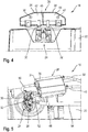
- FIG. 2 a heat energy store 28 arranged directly on the water-cooled dosing module 24 is shown.
- the dosing module 24 and the injection nozzle 26 are cooled by a partial flow of the coolant circuit of the internal combustion engine 12 during operation of the internal combustion engine 12.
- the coolant is introduced via an inlet nozzle 30 in the dosing module 24, and fed via a return pipe 32 back to the cooling circuit (not shown).
- the illustrated thermal energy storage 28 is integrated in the cooling circuit of the internal combustion engine, and is directly on the metering module 24, in particular the inlet pipe 30 and the return pipe 32, arranged.
- the thermal energy storage 28 is in the form of a tank for receiving liquid storage media, and has a first chamber 34 and a second chamber 36 each for receiving a liquid storage medium.
- the first chamber 34 is fluid-permeable directly connected to the inlet nozzle 30, 10 via the or an inlet 38 of the coolant circuit of the tractor can flow coolant into the first chamber 34 and from there into the inlet nozzle 30.
- the return pipe 32 of the dosing 24 is also fluidly connected directly to the second chamber 36 of the thermal energy storage 28, so that the coolant from the return pipe 32 through the second chamber 36 in a return line 40 which is fluidly connected to the second chamber 36 in the Cooling circuit of the vehicle or the tractor 10 can flow back.
- the thermal energy storage 28 on the metering module 24 in particular the inlet nozzle 30 and the return pipe 32, in a failure of the or the cooling pump and the coolant flow and / or a shutdown of the engine 12, the heat of the dosing 24 directly by the heat energy Memory 28 are received via the inlet nozzle 30 and the return pipe 32.
- the heat energy of the metering module 24 can be absorbed and stored by the liquid storage media in the first chamber 34 and the second chamber 36 of the thermal energy storage 28.
- the thermal energy store 28 is arranged substantially above the metering module 24 and the injection nozzle 26.
- natural thermal convection as a heat transfer mechanism can be effected within the first chamber 34 and the second chamber 36, respectively.
- the heated at the respective nozzle 30, 32 and heat energy absorbing storage medium within the first and / or second chamber 34, 36 rise, whereby cooler memory liquid storage medium can flow to the nozzle 30, 32.
- the absorption of heat energy from the metering module 24 can be improved by the heat energy storage 28, whereby overheating of the metering module 24 and in particular of the injection nozzle 26 can be avoided.
- FIG. 3 the heat energy store 28 arranged directly above the dosing module 24 is shown in a sectional view. It can be seen that the inlet nozzle 30 protrudes into the first chamber 34 with the first liquid storage medium 42, whereby a good transfer of heat energy from the Dosing module 24 can be ensured to the heat energy storage 28.
- the return pipe 32 of the metering module 24 hooks into the second chamber 36 of the thermal energy storage device 28, in which the second storage medium 44, in the form of water, in particular cooling water, is arranged.
- the first chamber 34 and the second chamber 36 of the thermal energy storage 28 are separated from each other by a partition wall 46 and each have an elongated extent.
- the heat energy storage 28 can be adapted to the respective available space within the engine compartment of the tractor 10, wherein ( FIG. 4 ) above the inlet stub 30 and the return stub 32 within the first chamber 34 and the second chamber 36, sufficient space should be provided for allowing natural thermal convection within the first and / or second chambers 34, 36.
- the coolant is passed through the inlet 38 into the first chamber 34 of the thermal energy storage 28, wherein the coolant within the first chamber 34 is the first storage medium 42.
- the coolant is passed from the first chamber 34 through the inlet port 30 for cooling the metering module 24 therethrough and leaves the metering module 24 via the return pipe 32 and enters the second chamber 36 of the thermal energy storage 28.
- the coolant in particular the cooling water, the second storage medium 44, until it is fed via the return line 40 back into the coolant circuit of the tractor 10.
- the second storage medium 44 is disposed with active cooling of the dosing 24 downstream of the dosing module 24, the second storage medium 44 has a higher temperature than the first storage medium 42, whereby the amount of storable heat energy of the second storage medium relative to the first storage medium 42nd something is reduced.
- the cooling water in the chambers 34, 36 forms the first storage medium 42 and the second storage medium 44th
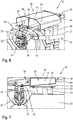
- the heat energy storage 28 is spaced and arranged above the dosing module 24.
- the dosing module 24 is arranged on a support module 48 above the catalyst 22, and thermally conductive, in particular fluid-permeable, connected to the metering module 24.
- the first chamber 34 of the thermal energy store 28 is connected via a feed line 50 to the inlet nozzle 30 of the metering module 24.
- the return pipe 32 of the metering module 24 is connected via a return line 52 to the second chamber 36 of the thermal energy storage 28.
- the injection nozzle 26 of the dosing module 24 is connected via an auxiliary conduit 54 to a reservoir of the auxiliary, not shown.
- the heat energy is conducted by the dosing module 24 (FIG. FIG. 6 ) via the inlet nozzle 30 and the return pipe 32 via the supply line 50 and the return line 52 to the first and the second chamber of the thermal energy storage 28, so that the heat energy of the dosing 24 by the first storage medium 42 and the second storage medium 44 can be recorded and stored ,
- the spaced arrangement of the thermal energy storage 28 to the metering module 24 and the injection nozzle 26 has the advantage that the thermal energy storage can be arranged in a space technically more favorable place within the engine compartment.
- the heat energy storage 28 is shown in a sectional side view, wherein between the heat energy storage 28 and the support module 48, a plate-shaped heat protection device 56 is arranged, which is in the form of a heat shield and the heat energy storage 28 protects against the radiation emitted by the catalyst 22 radiant heat. Thereby, absorption of heat energy from the catalyst 22 can be avoided, so that a higher amount of heat energy can be absorbed by the dosing module 24.
- the cut heat energy storage 28 shown has a substantially trapezoidal or substantially trapezoidal cross-section, wherein the catalyst 22 facing the bottom 58 is formed inclined or is formed inclined to form a slope.
- the gradient is formed by the inlet 38 and the return (not shown) to the metering module 24, so that even if damage to the inlet 38 and / or the return (not shown), a sufficiently large amount of storage medium, in particular cooling water, in the heat energy storage 28 for receiving heat energy of the dosing 24 is available.
- the heat protection device 56 is formed integrally with the support module 48.
- the thermal energy storage 28 is in this case with fastening means 60 detachably connected to the support module 48, and in particular the heat protection device 56
Landscapes
- Chemical & Material Sciences (AREA)
- Engineering & Computer Science (AREA)
- Chemical Kinetics & Catalysis (AREA)
- Health & Medical Sciences (AREA)
- Toxicology (AREA)
- Combustion & Propulsion (AREA)
- Mechanical Engineering (AREA)
- General Engineering & Computer Science (AREA)
- Exhaust Gas After Treatment (AREA)
Claims (9)
- Dispositif (16) de post-traitement des gaz d'échappement pour un véhicule (10), en particulier une machine de travail agricole, comprenant un moteur à combustion interne (12), comprenant un module de dosage (24) avec un injecteur (26) pour introduire un agent auxiliaire, en particulier un moyen réducteur comme de l'urée, dans le courant de gaz d'échappement du moteur à combustion interne (12), comprenant un accumulateur d'énergie thermique (28) qui est destiné à accumuler de l'énergie thermique du module de dosage (24) et est relié de manière thermoconductrice au module de dosage (24) et, en particulier, à l'injecteur (26), caractérisé en ce que l'accumulateur d'énergie thermique (28) est conçu, dans le but de recevoir des agents d'accumulation liquides (42, 44), sous la forme d'un réservoir qui comporte une première chambre (34) et une seconde chambre (36) pour recevoir chacune un agent d'accumulation liquide (42, 44), les agents d'accumulation liquides (42, 44) étant de l'eau de refroidissement du moteur à combustion interne (12), et l'eau de refroidissement étant conduite à partir de la première chambre (34) par l'intermédiaire d'une tubulure d'amenée (30) pour refroidir le module de dosage (24) en le traversant, et quittant le module de dosage (24) par l'intermédiaire d'une tubulure de retour (32) et pénétrant dans la seconde chambre (36) de l'accumulateur d'énergie thermique (28).
- Dispositif selon la revendication 1, caractérisé en ce que l'accumulateur d'énergie thermique (28) est disposé à distance de ou directement sur le module de dosage (24) et/ou sur l'injecteur (26).
- Dispositif selon la revendication 1 ou 2, caractérisé en ce que l'accumulateur d'énergie thermique (28) comporte au moins un agent d'accumulation (42, 44) en forme d'un liquide ou d'un solide pour absorber l'énergie thermique du module de dosage (24).
- Dispositif selon une des revendications précédentes, caractérisé en ce qu'au moins un premier et un second agent d'accumulation (42, 44) sont prévus, les agents d'accumulation (42, 44) pouvant être solides et/ou liquides et pouvant présenter des capacités thermiques spécifiques identiques ou différentes.
- Dispositif selon une des revendications précédentes, caractérisé en ce que l'accumulateur d'énergie thermique (28) pour recevoir un agent d'accumulation liquide (42, 44) est conçu en forme de conduite tubulaire.
- Dispositif selon une des revendications précédentes, caractérisé en ce que l'accumulateur d'énergie thermique et/ou le module de dosage, et en particulier l'injecteur, est refroidi par eau.
- Dispositif selon une des revendications précédentes, caractérisé en ce que l'accumulateur d'énergie thermique (28) comporte des structures de refroidissement pour céder de l'énergie thermique absorbée.
- Dispositif selon une des revendications précédentes, caractérisé en ce que l'accumulateur d'énergie thermique (28) comporte au moins un dispositif d'isolation thermique (56) qui réduit une absorption d'énergie thermique autre que celle du module de dosage (24).
- Véhicule, en particulier machine de travail agricole, comprenant au moins un dispositif (16) de post-traitement des gaz d'échappement selon une des revendications précédentes.
Applications Claiming Priority (1)
| Application Number | Priority Date | Filing Date | Title |
|---|---|---|---|
| DE102015114081.0A DE102015114081A1 (de) | 2015-08-25 | 2015-08-25 | Vorrichtung zur Abgasnachbehandlung |
Publications (2)
| Publication Number | Publication Date |
|---|---|
| EP3135876A1 EP3135876A1 (fr) | 2017-03-01 |
| EP3135876B1 true EP3135876B1 (fr) | 2018-03-14 |
Family
ID=56289416
Family Applications (1)
| Application Number | Title | Priority Date | Filing Date |
|---|---|---|---|
| EP16176827.0A Active EP3135876B1 (fr) | 2015-08-25 | 2016-06-29 | Dispositif de post-traitement de gaz d'echappement |
Country Status (2)
| Country | Link |
|---|---|
| EP (1) | EP3135876B1 (fr) |
| DE (1) | DE102015114081A1 (fr) |
Families Citing this family (1)
| Publication number | Priority date | Publication date | Assignee | Title |
|---|---|---|---|---|
| JP7448755B2 (ja) * | 2021-03-18 | 2024-03-13 | 株式会社クボタ | 排気処理装置の支持構造および排気処理装置付きエンジン |
Citations (1)
| Publication number | Priority date | Publication date | Assignee | Title |
|---|---|---|---|---|
| US20140290222A1 (en) * | 2013-03-15 | 2014-10-02 | Komatsu Ltd. | Exhaust gas post-treatment unit and construction vehicle carrying same |
Family Cites Families (5)
| Publication number | Priority date | Publication date | Assignee | Title |
|---|---|---|---|---|
| DE102007013524A1 (de) | 2007-03-21 | 2008-09-25 | Robert Bosch Gmbh | Dosiermodul mit verbesserten akustischen Eigenschaften |
| DE102012015768A1 (de) * | 2012-08-09 | 2013-03-07 | Daimler Ag | Kühlanordnung zum Kühlen eines Auslasses einer Dosiereinrichtung |
| US9103600B2 (en) * | 2012-12-21 | 2015-08-11 | Caterpillar Inc. | Injector cooling apparatus and method |
| US9091193B2 (en) * | 2013-12-13 | 2015-07-28 | Cnh Industrial America Llc | Systems and methods for cooling a diesel exhaust fluid dosing module of an agricultural vehicle |
| US20140322088A1 (en) * | 2014-07-10 | 2014-10-30 | Perkins Engines Company Limited | Auxiliary coolant tank for exhaust aftertreatment system |
-
2015
- 2015-08-25 DE DE102015114081.0A patent/DE102015114081A1/de not_active Withdrawn
-
2016
- 2016-06-29 EP EP16176827.0A patent/EP3135876B1/fr active Active
Patent Citations (1)
| Publication number | Priority date | Publication date | Assignee | Title |
|---|---|---|---|---|
| US20140290222A1 (en) * | 2013-03-15 | 2014-10-02 | Komatsu Ltd. | Exhaust gas post-treatment unit and construction vehicle carrying same |
Also Published As
| Publication number | Publication date |
|---|---|
| DE102015114081A1 (de) | 2017-03-02 |
| EP3135876A1 (fr) | 2017-03-01 |
Similar Documents
| Publication | Publication Date | Title |
|---|---|---|
| EP2283214B1 (fr) | Dispositif de transport d'un agent réducteur et procédé de construction d'un véhicule à moteur | |
| DE10324482B4 (de) | Vorrichtung zur Dosierung eines Reduktionsmittels zum Abgas eines Verbrennungsmotors | |
| DE112013000161B4 (de) | Abgasnachbehandlungseinheit und ein diese enthaltendes Baufahrzeug | |
| DE102013201591A1 (de) | Flüssigreduktionsmittelsystem und verfahren zum betrieb des flüssigreduktionsmittelsystems | |
| DE102007000526B4 (de) | Abgasreinigungsvorrichtung für eine Kraftmaschine | |
| EP1939417B1 (fr) | Système d'échappement pour un moteur à combustion interne | |
| DE102014003639A1 (de) | System und Verfahren für das Nachabschaltungstemperaturmanagement und die Spülung | |
| DE112013000149B4 (de) | Arbeitsfahrzeug | |
| DE102010017757A1 (de) | Schnellheizung einer Harnstoffversorgungsleitung für die Nachbehandlung von Abgasen eines Verbrennungsmotors | |
| DE102011086017A1 (de) | Dosiermodul | |
| WO2011157623A1 (fr) | Dispositif pour préparer un agent de réduction, doté d'un système chauffant | |
| US20140369899A1 (en) | Multi-compartment phae separation tank for multiple reductant injectors | |
| DE102014217259A1 (de) | Fluidgekühlte Reduktionsmittelzufuhreinheit für selektive katalytische Fahrzeug-Reduktionssysteme | |
| DE102008043021A1 (de) | Abgassteuervorrichtung | |
| DE102014111444A1 (de) | Abgasreinigungssystem | |
| DE102017200328A1 (de) | Harnstoffbehälter als Wärmespeicher | |
| DE102012004727A1 (de) | Vorrichtung zur Bereitstellung von flüssigem Additiv | |
| EP3135876B1 (fr) | Dispositif de post-traitement de gaz d'echappement | |
| DE202014103956U1 (de) | System zur Reinigung von Abgasen aus einem Verbrennungsmotor | |
| DE102008061471B4 (de) | Verfahren zum Abschmelzen und/oder Erwärmen einer Reduktionsmittelflüssigkeit in einem SCR-Abgasnachbehandlungssystem | |
| EP1993865A1 (fr) | Systeme de chauffage et d'eau chaude combine pour applications mobiles | |
| WO2017190923A1 (fr) | Réservoir pour le stockage d'un agent de fonctionnement ou agent auxiliaire pouvant être congelé | |
| DE102013108922B4 (de) | Kühlmantel für ein Einspritzventil eines Motorsystems | |
| WO2016206827A1 (fr) | Dispositif de refroidissement | |
| DE102018209398A1 (de) | Dosiermodul |
Legal Events
| Date | Code | Title | Description |
|---|---|---|---|
| PUAI | Public reference made under article 153(3) epc to a published international application that has entered the european phase |
Free format text: ORIGINAL CODE: 0009012 |
|
| AK | Designated contracting states |
Kind code of ref document: A1 Designated state(s): AL AT BE BG CH CY CZ DE DK EE ES FI FR GB GR HR HU IE IS IT LI LT LU LV MC MK MT NL NO PL PT RO RS SE SI SK SM TR |
|
| AX | Request for extension of the european patent |
Extension state: BA ME |
|
| 17P | Request for examination filed |
Effective date: 20170901 |
|
| RBV | Designated contracting states (corrected) |
Designated state(s): AL AT BE BG CH CY CZ DE DK EE ES FI FR GB GR HR HU IE IS IT LI LT LU LV MC MK MT NL NO PL PT RO RS SE SI SK SM TR |
|
| GRAP | Despatch of communication of intention to grant a patent |
Free format text: ORIGINAL CODE: EPIDOSNIGR1 |
|
| INTG | Intention to grant announced |
Effective date: 20171121 |
|
| GRAS | Grant fee paid |
Free format text: ORIGINAL CODE: EPIDOSNIGR3 |
|
| GRAA | (expected) grant |
Free format text: ORIGINAL CODE: 0009210 |
|
| AK | Designated contracting states |
Kind code of ref document: B1 Designated state(s): AL AT BE BG CH CY CZ DE DK EE ES FI FR GB GR HR HU IE IS IT LI LT LU LV MC MK MT NL NO PL PT RO RS SE SI SK SM TR |
|
| REG | Reference to a national code |
Ref country code: GB Ref legal event code: FG4D Free format text: NOT ENGLISH |
|
| REG | Reference to a national code |
Ref country code: CH Ref legal event code: EP Ref country code: AT Ref legal event code: REF Ref document number: 979105 Country of ref document: AT Kind code of ref document: T Effective date: 20180315 |
|
| REG | Reference to a national code |
Ref country code: IE Ref legal event code: FG4D Free format text: LANGUAGE OF EP DOCUMENT: GERMAN |
|
| REG | Reference to a national code |
Ref country code: DE Ref legal event code: R096 Ref document number: 502016000701 Country of ref document: DE |
|
| REG | Reference to a national code |
Ref country code: FR Ref legal event code: PLFP Year of fee payment: 3 |
|
| REG | Reference to a national code |
Ref country code: NL Ref legal event code: MP Effective date: 20180314 |
|
| REG | Reference to a national code |
Ref country code: LT Ref legal event code: MG4D |
|
| PG25 | Lapsed in a contracting state [announced via postgrant information from national office to epo] |
Ref country code: LT Free format text: LAPSE BECAUSE OF FAILURE TO SUBMIT A TRANSLATION OF THE DESCRIPTION OR TO PAY THE FEE WITHIN THE PRESCRIBED TIME-LIMIT Effective date: 20180314 Ref country code: CY Free format text: LAPSE BECAUSE OF FAILURE TO SUBMIT A TRANSLATION OF THE DESCRIPTION OR TO PAY THE FEE WITHIN THE PRESCRIBED TIME-LIMIT Effective date: 20180314 Ref country code: HR Free format text: LAPSE BECAUSE OF FAILURE TO SUBMIT A TRANSLATION OF THE DESCRIPTION OR TO PAY THE FEE WITHIN THE PRESCRIBED TIME-LIMIT Effective date: 20180314 Ref country code: FI Free format text: LAPSE BECAUSE OF FAILURE TO SUBMIT A TRANSLATION OF THE DESCRIPTION OR TO PAY THE FEE WITHIN THE PRESCRIBED TIME-LIMIT Effective date: 20180314 Ref country code: NO Free format text: LAPSE BECAUSE OF FAILURE TO SUBMIT A TRANSLATION OF THE DESCRIPTION OR TO PAY THE FEE WITHIN THE PRESCRIBED TIME-LIMIT Effective date: 20180614 |
|
| PG25 | Lapsed in a contracting state [announced via postgrant information from national office to epo] |
Ref country code: BG Free format text: LAPSE BECAUSE OF FAILURE TO SUBMIT A TRANSLATION OF THE DESCRIPTION OR TO PAY THE FEE WITHIN THE PRESCRIBED TIME-LIMIT Effective date: 20180614 Ref country code: RS Free format text: LAPSE BECAUSE OF FAILURE TO SUBMIT A TRANSLATION OF THE DESCRIPTION OR TO PAY THE FEE WITHIN THE PRESCRIBED TIME-LIMIT Effective date: 20180314 Ref country code: GR Free format text: LAPSE BECAUSE OF FAILURE TO SUBMIT A TRANSLATION OF THE DESCRIPTION OR TO PAY THE FEE WITHIN THE PRESCRIBED TIME-LIMIT Effective date: 20180615 Ref country code: SE Free format text: LAPSE BECAUSE OF FAILURE TO SUBMIT A TRANSLATION OF THE DESCRIPTION OR TO PAY THE FEE WITHIN THE PRESCRIBED TIME-LIMIT Effective date: 20180314 Ref country code: LV Free format text: LAPSE BECAUSE OF FAILURE TO SUBMIT A TRANSLATION OF THE DESCRIPTION OR TO PAY THE FEE WITHIN THE PRESCRIBED TIME-LIMIT Effective date: 20180314 |
|
| PG25 | Lapsed in a contracting state [announced via postgrant information from national office to epo] |
Ref country code: MT Free format text: LAPSE BECAUSE OF FAILURE TO SUBMIT A TRANSLATION OF THE DESCRIPTION OR TO PAY THE FEE WITHIN THE PRESCRIBED TIME-LIMIT Effective date: 20180314 |
|
| PG25 | Lapsed in a contracting state [announced via postgrant information from national office to epo] |
Ref country code: RO Free format text: LAPSE BECAUSE OF FAILURE TO SUBMIT A TRANSLATION OF THE DESCRIPTION OR TO PAY THE FEE WITHIN THE PRESCRIBED TIME-LIMIT Effective date: 20180314 Ref country code: PL Free format text: LAPSE BECAUSE OF FAILURE TO SUBMIT A TRANSLATION OF THE DESCRIPTION OR TO PAY THE FEE WITHIN THE PRESCRIBED TIME-LIMIT Effective date: 20180314 Ref country code: ES Free format text: LAPSE BECAUSE OF FAILURE TO SUBMIT A TRANSLATION OF THE DESCRIPTION OR TO PAY THE FEE WITHIN THE PRESCRIBED TIME-LIMIT Effective date: 20180314 Ref country code: NL Free format text: LAPSE BECAUSE OF FAILURE TO SUBMIT A TRANSLATION OF THE DESCRIPTION OR TO PAY THE FEE WITHIN THE PRESCRIBED TIME-LIMIT Effective date: 20180314 Ref country code: AL Free format text: LAPSE BECAUSE OF FAILURE TO SUBMIT A TRANSLATION OF THE DESCRIPTION OR TO PAY THE FEE WITHIN THE PRESCRIBED TIME-LIMIT Effective date: 20180314 Ref country code: EE Free format text: LAPSE BECAUSE OF FAILURE TO SUBMIT A TRANSLATION OF THE DESCRIPTION OR TO PAY THE FEE WITHIN THE PRESCRIBED TIME-LIMIT Effective date: 20180314 Ref country code: IT Free format text: LAPSE BECAUSE OF FAILURE TO SUBMIT A TRANSLATION OF THE DESCRIPTION OR TO PAY THE FEE WITHIN THE PRESCRIBED TIME-LIMIT Effective date: 20180314 |
|
| PG25 | Lapsed in a contracting state [announced via postgrant information from national office to epo] |
Ref country code: SM Free format text: LAPSE BECAUSE OF FAILURE TO SUBMIT A TRANSLATION OF THE DESCRIPTION OR TO PAY THE FEE WITHIN THE PRESCRIBED TIME-LIMIT Effective date: 20180314 Ref country code: SK Free format text: LAPSE BECAUSE OF FAILURE TO SUBMIT A TRANSLATION OF THE DESCRIPTION OR TO PAY THE FEE WITHIN THE PRESCRIBED TIME-LIMIT Effective date: 20180314 Ref country code: CZ Free format text: LAPSE BECAUSE OF FAILURE TO SUBMIT A TRANSLATION OF THE DESCRIPTION OR TO PAY THE FEE WITHIN THE PRESCRIBED TIME-LIMIT Effective date: 20180314 |
|
| REG | Reference to a national code |
Ref country code: DE Ref legal event code: R097 Ref document number: 502016000701 Country of ref document: DE |
|
| PG25 | Lapsed in a contracting state [announced via postgrant information from national office to epo] |
Ref country code: PT Free format text: LAPSE BECAUSE OF FAILURE TO SUBMIT A TRANSLATION OF THE DESCRIPTION OR TO PAY THE FEE WITHIN THE PRESCRIBED TIME-LIMIT Effective date: 20180716 |
|
| PLBE | No opposition filed within time limit |
Free format text: ORIGINAL CODE: 0009261 |
|
| STAA | Information on the status of an ep patent application or granted ep patent |
Free format text: STATUS: NO OPPOSITION FILED WITHIN TIME LIMIT |
|
| PG25 | Lapsed in a contracting state [announced via postgrant information from national office to epo] |
Ref country code: DK Free format text: LAPSE BECAUSE OF FAILURE TO SUBMIT A TRANSLATION OF THE DESCRIPTION OR TO PAY THE FEE WITHIN THE PRESCRIBED TIME-LIMIT Effective date: 20180314 |
|
| 26N | No opposition filed |
Effective date: 20181217 |
|
| PG25 | Lapsed in a contracting state [announced via postgrant information from national office to epo] |
Ref country code: SI Free format text: LAPSE BECAUSE OF FAILURE TO SUBMIT A TRANSLATION OF THE DESCRIPTION OR TO PAY THE FEE WITHIN THE PRESCRIBED TIME-LIMIT Effective date: 20180314 |
|
| PG25 | Lapsed in a contracting state [announced via postgrant information from national office to epo] |
Ref country code: MC Free format text: LAPSE BECAUSE OF FAILURE TO SUBMIT A TRANSLATION OF THE DESCRIPTION OR TO PAY THE FEE WITHIN THE PRESCRIBED TIME-LIMIT Effective date: 20180314 Ref country code: LU Free format text: LAPSE BECAUSE OF NON-PAYMENT OF DUE FEES Effective date: 20180629 |
|
| REG | Reference to a national code |
Ref country code: IE Ref legal event code: MM4A |
|
| PG25 | Lapsed in a contracting state [announced via postgrant information from national office to epo] |
Ref country code: IE Free format text: LAPSE BECAUSE OF NON-PAYMENT OF DUE FEES Effective date: 20180629 |
|
| REG | Reference to a national code |
Ref country code: CH Ref legal event code: PL |
|
| PG25 | Lapsed in a contracting state [announced via postgrant information from national office to epo] |
Ref country code: TR Free format text: LAPSE BECAUSE OF FAILURE TO SUBMIT A TRANSLATION OF THE DESCRIPTION OR TO PAY THE FEE WITHIN THE PRESCRIBED TIME-LIMIT Effective date: 20180314 |
|
| PG25 | Lapsed in a contracting state [announced via postgrant information from national office to epo] |
Ref country code: CH Free format text: LAPSE BECAUSE OF NON-PAYMENT OF DUE FEES Effective date: 20190630 Ref country code: LI Free format text: LAPSE BECAUSE OF NON-PAYMENT OF DUE FEES Effective date: 20190630 |
|
| PG25 | Lapsed in a contracting state [announced via postgrant information from national office to epo] |
Ref country code: MK Free format text: LAPSE BECAUSE OF NON-PAYMENT OF DUE FEES Effective date: 20180314 Ref country code: HU Free format text: LAPSE BECAUSE OF FAILURE TO SUBMIT A TRANSLATION OF THE DESCRIPTION OR TO PAY THE FEE WITHIN THE PRESCRIBED TIME-LIMIT; INVALID AB INITIO Effective date: 20160629 |
|
| PG25 | Lapsed in a contracting state [announced via postgrant information from national office to epo] |
Ref country code: IS Free format text: LAPSE BECAUSE OF FAILURE TO SUBMIT A TRANSLATION OF THE DESCRIPTION OR TO PAY THE FEE WITHIN THE PRESCRIBED TIME-LIMIT Effective date: 20180714 |
|
| GBPC | Gb: european patent ceased through non-payment of renewal fee |
Effective date: 20200629 |
|
| PG25 | Lapsed in a contracting state [announced via postgrant information from national office to epo] |
Ref country code: GB Free format text: LAPSE BECAUSE OF NON-PAYMENT OF DUE FEES Effective date: 20200629 |
|
| REG | Reference to a national code |
Ref country code: AT Ref legal event code: MM01 Ref document number: 979105 Country of ref document: AT Kind code of ref document: T Effective date: 20210629 |
|
| PG25 | Lapsed in a contracting state [announced via postgrant information from national office to epo] |
Ref country code: AT Free format text: LAPSE BECAUSE OF NON-PAYMENT OF DUE FEES Effective date: 20210629 |
|
| P01 | Opt-out of the competence of the unified patent court (upc) registered |
Effective date: 20230516 |
|
| PGFP | Annual fee paid to national office [announced via postgrant information from national office to epo] |
Ref country code: FR Payment date: 20230628 Year of fee payment: 8 Ref country code: DE Payment date: 20230620 Year of fee payment: 8 |
|
| PGFP | Annual fee paid to national office [announced via postgrant information from national office to epo] |
Ref country code: BE Payment date: 20230620 Year of fee payment: 8 |