EP3135876B1 - Device for aftertreatment of exhaust gas - Google Patents
Device for aftertreatment of exhaust gas Download PDFInfo
- Publication number
- EP3135876B1 EP3135876B1 EP16176827.0A EP16176827A EP3135876B1 EP 3135876 B1 EP3135876 B1 EP 3135876B1 EP 16176827 A EP16176827 A EP 16176827A EP 3135876 B1 EP3135876 B1 EP 3135876B1
- Authority
- EP
- European Patent Office
- Prior art keywords
- heat energy
- metering module
- energy storage
- heat
- storage medium
- Prior art date
- Legal status (The legal status is an assumption and is not a legal conclusion. Google has not performed a legal analysis and makes no representation as to the accuracy of the status listed.)
- Active
Links
Images


Classifications
-
- F—MECHANICAL ENGINEERING; LIGHTING; HEATING; WEAPONS; BLASTING
- F01—MACHINES OR ENGINES IN GENERAL; ENGINE PLANTS IN GENERAL; STEAM ENGINES
- F01N—GAS-FLOW SILENCERS OR EXHAUST APPARATUS FOR MACHINES OR ENGINES IN GENERAL; GAS-FLOW SILENCERS OR EXHAUST APPARATUS FOR INTERNAL COMBUSTION ENGINES
- F01N3/00—Exhaust or silencing apparatus having means for purifying, rendering innocuous, or otherwise treating exhaust
- F01N3/08—Exhaust or silencing apparatus having means for purifying, rendering innocuous, or otherwise treating exhaust for rendering innocuous
- F01N3/10—Exhaust or silencing apparatus having means for purifying, rendering innocuous, or otherwise treating exhaust for rendering innocuous by thermal or catalytic conversion of noxious components of exhaust
- F01N3/18—Exhaust or silencing apparatus having means for purifying, rendering innocuous, or otherwise treating exhaust for rendering innocuous by thermal or catalytic conversion of noxious components of exhaust characterised by methods of operation; Control
- F01N3/20—Exhaust or silencing apparatus having means for purifying, rendering innocuous, or otherwise treating exhaust for rendering innocuous by thermal or catalytic conversion of noxious components of exhaust characterised by methods of operation; Control specially adapted for catalytic conversion ; Methods of operation or control of catalytic converters
- F01N3/2066—Selective catalytic reduction [SCR]
- F01N3/208—Control of selective catalytic reduction [SCR], e.g. dosing of reducing agent
-
- F—MECHANICAL ENGINEERING; LIGHTING; HEATING; WEAPONS; BLASTING
- F01—MACHINES OR ENGINES IN GENERAL; ENGINE PLANTS IN GENERAL; STEAM ENGINES
- F01N—GAS-FLOW SILENCERS OR EXHAUST APPARATUS FOR MACHINES OR ENGINES IN GENERAL; GAS-FLOW SILENCERS OR EXHAUST APPARATUS FOR INTERNAL COMBUSTION ENGINES
- F01N2240/00—Combination or association of two or more different exhaust treating devices, or of at least one such device with an auxiliary device, not covered by indexing codes F01N2230/00 or F01N2250/00, one of the devices being
- F01N2240/10—Combination or association of two or more different exhaust treating devices, or of at least one such device with an auxiliary device, not covered by indexing codes F01N2230/00 or F01N2250/00, one of the devices being a heat accumulator
-
- F—MECHANICAL ENGINEERING; LIGHTING; HEATING; WEAPONS; BLASTING
- F01—MACHINES OR ENGINES IN GENERAL; ENGINE PLANTS IN GENERAL; STEAM ENGINES
- F01N—GAS-FLOW SILENCERS OR EXHAUST APPARATUS FOR MACHINES OR ENGINES IN GENERAL; GAS-FLOW SILENCERS OR EXHAUST APPARATUS FOR INTERNAL COMBUSTION ENGINES
- F01N2260/00—Exhaust treating devices having provisions not otherwise provided for
- F01N2260/02—Exhaust treating devices having provisions not otherwise provided for for cooling the device
- F01N2260/024—Exhaust treating devices having provisions not otherwise provided for for cooling the device using a liquid
-
- F—MECHANICAL ENGINEERING; LIGHTING; HEATING; WEAPONS; BLASTING
- F01—MACHINES OR ENGINES IN GENERAL; ENGINE PLANTS IN GENERAL; STEAM ENGINES
- F01N—GAS-FLOW SILENCERS OR EXHAUST APPARATUS FOR MACHINES OR ENGINES IN GENERAL; GAS-FLOW SILENCERS OR EXHAUST APPARATUS FOR INTERNAL COMBUSTION ENGINES
- F01N2260/00—Exhaust treating devices having provisions not otherwise provided for
- F01N2260/20—Exhaust treating devices having provisions not otherwise provided for for heat or sound protection, e.g. using a shield or specially shaped outer surface of exhaust device
-
- F—MECHANICAL ENGINEERING; LIGHTING; HEATING; WEAPONS; BLASTING
- F01—MACHINES OR ENGINES IN GENERAL; ENGINE PLANTS IN GENERAL; STEAM ENGINES
- F01N—GAS-FLOW SILENCERS OR EXHAUST APPARATUS FOR MACHINES OR ENGINES IN GENERAL; GAS-FLOW SILENCERS OR EXHAUST APPARATUS FOR INTERNAL COMBUSTION ENGINES
- F01N2590/00—Exhaust or silencing apparatus adapted to particular use, e.g. for military applications, airplanes, submarines
- F01N2590/08—Exhaust or silencing apparatus adapted to particular use, e.g. for military applications, airplanes, submarines for heavy duty applications, e.g. trucks, buses, tractors, locomotives
-
- F—MECHANICAL ENGINEERING; LIGHTING; HEATING; WEAPONS; BLASTING
- F01—MACHINES OR ENGINES IN GENERAL; ENGINE PLANTS IN GENERAL; STEAM ENGINES
- F01N—GAS-FLOW SILENCERS OR EXHAUST APPARATUS FOR MACHINES OR ENGINES IN GENERAL; GAS-FLOW SILENCERS OR EXHAUST APPARATUS FOR INTERNAL COMBUSTION ENGINES
- F01N2610/00—Adding substances to exhaust gases
- F01N2610/02—Adding substances to exhaust gases the substance being ammonia or urea
-
- F—MECHANICAL ENGINEERING; LIGHTING; HEATING; WEAPONS; BLASTING
- F01—MACHINES OR ENGINES IN GENERAL; ENGINE PLANTS IN GENERAL; STEAM ENGINES
- F01N—GAS-FLOW SILENCERS OR EXHAUST APPARATUS FOR MACHINES OR ENGINES IN GENERAL; GAS-FLOW SILENCERS OR EXHAUST APPARATUS FOR INTERNAL COMBUSTION ENGINES
- F01N2610/00—Adding substances to exhaust gases
- F01N2610/03—Adding substances to exhaust gases the substance being hydrocarbons, e.g. engine fuel
-
- F—MECHANICAL ENGINEERING; LIGHTING; HEATING; WEAPONS; BLASTING
- F01—MACHINES OR ENGINES IN GENERAL; ENGINE PLANTS IN GENERAL; STEAM ENGINES
- F01N—GAS-FLOW SILENCERS OR EXHAUST APPARATUS FOR MACHINES OR ENGINES IN GENERAL; GAS-FLOW SILENCERS OR EXHAUST APPARATUS FOR INTERNAL COMBUSTION ENGINES
- F01N2610/00—Adding substances to exhaust gases
- F01N2610/11—Adding substances to exhaust gases the substance or part of the dosing system being cooled
-
- Y—GENERAL TAGGING OF NEW TECHNOLOGICAL DEVELOPMENTS; GENERAL TAGGING OF CROSS-SECTIONAL TECHNOLOGIES SPANNING OVER SEVERAL SECTIONS OF THE IPC; TECHNICAL SUBJECTS COVERED BY FORMER USPC CROSS-REFERENCE ART COLLECTIONS [XRACs] AND DIGESTS
- Y02—TECHNOLOGIES OR APPLICATIONS FOR MITIGATION OR ADAPTATION AGAINST CLIMATE CHANGE
- Y02A—TECHNOLOGIES FOR ADAPTATION TO CLIMATE CHANGE
- Y02A50/00—TECHNOLOGIES FOR ADAPTATION TO CLIMATE CHANGE in human health protection, e.g. against extreme weather
- Y02A50/20—Air quality improvement or preservation, e.g. vehicle emission control or emission reduction by using catalytic converters
-
- Y—GENERAL TAGGING OF NEW TECHNOLOGICAL DEVELOPMENTS; GENERAL TAGGING OF CROSS-SECTIONAL TECHNOLOGIES SPANNING OVER SEVERAL SECTIONS OF THE IPC; TECHNICAL SUBJECTS COVERED BY FORMER USPC CROSS-REFERENCE ART COLLECTIONS [XRACs] AND DIGESTS
- Y02—TECHNOLOGIES OR APPLICATIONS FOR MITIGATION OR ADAPTATION AGAINST CLIMATE CHANGE
- Y02T—CLIMATE CHANGE MITIGATION TECHNOLOGIES RELATED TO TRANSPORTATION
- Y02T10/00—Road transport of goods or passengers
- Y02T10/10—Internal combustion engine [ICE] based vehicles
- Y02T10/12—Improving ICE efficiencies
Definitions
- the invention relates to a device for exhaust gas aftertreatment for a vehicle, in particular an agricultural working machine, according to the preamble of claim 1.
- Agricultural work machines such as tractors or self-propelled harvesters, are typically equipped with an internal combustion engine that provides power to the drive and other functions.
- a combustion engine a diesel engine is usually used, the fuel is carried in one or more fuel tanks on the machine.
- the exhaust gases of the internal combustion engine contain different pollutants, so that in modern work machines, the exhaust gases are cleaned by a device for exhaust aftertreatment.
- the concentration of nitrogen oxides contained in the exhaust gases is reduced by selective catalytic reduction (SCR).
- the exhaust gas is an immediately reducing substance, for example ammonia or a precursor thereof, supplied, which releases the required reducing substances only in the exhaust gas.
- a precursor for example, a urea-water solution can be used.
- Ammonia is converted to molecular nitrogen and water by selective catalytic reduction with nitrogen monoxide and nitrogen dioxide.
- the selective catalytic reduction takes place in a so-called SCR catalyst.
- the injection nozzle is usually electrically actuated for metering the injected reducing agent.
- An injection of the reducing agent into the exhaust gas flow takes place upstream of the SCR catalyst.
- a cooling of the metering module is disclosed by means of cooling water, wherein the cooling water is passed via pipes from a cooling system to the metering and out of this.
- the lines are formed serpentine.
- Cooling water-based systems for cooling a dosing module are off US 2014 017 4696 A1 and US 2014 032 2088 A1 known, wherein in the cooling water circuit, an additional tank is provided in the inlet or return of the cooling water, which serves as a coolant reservoir.
- a thermal energy store means a component which is thermally conductively connected to the metering module, and in particular to the injection nozzle of the metering module, in order to absorb and store heat energy from the metering module and the injection nozzle.
- the heat energy store can be a component which is provided in addition to the components that ensure the function of the dosing module.
- the heat energy can be conducted from the dosing module to the heat energy store and, unlike a heat sink, stored there and not released to the environment through, for example, an enlarged surface.
- the thermal energy storage is configured and designed such that a sufficiently large amount of heat energy can be absorbed and stored by the metering module in order to avoid overheating of the metering module, in particular in the event of a sudden shutdown and interruption of the cooling of the metering module.
- the thermal energy store is arranged at a distance from or directly on the dosing module and / or the injection nozzle.
- a transport of the heat energy from the metering module and / or the injection nozzle to the heat energy storage by direct contact and / or via a heat conduction.
- An immediate arrangement of the thermal energy storage device on the metering module and / or the injection nozzle has the advantage that a rapid dissipation of the heat energy from the metering module and / or the injection nozzle is made possible to the thermal energy storage, whereby a strong increase in temperature at the metering module and / or the injection nozzle can be avoided.
- the heat energy storage on at least one storage medium in the form of a liquid or a solid for receiving the heat energy of the dosing is the material of the thermal energy storage, which serves to store the vast amount of heat energy in the heat energy storage.
- a heat energy store with a storage medium in the form of a solid may be formed, for example, as a one-piece body.
- a heat energy store with a storage medium in the form of a liquid can be designed, for example, to form a container for holding the liquid storage medium.
- a solid storage medium may be, for example, a metal such as copper, iron, or magnesium.
- a thermal energy storage device with a solid storage medium may, for example, be in the form of a metal component within the engine compartment, such as a support structure.
- a liquid storage medium may be, for example, water, which has a very high specific heat capacity.
- a heat energy store with a liquid storage medium can be arranged substantially above the metering module and / or the injection nozzle. This has the advantage that in a liquid storage medium in addition to the heat conduction, a natural, thermal convection, for example, within the liquid storage medium, can be made possible.
- the thermal energy store can thereby be designed, at least in part, for the rapid transfer of heat energy to a storage medium with high specific heat capacity and high storage capacity. Thereby, a recording and storage of heat energy of the metering module can be accelerated.
- At least a first and a second storage medium are provided, wherein the storage media may be solid and / or liquid and may have the same or different specific heat capacities.
- the heat energy store can have a plurality of storage media, for example with different specific heat capacities, whereby, for example, a solid storage medium with a low specific heat capacity, such as copper, promotes a dissipation of the heat energy from the dosing module to, for example, a liquid storage medium with a high specific heat capacity can.
- This can be a fast Derivation of the heat energy done by the dosing and a high amount of heat are absorbed in the heat energy storage
- the thermal energy store for receiving a liquid storage medium in the form of a tank and / or in the form of a pipeline is formed.
- a pipe is in the context of the invention, a hose to understand, as this is the recording of the liquid storage medium in the foreground.
- a thermal energy store for a liquid storage medium in the form of a tank can be arranged directly or at a distance from the dosing module and / or the injection nozzle.
- a spaced apart from the dosing module and / or the injection nozzle heat energy storage with a liquid storage medium can be fluid-permeable connected via pipes with the dosing.
- the pipelines can have a diameter which allows a natural thermal convection, that is to say a material movement of the liquid storage medium within the tank and / or the pipelines caused by the absorbed thermal energy
- the heat accumulator and / or the metering module, and in particular the injection nozzle are water-cooled.
- a water cooling of the dosing of the thermal energy storage and / or the injection nozzle can be done, for example, with an active cooling circuit, which is operated by a pump.
- the cooling of the thermal energy storage can be done in a solid storage medium by direct contact with the cooling water.
- cooling of the thermal energy store can take place, for example, by exchanging the liquid storage medium. This has the advantage that not only a rapid absorption of the heat energy is made possible by the dosing, but also a very large storage capacity can be ensured of thermal energy by replacing the liquid storage medium.
- the liquid storage medium is cooling water of the internal combustion engine.
- a thermal energy storage, the liquid storage medium is cooling water of the internal combustion engine can be connected to the cooling circuit of the engine so that cooling of the heat energy storage and / or the metering can be done by at least a partial flow of the cooling circuit of the engine. This allows active cooling of the thermal energy storage when the engine cooling circuit is running, thereby avoiding the storage of thermal energy in the thermal energy storage during normal operation of the vehicle, particularly the agricultural machine.
- the cooling water within the heat energy storage can be regarded as quasi-stationary.
- a thermal energy storage having two liquid storage media may be connected to the cooling water circuit such that a first liquid storage medium is disposed upstream of the metering module in the refrigerant circuit, and a second liquid storage medium is disposed downstream of the metering module.
- first the cooling water can exchange the first liquid storage medium, flow through the dosing module, and exchange the second liquid storage medium.
- both the first storage medium and the second storage medium via the cooling water heat conductively connected to the metering module and / or the injector for receiving and storing heat energy.
- the thermal energy store has cooling structures for emitting absorbed thermal energy.
- These cooling structures may be designed, for example, in the form of a profiling which is attached to the heat energy store on the outside, and serve for removing and discharging heat energy from the heat energy store and thereby acting as a heat sink. This has the advantage that the heat energy storage after receiving the heat energy from the dosing this can deliver faster to the environment.
- the thermal energy store has at least one heat protection device, which reduces a recording of thermal energy other than that of the dosing module.
- the thermal protection device reduces the absorption of heat energy from other components of the vehicle, such as the internal combustion engine and / or the exhaust line, which can be transmitted, for example in the form of heat radiation to the thermal energy storage. Thereby, the heating of the thermal energy storage can be reduced, whereby a higher heat energy from the dosing and / or the injection nozzle can be taken.
- the heat protection device can be designed, for example, in the form of an insulation, for example of a material of low thermal conductivity. It is also conceivable that the heat protection device is designed in the form of a heat shield against radiant heat, wherein the heat shield can be arranged spaced from the heat energy storage.
- the invention further relates to a vehicle, in particular an agricultural work machine, with at least one device for exhaust aftertreatment, which is off and on as above.
- FIG. 1 a vehicle 10 in the form of a tractor in the form of a tractor is shown in a schematic view from the side.
- the tractor 10 has an internal combustion engine 12 which, in a manner known per se and therefore not to be explained further, serves to drive the tractor 10.
- the internal combustion engine 12 can be used in a manner known per se for driving working and auxiliary equipment, such as working hydraulics or pneumatics, of the tractor 10.
- exhaust gases are produced, which are discharged via an exhaust pipe 14 through a device for exhaust aftertreatment 16 and an exhaust pipe 20 arranged substantially vertically in front of a driver's cab 18 to the environment.
- the exhaust aftertreatment device 16 has a catalyst 22 for reducing the concentration of nitrogen oxides contained in the exhaust gases by selective catalytic reduction (SCR).
- SCR selective catalytic reduction
- a reducing substance for example ammonia or a corresponding precursor, is fed to the exhaust gas flow upstream of the catalytic converter 22.
- the dosage of the excipient in the exhaust stream is carried out via a metering module 24, which has an injection nozzle 26 for injecting the excipient in the exhaust stream.
- the injection nozzle is electrically actuated for metering the injected reducing agent or amount of reducing agent, wherein the selective catalytic reduction takes place in the catalyst.
- the metering module 24 and the injection nozzle 26 are exposed to the heat radiation of the internal combustion engine and the exhaust line, so that the metering module 24 and the injector 26 are water cooled to avoid overheating during operation of the internal combustion engine 12, wherein a cooling of the metering module 24 and the injector 26th For example, via a partial flow of the cooling system (not shown) of the internal combustion engine 12 can be carried out.
- a heat energy storage 28 adjacent and thermally conductive to the metering module 24 and the injection nozzle 26 is arranged.
- the heat energy emitted by the internal combustion engine 12 and / or the exhaust gas line, in particular the catalytic converter 22, overheats the dosing module 24 and / or the injector 26 lead, which can lead to malfunction or even failure of the metering module 24 and / or the injector 26.
- heat energy from the dosing module 24 and / or the injector 26 can be transferred by heat conduction to the heat energy storage 28 and absorbed by this, the heat energy storage 28 in contrast to a Heat sink stores the absorbed heat energy from the dosing module 24.
- the thermal energy storage 28, which is disposed within the engine compartment of the tractor 10, has the advantage over a heat sink that the heat energy can be absorbed and stored, whereas a heat sink due to its geometric shape and a material of high thermal conductivity rather absorb the heat of the engine compartment and in addition to the dosing module 24 and / or the injection nozzle 26 would be transmitted.
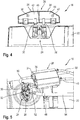
- FIG. 2 a heat energy store 28 arranged directly on the water-cooled dosing module 24 is shown.
- the dosing module 24 and the injection nozzle 26 are cooled by a partial flow of the coolant circuit of the internal combustion engine 12 during operation of the internal combustion engine 12.
- the coolant is introduced via an inlet nozzle 30 in the dosing module 24, and fed via a return pipe 32 back to the cooling circuit (not shown).
- the illustrated thermal energy storage 28 is integrated in the cooling circuit of the internal combustion engine, and is directly on the metering module 24, in particular the inlet pipe 30 and the return pipe 32, arranged.
- the thermal energy storage 28 is in the form of a tank for receiving liquid storage media, and has a first chamber 34 and a second chamber 36 each for receiving a liquid storage medium.
- the first chamber 34 is fluid-permeable directly connected to the inlet nozzle 30, 10 via the or an inlet 38 of the coolant circuit of the tractor can flow coolant into the first chamber 34 and from there into the inlet nozzle 30.
- the return pipe 32 of the dosing 24 is also fluidly connected directly to the second chamber 36 of the thermal energy storage 28, so that the coolant from the return pipe 32 through the second chamber 36 in a return line 40 which is fluidly connected to the second chamber 36 in the Cooling circuit of the vehicle or the tractor 10 can flow back.
- the thermal energy storage 28 on the metering module 24 in particular the inlet nozzle 30 and the return pipe 32, in a failure of the or the cooling pump and the coolant flow and / or a shutdown of the engine 12, the heat of the dosing 24 directly by the heat energy Memory 28 are received via the inlet nozzle 30 and the return pipe 32.
- the heat energy of the metering module 24 can be absorbed and stored by the liquid storage media in the first chamber 34 and the second chamber 36 of the thermal energy storage 28.
- the thermal energy store 28 is arranged substantially above the metering module 24 and the injection nozzle 26.
- natural thermal convection as a heat transfer mechanism can be effected within the first chamber 34 and the second chamber 36, respectively.
- the heated at the respective nozzle 30, 32 and heat energy absorbing storage medium within the first and / or second chamber 34, 36 rise, whereby cooler memory liquid storage medium can flow to the nozzle 30, 32.
- the absorption of heat energy from the metering module 24 can be improved by the heat energy storage 28, whereby overheating of the metering module 24 and in particular of the injection nozzle 26 can be avoided.
- FIG. 3 the heat energy store 28 arranged directly above the dosing module 24 is shown in a sectional view. It can be seen that the inlet nozzle 30 protrudes into the first chamber 34 with the first liquid storage medium 42, whereby a good transfer of heat energy from the Dosing module 24 can be ensured to the heat energy storage 28.
- the return pipe 32 of the metering module 24 hooks into the second chamber 36 of the thermal energy storage device 28, in which the second storage medium 44, in the form of water, in particular cooling water, is arranged.
- the first chamber 34 and the second chamber 36 of the thermal energy storage 28 are separated from each other by a partition wall 46 and each have an elongated extent.
- the heat energy storage 28 can be adapted to the respective available space within the engine compartment of the tractor 10, wherein ( FIG. 4 ) above the inlet stub 30 and the return stub 32 within the first chamber 34 and the second chamber 36, sufficient space should be provided for allowing natural thermal convection within the first and / or second chambers 34, 36.
- the coolant is passed through the inlet 38 into the first chamber 34 of the thermal energy storage 28, wherein the coolant within the first chamber 34 is the first storage medium 42.
- the coolant is passed from the first chamber 34 through the inlet port 30 for cooling the metering module 24 therethrough and leaves the metering module 24 via the return pipe 32 and enters the second chamber 36 of the thermal energy storage 28.
- the coolant in particular the cooling water, the second storage medium 44, until it is fed via the return line 40 back into the coolant circuit of the tractor 10.
- the second storage medium 44 is disposed with active cooling of the dosing 24 downstream of the dosing module 24, the second storage medium 44 has a higher temperature than the first storage medium 42, whereby the amount of storable heat energy of the second storage medium relative to the first storage medium 42nd something is reduced.
- the cooling water in the chambers 34, 36 forms the first storage medium 42 and the second storage medium 44th
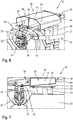
- the heat energy storage 28 is spaced and arranged above the dosing module 24.
- the dosing module 24 is arranged on a support module 48 above the catalyst 22, and thermally conductive, in particular fluid-permeable, connected to the metering module 24.
- the first chamber 34 of the thermal energy store 28 is connected via a feed line 50 to the inlet nozzle 30 of the metering module 24.
- the return pipe 32 of the metering module 24 is connected via a return line 52 to the second chamber 36 of the thermal energy storage 28.
- the injection nozzle 26 of the dosing module 24 is connected via an auxiliary conduit 54 to a reservoir of the auxiliary, not shown.
- the heat energy is conducted by the dosing module 24 (FIG. FIG. 6 ) via the inlet nozzle 30 and the return pipe 32 via the supply line 50 and the return line 52 to the first and the second chamber of the thermal energy storage 28, so that the heat energy of the dosing 24 by the first storage medium 42 and the second storage medium 44 can be recorded and stored ,
- the spaced arrangement of the thermal energy storage 28 to the metering module 24 and the injection nozzle 26 has the advantage that the thermal energy storage can be arranged in a space technically more favorable place within the engine compartment.
- the heat energy storage 28 is shown in a sectional side view, wherein between the heat energy storage 28 and the support module 48, a plate-shaped heat protection device 56 is arranged, which is in the form of a heat shield and the heat energy storage 28 protects against the radiation emitted by the catalyst 22 radiant heat. Thereby, absorption of heat energy from the catalyst 22 can be avoided, so that a higher amount of heat energy can be absorbed by the dosing module 24.
- the cut heat energy storage 28 shown has a substantially trapezoidal or substantially trapezoidal cross-section, wherein the catalyst 22 facing the bottom 58 is formed inclined or is formed inclined to form a slope.
- the gradient is formed by the inlet 38 and the return (not shown) to the metering module 24, so that even if damage to the inlet 38 and / or the return (not shown), a sufficiently large amount of storage medium, in particular cooling water, in the heat energy storage 28 for receiving heat energy of the dosing 24 is available.
- the heat protection device 56 is formed integrally with the support module 48.
- the thermal energy storage 28 is in this case with fastening means 60 detachably connected to the support module 48, and in particular the heat protection device 56
Description
Die Erfindung betrifft eine Vorrichtung zur Abgasnachbehandlung für ein Fahrzeug, insbesondere eine landwirtschaftliche Arbeitsmaschine, gemäß dem Oberbegriff des Anspruchs 1.The invention relates to a device for exhaust gas aftertreatment for a vehicle, in particular an agricultural working machine, according to the preamble of claim 1.
Landwirtschaftliche Arbeitsmaschinen wie Traktoren oder selbstfahrende Erntemaschinen sind üblicherweise mit einem Verbrennungsmotor ausgestattet, der zur Bereitstellung von Leistung für den Fahrantrieb sowie für weitere unterschiedliche Funktionen dient. Als Verbrennungsmotor wird dabei üblicherweise ein Dieselmotor eingesetzt, dessen Kraftstoff in einem oder mehreren Kraftstofftanks auf der Arbeitsmaschine mitgeführt wird. Die Abgase des Verbrennungsmotors enthalten unterschiedliche Schadstoffe, so dass bei modernen Arbeitsmaschinen die Abgase durch eine Vorrichtung zur Abgasnachbehandlung gereinigt werden. So wird beispielsweise die Konzentration von in den Abgasen enthaltenen Stickoxiden durch eine selektive katalytische Reduktion (SCR) reduziert. Dazu wird dem Abgas eine unmittelbar reduzierend wirkende Substanz, beispielsweise Ammoniak oder ein Vorprodukt davon, zugeführt, welches erst im Abgas die benötigten reduzierenden Substanzen freisetzt. Als Vorprodukt kann beispielsweise eine Harnstoff-Wasser-Lösung verwendet werden. Ammoniak wird bei der selektiven katalytischen Reduktion mit Stickstoffmonoxid und Stickstoffdioxid zu molekularem Stickstoff und Wasser umgewandelt. Die selektive katalytische Reduktion findet dabei in einem sogenannten SCR-Katalysator statt.Agricultural work machines, such as tractors or self-propelled harvesters, are typically equipped with an internal combustion engine that provides power to the drive and other functions. As a combustion engine, a diesel engine is usually used, the fuel is carried in one or more fuel tanks on the machine. The exhaust gases of the internal combustion engine contain different pollutants, so that in modern work machines, the exhaust gases are cleaned by a device for exhaust aftertreatment. For example, the concentration of nitrogen oxides contained in the exhaust gases is reduced by selective catalytic reduction (SCR). For this purpose, the exhaust gas is an immediately reducing substance, for example ammonia or a precursor thereof, supplied, which releases the required reducing substances only in the exhaust gas. As a precursor, for example, a urea-water solution can be used. Ammonia is converted to molecular nitrogen and water by selective catalytic reduction with nitrogen monoxide and nitrogen dioxide. The selective catalytic reduction takes place in a so-called SCR catalyst.
Das Einbringen des Reduktionsmittels, beispielsweise der Harnstoff-Wasser-Lösung, in die Abgase erfolgt über eine Dosiervorrichtung mit einer Einspritzdüse, durch welche das Reduktionsmittel unmittelbar in den Abgasstrom eingespritzt werden kann. Die Einspritzdüse ist dabei zur Dosierung des eingespritzten Reduktionsmittels üblicherweise elektrisch betätigbar. Ein Einspritzen des Reduktionsmittels in den Abgasstrom erfolgt dabei stromaufwärts des SCR-Katalysators.The introduction of the reducing agent, for example, the urea-water solution into the exhaust gases via a metering device with an injection nozzle, through which the reducing agent can be injected directly into the exhaust stream. The injection nozzle is usually electrically actuated for metering the injected reducing agent. An injection of the reducing agent into the exhaust gas flow takes place upstream of the SCR catalyst.
Aus der
Aus der
In der
Kühlwasserbasierte Systeme zur Kühlung eines Dosiermoduls sind aus
Bei einer unerwarteten Abschaltung des Verbrennungsmotors, beispielsweise aus Sicherheitsgründen, kann es auch zu einer Abschaltung des Kühlsystems kommen, wodurch auch die Kühlung des Dosiermoduls unterbrochen werden kann. Besonders bei einer Abschaltung des Verbrennungsmotors unter hoher Last wird aufgrund der herrschenden hohen Temperaturen eine große Wärmemenge von dem Verbrennungsmotor freigesetzt, welche auf das Dosiermodul und die Einspritzdüse wirkt. Zudem wird von dem Abgasstrang, in welchem das Dosiermodul und die Einspritzdüse unmittelbar angeordnet sind, eine hohe Wärmemenge an das Dosiermodul abgegeben, wodurch es zu Beeinträchtigungen des in der Einspritzdüse verbleibenden Reduktionsmittels kommen kann, wodurch eine weitere Funktion des Dosiermoduls beeinträchtigt werden kann. Zudem kann es aufgrund der hohen Temperaturen zu einer Beschädigung der elektrischen Verstellung des Dosiermoduls und insbesondere der Einspritzdüse kommen.In an unexpected shutdown of the engine, for example, for safety reasons, it may also lead to a shutdown of the cooling system, whereby the cooling of the metering module can be interrupted. Especially with a shutdown of the engine under high load due to the prevailing high temperatures, a large amount of heat is released from the engine, which acts on the dosing and the injection nozzle. In addition, a high amount of heat is discharged from the exhaust line, in which the metering module and the injection nozzle are directly disposed, to the metering module, whereby it can affect the remaining in the injector reducing agent, whereby a further function of the metering can be impaired. In addition, due to the high temperatures, damage to the electrical adjustment of the metering module and in particular of the injection nozzle may occur.
Es ist daher eine Aufgabe der vorliegenden Erfindung eine Vorrichtung zur Abgasnachbehandlung mit einem Dosiermodul bereitzustellen, welche insbesondere nach Unterbrechung einer Kühlung des Dosiermoduls ein Überhitzen des Dosiermoduls vermeidet und so eine Beschädigung des Dosiermoduls vermeidet und eine sichere Funktion gewährleisten kann.It is therefore an object of the present invention to provide a device for exhaust aftertreatment with a metering module, which avoids overheating of the metering module in particular after interrupting cooling of the metering and thus avoids damage to the metering and can ensure safe operation.
Die Aufgabe wird gelöst durch eine Vorrichtung zur Abgasnachbehandlung gemäß den Merkmalen des Anspruches 1. Vorteilhafte Ausgestaltungen der Erfindung sind in den Unteransprüchen angegeben.The object is achieved by a device for exhaust aftertreatment according to the features of claim 1. Advantageous embodiments of the invention are specified in the subclaims.
Eine Vorrichtung zur Abgasnachbehandlung für ein Fahrzeug, insbesondere eine landwirtschaftliche Arbeitsmaschine, mit einem Verbrennungsmotor, mit einem Dosiermodul, mit einer Einspritzdüse zum Einbringen eines Hilfsstoffes, insbesondere eines Reduktionsmittels wie Harnstoff, in einem Abgasstrom des Verbrennungsmotors, wobei erfindungsgemäß ein Wärmeenergiespeicher zur Speicherung von Wärmeene
gie des Dosiermoduls vorgesehen ist, welcher thermisch leitend mit dem Dosiermodul, und insbesondere der Einspritzdüse, verbunden ist.A device for exhaust aftertreatment for a vehicle, in particular an agricultural work machine, with an internal combustion engine, with a metering module, with an injection nozzle for introducing an adjuvant, in particular a reducing agent such as urea, in an exhaust stream of the internal combustion engine, wherein according to the invention a thermal energy storage for storing Wärmeene
gie of the metering module is provided, which is thermally conductively connected to the metering module, and in particular the injection nozzle.
Unter einem Wärmeenergiespeicher ist dabei ein Bauteil zu verstehen, welches thermisch leitend mit dem Dosiermodul, und insbesondere der Einspritzdüse des Dosiermoduls, verbunden ist, um Wärmeenergie von dem Dosiermodul und der Einspritzdüse aufzunehmen und zu speichern. Der Wärmeenergiespeicher kann dabei ein Bauteilsein, welches zusätzlich zu den die Funktion des Dosiermoduls gewährleistenden Bauteilen vorgesehen ist. Die Wärmeenergie kann dabei von dem Dosiermodul zu dem Wärmeenergiespeicher hin geleitet, und dort im Gegensatz zu einem Kühlkörper, gespeichert und nicht durch eine beispielsweise vergrößerte Oberfläche, an die Umgebung abgegeben werden. Der Wärmeenergiespeicher ist dabei derart ausgestaltet und ausgebildet, so dass eine hinreichend große Wärmeenergiemenge von dem Dosiermodul aufgenommen und gespeichert werden kann, um insbesondere bei einem schlagartigen Abschalten und Unterbrechen der Kühlung des Dosiermoduls ein Überhitzen des Dosiermoduls vermieden werden kann. Durch diesen Effekt, dass Wärmeenergie von dem Dosiermodul zu dem Wärmeenergiespeicher hingeleitet und dort gespeichert werden kann, kann insbesondere bei einem Abschalten des Verbrennungsmotors und einem Unterbrechen der Kühlung des Dosiermoduls ein Überhitzen des Dosiermoduls und insbesondere der Einspritzdüse vermieden werden. Dies hat den Vorteil, dass eine Hitzebelastung des Dosiermoduls und der Einspritzdüse verringert werden kann, und dadurch eine Beschädigung aufgrund zu hoher Temperaturen vermieden werden kann. Dies gewährleistet einen sicheren dauerhaften Betrieb des DosiermodulsIn this case, a thermal energy store means a component which is thermally conductively connected to the metering module, and in particular to the injection nozzle of the metering module, in order to absorb and store heat energy from the metering module and the injection nozzle. The heat energy store can be a component which is provided in addition to the components that ensure the function of the dosing module. In this case, the heat energy can be conducted from the dosing module to the heat energy store and, unlike a heat sink, stored there and not released to the environment through, for example, an enlarged surface. The thermal energy storage is configured and designed such that a sufficiently large amount of heat energy can be absorbed and stored by the metering module in order to avoid overheating of the metering module, in particular in the event of a sudden shutdown and interruption of the cooling of the metering module. By this effect, that thermal energy can be passed from the metering module to the thermal energy storage and stored there, overheating of the metering module and in particular of the injection nozzle can be avoided, in particular when the internal combustion engine is switched off and the cooling of the metering module is interrupted. This has the advantage that a heat load of the dosing and the injection nozzle can be reduced, and thereby damage due to high temperatures can be avoided. This ensures a safe permanent operation of the dosing
In einer bevorzugten Ausgestaltung der Erfindung ist der Wärmeenergiespeicher beabstandet zu oder unmittelbar an dem Dosiermodul und/oder der Einspritzdüse angeordnet. Hierbei kann ein Transport der Wärmeenergie von dem Dosiermodul und/oder der Einspritzdüse zu dem Wärmeenergiespeicher durch direkten Kontakt und/oder über eine Wärmeleitung erfolgen. Eine eine unmittelbare Anordnung des Wärmeenergiespeichers an dem Dosiermodul und/oder der Einspritzdüse hat den Vorteil, dass eine schnelle Ableitung der Wärmeenergie von dem Dosiermodul und/oder der Einspritzdüse zu dem Wärmeenergiespeicher ermöglicht wird, wodurch ein starker Temperaturanstieg an dem Dosiermodul und/oder der Einspritzdüse vermieden werden kann.In a preferred embodiment of the invention, the thermal energy store is arranged at a distance from or directly on the dosing module and / or the injection nozzle. In this case, a transport of the heat energy from the metering module and / or the injection nozzle to the heat energy storage by direct contact and / or via a heat conduction. An immediate arrangement of the thermal energy storage device on the metering module and / or the injection nozzle has the advantage that a rapid dissipation of the heat energy from the metering module and / or the injection nozzle is made possible to the thermal energy storage, whereby a strong increase in temperature at the metering module and / or the injection nozzle can be avoided.
In einer besonders bevorzugten Ausgestaltung der Erfindung weist der Wärmeenergiespeicher mindestens ein Speichermedium in Form einer Flüssigkeit oder eines Feststoffes zur Aufnahme der Wärmeenergie des Dosiermoduls auf. Das Speichermedium ist dabei das Material des Wärmeenergiespeichers, welcher zum Speichern der überwiegenden Menge der Wärmeenergie in dem Wärmeenergiespeicher dient. Ein Wärmeenergiespeicher mit einem Speichermedium in Form eines Feststoffes kann beispielsweise als ein einstückiger Körper ausgebildet sein. Ein Wärmeenergiespeicher mit einem Speichermedium in Form einer Flüssigkeit hingegen kann beispielsweise eines Behältnisses zur Aufnahme des flüssigen Speichermediums ausgebildet sein. Ein festes Speichermedium kann beispielsweise ein Metall, wie Kupfer, Eisen, oder Magnesium, sein. Ein Wärmeenergiespeicher mit einem festen Speichermedium kann beispielsweise in Form eines metallenen Bauteils innerhalb des Motorraumes, wie einer Tragstruktur, ausgebildet sein. Ein flüssiges Speichermedium kann beispielsweise Wasser sein, welches eine sehr hohe spezifische Wärmekapazität aufweist. Ein Wärmeenergiespeicher mit einem flüssigen Speichermedium kann dabei im Wesentlichen oberhalb an dem Dosiermodul und/oder der Einspritzdüse angeordnet sein. Dies hat den Vorteil, dass bei einem flüssigen Speichermedium neben der Wärmeleitung auch eine natürliche, thermische Konvektion, beispielsweise innerhalb des flüssigen Speichermediums, ermöglicht werden kann. Der Wärmeenergiespeicher kann dadurch zumindest teilweise zur schnellen Weiterleitung von Wärmeenergie zu einem Speichermedium mit hoher spezifischer Wärmekapizität und hohem Speichervermögen ausgelegt sein. Dadurch kann eine Aufnahme und Speicherung von Wärmeenergie des Dosiermoduls beschleunigt werden.In a particularly preferred embodiment of the invention, the heat energy storage on at least one storage medium in the form of a liquid or a solid for receiving the heat energy of the dosing. The storage medium is the material of the thermal energy storage, which serves to store the vast amount of heat energy in the heat energy storage. A heat energy store with a storage medium in the form of a solid may be formed, for example, as a one-piece body. By contrast, a heat energy store with a storage medium in the form of a liquid can be designed, for example, to form a container for holding the liquid storage medium. A solid storage medium may be, for example, a metal such as copper, iron, or magnesium. A thermal energy storage device with a solid storage medium may, for example, be in the form of a metal component within the engine compartment, such as a support structure. A liquid storage medium may be, for example, water, which has a very high specific heat capacity. A heat energy store with a liquid storage medium can be arranged substantially above the metering module and / or the injection nozzle. This has the advantage that in a liquid storage medium in addition to the heat conduction, a natural, thermal convection, for example, within the liquid storage medium, can be made possible. The thermal energy store can thereby be designed, at least in part, for the rapid transfer of heat energy to a storage medium with high specific heat capacity and high storage capacity. Thereby, a recording and storage of heat energy of the metering module can be accelerated.
In einer weiteren Ausgestaltung der Erfindung sind mindestens ein erstes und ein zweites Speichermedium vorgesehen, wobei die Speichermedien fest und/oder flüssig sein können und gleiche oder unterschiedliche spezifische Wärmekapazitäten aufweisen können. Dadurch kann der Wärmeenergiespeicher mehrere Speichermedien, beispielsweise mit unterschiedlichen spezifischen Wärmekapazitäten aufweisen, wodurch beispielsweise durch ein festes Speichermedium mit einer niedrigen spezifischen Wärmekapazität, wie Kupfer, eine Ableitung der Wärmeenergie von dem Dosiermodul hin zu einem beispielsweise flüssigen Speichermedium mit einer hohen spezifischen Wärmekapazität, beschleunigt werden kann. Dadurch kann eine schnelle Ableitung der Wärmeenergie von dem Dosiermodul erfolgen und eine hohe Wärmemenge in dem Wärmeenergiespeicher aufgenommen werdenIn a further embodiment of the invention, at least a first and a second storage medium are provided, wherein the storage media may be solid and / or liquid and may have the same or different specific heat capacities. As a result, the heat energy store can have a plurality of storage media, for example with different specific heat capacities, whereby, for example, a solid storage medium with a low specific heat capacity, such as copper, promotes a dissipation of the heat energy from the dosing module to, for example, a liquid storage medium with a high specific heat capacity can. This can be a fast Derivation of the heat energy done by the dosing and a high amount of heat are absorbed in the heat energy storage
In einer besonders bevorzugten Ausgestaltung der Erfindung ist der Wärmeenergiespeicher zur Aufnahme eines flüssigen Speichermediums in Form eines Tanks und/oder in Form einer Rohrleitung ausgebildet. Unter einer Rohrleitung ist dabei im Sinne der Erfindung auch ein Schlauch zu verstehen, da hierbei die Aufnahme des flüssigen Speichermediums im Vordergrund steht. Ein Wärmeenergiespeicher für ein flüssiges Speichermedium in Form eines Tanks kann dabei unmittelbar oder beabstandet zu dem Dosiermodul und/oder der Einspritzdüse angeordnet sein. Ein beabstandet zu dem Dosiermodul und/oder der Einspritzdüse angeordneter Wärmeenergiespeicher mit einem flüssigen Speichermedium kann dabei fluiddurchlässig über Rohrleitungen mit dem Dosiermodul verbunden sein. Die Rohrleitungen können dabei einen Durchmesser aufweisen, welcher eine natürliche thermische Konvektion, also eine durch die aufgenommene Wärmeenergie bedingte Stoffbewegung des flüssigen Speichermediums innerhalb des Tanks und/oder der Rohrleitungen ermöglichenIn a particularly preferred embodiment of the invention, the thermal energy store for receiving a liquid storage medium in the form of a tank and / or in the form of a pipeline is formed. Under a pipe is in the context of the invention, a hose to understand, as this is the recording of the liquid storage medium in the foreground. A thermal energy store for a liquid storage medium in the form of a tank can be arranged directly or at a distance from the dosing module and / or the injection nozzle. A spaced apart from the dosing module and / or the injection nozzle heat energy storage with a liquid storage medium can be fluid-permeable connected via pipes with the dosing. The pipelines can have a diameter which allows a natural thermal convection, that is to say a material movement of the liquid storage medium within the tank and / or the pipelines caused by the absorbed thermal energy
In einer besonders bevorzugten Ausgestaltung der Erfindung sind der Wärmespeicher und/oder das Dosiermodul, und insbesondere die Einspritzdüse, wassergekühlt. Eine Wasserkühlung des Dosiermoduls des Wärmeenergiespeichers und/oder der Einspritzdüse kann dabei beispielsweise mit einem aktiven Kühlkreislauf, welcher durch eine Pumpe betrieben wird, erfolgen. Die Kühlung des Wärmeenergiespeichers kann bei einem festen Speichermedium durch unmittelbaren Kontakt mit dem Kühlwasser erfolgen. Bei einem Wärmeenergiespeicher mit einem flüssigen Speichermedium kann eine Kühlung des Wärmeenergiespeichers beispielsweise durch einen Austausch des flüssigen Speichermediums erfolgen. Dies hat den Vorteil, dass nicht nur eine zügige Aufnahme der Wärmeenergie von dem Dosiermodul ermöglicht wird, sondern auch eine sehr große Speicherkapazität an Wärmeenergie durch den Austausch des flüssigen Speichermediums gewährleistet werden kann.In a particularly preferred embodiment of the invention, the heat accumulator and / or the metering module, and in particular the injection nozzle, are water-cooled. A water cooling of the dosing of the thermal energy storage and / or the injection nozzle can be done, for example, with an active cooling circuit, which is operated by a pump. The cooling of the thermal energy storage can be done in a solid storage medium by direct contact with the cooling water. In the case of a heat energy store with a liquid storage medium, cooling of the thermal energy store can take place, for example, by exchanging the liquid storage medium. This has the advantage that not only a rapid absorption of the heat energy is made possible by the dosing, but also a very large storage capacity can be ensured of thermal energy by replacing the liquid storage medium.
In einer weiteren besonders bevorzugten Ausgestaltung der Erfindung ist das flüssige Speichermedium Kühlwasser des Verbrennungsmotors. Ein Wärmeenergiespeicher, dessen flüssiges Speichermedium Kühlwasser des Verbrennungsmotors ist, kann derart an den Kühlkreislauf des Verbrennungsmotors angeschlossen sein, dass eine Kühlung des Wärmeenergiespeichers und/oder des Dosiermoduls durch zumindest einen Teilstrom des Kühlkreislaufs des Verbrennungsmotors erfolgen kann. Dies ermöglicht eine aktive Kühlung des Wärmeenergiespeichers, wenn der Kühlkreislauf des Verbrennungsmotors läuft, wodurch die Speicherung von Wärmeenergie in dem Wärmeenergiespeicher während des normalen Betriebes des Fahrzeuges, insbesondere der landwirtschaftlichen Arbeitsmaschine, vermieden werden kann. Das Kühlwasser innerhalb des Wärmeenergiespeichers kann dabei als quasistationär angesehen werden. Dies hat den Vorteil, dass bei einem Ausfall der Kühlung des Dosiermoduls und/oder des Wärmeenergiespeichers, der Wärmeenergiespeicher eine höhere Wärmemenge aufnehmen kann als ein Wärmeenergiespeicher ohne umgewälztes Kühlmittel. Ein Wärmeenergiespeicher, welcher zwei flüssige Speichermedien aufweist, kann derart an dem Kühlwasserkreislauf angeschlossen sein, dass ein erstes flüssiges Speichermedium stromaufwärts des Dosiermoduls in dem Kühlmittelkreislauf angeordnet ist, und ein zweites flüssiges Speichermedium stromabwärts von dem Dosiermodul angeordnet ist. Dabei kann bei einem Umwälzen des Kühlmittels des Verbrennungsmotors zunächst das Kühlwasser das erste flüssige Speichermedium austauschen, das Dosiermodul durchströmen, und das zweite flüssige Speichermedium austauschen. Bei einem Stillstand des Kühlmittelkreislaufs, also bei einer fehlenden Umwälzung, sind sowohl das erste Speichermedium als auch das zweite Speichermedium über das Kühlwasser wärmeleitend mit dem Dosiermodul und/oder der Einspritzdüse zur Aufnahme und Speicherung von Wärmeenergie verbunden.In a further particularly preferred embodiment of the invention, the liquid storage medium is cooling water of the internal combustion engine. A thermal energy storage, the liquid storage medium is cooling water of the internal combustion engine can be connected to the cooling circuit of the engine so that cooling of the heat energy storage and / or the metering can be done by at least a partial flow of the cooling circuit of the engine. This allows active cooling of the thermal energy storage when the engine cooling circuit is running, thereby avoiding the storage of thermal energy in the thermal energy storage during normal operation of the vehicle, particularly the agricultural machine. The cooling water within the heat energy storage can be regarded as quasi-stationary. This has the advantage that in case of failure of the cooling of the dosing and / or the heat energy storage, the heat energy storage can absorb a higher amount of heat than a heat energy storage without recirculated coolant. A thermal energy storage having two liquid storage media may be connected to the cooling water circuit such that a first liquid storage medium is disposed upstream of the metering module in the refrigerant circuit, and a second liquid storage medium is disposed downstream of the metering module. In this case, during a circulation of the coolant of the internal combustion engine, first the cooling water can exchange the first liquid storage medium, flow through the dosing module, and exchange the second liquid storage medium. At a standstill of the coolant circuit, so in a lack of circulation, both the first storage medium and the second storage medium via the cooling water heat conductively connected to the metering module and / or the injector for receiving and storing heat energy.
In einer weiteren Ausgestaltung der Erfindung weist der Wärmeenergiespeicher Kühlstrukturen zur Abgabe aufgenommener Wärmeenergie auf. Diese Kühlstrukturen können beispielsweise in Form einer außenseitig an dem Wärmeenergiespeicher angebrachten Profilierung ausgebildet sein, und dienen der Abfuhr und Ableitung von Wärmeenergie aus dem Wärmeenergiespeicher und wirken dabei als Kühlkörper. Dies hat den Vorteil, dass der Wärmeenergiespeicher nach Aufnahme der Wärmeenergie von dem Dosiermodul diese schneller an die Umgebung abgeben kann.In a further embodiment of the invention, the thermal energy store has cooling structures for emitting absorbed thermal energy. These cooling structures may be designed, for example, in the form of a profiling which is attached to the heat energy store on the outside, and serve for removing and discharging heat energy from the heat energy store and thereby acting as a heat sink. This has the advantage that the heat energy storage after receiving the heat energy from the dosing this can deliver faster to the environment.
In einer weiteren bevorzugten Ausgestaltung der Erfindung weist der Wärmeenergiespeicher mindestens eine Wärmeschutzvorrichtung auf, welche eine Aufnahme von anderer Wärmeenergie als der des Dosiermoduls verringert. Die Wärmeschutzvorrichtung reduziert die Aufnahme von Wärmeenergie von anderen Baugruppen des Fahrzeuges, wie des Verbrennungsmotors und/oder des Abgasstranges, welche beispielsweise in Form von Wärmestrahlung auf den Wärmeenergiespeicher übertragen werden können. Dadurch kann die Erwärmung des Wärmeenergiespeichers verringert werden, wodurch eine höhere Wärmeenergie von dem Dosiermodul und/oder der Einspritzdüse auf-genommen werden kann. Die Wärmeschutzvorrichtung kann beispielsweise in Form einer Isolierung, beispielsweise aus einem Material niedriger Wärmeleitfähigkeit, ausgebildet sein. Ebenso ist denkbar, dass die Wärmeschutzvorrichtung in Form eines Hitzeschildes gegen Strahlungswärme ausgebildet ist, wobei das Hitzeschild beabstandet zu dem Wärmeenergiespeicher angeordnet sein kann.In a further preferred embodiment of the invention, the thermal energy store has at least one heat protection device, which reduces a recording of thermal energy other than that of the dosing module. The thermal protection device reduces the absorption of heat energy from other components of the vehicle, such as the internal combustion engine and / or the exhaust line, which can be transmitted, for example in the form of heat radiation to the thermal energy storage. Thereby, the heating of the thermal energy storage can be reduced, whereby a higher heat energy from the dosing and / or the injection nozzle can be taken. The heat protection device can be designed, for example, in the form of an insulation, for example of a material of low thermal conductivity. It is also conceivable that the heat protection device is designed in the form of a heat shield against radiant heat, wherein the heat shield can be arranged spaced from the heat energy storage.
Die Erfindung betrifft weiterhin ein Fahrzeug, insbesondere eine landwirtschaftliche Arbeitsmaschine, mit mindestens einer Vorrichtung zur Abgasnachbehandlung, welche wie vorstehend aus- und weitergebildet ist.The invention further relates to a vehicle, in particular an agricultural work machine, with at least one device for exhaust aftertreatment, which is off and on as above.
Die Erfindung wird nachfolgend anhand von Ausführungs-beispielen näher erläutert. Daraus ergeben sich auch vorteilhafte Wirkungen und Effekte.
In den Figuren zeigt:
- Figur 1
- einen Traktor in schematischer Ansicht von der Seite mit einer erfindungsgemäßen Vorrichtung zur Abgasnachbehandlung;
- Figur 2
- eine Vorrichtung zur Abgasnachbehandlung mit einem Wärmeenergiespeicher;
- Figur 3
- eine perspektivische, geschnittene Ansicht des tankförmigen Wärmeenergiespeichers aus
Figur 2 ; - Figur 4
- eine geschnittene Darstellung des unmittelbar an dem Dosiermodul angeordneten Wärmeenergiespeichers aus
Figur 2 und Figur 3 ; - Figur 5
- eine perspektivische Darstellung eines beabstandet zu dem Dosiermodul angeordneten Wärmeenergiespeichers;
- Figur 6
- eine perspektivische, geschnittene Ansicht des Wärmeenergiespeichers in
Figur 5 ; und - Figur 7
- eine geschnittene Seitenansicht des Wärmeenergiespeichers aus
Figur 5 undFigur 6 .
In the figures shows:
- FIG. 1
- a tractor in a schematic view from the side with a device according to the invention for the exhaust aftertreatment;
- FIG. 2
- a device for exhaust aftertreatment with a heat energy storage;
- FIG. 3
- a perspective, sectional view of the tank-shaped heat energy storage
FIG. 2 ; - FIG. 4
- a sectional view of the arranged directly on the dosing module heat energy storage
FIG. 2 and FIG. 3 ; - FIG. 5
- a perspective view of a spaced apart from the metering module heat energy storage;
- FIG. 6
- a perspective, sectional view of the heat energy storage in
FIG. 5 ; and - FIG. 7
- a sectional side view of the heat energy storage
FIG. 5 andFIG. 6 ,
In
Die Einspritzdüse ist dabei zur Dosierung der eingespritzten Reduzierungsmittel bzw. Reduktionsmittelmenge elektrisch betätigbar, wobei die selektive katalytische Reduktion in dem Katalysator erfolgt. Das Dosiermodul 24 und die Einspritzdüse 26 sind der Wärmestrahlung des Verbrennungsmotors und besonders des Abgasstranges ausgesetzt, so dass das Dosiermodul 24 und die Einspritzdüse 26 zur Vermeidung einer Überhitzung während des Betriebes des Verbrennungsmotors 12 wassergekühlt sind, wobei eine Kühlung des Dosiermodules 24 und der Einspritzdüse 26 beispielsweise über einen Teilstrom des Kühlsystems (nicht dargestellt) des Verbrennungsmotors 12 erfolgen kann. Zur Vermeidung von Temperatur-spitzen und eine temperaturbedingte Beschädigung des Dosiermoduls 24 und/oder der Einspritzdüse 26 ist ein Wärmeenergiespeicher 28 benachbart und wärmeleitend an dem Dosiermodul 24 und der Einspritzdüse 26 angeordnet. So kann bei einem Abschalten des Verbrennungsmotors 12 und/oder einer Unterbrechung der Kühlung des Dosiermoduls 24 und/oder der Einspritzdüse 26 die von dem Verbrennungsmotor 12 und/oder dem Abgasstrang, insbesondere dem Katalysator 22 abgegebene Wärmeenergie zu einer Überhitzung des Dosiermoduls 24 und/oder der Einspritzdüse 26 führen, welche zu Funktionsstörungen oder sogar einem Ausfall des Dosiermoduls 24 und/oder der Einspritzdüse 26 führen können.The injection nozzle is electrically actuated for metering the injected reducing agent or amount of reducing agent, wherein the selective catalytic reduction takes place in the catalyst. The
Durch den thermisch leitend mit dem Dosiermodul 24 und/oder der Einspritzdüse 26 verbundenen Wärmeenergiespeicher 28 kann Wärmeenergie von dem Dosiermodul 24 und/oder der Einspritzdüse 26 durch Wärmeleitung auf den Wärmeenergiespeicher 28 übertragen und von diesem aufgenommen werden, wobei der Wärmeenergiespeicher 28 im Gegensatz zu einem Kühlkörper die aufgenommene Wärmeenergie von dem Dosiermodul 24 speichert. Der Wärmeenergiespeicher 28, welcher innerhalb des Motorraumes des Traktors 10 angeordnet ist, hat gegenüber einem Kühlkörper den Vorteil, dass die Wärmeenergie aufgenommen und gespeichert werden kann, wohingegen ein Kühlkörper aufgrund seiner geometrischen Form und eines Materials von hoher Wärmeleitfähigkeit eher die Wärme des Motorraumes aufnehmen und zusätzlich an das Dosiermodul 24 und/oder die Einspritzdüse 26 übertragen würde.By the thermally conductive with the
In
Der Wärmeenergiespeicher 28 ist in Form eines Tanks zur Aufnahme von flüssigen Speichermedien ausgebildet, und weist eine erste Kammer 34 und eine zweite Kammer 36 jeweils zur Aufnahme eines flüssigen Speichermediums auf. Die erste Kammer 34 ist dabei fluiddurchlässig mit dem Zulaufstutzen 30 unmittelbar verbunden, wobei über die bzw. einen Zulauf 38 des Kühlmittelkreislaufes des Traktors 10 Kühlmittels in die erste Kammer 34 und von dort in den Zulaufstutzen 30 gelangen kann. Der Rücklaufstutzen 32 des Dosiermoduls 24 ist ebenfalls fluiddurchlässig unmittelbar mit der zweiten Kammer 36 des Wärmeenergiespeichers 28 verbunden, so dass das Kühlmittel von dem Rücklaufstutzen 32 durch die zweite Kammer 36 in einen Rücklauf 40, welcher fluiddurchlässig mit der zweiten Kammer 36 verbunden ist, in den Kühlkreislauf des Fahr-zeuges bzw. des Traktors 10 zurückströmen kann. Durch die unmittelbare Anordnung des Wärmeenergiespeichers 28 an dem Dosiermodul 24, insbesondere dem Zulaufstutzen 30 und dem Rücklaufstutzen 32, kann bei einem Ausfall des bzw. der Kühlpumpe und des Kühlmittelstromes und/oder einer Abschaltung des Verbrennungsmotors 12 die Wärme des Dosiermoduls 24 unmittelbar durch den Wärmeenergie-speicher 28 über den Zulaufstutzen 30 und den Rücklauf-stutzen 32 aufgenommen werden.The
Die Wärmeenergie des Dosiermoduls 24 kann dabei von den flüssigen Speichermedien in der ersten Kammer 34 und der zweiten Kammer 36 des Wärmeenergiespeichers 28 aufgenommen und gespeichert werden. Der Wärmeenergiespeicher 28 ist im Wesentlichen oberhalb des Dosiermoduls 24 und der Einspritzdüse 26 angeordnet. Dadurch kann bei der Aufnahme der Wärme-energie des Dosiermoduls 24 durch die flüssigen Speichermedien eine natürliche thermische Konvektion als Mechanismus des Wärmetransportes jeweils innerhalb der ersten Kammer 34 und der zweiten Kammer 36 bewirkt werden. Dabei kann das an dem jeweiligen Stutzen 30, 32 erwärmte und Wärmeenergie aufnehmende Speichermedium innerhalb der ersten und/oder zweiten Kammer 34, 36 auf-steigen, wodurch kühleres speicherflüssiges Speichermedium an den Stutzen 30, 32 nachströmen kann. Hierdurch kann die Aufnahme von Wärmeenergie von dem Dosiermodul 24 durch den Wärmeenergiespeicher 28 verbessert werden, wodurch ein Überhitzen des Dosiermoduls 24 und insbesondere der Einspritzdüse 26 vermieden werden kann.The heat energy of the
In
Der Wärmeenergiespeicher 28 kann dabei dem jeweils zur Verfügung stehenden Bauraum innerhalb des Motorraumes des Traktors 10 angepasst werden, wobei (
In einem weiteren Ausführungsbeispiel (
In
- 1010
- Fahrzeugvehicle
- 1212
- Verbrennungsmotorinternal combustion engine
- 1414
- Abgasrohrexhaust pipe
- 1616
- Vorrichtung zur AbgasnachbehandlungDevice for exhaust aftertreatment
- 1818
- Fahrerkabinecab
- 2020
- AuspuffExhaust
- 2222
- Katalysatorcatalyst
- 2424
- Dosiermoduldosing
- 2626
- Einspritzdüseinjection
- 2828
- WärmeenergiespeicherThermal energy storage
- 3030
- Zulaufstutzeninlet connection
- 3232
- RücklaufstutzenReturn connectors
- 3434
- Erste KammerFirst chamber
- 3636
- Zweite KammerSecond Chamber
- 3838
- ZulaufIntake
- 4040
- Rücklaufreturns
- 4242
- Erstes SpeichermediumFirst storage medium
- 4444
- Zweites SpeichermediumSecond storage medium
- 4646
- Trennwandpartition wall
- 4848
- Trägermodulcarrier module
- 5050
- Zulaufleitungsupply line
- 5252
- RücklaufleitungReturn line
- 5454
- HilfsstoffleitungAuxiliary line
- 5656
- WärmeschutzvorrichtungThermal protector
- 5858
- Bodenground
- 6060
- Befestigungselementfastener
Claims (9)
- Apparatus (16) for exhaust gas aftertreatment for a vehicle (10), in particular an agricultural working machine, having an internal combustion engine (12), having a metering module (24) with an injection nozzle (26) for the introduction of an additive, in particular a reducing agent like urea, into an exhaust gas flow from the internal combustion engine (12), a heat energy storage means (28) for the storage of heat energy of the metering module (24), which is thermally conductingly connected to the metering module (24) and in particular the injection nozzle (26), characterised in that the heat energy storage means (28) is designed for receiving liquid storage media (42, 44) in the form of a tank which has a first chamber (34) and a second chamber (36) for respectively receiving a liquid storage medium (42, 44), wherein the liquid storage media (42, 44) are cooling water of the internal combustion engine (12) and the cooling water is passed out of the first chamber (34) by way of a feed connection (30) through the metering module (24) for cooling same and leaves the metering module (24) by of a return connection (32) and passes into the second chamber (36) of the heat energy storage means (28).
- Apparatus according to claim 1 characterised in that the heat energy storage means (28) is arranged in spaced relationship with or directly at the metering module (24) and/or the injection nozzle (26).
- Apparatus according to claim 1 or claim 2 characterised in that the heat energy storage means (28) has at least one storage medium (42, 44) in the form of a liquid or a solid for receiving the heat energy of the metering module (24).
- Apparatus according to one of the preceding claims characterised in that there are provided at least a first and a second storage medium (42, 44), wherein the storage media (42, 44) can be solid and/or liquid and can have the same or different specific heat capacities.
- Apparatus according to one of the preceding claims characterised in that the heat energy storage means (28) for receiving a liquid storage medium (42, 44) is in the form of a pipe.
- Apparatus according to one of the preceding claims characterised in that the heat energy storage means and/or the metering module and in particular the injection nozzle is water-cooled.
- Apparatus according to one of the preceding claims characterised in that the heat energy storage means (28) has cooling structures for the discharge of received heat energy.
- Apparatus according to one of the preceding claims characterised in that the heat energy storage means (28) has at least one heat protection device (56) which reduces absorption of heat energy other than that of the metering module (24).
- A vehicle, in particular an agricultural working machine, comprising at least one apparatus (16) for exhaust gas aftertreatment according to one of the preceding claims.
Applications Claiming Priority (1)
| Application Number | Priority Date | Filing Date | Title |
|---|---|---|---|
| DE102015114081.0A DE102015114081A1 (en) | 2015-08-25 | 2015-08-25 | Device for exhaust aftertreatment |
Publications (2)
| Publication Number | Publication Date |
|---|---|
| EP3135876A1 EP3135876A1 (en) | 2017-03-01 |
| EP3135876B1 true EP3135876B1 (en) | 2018-03-14 |
Family
ID=56289416
Family Applications (1)
| Application Number | Title | Priority Date | Filing Date |
|---|---|---|---|
| EP16176827.0A Active EP3135876B1 (en) | 2015-08-25 | 2016-06-29 | Device for aftertreatment of exhaust gas |
Country Status (2)
| Country | Link |
|---|---|
| EP (1) | EP3135876B1 (en) |
| DE (1) | DE102015114081A1 (en) |
Families Citing this family (1)
| Publication number | Priority date | Publication date | Assignee | Title |
|---|---|---|---|---|
| JP7448755B2 (en) * | 2021-03-18 | 2024-03-13 | 株式会社クボタ | Support structure for exhaust treatment device and engine with exhaust treatment device |
Citations (1)
| Publication number | Priority date | Publication date | Assignee | Title |
|---|---|---|---|---|
| US20140290222A1 (en) * | 2013-03-15 | 2014-10-02 | Komatsu Ltd. | Exhaust gas post-treatment unit and construction vehicle carrying same |
Family Cites Families (5)
| Publication number | Priority date | Publication date | Assignee | Title |
|---|---|---|---|---|
| DE102007013524A1 (en) | 2007-03-21 | 2008-09-25 | Robert Bosch Gmbh | Dosing module with improved acoustic properties |
| DE102012015768A1 (en) * | 2012-08-09 | 2013-03-07 | Daimler Ag | Cooling arrangement used for cooling outlet of metering device connected to exhaust line of vehicle, has heat absorbing unit that receives waste heat from outlet of metering device, to limit increase in outlet temperature |
| US9103600B2 (en) * | 2012-12-21 | 2015-08-11 | Caterpillar Inc. | Injector cooling apparatus and method |
| US9091193B2 (en) * | 2013-12-13 | 2015-07-28 | Cnh Industrial America Llc | Systems and methods for cooling a diesel exhaust fluid dosing module of an agricultural vehicle |
| US20140322088A1 (en) * | 2014-07-10 | 2014-10-30 | Perkins Engines Company Limited | Auxiliary coolant tank for exhaust aftertreatment system |
-
2015
- 2015-08-25 DE DE102015114081.0A patent/DE102015114081A1/en not_active Withdrawn
-
2016
- 2016-06-29 EP EP16176827.0A patent/EP3135876B1/en active Active
Patent Citations (1)
| Publication number | Priority date | Publication date | Assignee | Title |
|---|---|---|---|---|
| US20140290222A1 (en) * | 2013-03-15 | 2014-10-02 | Komatsu Ltd. | Exhaust gas post-treatment unit and construction vehicle carrying same |
Also Published As
| Publication number | Publication date |
|---|---|
| EP3135876A1 (en) | 2017-03-01 |
| DE102015114081A1 (en) | 2017-03-02 |
Similar Documents
| Publication | Publication Date | Title |
|---|---|---|
| EP2283214B1 (en) | Device for delivering a reductant and method for producing a motor vehicle | |
| DE10324482B4 (en) | Device for metering a reducing agent to the exhaust gas of an internal combustion engine | |
| DE112013000161B4 (en) | Exhaust after treatment unit and a construction vehicle containing them | |
| DE102013201591A1 (en) | LIQUID SUBSTANCE SYSTEM AND METHOD FOR OPERATING THE LIQUID SUBSTRATE SYSTEM | |
| DE102007000526B4 (en) | Exhaust gas purification device for an engine | |
| EP1939417B1 (en) | Exhaust system for an internal combustion engine | |
| DE102014003639A1 (en) | System and method for post shutdown temperature management and flushing | |
| DE112013000149B4 (en) | working vehicle | |
| DE102010017757A1 (en) | Rapid heating of a urea supply line for the aftertreatment of exhaust gases of an internal combustion engine | |
| DE102007047862A1 (en) | Fluid heater and emission control device | |
| DE102011086017A1 (en) | dosing | |
| WO2011157623A1 (en) | Device for preparing a reducing agent, comprising a system heating unit | |
| US20140369899A1 (en) | Multi-compartment phae separation tank for multiple reductant injectors | |
| DE102014217259A1 (en) | Fluid cooled reductant delivery unit for selective catalytic vehicle reduction systems | |
| DE102008043021A1 (en) | Exhaust control device | |
| DE102014111444A1 (en) | emission Control system | |
| DE102017200328A1 (en) | Urea container as heat storage | |
| DE102012004727A1 (en) | Device for providing liquid additive | |
| EP3135876B1 (en) | Device for aftertreatment of exhaust gas | |
| DE202014103956U1 (en) | System for purifying exhaust gases from an internal combustion engine | |
| DE102008061471B4 (en) | A method of melting and / or heating a reductant fluid in an SCR exhaust aftertreatment system | |
| EP1993865A1 (en) | Combined heating/warm water system for mobile applications | |
| WO2017190923A1 (en) | Storage tank for storing a freezable operating agent or auxiliary agent | |
| DE102013108922B4 (en) | Cooling jacket for an injector of an engine system | |
| WO2016206827A1 (en) | Cooling device |
Legal Events
| Date | Code | Title | Description |
|---|---|---|---|
| PUAI | Public reference made under article 153(3) epc to a published international application that has entered the european phase |
Free format text: ORIGINAL CODE: 0009012 |
|
| AK | Designated contracting states |
Kind code of ref document: A1 Designated state(s): AL AT BE BG CH CY CZ DE DK EE ES FI FR GB GR HR HU IE IS IT LI LT LU LV MC MK MT NL NO PL PT RO RS SE SI SK SM TR |
|
| AX | Request for extension of the european patent |
Extension state: BA ME |
|
| 17P | Request for examination filed |
Effective date: 20170901 |
|
| RBV | Designated contracting states (corrected) |
Designated state(s): AL AT BE BG CH CY CZ DE DK EE ES FI FR GB GR HR HU IE IS IT LI LT LU LV MC MK MT NL NO PL PT RO RS SE SI SK SM TR |
|
| GRAP | Despatch of communication of intention to grant a patent |
Free format text: ORIGINAL CODE: EPIDOSNIGR1 |
|
| INTG | Intention to grant announced |
Effective date: 20171121 |
|
| GRAS | Grant fee paid |
Free format text: ORIGINAL CODE: EPIDOSNIGR3 |
|
| GRAA | (expected) grant |
Free format text: ORIGINAL CODE: 0009210 |
|
| AK | Designated contracting states |
Kind code of ref document: B1 Designated state(s): AL AT BE BG CH CY CZ DE DK EE ES FI FR GB GR HR HU IE IS IT LI LT LU LV MC MK MT NL NO PL PT RO RS SE SI SK SM TR |
|
| REG | Reference to a national code |
Ref country code: GB Ref legal event code: FG4D Free format text: NOT ENGLISH |
|
| REG | Reference to a national code |
Ref country code: CH Ref legal event code: EP Ref country code: AT Ref legal event code: REF Ref document number: 979105 Country of ref document: AT Kind code of ref document: T Effective date: 20180315 |
|
| REG | Reference to a national code |
Ref country code: IE Ref legal event code: FG4D Free format text: LANGUAGE OF EP DOCUMENT: GERMAN |
|
| REG | Reference to a national code |
Ref country code: DE Ref legal event code: R096 Ref document number: 502016000701 Country of ref document: DE |
|
| REG | Reference to a national code |
Ref country code: FR Ref legal event code: PLFP Year of fee payment: 3 |
|
| REG | Reference to a national code |
Ref country code: NL Ref legal event code: MP Effective date: 20180314 |
|
| REG | Reference to a national code |
Ref country code: LT Ref legal event code: MG4D |
|
| PG25 | Lapsed in a contracting state [announced via postgrant information from national office to epo] |
Ref country code: LT Free format text: LAPSE BECAUSE OF FAILURE TO SUBMIT A TRANSLATION OF THE DESCRIPTION OR TO PAY THE FEE WITHIN THE PRESCRIBED TIME-LIMIT Effective date: 20180314 Ref country code: CY Free format text: LAPSE BECAUSE OF FAILURE TO SUBMIT A TRANSLATION OF THE DESCRIPTION OR TO PAY THE FEE WITHIN THE PRESCRIBED TIME-LIMIT Effective date: 20180314 Ref country code: HR Free format text: LAPSE BECAUSE OF FAILURE TO SUBMIT A TRANSLATION OF THE DESCRIPTION OR TO PAY THE FEE WITHIN THE PRESCRIBED TIME-LIMIT Effective date: 20180314 Ref country code: FI Free format text: LAPSE BECAUSE OF FAILURE TO SUBMIT A TRANSLATION OF THE DESCRIPTION OR TO PAY THE FEE WITHIN THE PRESCRIBED TIME-LIMIT Effective date: 20180314 Ref country code: NO Free format text: LAPSE BECAUSE OF FAILURE TO SUBMIT A TRANSLATION OF THE DESCRIPTION OR TO PAY THE FEE WITHIN THE PRESCRIBED TIME-LIMIT Effective date: 20180614 |
|
| PG25 | Lapsed in a contracting state [announced via postgrant information from national office to epo] |
Ref country code: BG Free format text: LAPSE BECAUSE OF FAILURE TO SUBMIT A TRANSLATION OF THE DESCRIPTION OR TO PAY THE FEE WITHIN THE PRESCRIBED TIME-LIMIT Effective date: 20180614 Ref country code: RS Free format text: LAPSE BECAUSE OF FAILURE TO SUBMIT A TRANSLATION OF THE DESCRIPTION OR TO PAY THE FEE WITHIN THE PRESCRIBED TIME-LIMIT Effective date: 20180314 Ref country code: GR Free format text: LAPSE BECAUSE OF FAILURE TO SUBMIT A TRANSLATION OF THE DESCRIPTION OR TO PAY THE FEE WITHIN THE PRESCRIBED TIME-LIMIT Effective date: 20180615 Ref country code: SE Free format text: LAPSE BECAUSE OF FAILURE TO SUBMIT A TRANSLATION OF THE DESCRIPTION OR TO PAY THE FEE WITHIN THE PRESCRIBED TIME-LIMIT Effective date: 20180314 Ref country code: LV Free format text: LAPSE BECAUSE OF FAILURE TO SUBMIT A TRANSLATION OF THE DESCRIPTION OR TO PAY THE FEE WITHIN THE PRESCRIBED TIME-LIMIT Effective date: 20180314 |
|
| PG25 | Lapsed in a contracting state [announced via postgrant information from national office to epo] |
Ref country code: MT Free format text: LAPSE BECAUSE OF FAILURE TO SUBMIT A TRANSLATION OF THE DESCRIPTION OR TO PAY THE FEE WITHIN THE PRESCRIBED TIME-LIMIT Effective date: 20180314 |
|
| PG25 | Lapsed in a contracting state [announced via postgrant information from national office to epo] |
Ref country code: RO Free format text: LAPSE BECAUSE OF FAILURE TO SUBMIT A TRANSLATION OF THE DESCRIPTION OR TO PAY THE FEE WITHIN THE PRESCRIBED TIME-LIMIT Effective date: 20180314 Ref country code: PL Free format text: LAPSE BECAUSE OF FAILURE TO SUBMIT A TRANSLATION OF THE DESCRIPTION OR TO PAY THE FEE WITHIN THE PRESCRIBED TIME-LIMIT Effective date: 20180314 Ref country code: ES Free format text: LAPSE BECAUSE OF FAILURE TO SUBMIT A TRANSLATION OF THE DESCRIPTION OR TO PAY THE FEE WITHIN THE PRESCRIBED TIME-LIMIT Effective date: 20180314 Ref country code: NL Free format text: LAPSE BECAUSE OF FAILURE TO SUBMIT A TRANSLATION OF THE DESCRIPTION OR TO PAY THE FEE WITHIN THE PRESCRIBED TIME-LIMIT Effective date: 20180314 Ref country code: AL Free format text: LAPSE BECAUSE OF FAILURE TO SUBMIT A TRANSLATION OF THE DESCRIPTION OR TO PAY THE FEE WITHIN THE PRESCRIBED TIME-LIMIT Effective date: 20180314 Ref country code: EE Free format text: LAPSE BECAUSE OF FAILURE TO SUBMIT A TRANSLATION OF THE DESCRIPTION OR TO PAY THE FEE WITHIN THE PRESCRIBED TIME-LIMIT Effective date: 20180314 Ref country code: IT Free format text: LAPSE BECAUSE OF FAILURE TO SUBMIT A TRANSLATION OF THE DESCRIPTION OR TO PAY THE FEE WITHIN THE PRESCRIBED TIME-LIMIT Effective date: 20180314 |
|
| PG25 | Lapsed in a contracting state [announced via postgrant information from national office to epo] |
Ref country code: SM Free format text: LAPSE BECAUSE OF FAILURE TO SUBMIT A TRANSLATION OF THE DESCRIPTION OR TO PAY THE FEE WITHIN THE PRESCRIBED TIME-LIMIT Effective date: 20180314 Ref country code: SK Free format text: LAPSE BECAUSE OF FAILURE TO SUBMIT A TRANSLATION OF THE DESCRIPTION OR TO PAY THE FEE WITHIN THE PRESCRIBED TIME-LIMIT Effective date: 20180314 Ref country code: CZ Free format text: LAPSE BECAUSE OF FAILURE TO SUBMIT A TRANSLATION OF THE DESCRIPTION OR TO PAY THE FEE WITHIN THE PRESCRIBED TIME-LIMIT Effective date: 20180314 |
|
| REG | Reference to a national code |
Ref country code: DE Ref legal event code: R097 Ref document number: 502016000701 Country of ref document: DE |
|
| PG25 | Lapsed in a contracting state [announced via postgrant information from national office to epo] |
Ref country code: PT Free format text: LAPSE BECAUSE OF FAILURE TO SUBMIT A TRANSLATION OF THE DESCRIPTION OR TO PAY THE FEE WITHIN THE PRESCRIBED TIME-LIMIT Effective date: 20180716 |
|
| PLBE | No opposition filed within time limit |
Free format text: ORIGINAL CODE: 0009261 |
|
| STAA | Information on the status of an ep patent application or granted ep patent |
Free format text: STATUS: NO OPPOSITION FILED WITHIN TIME LIMIT |
|
| PG25 | Lapsed in a contracting state [announced via postgrant information from national office to epo] |
Ref country code: DK Free format text: LAPSE BECAUSE OF FAILURE TO SUBMIT A TRANSLATION OF THE DESCRIPTION OR TO PAY THE FEE WITHIN THE PRESCRIBED TIME-LIMIT Effective date: 20180314 |
|
| 26N | No opposition filed |
Effective date: 20181217 |
|
| PG25 | Lapsed in a contracting state [announced via postgrant information from national office to epo] |
Ref country code: SI Free format text: LAPSE BECAUSE OF FAILURE TO SUBMIT A TRANSLATION OF THE DESCRIPTION OR TO PAY THE FEE WITHIN THE PRESCRIBED TIME-LIMIT Effective date: 20180314 |
|
| PG25 | Lapsed in a contracting state [announced via postgrant information from national office to epo] |
Ref country code: MC Free format text: LAPSE BECAUSE OF FAILURE TO SUBMIT A TRANSLATION OF THE DESCRIPTION OR TO PAY THE FEE WITHIN THE PRESCRIBED TIME-LIMIT Effective date: 20180314 Ref country code: LU Free format text: LAPSE BECAUSE OF NON-PAYMENT OF DUE FEES Effective date: 20180629 |
|
| REG | Reference to a national code |
Ref country code: IE Ref legal event code: MM4A |
|
| PG25 | Lapsed in a contracting state [announced via postgrant information from national office to epo] |
Ref country code: IE Free format text: LAPSE BECAUSE OF NON-PAYMENT OF DUE FEES Effective date: 20180629 |
|
| REG | Reference to a national code |
Ref country code: CH Ref legal event code: PL |
|
| PG25 | Lapsed in a contracting state [announced via postgrant information from national office to epo] |
Ref country code: TR Free format text: LAPSE BECAUSE OF FAILURE TO SUBMIT A TRANSLATION OF THE DESCRIPTION OR TO PAY THE FEE WITHIN THE PRESCRIBED TIME-LIMIT Effective date: 20180314 |
|
| PG25 | Lapsed in a contracting state [announced via postgrant information from national office to epo] |
Ref country code: CH Free format text: LAPSE BECAUSE OF NON-PAYMENT OF DUE FEES Effective date: 20190630 Ref country code: LI Free format text: LAPSE BECAUSE OF NON-PAYMENT OF DUE FEES Effective date: 20190630 |
|
| PG25 | Lapsed in a contracting state [announced via postgrant information from national office to epo] |
Ref country code: MK Free format text: LAPSE BECAUSE OF NON-PAYMENT OF DUE FEES Effective date: 20180314 Ref country code: HU Free format text: LAPSE BECAUSE OF FAILURE TO SUBMIT A TRANSLATION OF THE DESCRIPTION OR TO PAY THE FEE WITHIN THE PRESCRIBED TIME-LIMIT; INVALID AB INITIO Effective date: 20160629 |
|
| PG25 | Lapsed in a contracting state [announced via postgrant information from national office to epo] |
Ref country code: IS Free format text: LAPSE BECAUSE OF FAILURE TO SUBMIT A TRANSLATION OF THE DESCRIPTION OR TO PAY THE FEE WITHIN THE PRESCRIBED TIME-LIMIT Effective date: 20180714 |
|
| GBPC | Gb: european patent ceased through non-payment of renewal fee |
Effective date: 20200629 |
|
| PG25 | Lapsed in a contracting state [announced via postgrant information from national office to epo] |
Ref country code: GB Free format text: LAPSE BECAUSE OF NON-PAYMENT OF DUE FEES Effective date: 20200629 |
|
| REG | Reference to a national code |
Ref country code: AT Ref legal event code: MM01 Ref document number: 979105 Country of ref document: AT Kind code of ref document: T Effective date: 20210629 |
|
| PG25 | Lapsed in a contracting state [announced via postgrant information from national office to epo] |
Ref country code: AT Free format text: LAPSE BECAUSE OF NON-PAYMENT OF DUE FEES Effective date: 20210629 |
|
| P01 | Opt-out of the competence of the unified patent court (upc) registered |
Effective date: 20230516 |
|
| PGFP | Annual fee paid to national office [announced via postgrant information from national office to epo] |
Ref country code: FR Payment date: 20230628 Year of fee payment: 8 Ref country code: DE Payment date: 20230620 Year of fee payment: 8 |
|
| PGFP | Annual fee paid to national office [announced via postgrant information from national office to epo] |
Ref country code: BE Payment date: 20230620 Year of fee payment: 8 |