EP3135841B1 - Water spraying device for inflatable pool - Google Patents
Water spraying device for inflatable pool Download PDFInfo
- Publication number
- EP3135841B1 EP3135841B1 EP16186055.6A EP16186055A EP3135841B1 EP 3135841 B1 EP3135841 B1 EP 3135841B1 EP 16186055 A EP16186055 A EP 16186055A EP 3135841 B1 EP3135841 B1 EP 3135841B1
- Authority
- EP
- European Patent Office
- Prior art keywords
- wall
- air inlet
- inflatable
- pool assembly
- water
- Prior art date
- Legal status (The legal status is an assumption and is not a legal conclusion. Google has not performed a legal analysis and makes no representation as to the accuracy of the status listed.)
- Active
Links
Images


Classifications
-
- E—FIXED CONSTRUCTIONS
- E04—BUILDING
- E04H—BUILDINGS OR LIKE STRUCTURES FOR PARTICULAR PURPOSES; SWIMMING OR SPLASH BATHS OR POOLS; MASTS; FENCING; TENTS OR CANOPIES, IN GENERAL
- E04H4/00—Swimming or splash baths or pools
- E04H4/12—Devices or arrangements for circulating water, i.e. devices for removal of polluted water, cleaning baths or for water treatment
-
- B—PERFORMING OPERATIONS; TRANSPORTING
- B05—SPRAYING OR ATOMISING IN GENERAL; APPLYING FLUENT MATERIALS TO SURFACES, IN GENERAL
- B05B—SPRAYING APPARATUS; ATOMISING APPARATUS; NOZZLES
- B05B7/00—Spraying apparatus for discharge of liquids or other fluent materials from two or more sources, e.g. of liquid and air, of powder and gas
-
- E—FIXED CONSTRUCTIONS
- E04—BUILDING
- E04H—BUILDINGS OR LIKE STRUCTURES FOR PARTICULAR PURPOSES; SWIMMING OR SPLASH BATHS OR POOLS; MASTS; FENCING; TENTS OR CANOPIES, IN GENERAL
- E04H4/00—Swimming or splash baths or pools
- E04H4/0018—Easily movable or transportable swimming pools
- E04H4/0025—Easily movable or transportable swimming pools with inflatable parts
-
- A—HUMAN NECESSITIES
- A61—MEDICAL OR VETERINARY SCIENCE; HYGIENE
- A61H—PHYSICAL THERAPY APPARATUS, e.g. DEVICES FOR LOCATING OR STIMULATING REFLEX POINTS IN THE BODY; ARTIFICIAL RESPIRATION; MASSAGE; BATHING DEVICES FOR SPECIAL THERAPEUTIC OR HYGIENIC PURPOSES OR SPECIFIC PARTS OF THE BODY
- A61H33/00—Bathing devices for special therapeutic or hygienic purposes
- A61H33/02—Bathing devices for use with gas-containing liquid, or liquid in which gas is led or generated, e.g. carbon dioxide baths
- A61H2033/021—Nozzles having flow-regulation means
-
- A—HUMAN NECESSITIES
- A61—MEDICAL OR VETERINARY SCIENCE; HYGIENE
- A61H—PHYSICAL THERAPY APPARATUS, e.g. DEVICES FOR LOCATING OR STIMULATING REFLEX POINTS IN THE BODY; ARTIFICIAL RESPIRATION; MASSAGE; BATHING DEVICES FOR SPECIAL THERAPEUTIC OR HYGIENIC PURPOSES OR SPECIFIC PARTS OF THE BODY
- A61H2201/00—Characteristics of apparatus not provided for in the preceding codes
- A61H2201/01—Constructive details
- A61H2201/0103—Constructive details inflatable
-
- A—HUMAN NECESSITIES
- A61—MEDICAL OR VETERINARY SCIENCE; HYGIENE
- A61H—PHYSICAL THERAPY APPARATUS, e.g. DEVICES FOR LOCATING OR STIMULATING REFLEX POINTS IN THE BODY; ARTIFICIAL RESPIRATION; MASSAGE; BATHING DEVICES FOR SPECIAL THERAPEUTIC OR HYGIENIC PURPOSES OR SPECIFIC PARTS OF THE BODY
- A61H33/00—Bathing devices for special therapeutic or hygienic purposes
- A61H33/02—Bathing devices for use with gas-containing liquid, or liquid in which gas is led or generated, e.g. carbon dioxide baths
- A61H33/027—Gas-water mixing nozzles therefor
Definitions
- the present disclosure relates to a pool sprayer and to an inflatable water pool with the pool sprayer.
- Sprayers are not only used to add water to a water pool or spa, but are also used for massage and relaxation. Depending on each user's personal preference and other factors, existing sprayers may spray water into the pool with a strong force that is uncomfortable against the user's skin, or with a weak force that is insufficient to achieve a massaging effect.
- US 2007/0124855 A1 discloses a spa pool assembly which has a pool having an enclosing wall and a base that together defines an interior.
- the base has a plurality of inflatable sections that are divided by at least one air passage.
- a hose delivers air from outside the pool to the air passage, with the hose extending partially inside the enclosing wall and having a U-shaped section extending outside the enclosing wall at a vertical level that is higher than the top of the enclosing wall.
- WO 2015/085227 A1 discloses an inflatable pool, comprising a top wall or panel, bottom wall or panel, inner surrounding or side wall or panel and outer surrounding or side wall or panel.
- the outer side wall is concentric with and surrounds the inner side wall to define circular trough structure.
- the top wall or panel is connected to the top of the inner side wall and the outer side wall
- the bottom wall or panel is connected to the bottom of the inner side wall and the outer side wall
- an air chamber is generated by the top wall or panel, the bottom wall or panel, the inner side wall and the outer side wall.
- the pool also comprises a plurality of laminated interval or bracing panels.
- EP1138 307A2 discloses a spa pool which has an enclosing wall that has at least one inflatable chamber, and a plumbing system retained in the interior of the wall.
- the plumbing system includes a plurality of jet nozzles, and a plurality of hoses that couple the plurality of jet nozzles.
- the wall can have two openings that communicate the interior with the exterior of the spa pool, the two openings including a first opening coupled to an inlet for receiving water into the interior from a pump, and a second opening coupled to an outlet for delivering water from the interior to a pump.
- US 2003/0089797 discloses a spa jet for delivering water from an upstream source of water under pressure to the interior of a spa, the spa jet having a housing with an inlet tube communicating with the source of water and a chamber wall defining a generally cup shaped chamber.
- a form having an annular upstream portion is fixed against axial movement between the chamber wall the retaining ring.
- the form has a downstream portion extending from the annular portion in the form of a shaft aligned with the axis.
- the spa jet also has a rotor with a generally cylindrical body concentric with the axis, the body having a bearing surface extending around the shaft which supports the body for rotating.
- At least one nozzle passage extends through the rotor which collects water from the inlet tube and directs the water as a water jet into the spa at an angle sufficient to impart a turning moment to the rotor about the axis.
- the present disclosure provides a pool sprayer with the capability of providing an air-water mixture to the pool, if desired.
- the pool sprayer includes an outlet module for spraying water into the recess of the pool, a suction module for suctioning ambient air into the outlet module, and a connecting pipe that connects the outlet module and the suction module.
- an inflatable pool assembly is provided according to appended claim 1.
- an inflatable pool assembly which does not form part of the claimed invention includes: an inner wall defining a water cavity; an outer wall cooperating with the inner wall to define an inflatable chamber; a plurality of water sprayers, each of the plurality of water sprayers comprising: an outlet module positioned at least partially within the inflatable chamber and having a mixed outlet positioned at the inner wall, the mixed outlet is in fluid communication with an air inlet and a water inlet; and a suction module positioned vertically above the outlet module and at least partially within the inflatable chamber, the suction module having the air inlet positioned at the outer wall; a connecting pipe between the suction module and the outlet module.
- a method for manufacturing an inflatable pool assembly includes: coupling an inner wall to an outer wall to define an inflatable chamber; coupling a portion of a suction module to the outer wall, the suction module positioned at least partially within the inflatable chamber; coupling a portion of an outlet module to the inner wall, the outlet module positioned at least partially within the inflatable chamber; and coupling the outlet module and the suction module together by a connecting pipe.
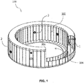
- the inflatable pool assembly 100 comprises an inner wall 102 and an outer wall 104 that are coupled together to define an inflatable chamber 1 therebetween.
- the inflatable pool assembly 100 also comprises a floor 105 that cooperates with inner wall 102 to define an internal cavity or recess 106 that is configured to hold water for swimming and/or bathing.
- the inflatable pool assembly 100 further comprises a plurality of pool sprayers 3 spaced around the water recess 106.
- the illustrative inflatable pool assembly 100 comprises six pool sprayers 3, although this number may vary. Each pool sprayer 3 can be operated independently to control the outlet flow volume of each pool sprayer 3.
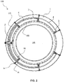
- Inflatable chamber 1 houses each pool sprayer 3.
- Each pool sprayer 3 includes an outlet module 32 coupled to inner wall 102, a suction module 34 coupled to outer wall 104, and an L-shaped connecting pipe 36 between the outlet module 32 and the suction module 36 that resides at least partially within inflatable chamber 1.
- inner-most portions of pool sprayer 3 described in further detail below, may extend inwardly from inner wall 102, towards inner recess 106.
- outer-most portions of pool sprayer 3, described in further detail below may extend outwardly from outer wall 104, away from inner recess 106.
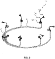
- Inflatable chamber 1 also includes one or more annular, flexible pipes 4 (e.g., hoses) which connect each outlet module 32 to inlet valve 2 as described in further detail below.
- each pool sprayer 3 is associated with its own pipe 4, so there are six pool sprayers 3 and six corresponding pipes 4, although these numbers may vary.
- Inlet valve 2 extends entirely through inflatable pool assembly 100 from outer wall 104, through inflatable chamber 1, and through inner wall 102 where a portion of inlet valve 2 extends into inner recess 106.
- Inlet valve 2 is configured to connect to an external water source, such as a residential water hose or another water reservoir (not shown), and may direct water directly into inner recess 106 of inflatable pool assembly 100.
- Inlet valve 2 may also indirectly provide water into inner recess 106 of inflatable pool assembly 100 through pipes 4 and outlet modules 32 of pool sprayers 3.
- inlet valve 2 receives water from the external water source (not shown) and directs water through each pipe 4 connected to inlet valve 2. The water then moves through outlet module 32 of each pool sprayer 3 where outlet module 32 delivers the water to inner recess 106 as described in further detail below.
- FIGS. 4-6 A single water sprayer 3 is shown in FIGS. 4-6 and described further below. However, the following description is also applicable to the other water sprayers 3 shown in FIGS. 1-3 .
- outlet module 32 is coupled with pipe 4 and connecting pipe 36 ( FIG. 3 ).
- Outlet module 32 includes a base body 322 having an internal passage 108 in fluid communication with three openings - a water inlet 110, an air inlet 306, and a mixed outlet 112.
- the water inlet 110 is located near the outer end of base body 322
- the mixed outlet 112 is located at the opposite inner end of base body 322
- the air inlet 306 is located therebetween.
- the water inlet 110 in base body 322 is configured to receive pipe 4.
- water inlet 110 is threaded to receive corresponding threads of nut 41 to couple pipe 4 with water inlet 110 of base body 322 as described in further detail below.
- water inlet 110 includes an alternate mechanism for coupling with pipe 4 for example, pins or clamps.
- a hollow plug 42 and nut 41 facilitate coupling pipe 4 to base body 322.
- plug 42 When plug 42 is inserted into pipe 4, the diameter of pipe 4 is enlarged. This increase in diameter provides a snug fit between pipe 4 and nut 41 that prevents pipe 4 from withdrawing out of nut 41, thereby preventing the connection between pipe 4 and water inlet 110 of base body 322 from loosening.
- water inlet 110 is configured to be facing substantially downwards towards the ground. However, in an alternative embodiment, water inlet 110 can be configured to face any direction along the external surface of base body 322.
- Air inlet 306 is also positioned along the external surface of the base body 322, and air inlet 306 is in fluid communication with both water inlet 110 and mixed outlet 112 via internal passage 108, as described below. Air inlet 306 receives connecting pipe 36 ( FIG. 3 ), which serves to couple suction module 34 to outlet module 32 as described in further detail below. In the illustrative embodiment, air inlet 306 is threaded to couple to corresponding threads on connecting pipe 36. In an alternate embodiment, air inlet 306 includes an alternate mechanism for coupling with connecting pipe 36 for example, pins or clamps. In the illustrative embodiment, air inlet 306 is configured to be facing substantially upwards opposite the water inlet 110. However, it is contemplated that in alternative embodiments, air inlet 306 can be configured to face any direction along the external surface of base body 322.
- internal passage 108 is defined by base body 322, and internal passage 108 enables fluid communication between air inlet 306, water inlet 110, and mixed outlet 112.
- internal passage 108 extends substantially through length L of base body 322.
- base body 322 is substantially cylindrical and defines internal passage 108 which is substantially cylindrical as well.
- base body 322 may take the form of another shape such as, for example, a cube, cone, pyramid, rectangular prism, etc.
- internal passage 108 may take the form of another shape within base body 322 such as, for example, a cube, cone, pyramid, rectangular prism, etc.
- Base body 322 further includes a soft plastic sleeve 308 with an end surface 309, both of which function to assist in receiving inner wall 102 ( FIG. 6 ) and adjustable end cover 326.
- soft sleeve 308 is integrally formed with end surface 309 and coupled to base body 322.
- soft sleeve 308 and end surface 309 are discrete parts coupled to one another and coupled to base body 322.
- soft sleeve 308 and end surface 309 are integrally formed with each other and base body 322. End surface 309 of soft sleeve 308 can be welded, adhered or otherwise connected to an inner wall 102 of inflatable pool assembly 100 to create a sealing effect between outlet module 32 and inner wall 102.
- Outlet module 32 further includes rotating valve spool 324 that is coupled to adjustable end cover 326 via a lock portion 302 as described in further detail below.
- adjustable end cover 326 and rotating valve spool 324 are substantially disposed within internal passage 108.
- Adjustable end cover 326 includes rim 307, which forms the inner-most portion of the outlet module 32 that extends inwardly from inner wall 102 of inflatable pool assembly 100 for access by a user, as described in further detail below.
- Rotating valve spool 324 is a hollow construct that includes a lock portion 302, a connecting portion 301, and an adjustable portion 303.
- lock portion 302 is coupled to adjustable end cover 326 such that when the user rotates the adjustable end cover 326, rotating valve spool 324 rotates as well.
- the rotation of rotating valve spool 324 adjusts the water flow area of internal passage 108 and the amount of water flow by controlling the alignment of gap 304 with respect to other portions of outlet module 32 as described in further detail below.
- Adjustable portion 303 has a gap 304 disposed along the external surface of adjustable portion 303.
- the configuration of gap 304 within outlet module 32 controls the volumetric flow rate of water through outlet module 32.
- gap 304 is aligned with water inlet 110 of base body 322
- the volume of water flow exiting outlet module 32 is increased as water is able to move through gap 304 and internal passage 108 substantially unimpeded.
- gap 304 is only partially aligned or not aligned with water inlet 110 of base body 322
- the volume of water flow through internal passage 108 and out of outlet module 32 is reduced because the solid exterior surface of the adjustable portion 303 provides a flow barrier as the water moves through internal passage 108.
- Connecting portion 301 also includes one or more radial holes 305 that correspond with air inlet 306 and are disposed along the external surface of base body 322. Holes 305 and air inlet 306 communicate with suction module 34, the structure of which is described in further detail below.
- suction module 34 includes air inlet valve base 341, a first check valve 343, and air inlet valve cover 342.
- Air inlet valve base 341 defines an air passageway substantially therethrough.
- air inlet valve base 341 is substantially conical and defines an air passageway which is substantially cylindrical.
- air inlet valve base 341 may take the form of another shape such as, for example, a cube, cylinder, pyramid, rectangular prism, etc.
- the air passageway defined by air inlet valve base 341 may take the form of another shape such as, for example, a cube, cone, pyramid, rectangular prism, etc.
- Air inlet valve base 341 further includes a soft plastic sleeve 344 with an end surface 345 that assists in engaging with outer wall 104 ( FIG. 6 ).
- soft sleeve 344 is integrally formed with end surface 345 and coupled to air inlet valve base 341.
- soft sleeve 344 and end surface 345 are discrete parts and are coupled to one another and coupled to air inlet valve base 341.
- soft sleeve 344 and end surface 345 are integrally formed with air inlet valve base 341. End surface 345 of soft sleeve 344 on air inlet valve base 341 can be welded, adhered, or otherwise connected to outer wall 104 of inflatable pool assembly 100 to create a sealing effect between outer wall 104 and suction module 34.
- Air inlet valve base 341 has an opening 363 that is in fluid communication with the air passageway defined by air inlet valve base 341 and is coupled to connecting pipe 36.
- opening 363 is threaded at one of its ends to engage with corresponding threads of nut 362 as described in further detail below.
- opening 363 includes alternate mechanisms for coupling with connecting pipe 36 for example, pins or clamps.
- a hollow plug 364 and nut 362 facilitate the coupling of air inlet valve base 341 to connecting pipe 36 similar to the coupling of base body 322 and pipe 4.
- Plug 364 is inserted into connecting pipe 36 enlarging the diameter of connecting pipe 36. The increase in diameter provides a snug fit between connecting pipe 36 and nut 362 that prevents connecting pipe 36 from withdrawing out of nut 362, thereby preventing the connection between connecting pipe 36 and opening 363 from loosening.
- connecting pipe 36 is coupled to air inlet 306 of outlet module 32 ( FIG. 4 ) using another nut 362 and hollow plug 364 similar to those described above with respect to the air inlet valve base 341.
- Air inlet valve cover 342 has a distal end with a rim 346.
- Rim 346 of air inlet valve cover 342 is the outer-most portion of suction module 34 that extends outwardly from outer wall 104.
- the illustrative rim 346 defines a plurality of radial inlets 346A to permit air to enter air inlet valve cover 342 radially.
- outer wall 104 FIG. 6
- air inlet valve cover 342 is substantially disposed within inflatable chamber 1 such that rim 346 of air inlet valve cover 342 is substantially in line with the thickness of outer wall 104.
- First check valve 343 is disposed within the air passageway defined by air inlet valve base 341.
- a second check valve 328 ( FIG. 4 ) may also be provided in air inlet 306 of base body 322 to permit the flow of air into outlet module 32 while preventing the back-flow of water into suction module 34.
- check valves 328, 343 are pulled into an open configuration, and ambient air outside inflatable pool assembly 100 is pulled through rim 346, air inlet valve base 341, connecting pipe 36, and into base body 322 of outlet module 32.
- check valves 328 and 343 are in a default closed configuration, and water is prevented from back-flowing into suction module 34.
- Positioning the suction module 34 vertically above and radially in line with outlet module 32, as shown in FIG. 6 may also deter water from back-flowing into suction module 34.
- FIG. 6 shows outlet module 32, suction module 34, and connecting pipe 36 as assembled.
- water is fed directly through inlet valve 2 ( FIG. 2 ) to initially fill inner recess 106 of inflatable pool assembly 100.
- inner recess 106 is sufficiently filled with water, e.g. the water level is substantially near or above the location of rim 307, an air-water mixture may be provided from one or more pool sprayers 3 by selectively opening the corresponding adjustable end covers 326.
- a negative pressure is created within base body 322.
- the generated negative pressure moves check valves 328, 343 from a default closed configuration ( FIG. 6 ) to an open configuration where ambient air is then suctioned into suction module 34 by the negative pressure.
- the air then moves through connecting pipe 36 and enters base body 322 through holes 305 where it mixes with water flowing through internal passage 108 of outlet module 32 in base body 322 to create an air-water mixture (i.e., bubbles are created within the stream of water) that exits outlet module 32 via the mixed outlet 112.
- the release of the air-water mixture into the inner recess 106 from each pool sprayer 3 may be controlled by the user. If the user wants the air-water mixture to be delivered with little or no force, the user can partially or entirely close each pool sprayer 3 by rotating closed the corresponding adjustable end cover 326. On the other hand, if the user wants the air-water mixture to be delivered with higher force, such as for a massaging effect, the user can open each pool sprayer 3 by rotating open the corresponding adjustable end cover 326.
Landscapes
- Engineering & Computer Science (AREA)
- Architecture (AREA)
- Civil Engineering (AREA)
- Structural Engineering (AREA)
- Health & Medical Sciences (AREA)
- Water Supply & Treatment (AREA)
- Public Health (AREA)
- Massaging Devices (AREA)
- Pain & Pain Management (AREA)
- Physical Education & Sports Medicine (AREA)
- Rehabilitation Therapy (AREA)
- Life Sciences & Earth Sciences (AREA)
- Animal Behavior & Ethology (AREA)
- General Health & Medical Sciences (AREA)
- Veterinary Medicine (AREA)
- Epidemiology (AREA)
- Nozzles (AREA)
- Bathtubs, Showers, And Their Attachments (AREA)
Priority Applications (1)
| Application Number | Priority Date | Filing Date | Title |
|---|---|---|---|
| PL16186055T PL3135841T3 (pl) | 2015-08-26 | 2016-08-26 | Urządzenie do spryskiwania wodą dla nadmuchiwanego basenu |
Applications Claiming Priority (1)
| Application Number | Priority Date | Filing Date | Title |
|---|---|---|---|
| CN201520650954.7U CN204850582U (zh) | 2015-08-26 | 2015-08-26 | 水池喷头及应用此喷头的充气水池 |
Publications (2)
| Publication Number | Publication Date |
|---|---|
| EP3135841A1 EP3135841A1 (en) | 2017-03-01 |
| EP3135841B1 true EP3135841B1 (en) | 2020-04-15 |
Family
ID=54741147
Family Applications (1)
| Application Number | Title | Priority Date | Filing Date |
|---|---|---|---|
| EP16186055.6A Active EP3135841B1 (en) | 2015-08-26 | 2016-08-26 | Water spraying device for inflatable pool |
Country Status (4)
| Country | Link |
|---|---|
| US (1) | US10087644B2 (pl) |
| EP (1) | EP3135841B1 (pl) |
| CN (1) | CN204850582U (pl) |
| PL (1) | PL3135841T3 (pl) |
Cited By (1)
| Publication number | Priority date | Publication date | Assignee | Title |
|---|---|---|---|---|
| EP4616932A1 (en) * | 2024-03-15 | 2025-09-17 | Dongguan Polyfilm Plastic Products Company Limited | Spraying device and pool |
Families Citing this family (12)
| Publication number | Priority date | Publication date | Assignee | Title |
|---|---|---|---|---|
| CN207332380U (zh) * | 2017-07-28 | 2018-05-08 | 上海荣威塑胶工业有限公司 | 充气水池的按摩管路系统 |
| WO2019148380A1 (en) * | 2018-01-31 | 2019-08-08 | Bestway Inflatables & Material Corp. | Waterfall providing apparatus and system for pool or spa |
| JP6994399B2 (ja) * | 2018-02-05 | 2022-01-14 | 前澤化成工業株式会社 | 水栓柱 |
| CN211622779U (zh) * | 2019-07-19 | 2020-10-02 | 上海荣威塑胶工业有限公司 | 用于水池的水循环系统及水池 |
| USD938540S1 (en) * | 2019-10-23 | 2021-12-14 | Emily Catherine Vaca | Tufted pool |
| USD967321S1 (en) * | 2022-03-03 | 2022-10-18 | Maoqun Jiang | Water spray swimming pool |
| CN115162793B (zh) * | 2022-06-14 | 2023-07-25 | 淮安市美欣机电有限公司 | 高强度的充气泳池 |
| USD995686S1 (en) * | 2022-09-21 | 2023-08-15 | Shenzhen Tiandeng Electronic Commerce Co., Ltd. | Folding bath tub with sprinkler |
| CN221430917U (zh) * | 2023-06-21 | 2024-07-30 | 上海荣威塑胶工业有限公司 | 内置充气座椅的按摩充气水池 |
| USD1008427S1 (en) * | 2023-08-03 | 2023-12-19 | Yangzhao Lou | Inflatable bathtub |
| CN220654414U (zh) * | 2023-08-17 | 2024-03-26 | 东莞市红宇塑胶有限公司 | 一种宠物泳池 |
| USD1103404S1 (en) * | 2025-04-16 | 2025-11-25 | Jiaxing Virpol Sanitary Ware co., LTD. | Soft spa |
Family Cites Families (43)
| Publication number | Priority date | Publication date | Assignee | Title |
|---|---|---|---|---|
| US3677474A (en) | 1970-05-06 | 1972-07-18 | Anzen Prod | Adjustable liquid discharge jet |
| US4168705A (en) | 1977-05-31 | 1979-09-25 | Jacuzzi Bros., Inc. | Float and check valve for hydrotherapy unit air intake |
| US4637080A (en) | 1985-12-19 | 1987-01-20 | Hutchinson Charles H | Air volume control |
| JPH0543879Y2 (pl) | 1988-04-07 | 1993-11-05 | ||
| JPH0242631U (pl) | 1988-09-19 | 1990-03-23 | ||
| GB8917882D0 (en) | 1989-08-04 | 1989-09-20 | Ph Pool Services Ltd | Jet units for whirlpool-bath systems |
| US5495627A (en) | 1993-11-02 | 1996-03-05 | Leaverton; Gregg | Combination adjustable jet valve |
| WO1996017576A1 (en) | 1994-12-09 | 1996-06-13 | Kohler Co. | Whirlpool jet manifold |
| USD389245S (en) | 1995-12-20 | 1998-01-13 | Robert Lopez | Hydrotherapy jet |
| US6000073A (en) | 1996-07-10 | 1999-12-14 | Eddington; Richard Alex | Jet zone distribution system for spas |
| US5987663A (en) | 1996-07-10 | 1999-11-23 | Bullfrog International, L.C. | Modular system for spas and bathing systems |
| US5754989A (en) | 1996-07-10 | 1998-05-26 | Ludlow; David Jon | Plumbing and shell system for spa |
| US5956784A (en) | 1996-10-08 | 1999-09-28 | American Products, Inc. | Hydro-therapy spa jet nozzle |
| NL1005235C2 (nl) | 1997-02-10 | 1998-08-11 | Sanilux Bv | Whirlpool-injector en whirlpool-systeem. |
| US5801262A (en) | 1997-06-30 | 1998-09-01 | General Electric Company | Process for preparing polysiloxane microspheres with a narrow size distribution |
| US5920924A (en) | 1997-11-10 | 1999-07-13 | Pinciaro; John | Hydrotherapy jet and fixtures for spa tubs and pools and a method of installation |
| US6322004B1 (en) | 1998-10-24 | 2001-11-27 | Pentair Pool Products, Inc | Spa jet |
| US6141804A (en) | 1999-06-04 | 2000-11-07 | Pinciaro; John | Hydrotherapy jet system adapted for quick connection to air and water plumbing |
| US6334224B1 (en) | 1999-12-09 | 2002-01-01 | Hydrabaths, Inc. | Whirlpool jet assembly |
| US6357059B1 (en) * | 2000-03-28 | 2002-03-19 | Pleasure Time Products (Hk) Limited | Portable spa |
| US6510277B1 (en) | 2000-10-04 | 2003-01-21 | Waterway, Inc. | Pool and spa components with fiber optic illumination |
| US6543067B2 (en) | 2001-07-19 | 2003-04-08 | Bullfrog International, L.C. | Integrated manifold system for spas |
| US6491238B1 (en) | 2001-11-13 | 2002-12-10 | Pentair Pool Products, Inc. | Rotary spa jet incorporating a rotating nozzle supported by a radial ball bearing intended to reduce clogging of the bearing |
| US6691336B2 (en) | 2001-11-14 | 2004-02-17 | Pentair Pool Products, Inc. | High flow cyclone spa jet |
| US6745413B2 (en) | 2002-08-08 | 2004-06-08 | Precision Design Concepts, Llc | Hydrotherapy jet system having fluid line quick connector adapted for multiple sizes of jet fixture bodies and other plumbing fittings |
| US7493665B2 (en) * | 2003-04-01 | 2009-02-24 | Jack Williams | Dual-chamber water jet assembly for in-ground pools or spas |
| AU2004243126B2 (en) | 2003-05-30 | 2009-10-08 | Kipley Roydon Marks | Bath aeration |
| US7644452B2 (en) | 2003-08-22 | 2010-01-12 | B & S Plastics, Inc. | Hydrotherapy jet with adjustable air and water inlets |
| EP1811884B1 (en) | 2004-10-21 | 2018-02-14 | Bullfrog International, L.C. | Spas and bathing systems with upgradeable and interchangeable jet stations |
| US7849529B2 (en) | 2005-04-14 | 2010-12-14 | Bedard Paul R | Air injector system apparatus and methods for a tub or spa |
| US8095998B2 (en) | 2005-05-23 | 2012-01-17 | Ideal Time Consultants Limited | Portable spa |
| US20060260038A1 (en) | 2005-05-23 | 2006-11-23 | Lau Vincent W | Portable spa |
| US7797770B2 (en) | 2005-05-23 | 2010-09-21 | Ideal Time Consultants. Limited | Portable spa |
| US20070079433A1 (en) | 2005-10-07 | 2007-04-12 | Pronto Production Abm Inc. | Hydrotherapy assembly for a swimming pool |
| US7950077B2 (en) | 2005-12-05 | 2011-05-31 | Bowles Fluidics Corporation | Spa jet yielding increased air entrainment rates |
| US7743437B2 (en) | 2006-06-15 | 2010-06-29 | G-G Distribution And Development Co., Inc. | Apparatus and method for jet aeration |
| US8869320B1 (en) | 2006-10-04 | 2014-10-28 | Aland Santamarina | Compact spa jet with enhanced air effects |
| US20080134425A1 (en) | 2006-11-22 | 2008-06-12 | Bradford Thomas Tatum | Portable spa with interchangeable overlay panels |
| US9377147B2 (en) | 2007-12-14 | 2016-06-28 | B&S Plastics Inc. | Multi-jet manifold |
| US20120005819A1 (en) | 2010-07-09 | 2012-01-12 | As Ip Holdco, L.L.C. | Whirlpool Jet Nozzle Assembly and Jet Apparatus |
| PL2914232T3 (pl) | 2012-11-05 | 2020-08-10 | Bullfrog International, L.C. | Systemy spa i systemy kąpielowe z zaawansowanymi wymiennymi modułami dyszowymi |
| WO2015010058A2 (en) | 2013-07-18 | 2015-01-22 | Intex Recreation Corp. | Inflatable spa |
| PL3077606T3 (pl) | 2013-12-05 | 2019-09-30 | Intex Recreation Corp. | Basen dmuchany |
-
2015
- 2015-08-26 CN CN201520650954.7U patent/CN204850582U/zh not_active Expired - Lifetime
-
2016
- 2016-08-25 US US15/247,468 patent/US10087644B2/en active Active
- 2016-08-26 PL PL16186055T patent/PL3135841T3/pl unknown
- 2016-08-26 EP EP16186055.6A patent/EP3135841B1/en active Active
Non-Patent Citations (1)
| Title |
|---|
| None * |
Cited By (1)
| Publication number | Priority date | Publication date | Assignee | Title |
|---|---|---|---|---|
| EP4616932A1 (en) * | 2024-03-15 | 2025-09-17 | Dongguan Polyfilm Plastic Products Company Limited | Spraying device and pool |
Also Published As
| Publication number | Publication date |
|---|---|
| PL3135841T3 (pl) | 2020-10-19 |
| EP3135841A1 (en) | 2017-03-01 |
| US20170058544A1 (en) | 2017-03-02 |
| CN204850582U (zh) | 2015-12-09 |
| US10087644B2 (en) | 2018-10-02 |
Similar Documents
| Publication | Publication Date | Title |
|---|---|---|
| EP3135841B1 (en) | Water spraying device for inflatable pool | |
| US4525881A (en) | Hydrotherapy system for tubs, spas or pools | |
| US4731887A (en) | Water entrainment hydrotherapy jet assembly | |
| CA2955104C (en) | Water spraying device for above ground pool | |
| US20200232237A1 (en) | Pipeline system of inflatable spa | |
| US4985943A (en) | Two-stage adjustable hydrotherapeutic jet and method | |
| US8978174B2 (en) | Water jet housing with internal sleeve for limiting water and/or air flow | |
| US9125792B2 (en) | Spray pattern adjustment nozzle for a bidet | |
| JP3208970U (ja) | シャワーヘッド用アスピレータ装置 | |
| CN102489420A (zh) | 喷射旋转按摩出水结构 | |
| KR20170003421U (ko) | 월풀욕조용 분사노즐구조 | |
| US6131212A (en) | Extendible and retractable spa jet with air/water venturi | |
| CN1956693B (zh) | 用于水疗按摩沐浴的喷头 | |
| CN207486120U (zh) | 一种三档淋浴装置 | |
| WO2006047381A3 (en) | Dry suction fitting assembly | |
| US9974709B2 (en) | Nozzles | |
| CN107524830A (zh) | 一种三档淋浴装置 | |
| JPH032277Y2 (pl) | ||
| US20040168249A1 (en) | Whirlpool bath jet assembly with drainage feature | |
| JPH061143Y2 (ja) | 気泡噴出装置付浴槽 | |
| CN201572701U (zh) | 水气混合喷流装置改良结构 | |
| WO2023248142A1 (en) | A nozzle assembly for a spa pool and a spa pool | |
| JPH02211154A (ja) | 気泡発生浴槽の噴出ノズル構造 | |
| JP2005118434A (ja) | 水流マッサージ装置 | |
| NZ747505B2 (en) | Water spraying device for above ground pool |
Legal Events
| Date | Code | Title | Description |
|---|---|---|---|
| PUAI | Public reference made under article 153(3) epc to a published international application that has entered the european phase |
Free format text: ORIGINAL CODE: 0009012 |
|
| STAA | Information on the status of an ep patent application or granted ep patent |
Free format text: STATUS: THE APPLICATION HAS BEEN PUBLISHED |
|
| AK | Designated contracting states |
Kind code of ref document: A1 Designated state(s): AL AT BE BG CH CY CZ DE DK EE ES FI FR GB GR HR HU IE IS IT LI LT LU LV MC MK MT NL NO PL PT RO RS SE SI SK SM TR |
|
| AX | Request for extension of the european patent |
Extension state: BA ME |
|
| STAA | Information on the status of an ep patent application or granted ep patent |
Free format text: STATUS: REQUEST FOR EXAMINATION WAS MADE |
|
| 17P | Request for examination filed |
Effective date: 20170830 |
|
| RBV | Designated contracting states (corrected) |
Designated state(s): AL AT BE BG CH CY CZ DE DK EE ES FI FR GB GR HR HU IE IS IT LI LT LU LV MC MK MT NL NO PL PT RO RS SE SI SK SM TR |
|
| RAP1 | Party data changed (applicant data changed or rights of an application transferred) |
Owner name: INTEX MARKETING LTD. |
|
| GRAP | Despatch of communication of intention to grant a patent |
Free format text: ORIGINAL CODE: EPIDOSNIGR1 |
|
| STAA | Information on the status of an ep patent application or granted ep patent |
Free format text: STATUS: GRANT OF PATENT IS INTENDED |
|
| RIC1 | Information provided on ipc code assigned before grant |
Ipc: A61H 33/02 20060101ALI20190301BHEP Ipc: E04H 4/00 20060101AFI20190301BHEP |
|
| INTG | Intention to grant announced |
Effective date: 20190405 |
|
| GRAJ | Information related to disapproval of communication of intention to grant by the applicant or resumption of examination proceedings by the epo deleted |
Free format text: ORIGINAL CODE: EPIDOSDIGR1 |
|
| STAA | Information on the status of an ep patent application or granted ep patent |
Free format text: STATUS: REQUEST FOR EXAMINATION WAS MADE |
|
| INTC | Intention to grant announced (deleted) | ||
| GRAP | Despatch of communication of intention to grant a patent |
Free format text: ORIGINAL CODE: EPIDOSNIGR1 |
|
| STAA | Information on the status of an ep patent application or granted ep patent |
Free format text: STATUS: GRANT OF PATENT IS INTENDED |
|
| INTG | Intention to grant announced |
Effective date: 20191024 |
|
| GRAS | Grant fee paid |
Free format text: ORIGINAL CODE: EPIDOSNIGR3 |
|
| GRAA | (expected) grant |
Free format text: ORIGINAL CODE: 0009210 |
|
| STAA | Information on the status of an ep patent application or granted ep patent |
Free format text: STATUS: THE PATENT HAS BEEN GRANTED |
|
| AK | Designated contracting states |
Kind code of ref document: B1 Designated state(s): AL AT BE BG CH CY CZ DE DK EE ES FI FR GB GR HR HU IE IS IT LI LT LU LV MC MK MT NL NO PL PT RO RS SE SI SK SM TR |
|
| REG | Reference to a national code |
Ref country code: CH Ref legal event code: EP |
|
| REG | Reference to a national code |
Ref country code: DE Ref legal event code: R096 Ref document number: 602016033938 Country of ref document: DE |
|
| REG | Reference to a national code |
Ref country code: IE Ref legal event code: FG4D |
|
| REG | Reference to a national code |
Ref country code: AT Ref legal event code: REF Ref document number: 1257459 Country of ref document: AT Kind code of ref document: T Effective date: 20200515 |
|
| REG | Reference to a national code |
Ref country code: NL Ref legal event code: FP |
|
| REG | Reference to a national code |
Ref country code: LT Ref legal event code: MG4D |
|
| PG25 | Lapsed in a contracting state [announced via postgrant information from national office to epo] |
Ref country code: PT Free format text: LAPSE BECAUSE OF FAILURE TO SUBMIT A TRANSLATION OF THE DESCRIPTION OR TO PAY THE FEE WITHIN THE PRESCRIBED TIME-LIMIT Effective date: 20200817 Ref country code: LT Free format text: LAPSE BECAUSE OF FAILURE TO SUBMIT A TRANSLATION OF THE DESCRIPTION OR TO PAY THE FEE WITHIN THE PRESCRIBED TIME-LIMIT Effective date: 20200415 Ref country code: IS Free format text: LAPSE BECAUSE OF FAILURE TO SUBMIT A TRANSLATION OF THE DESCRIPTION OR TO PAY THE FEE WITHIN THE PRESCRIBED TIME-LIMIT Effective date: 20200815 Ref country code: SE Free format text: LAPSE BECAUSE OF FAILURE TO SUBMIT A TRANSLATION OF THE DESCRIPTION OR TO PAY THE FEE WITHIN THE PRESCRIBED TIME-LIMIT Effective date: 20200415 Ref country code: NO Free format text: LAPSE BECAUSE OF FAILURE TO SUBMIT A TRANSLATION OF THE DESCRIPTION OR TO PAY THE FEE WITHIN THE PRESCRIBED TIME-LIMIT Effective date: 20200715 Ref country code: GR Free format text: LAPSE BECAUSE OF FAILURE TO SUBMIT A TRANSLATION OF THE DESCRIPTION OR TO PAY THE FEE WITHIN THE PRESCRIBED TIME-LIMIT Effective date: 20200716 Ref country code: FI Free format text: LAPSE BECAUSE OF FAILURE TO SUBMIT A TRANSLATION OF THE DESCRIPTION OR TO PAY THE FEE WITHIN THE PRESCRIBED TIME-LIMIT Effective date: 20200415 |
|
| REG | Reference to a national code |
Ref country code: AT Ref legal event code: MK05 Ref document number: 1257459 Country of ref document: AT Kind code of ref document: T Effective date: 20200415 |
|
| PG25 | Lapsed in a contracting state [announced via postgrant information from national office to epo] |
Ref country code: HR Free format text: LAPSE BECAUSE OF FAILURE TO SUBMIT A TRANSLATION OF THE DESCRIPTION OR TO PAY THE FEE WITHIN THE PRESCRIBED TIME-LIMIT Effective date: 20200415 Ref country code: RS Free format text: LAPSE BECAUSE OF FAILURE TO SUBMIT A TRANSLATION OF THE DESCRIPTION OR TO PAY THE FEE WITHIN THE PRESCRIBED TIME-LIMIT Effective date: 20200415 Ref country code: LV Free format text: LAPSE BECAUSE OF FAILURE TO SUBMIT A TRANSLATION OF THE DESCRIPTION OR TO PAY THE FEE WITHIN THE PRESCRIBED TIME-LIMIT Effective date: 20200415 Ref country code: BG Free format text: LAPSE BECAUSE OF FAILURE TO SUBMIT A TRANSLATION OF THE DESCRIPTION OR TO PAY THE FEE WITHIN THE PRESCRIBED TIME-LIMIT Effective date: 20200715 |
|
| PG25 | Lapsed in a contracting state [announced via postgrant information from national office to epo] |
Ref country code: AL Free format text: LAPSE BECAUSE OF FAILURE TO SUBMIT A TRANSLATION OF THE DESCRIPTION OR TO PAY THE FEE WITHIN THE PRESCRIBED TIME-LIMIT Effective date: 20200415 |
|
| REG | Reference to a national code |
Ref country code: DE Ref legal event code: R097 Ref document number: 602016033938 Country of ref document: DE |
|
| PG25 | Lapsed in a contracting state [announced via postgrant information from national office to epo] |
Ref country code: ES Free format text: LAPSE BECAUSE OF FAILURE TO SUBMIT A TRANSLATION OF THE DESCRIPTION OR TO PAY THE FEE WITHIN THE PRESCRIBED TIME-LIMIT Effective date: 20200415 Ref country code: RO Free format text: LAPSE BECAUSE OF FAILURE TO SUBMIT A TRANSLATION OF THE DESCRIPTION OR TO PAY THE FEE WITHIN THE PRESCRIBED TIME-LIMIT Effective date: 20200415 Ref country code: DK Free format text: LAPSE BECAUSE OF FAILURE TO SUBMIT A TRANSLATION OF THE DESCRIPTION OR TO PAY THE FEE WITHIN THE PRESCRIBED TIME-LIMIT Effective date: 20200415 Ref country code: IT Free format text: LAPSE BECAUSE OF FAILURE TO SUBMIT A TRANSLATION OF THE DESCRIPTION OR TO PAY THE FEE WITHIN THE PRESCRIBED TIME-LIMIT Effective date: 20200415 Ref country code: EE Free format text: LAPSE BECAUSE OF FAILURE TO SUBMIT A TRANSLATION OF THE DESCRIPTION OR TO PAY THE FEE WITHIN THE PRESCRIBED TIME-LIMIT Effective date: 20200415 Ref country code: AT Free format text: LAPSE BECAUSE OF FAILURE TO SUBMIT A TRANSLATION OF THE DESCRIPTION OR TO PAY THE FEE WITHIN THE PRESCRIBED TIME-LIMIT Effective date: 20200415 Ref country code: SM Free format text: LAPSE BECAUSE OF FAILURE TO SUBMIT A TRANSLATION OF THE DESCRIPTION OR TO PAY THE FEE WITHIN THE PRESCRIBED TIME-LIMIT Effective date: 20200415 |
|
| PLBE | No opposition filed within time limit |
Free format text: ORIGINAL CODE: 0009261 |
|
| STAA | Information on the status of an ep patent application or granted ep patent |
Free format text: STATUS: NO OPPOSITION FILED WITHIN TIME LIMIT |
|
| PG25 | Lapsed in a contracting state [announced via postgrant information from national office to epo] |
Ref country code: SK Free format text: LAPSE BECAUSE OF FAILURE TO SUBMIT A TRANSLATION OF THE DESCRIPTION OR TO PAY THE FEE WITHIN THE PRESCRIBED TIME-LIMIT Effective date: 20200415 |
|
| 26N | No opposition filed |
Effective date: 20210118 |
|
| PG25 | Lapsed in a contracting state [announced via postgrant information from national office to epo] |
Ref country code: MC Free format text: LAPSE BECAUSE OF FAILURE TO SUBMIT A TRANSLATION OF THE DESCRIPTION OR TO PAY THE FEE WITHIN THE PRESCRIBED TIME-LIMIT Effective date: 20200415 |
|
| REG | Reference to a national code |
Ref country code: CH Ref legal event code: PL |
|
| GBPC | Gb: european patent ceased through non-payment of renewal fee |
Effective date: 20200826 |
|
| PG25 | Lapsed in a contracting state [announced via postgrant information from national office to epo] |
Ref country code: LU Free format text: LAPSE BECAUSE OF NON-PAYMENT OF DUE FEES Effective date: 20200826 Ref country code: LI Free format text: LAPSE BECAUSE OF NON-PAYMENT OF DUE FEES Effective date: 20200831 Ref country code: CH Free format text: LAPSE BECAUSE OF NON-PAYMENT OF DUE FEES Effective date: 20200831 |
|
| PG25 | Lapsed in a contracting state [announced via postgrant information from national office to epo] |
Ref country code: SI Free format text: LAPSE BECAUSE OF FAILURE TO SUBMIT A TRANSLATION OF THE DESCRIPTION OR TO PAY THE FEE WITHIN THE PRESCRIBED TIME-LIMIT Effective date: 20200415 |
|
| PG25 | Lapsed in a contracting state [announced via postgrant information from national office to epo] |
Ref country code: GB Free format text: LAPSE BECAUSE OF NON-PAYMENT OF DUE FEES Effective date: 20200826 Ref country code: IE Free format text: LAPSE BECAUSE OF NON-PAYMENT OF DUE FEES Effective date: 20200826 |
|
| PG25 | Lapsed in a contracting state [announced via postgrant information from national office to epo] |
Ref country code: TR Free format text: LAPSE BECAUSE OF FAILURE TO SUBMIT A TRANSLATION OF THE DESCRIPTION OR TO PAY THE FEE WITHIN THE PRESCRIBED TIME-LIMIT Effective date: 20200415 Ref country code: MT Free format text: LAPSE BECAUSE OF FAILURE TO SUBMIT A TRANSLATION OF THE DESCRIPTION OR TO PAY THE FEE WITHIN THE PRESCRIBED TIME-LIMIT Effective date: 20200415 Ref country code: CY Free format text: LAPSE BECAUSE OF FAILURE TO SUBMIT A TRANSLATION OF THE DESCRIPTION OR TO PAY THE FEE WITHIN THE PRESCRIBED TIME-LIMIT Effective date: 20200415 |
|
| PG25 | Lapsed in a contracting state [announced via postgrant information from national office to epo] |
Ref country code: MK Free format text: LAPSE BECAUSE OF FAILURE TO SUBMIT A TRANSLATION OF THE DESCRIPTION OR TO PAY THE FEE WITHIN THE PRESCRIBED TIME-LIMIT Effective date: 20200415 |
|
| P01 | Opt-out of the competence of the unified patent court (upc) registered |
Effective date: 20230524 |
|
| PGFP | Annual fee paid to national office [announced via postgrant information from national office to epo] |
Ref country code: PL Payment date: 20250618 Year of fee payment: 10 |
|
| PGFP | Annual fee paid to national office [announced via postgrant information from national office to epo] |
Ref country code: NL Payment date: 20250704 Year of fee payment: 10 |
|
| PGFP | Annual fee paid to national office [announced via postgrant information from national office to epo] |
Ref country code: DE Payment date: 20250702 Year of fee payment: 10 |
|
| PGFP | Annual fee paid to national office [announced via postgrant information from national office to epo] |
Ref country code: BE Payment date: 20250703 Year of fee payment: 10 |
|
| PGFP | Annual fee paid to national office [announced via postgrant information from national office to epo] |
Ref country code: FR Payment date: 20250703 Year of fee payment: 10 |
|
| PGFP | Annual fee paid to national office [announced via postgrant information from national office to epo] |
Ref country code: CZ Payment date: 20250820 Year of fee payment: 10 |