EP3135590B1 - Systeme und verfahren für antikollisionsleuchten - Google Patents
Systeme und verfahren für antikollisionsleuchten Download PDFInfo
- Publication number
- EP3135590B1 EP3135590B1 EP16191551.7A EP16191551A EP3135590B1 EP 3135590 B1 EP3135590 B1 EP 3135590B1 EP 16191551 A EP16191551 A EP 16191551A EP 3135590 B1 EP3135590 B1 EP 3135590B1
- Authority
- EP
- European Patent Office
- Prior art keywords
- degrees
- light
- reflector
- light source
- various embodiments
- Prior art date
- Legal status (The legal status is an assumption and is not a legal conclusion. Google has not performed a legal analysis and makes no representation as to the accuracy of the status listed.)
- Active
Links
- 238000000034 method Methods 0.000 title description 11
- 230000008901 benefit Effects 0.000 description 6
- 239000000243 solution Substances 0.000 description 3
- 230000007423 decrease Effects 0.000 description 2
- 230000009977 dual effect Effects 0.000 description 2
- 239000011248 coating agent Substances 0.000 description 1
- 238000000576 coating method Methods 0.000 description 1
- 230000008878 coupling Effects 0.000 description 1
- 238000010168 coupling process Methods 0.000 description 1
- 238000005859 coupling reaction Methods 0.000 description 1
- 230000005611 electricity Effects 0.000 description 1
- 230000004907 flux Effects 0.000 description 1
- 238000002347 injection Methods 0.000 description 1
- 239000007924 injection Substances 0.000 description 1
- 239000000463 material Substances 0.000 description 1
- 230000001681 protective effect Effects 0.000 description 1
- 230000001105 regulatory effect Effects 0.000 description 1
- 239000000126 substance Substances 0.000 description 1
Images


Classifications
-
- F—MECHANICAL ENGINEERING; LIGHTING; HEATING; WEAPONS; BLASTING
- F21—LIGHTING
- F21V—FUNCTIONAL FEATURES OR DETAILS OF LIGHTING DEVICES OR SYSTEMS THEREOF; STRUCTURAL COMBINATIONS OF LIGHTING DEVICES WITH OTHER ARTICLES, NOT OTHERWISE PROVIDED FOR
- F21V7/00—Reflectors for light sources
- F21V7/0025—Combination of two or more reflectors for a single light source
- F21V7/0033—Combination of two or more reflectors for a single light source with successive reflections from one reflector to the next or following
-
- B—PERFORMING OPERATIONS; TRANSPORTING
- B64—AIRCRAFT; AVIATION; COSMONAUTICS
- B64D—EQUIPMENT FOR FITTING IN OR TO AIRCRAFT; FLIGHT SUITS; PARACHUTES; ARRANGEMENT OR MOUNTING OF POWER PLANTS OR PROPULSION TRANSMISSIONS IN AIRCRAFT
- B64D47/00—Equipment not otherwise provided for
- B64D47/02—Arrangements or adaptations of signal or lighting devices
- B64D47/06—Arrangements or adaptations of signal or lighting devices for indicating aircraft presence
-
- F—MECHANICAL ENGINEERING; LIGHTING; HEATING; WEAPONS; BLASTING
- F21—LIGHTING
- F21V—FUNCTIONAL FEATURES OR DETAILS OF LIGHTING DEVICES OR SYSTEMS THEREOF; STRUCTURAL COMBINATIONS OF LIGHTING DEVICES WITH OTHER ARTICLES, NOT OTHERWISE PROVIDED FOR
- F21V13/00—Producing particular characteristics or distribution of the light emitted by means of a combination of elements specified in two or more of main groups F21V1/00 - F21V11/00
- F21V13/02—Combinations of only two kinds of elements
- F21V13/04—Combinations of only two kinds of elements the elements being reflectors and refractors
-
- F—MECHANICAL ENGINEERING; LIGHTING; HEATING; WEAPONS; BLASTING
- F21—LIGHTING
- F21V—FUNCTIONAL FEATURES OR DETAILS OF LIGHTING DEVICES OR SYSTEMS THEREOF; STRUCTURAL COMBINATIONS OF LIGHTING DEVICES WITH OTHER ARTICLES, NOT OTHERWISE PROVIDED FOR
- F21V7/00—Reflectors for light sources
- F21V7/04—Optical design
- F21V7/041—Optical design with conical or pyramidal surface
-
- F—MECHANICAL ENGINEERING; LIGHTING; HEATING; WEAPONS; BLASTING
- F21—LIGHTING
- F21W—INDEXING SCHEME ASSOCIATED WITH SUBCLASSES F21K, F21L, F21S and F21V, RELATING TO USES OR APPLICATIONS OF LIGHTING DEVICES OR SYSTEMS
- F21W2107/00—Use or application of lighting devices on or in particular types of vehicles
- F21W2107/30—Use or application of lighting devices on or in particular types of vehicles for aircraft
-
- F—MECHANICAL ENGINEERING; LIGHTING; HEATING; WEAPONS; BLASTING
- F21—LIGHTING
- F21Y—INDEXING SCHEME ASSOCIATED WITH SUBCLASSES F21K, F21L, F21S and F21V, RELATING TO THE FORM OR THE KIND OF THE LIGHT SOURCES OR OF THE COLOUR OF THE LIGHT EMITTED
- F21Y2115/00—Light-generating elements of semiconductor light sources
- F21Y2115/10—Light-emitting diodes [LED]
Definitions
- the present disclosure relates generally to aircraft. More particularly, the present disclosure relates to external aircraft lighting systems.
- Modern aircraft typically comprise an anti-collision light ("ACL") on the exterior of the aircraft.
- ACL anti-collision light
- Regulating entities such as the Federal Aviation Administration, set minimum requirements for the amount and direction of light emitted by the ACL.
- the ACL may be positioned on the top of an aircraft body, on the bottom of an aircraft body, on the tips of wings, and/or on an aircraft tail in order to decrease the likelihood of collision between aircraft.
- Light systems with multiple reflective surfaces have been disclosed in documents US2005/0162854 , GB763376 and US4096555 .
- the ACL may comprise a light source.
- the ACL may comprise a primary reflector and a secondary reflector.
- the primary reflector may comprise a concave side facing the light source.
- the secondary reflector may comprise a reflective cone and a reflective base.
- the concave side of the primary reflector may face the secondary reflector.
- a light system comprises a light source, a dish-shaped primary reflector, and a secondary reflector.
- the primary reflector is configured to collect light from the light source.
- the secondary reflector comprises a reflective cone.
- the primary reflector is configured to reflect the light form the light source toward the secondary reflector.
- the secondary reflector is configured to reflect the light such that, measuring from 0 degrees in the horizontal plane to 90 degrees in the vertical plane, the light system outputs an effective intensity of at least 400 effective candles (Ecd) from 0 degrees to 5 degrees, at least 240 Ecd from 5 degrees to 10 degrees, at least 80 Ecd from 10 degrees to 20 degrees, at least 40 Ecd from 20 degrees to 30 degrees, and at least 20 Ecd from 30 degrees to 75 degrees.
- Ecd effective candles
- the dual-reflector ACL may comprise a light source, such as a light emitting diode ("LED").
- a first portion of the light emitted from the light source may exit the dual-reflector ACL without significant reflection or lensing.
- a primary reflector may collect a second portion of the light emitted from the light source and reflect the second portion of the light toward a secondary reflector.
- the secondary reflector may reflect the second portion of the light away from the dual-reflector ACL in a pattern consistent with Federal Aviation Administration (“FAA”) requirements.
- a third portion of the light emitted from the light source may be directed through a lens of the dual-reflector ACL.
- the combination of the first portion, second portion, and/or third portion of the light may be configured to meet FAA requirements for ACLs with minimal additional light emitted by the dual-reflector ACL.
- the dual-reflector ACL may efficiently use the light emitted by the light source, and the power necessary to drive the light source may be less than for less efficient ACLs. This may allow for lower electricity use, smaller heat sinks, less weight, space, and cost, as well as the ability to use a single light source in an ACL, which may be easier to monitor than an ACL with multiple light sources.
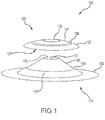
- Dual-reflector ACL 100 may comprise a light source 110, a primary reflector 120, and a secondary reflector 130.
- Light source 110 may comprise any device capable of emitting light.
- light source 110 may comprise a single light emitting diode ("LED").
- the dual-reflector ACL 100 may reflect light from a single LED sufficiently powerful to meet FAA requirements, unlike some prior ACLs which required multiple light sources.
- light source 110 may comprise a plurality of LEDs.
- light source 110 may emit white and/or red light and/or infrared light. It will be appreciated that the color and/or intensity of light source 110 may be adjusted to meet FAA requirements or other military requirements.
- Primary reflector 120 may comprise a dish-shaped reflector, with a concave side 121 of primary reflector 120 facing light source 110 and secondary reflector 130.
- the concave side 121 may comprise a converging or collimating mirror.
- primary reflector 120 may be positioned such that light source 110 is located at a focus of primary reflector 120.
- primary reflector 120 may be a parabolic or spherical reflector.
- the shape of primary reflector 120 may be mathematically calculated in order to reflect light emitted from light source 110 in a desired pattern.
- primary reflector 120 may comprise a mirror.
- primary reflector 120 may comprise a mirrored coating deposited on a surface of a cover lens.
- primary reflector 120 may comprise an exterior reflective ring 122, an interior reflective ring 124, a central reflector 126, and a lens 128.
- central reflector 126 may be located at a vertex of primary reflector 120.
- Central reflector 126 may be configured to reflect light from light source 110 to reflective base 132 of secondary reflector 130.
- interior reflective ring 124 may be adjacent to and circumscribe central reflector 126.
- interior reflective ring 124 may reflect light from light source 110 to an upper portion 136 of a reflective cone 131 of secondary reflector 130, wherein upper portion 136 is proximate light source 110.
- lens 128 may be adjacent to and circumscribe interior reflective ring 124.
- lens 128 may comprise a concave lens, such that light from light source 110 which passes through lens 128 diverges.
- exterior reflective ring 122 may be adjacent to and circumscribe lens 128.
- exterior reflective ring 122 may reflect light from light source 110 to a lower portion 134 of a reflective cone 131 of secondary reflector 130.
- secondary reflector 130 may comprise a reflective cone 131 and a reflective base 132.
- reflective cone 131 may comprise a frustoconical shape.
- Reflective cone 131 may comprise upper portion 136 proximate light source 110, and lower portion 134 proximate reflective base 132.
- Light source 110 may be positioned at a top surface 135 of reflective cone 131, wherein top surface is adjacent to upper portion 136 and opposite reflective base 132.
- Light source 110 may emit light rays between the horizontal plane (0 degrees) and the vertical plane (90 degrees). An axis describing the angular reference is shown for ease of illustration.
- dual-reflector ACL 100 may reflect and/or refract the light emitted by light source 110 in order to meet minimum FAA requirements shown in FIG. 5 .
- light source 110 may emit first light rays 210 in the direction of central reflector 126.
- Central reflector 126 may reflect first light rays 210 in the direction of reflective base 132.
- Reflective base 132 may reflect first light rays 210 between 0 degrees to 30 degrees relative to the horizontal plane.
- light source 110 may emit second light rays 220 in the direction of interior reflective ring 124.
- Interior reflective ring 124 may reflect second light rays 220 in the direction of upper portion 136 of reflective cone 131.
- Upper portion 136 may reflect second light rays 220 between 0 degrees and 30 degrees.
- upper portion 136 may reflect second light rays 220 primarily between 0 degrees and 5 degrees. As used herein, "primarily" refers to greater than 75% of the luminous flux being reflected within the described range.
- light source 110 may emit third light rays 230 in the direction of lens 128.
- Lens 128 may refract third light rays 230 between 0 degrees and 90 degrees.
- lens may refract third light rays 230 primarily between 30 degrees and 75 degrees.
- light source 110 may emit fourth light rays 240 in the direction of exterior reflective ring 122.
- Exterior reflective ring 122 may reflect fourth light rays 240 in the direction of lower portion 134 of reflective cone 131.
- Lower portion 134 may reflect fourth light rays 240 between 0 degrees and 30 degrees. In various embodiments, lower portion 134 may reflect fourth light rays 240 primarily between 5 degrees and 10 degrees.
- light source 110 may emit fifth light rays 250 between 0 degrees and 30 degrees.
- primary reflector 120 may be positioned such that primary reflector 120 extends between 30 degrees and 90 degrees. Thus, between 0 degrees and 30 degrees, fifth light rays 250 may be emitted from dual-reflector ACL without reflection or refraction from primary reflector 120 or secondary reflector 130.
- a “combined angle” refers to a range of angles in which light rays are primarily emitted from dual-reflector ACL 100 after the light rays interact with the components forming the combined angle.
- central reflector 126 and reflective base 132 may form a combined angle of 0 degrees to 30 degrees.
- interior reflective ring 124 and upper portion 136 may form a combined angle of 0 degrees to 10 degrees.
- Lens 128 may form a combined angle of 30 degrees to 75 degrees.
- Exterior reflective ring 122 and lower portion 134 may form a combined angle of 0 degrees to 10 degrees.
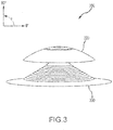
- dual-reflector ACL 300 with a 90 degree primary reflector 320 is illustrated according to various embodiments.
- dual-reflector ACL 300 may comprise a light source, a primary reflector 320, and a secondary reflector 330.
- primary reflector 320 may be positioned such that primary reflector 320 extends between 0 degrees and 90 degrees.
- the light source does not emit light rays which are in turn emitted from dual-reflector ACL 300 without interacting with at least one of primary reflector 320 and secondary reflector 330.
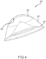
- a dual reflector ACL 400 with a protective cover lens 450 is illustrated according to various embodiments.
- a cover lens 450 may be injection molded.
- Cover lens 450 may be formed to snap onto or otherwise couple with reflective base 432.
- Primary reflector 420 may be coated on an inner surface 452 of cover lens 450.
- a graph illustrating the effective intensity of a dual reflector ACL versus angle from horizontal is illustrated according to various embodiments.
- the minimum intensity required by the FAA is greatest from 0 degrees to 5 degrees, and decreases in steps up to 75 degrees.
- Two dual-reflector ACLs were simulated, one with a cover lens and one without a cover lens.
- the light source in each dual-reflector ACL was a 1500 effective lumen LED.
- both dual-reflector ACLs output sufficient effective intensity to meet the FAA requirements.
- the dual-reflector ACLs output over 400 effective candles (Ecd); from 5 degrees to 10 degrees, the dual-reflector ACLs output over 240 Ecd; from 10 degrees to 20 degrees, the dual-reflector ACLs output over 80 Ecd; from 20 degrees to 30 degrees, the dual-reflector ACLs output over 40 Ecd; and from 30 degrees to 75 degrees, the dual-reflector ACLs output over 20 Ecd.
- conventional ACL systems often require light sources of greater than 3000 effective lumen in order to meet the FAA requirements.
- the dual-reflector ACLs were shown to more effectively distribute the light from the light sources than conventional ACL systems.
- references to "one embodiment”, “an embodiment”, “various embodiments”, etc. indicate that the embodiment described may include a particular feature, structure, or characteristic, but every embodiment may not necessarily include the particular feature, structure, or characteristic. Moreover, such phrases are not necessarily referring to the same embodiment. Further, when a particular feature, structure, or characteristic is described in connection with an embodiment, it is submitted that it is within the knowledge of one skilled in the art to affect such feature, structure, or characteristic in connection with other embodiments whether or not explicitly described. After reading the description, it will be apparent to one skilled in the relevant art(s) how to implement the disclosure in alternative embodiments.
Landscapes
- Engineering & Computer Science (AREA)
- General Engineering & Computer Science (AREA)
- Aviation & Aerospace Engineering (AREA)
- Non-Portable Lighting Devices Or Systems Thereof (AREA)
Claims (6)
- Leuchtsystem, umfassend:eine Lichtquelle (110);einen schüsselförmigen Primärreflektor (120; 320; 420), der dazu konfiguriert ist, Licht von der Lichtquelle (110) aufzufangen; undeinen Sekundärreflektor (130; 330), umfassend einen reflektierenden Kegel (131);dadurch gekennzeichnet, dass der Primärreflektor (120; 320; 420) dazu konfiguriert ist, das Licht von der Lichtquelle (110) zum Sekundärreflektor (130; 330) hin zu reflektieren;wobei der Sekundärreflektor (130; 330) dazu konfiguriert ist, das Licht derart zu reflektieren, dass das Lichtsystem gemessen von 0 Grad in der horizontalen Ebene bis 90 Grad in der vertikalen Ebene eine effektive Stärke von wenigstens 400 effektiven Candela (Ecd) von 0 Grad bis 5 Grad, wenigstens 240 Ecd von 5 Grad bis 10 Grad, wenigstens 80 Ecd von 10 Grad bis 20 Grad, wenigstens 40 Ecd von 20 Grad bis 30 Grad und wenigstens 20 Ecd von 30 Grad bis 75 Grad ausgibt.
- Leuchtsystem nach Anspruch 1, wobei der Primärreflektor (120; 320; 420) einen Zentralreflektor (126) umfasst, wobei der Zentralreflektor (126) dazu konfiguriert ist, Lichtstrahlen von der Lichtquelle (110) zu einer reflektierenden Basis (132; 432) des Sekundärreflektors (130; 330) hin zu reflektieren, und wobei die reflektierende Basis (132; 432) dazu konfiguriert ist, die Lichtstrahlen hauptsächlich zwischen 0 Grad und 30 Grad zu reflektieren.
- Leuchtsystem nach Anspruch 1 oder 2, wobei der Primärreflektor (120; 320; 420) einen inneren reflektierenden Ring (124) umfasst, wobei der innere reflektierende Ring (124) dazu konfiguriert ist, Lichtstrahlen von der Lichtquelle (110) zu einem oberen Abschnitt (136) des reflektierenden Kegels (131) zu reflektieren, und wobei der obere Abschnitt (136) des reflektierenden Kegels (131) dazu konfiguriert ist, Lichtstrahlen hauptsächlich zwischen 0 Grad und 10 Grad zu reflektieren.
- Leuchtsystem nach Anspruch 1, 2 oder 3, wobei der Primärreflektor (120; 320; 420) eine Linse (128) umfasst, und wobei die Linse (128) dazu konfiguriert ist, Lichtstrahlen von der Lichtquelle (110) hauptsächlich zwischen 30 Grad und 75 Grad zu reflektieren.
- Leuchtsystem nach Anspruch 1 bis 4, wobei die Lichtquelle (110) dazu konfiguriert ist, Lichtstrahlen zwischen 0 Grad und 30 Grad abzustrahlen, die nicht mit dem Primärreflektor (120; 320; 420) oder dem Sekundärreflektor (130; 330) interagieren.
- Leuchtsystem nach einem der Ansprüche 1 bis 5, wobei die Lichtquelle (110) weniger als 1500 effektive Lumen insgesamt ausgibt.
Applications Claiming Priority (2)
| Application Number | Priority Date | Filing Date | Title |
|---|---|---|---|
| US14/218,798 US9279562B2 (en) | 2014-03-18 | 2014-03-18 | Systems and methods for anti-collision lights |
| EP15157840.8A EP2921411B1 (de) | 2014-03-18 | 2015-03-05 | Antikollisionsleuchte und leuchtsystem |
Related Parent Applications (2)
| Application Number | Title | Priority Date | Filing Date |
|---|---|---|---|
| EP15157840.8A Division-Into EP2921411B1 (de) | 2014-03-18 | 2015-03-05 | Antikollisionsleuchte und leuchtsystem |
| EP15157840.8A Division EP2921411B1 (de) | 2014-03-18 | 2015-03-05 | Antikollisionsleuchte und leuchtsystem |
Publications (2)
| Publication Number | Publication Date |
|---|---|
| EP3135590A1 EP3135590A1 (de) | 2017-03-01 |
| EP3135590B1 true EP3135590B1 (de) | 2018-05-09 |
Family
ID=52780368
Family Applications (2)
| Application Number | Title | Priority Date | Filing Date |
|---|---|---|---|
| EP16191551.7A Active EP3135590B1 (de) | 2014-03-18 | 2015-03-05 | Systeme und verfahren für antikollisionsleuchten |
| EP15157840.8A Active EP2921411B1 (de) | 2014-03-18 | 2015-03-05 | Antikollisionsleuchte und leuchtsystem |
Family Applications After (1)
| Application Number | Title | Priority Date | Filing Date |
|---|---|---|---|
| EP15157840.8A Active EP2921411B1 (de) | 2014-03-18 | 2015-03-05 | Antikollisionsleuchte und leuchtsystem |
Country Status (2)
| Country | Link |
|---|---|
| US (1) | US9279562B2 (de) |
| EP (2) | EP3135590B1 (de) |
Families Citing this family (3)
| Publication number | Priority date | Publication date | Assignee | Title |
|---|---|---|---|---|
| EP3476745B1 (de) | 2017-10-24 | 2020-10-07 | Goodrich Lighting Systems GmbH | Flugzeugleuchte und dazugehoeriges flugzeug |
| KR102020862B1 (ko) * | 2017-12-13 | 2019-10-18 | (주)대한엔지니어링 | 하향 주사식 다중 적층형 등명기 |
| US11006500B1 (en) * | 2020-01-17 | 2021-05-11 | B/E Aerospace, Inc. | End of life detection system for aircraft anti-collision light |
Family Cites Families (9)
| Publication number | Priority date | Publication date | Assignee | Title |
|---|---|---|---|---|
| GB763376A (en) | 1954-05-11 | 1956-12-12 | Reinhard Paul Henry Hinds | Improvements relating to vehicle lamps |
| US4096555A (en) | 1976-10-28 | 1978-06-20 | Wylain, Inc. | Lighting fixtures |
| US5105347A (en) * | 1991-05-02 | 1992-04-14 | Ruud Lighting, Inc. | Bollard luminaire |
| US7029150B2 (en) | 2004-01-23 | 2006-04-18 | Guide Corporation | Catadioptric light distribution system |
| US7755515B2 (en) * | 2007-01-03 | 2010-07-13 | Riley Hagan | Apparatus and method for preventing night blindness and/or vertigo among pilots caused by the reflection of an aircraft's anti-collision warning lights from clouds or other light reflecting conditions into the cockpit |
| US8303139B1 (en) * | 2010-07-06 | 2012-11-06 | Ohm, Inc. | Illuminator device having multiple reflective surfaces |
| KR20130032110A (ko) * | 2011-09-22 | 2013-04-01 | 삼성전자주식회사 | 조명 장치 |
| EP2667087B1 (de) * | 2012-05-24 | 2014-10-15 | Goodrich Lighting Systems GmbH | Raumschiff-Bodenmanöverlicht |
| ITRM20120265A1 (it) * | 2012-06-07 | 2013-12-08 | Consiglio Nazionale Ricerche | Dispositivo di illuminazione comprendente una schiera di sorgenti optoelettroniche |
-
2014
- 2014-03-18 US US14/218,798 patent/US9279562B2/en active Active
-
2015
- 2015-03-05 EP EP16191551.7A patent/EP3135590B1/de active Active
- 2015-03-05 EP EP15157840.8A patent/EP2921411B1/de active Active
Non-Patent Citations (1)
| Title |
|---|
| None * |
Also Published As
| Publication number | Publication date |
|---|---|
| US9279562B2 (en) | 2016-03-08 |
| US20150267893A1 (en) | 2015-09-24 |
| EP2921411B1 (de) | 2016-11-30 |
| EP2921411A1 (de) | 2015-09-23 |
| EP3135590A1 (de) | 2017-03-01 |
Similar Documents
| Publication | Publication Date | Title |
|---|---|---|
| US8454212B2 (en) | Anti-collision light for aircraft | |
| EP2386045B1 (de) | Lichtquelle mit leds, lichtleiter und reflektor | |
| EP2800697B1 (de) | Led-signalleuchte mit sichtbarer infrarotemission | |
| WO2009059125A1 (en) | Led light module for omnidirectional luminaire | |
| TW201315928A (zh) | 具有清晰視場角之以發光二極體為基礎之光源 | |
| EP2726781B1 (de) | Lichtführung | |
| US9151461B1 (en) | Lens for a vehicular lamp | |
| EP3135590B1 (de) | Systeme und verfahren für antikollisionsleuchten | |
| US10246199B2 (en) | Lighting device for aircraft allowing the integration of additional functions at its center | |
| US20120008327A1 (en) | Tailored side-emitter perimeter beacon | |
| EP2985228B1 (de) | Außenbeleuchtungseinheit für ein Flugzeug und Flugzeug damit | |
| EP2726780B1 (de) | Lichtführung | |
| CA2905246C (en) | Optical system for a directional lamp | |
| CN107202302B (zh) | 飞机防撞灯 | |
| CN109952250A (zh) | 具有静态功能转换的多功能航空器着陆灯 | |
| JP6858015B2 (ja) | 照明器 | |
| US10654591B2 (en) | Precision approach path indicator with a novel reflector arrangement | |
| US10435174B2 (en) | Optical device for lighting and/or signaling light for aircraft and light comprising such an optical device | |
| US20160069529A1 (en) | Exterior signaling and/or illuminating light and corresponding signaling and/or illuminating system |
Legal Events
| Date | Code | Title | Description |
|---|---|---|---|
| PUAI | Public reference made under article 153(3) epc to a published international application that has entered the european phase |
Free format text: ORIGINAL CODE: 0009012 |
|
| STAA | Information on the status of an ep patent application or granted ep patent |
Free format text: STATUS: THE APPLICATION HAS BEEN PUBLISHED |
|
| AC | Divisional application: reference to earlier application |
Ref document number: 2921411 Country of ref document: EP Kind code of ref document: P |
|
| AK | Designated contracting states |
Kind code of ref document: A1 Designated state(s): AL AT BE BG CH CY CZ DE DK EE ES FI FR GB GR HR HU IE IS IT LI LT LU LV MC MK MT NL NO PL PT RO RS SE SI SK SM TR |
|
| STAA | Information on the status of an ep patent application or granted ep patent |
Free format text: STATUS: REQUEST FOR EXAMINATION WAS MADE |
|
| 17P | Request for examination filed |
Effective date: 20170830 |
|
| RBV | Designated contracting states (corrected) |
Designated state(s): AL AT BE BG CH CY CZ DE DK EE ES FI FR GB GR HR HU IE IS IT LI LT LU LV MC MK MT NL NO PL PT RO RS SE SI SK SM TR |
|
| GRAP | Despatch of communication of intention to grant a patent |
Free format text: ORIGINAL CODE: EPIDOSNIGR1 |
|
| STAA | Information on the status of an ep patent application or granted ep patent |
Free format text: STATUS: GRANT OF PATENT IS INTENDED |
|
| INTG | Intention to grant announced |
Effective date: 20171117 |
|
| GRAS | Grant fee paid |
Free format text: ORIGINAL CODE: EPIDOSNIGR3 |
|
| GRAA | (expected) grant |
Free format text: ORIGINAL CODE: 0009210 |
|
| STAA | Information on the status of an ep patent application or granted ep patent |
Free format text: STATUS: THE PATENT HAS BEEN GRANTED |
|
| AC | Divisional application: reference to earlier application |
Ref document number: 2921411 Country of ref document: EP Kind code of ref document: P |
|
| AK | Designated contracting states |
Kind code of ref document: B1 Designated state(s): AL AT BE BG CH CY CZ DE DK EE ES FI FR GB GR HR HU IE IS IT LI LT LU LV MC MK MT NL NO PL PT RO RS SE SI SK SM TR |
|
| REG | Reference to a national code |
Ref country code: GB Ref legal event code: FG4D |
|
| REG | Reference to a national code |
Ref country code: CH Ref legal event code: EP Ref country code: AT Ref legal event code: REF Ref document number: 997372 Country of ref document: AT Kind code of ref document: T Effective date: 20180515 |
|
| REG | Reference to a national code |
Ref country code: IE Ref legal event code: FG4D |
|
| REG | Reference to a national code |
Ref country code: DE Ref legal event code: R096 Ref document number: 602015011047 Country of ref document: DE |
|
| REG | Reference to a national code |
Ref country code: NL Ref legal event code: MP Effective date: 20180509 |
|
| REG | Reference to a national code |
Ref country code: LT Ref legal event code: MG4D |
|
| PG25 | Lapsed in a contracting state [announced via postgrant information from national office to epo] |
Ref country code: NO Free format text: LAPSE BECAUSE OF FAILURE TO SUBMIT A TRANSLATION OF THE DESCRIPTION OR TO PAY THE FEE WITHIN THE PRESCRIBED TIME-LIMIT Effective date: 20180809 Ref country code: FI Free format text: LAPSE BECAUSE OF FAILURE TO SUBMIT A TRANSLATION OF THE DESCRIPTION OR TO PAY THE FEE WITHIN THE PRESCRIBED TIME-LIMIT Effective date: 20180509 Ref country code: BG Free format text: LAPSE BECAUSE OF FAILURE TO SUBMIT A TRANSLATION OF THE DESCRIPTION OR TO PAY THE FEE WITHIN THE PRESCRIBED TIME-LIMIT Effective date: 20180809 Ref country code: ES Free format text: LAPSE BECAUSE OF FAILURE TO SUBMIT A TRANSLATION OF THE DESCRIPTION OR TO PAY THE FEE WITHIN THE PRESCRIBED TIME-LIMIT Effective date: 20180509 Ref country code: SE Free format text: LAPSE BECAUSE OF FAILURE TO SUBMIT A TRANSLATION OF THE DESCRIPTION OR TO PAY THE FEE WITHIN THE PRESCRIBED TIME-LIMIT Effective date: 20180509 Ref country code: LT Free format text: LAPSE BECAUSE OF FAILURE TO SUBMIT A TRANSLATION OF THE DESCRIPTION OR TO PAY THE FEE WITHIN THE PRESCRIBED TIME-LIMIT Effective date: 20180509 |
|
| PG25 | Lapsed in a contracting state [announced via postgrant information from national office to epo] |
Ref country code: LV Free format text: LAPSE BECAUSE OF FAILURE TO SUBMIT A TRANSLATION OF THE DESCRIPTION OR TO PAY THE FEE WITHIN THE PRESCRIBED TIME-LIMIT Effective date: 20180509 Ref country code: NL Free format text: LAPSE BECAUSE OF FAILURE TO SUBMIT A TRANSLATION OF THE DESCRIPTION OR TO PAY THE FEE WITHIN THE PRESCRIBED TIME-LIMIT Effective date: 20180509 Ref country code: HR Free format text: LAPSE BECAUSE OF FAILURE TO SUBMIT A TRANSLATION OF THE DESCRIPTION OR TO PAY THE FEE WITHIN THE PRESCRIBED TIME-LIMIT Effective date: 20180509 Ref country code: RS Free format text: LAPSE BECAUSE OF FAILURE TO SUBMIT A TRANSLATION OF THE DESCRIPTION OR TO PAY THE FEE WITHIN THE PRESCRIBED TIME-LIMIT Effective date: 20180509 Ref country code: GR Free format text: LAPSE BECAUSE OF FAILURE TO SUBMIT A TRANSLATION OF THE DESCRIPTION OR TO PAY THE FEE WITHIN THE PRESCRIBED TIME-LIMIT Effective date: 20180810 |
|
| REG | Reference to a national code |
Ref country code: AT Ref legal event code: MK05 Ref document number: 997372 Country of ref document: AT Kind code of ref document: T Effective date: 20180509 |
|
| PG25 | Lapsed in a contracting state [announced via postgrant information from national office to epo] |
Ref country code: DK Free format text: LAPSE BECAUSE OF FAILURE TO SUBMIT A TRANSLATION OF THE DESCRIPTION OR TO PAY THE FEE WITHIN THE PRESCRIBED TIME-LIMIT Effective date: 20180509 Ref country code: AT Free format text: LAPSE BECAUSE OF FAILURE TO SUBMIT A TRANSLATION OF THE DESCRIPTION OR TO PAY THE FEE WITHIN THE PRESCRIBED TIME-LIMIT Effective date: 20180509 Ref country code: PL Free format text: LAPSE BECAUSE OF FAILURE TO SUBMIT A TRANSLATION OF THE DESCRIPTION OR TO PAY THE FEE WITHIN THE PRESCRIBED TIME-LIMIT Effective date: 20180509 Ref country code: EE Free format text: LAPSE BECAUSE OF FAILURE TO SUBMIT A TRANSLATION OF THE DESCRIPTION OR TO PAY THE FEE WITHIN THE PRESCRIBED TIME-LIMIT Effective date: 20180509 Ref country code: RO Free format text: LAPSE BECAUSE OF FAILURE TO SUBMIT A TRANSLATION OF THE DESCRIPTION OR TO PAY THE FEE WITHIN THE PRESCRIBED TIME-LIMIT Effective date: 20180509 Ref country code: CZ Free format text: LAPSE BECAUSE OF FAILURE TO SUBMIT A TRANSLATION OF THE DESCRIPTION OR TO PAY THE FEE WITHIN THE PRESCRIBED TIME-LIMIT Effective date: 20180509 Ref country code: SK Free format text: LAPSE BECAUSE OF FAILURE TO SUBMIT A TRANSLATION OF THE DESCRIPTION OR TO PAY THE FEE WITHIN THE PRESCRIBED TIME-LIMIT Effective date: 20180509 |
|
| REG | Reference to a national code |
Ref country code: CH Ref legal event code: PK Free format text: BERICHTIGUNGEN |
|
| REG | Reference to a national code |
Ref country code: DE Ref legal event code: R097 Ref document number: 602015011047 Country of ref document: DE |
|
| RIC2 | Information provided on ipc code assigned after grant |
Ipc: B64D 47/06 20060101AFI20161201BHEP Ipc: F21S 8/10 20060101ALI20161201BHEP |
|
| PG25 | Lapsed in a contracting state [announced via postgrant information from national office to epo] |
Ref country code: SM Free format text: LAPSE BECAUSE OF FAILURE TO SUBMIT A TRANSLATION OF THE DESCRIPTION OR TO PAY THE FEE WITHIN THE PRESCRIBED TIME-LIMIT Effective date: 20180509 Ref country code: IT Free format text: LAPSE BECAUSE OF FAILURE TO SUBMIT A TRANSLATION OF THE DESCRIPTION OR TO PAY THE FEE WITHIN THE PRESCRIBED TIME-LIMIT Effective date: 20180509 |
|
| PLBE | No opposition filed within time limit |
Free format text: ORIGINAL CODE: 0009261 |
|
| STAA | Information on the status of an ep patent application or granted ep patent |
Free format text: STATUS: NO OPPOSITION FILED WITHIN TIME LIMIT |
|
| 26N | No opposition filed |
Effective date: 20190212 |
|
| PG25 | Lapsed in a contracting state [announced via postgrant information from national office to epo] |
Ref country code: SI Free format text: LAPSE BECAUSE OF FAILURE TO SUBMIT A TRANSLATION OF THE DESCRIPTION OR TO PAY THE FEE WITHIN THE PRESCRIBED TIME-LIMIT Effective date: 20180509 |
|
| PG25 | Lapsed in a contracting state [announced via postgrant information from national office to epo] |
Ref country code: MC Free format text: LAPSE BECAUSE OF FAILURE TO SUBMIT A TRANSLATION OF THE DESCRIPTION OR TO PAY THE FEE WITHIN THE PRESCRIBED TIME-LIMIT Effective date: 20180509 |
|
| REG | Reference to a national code |
Ref country code: CH Ref legal event code: PL |
|
| PG25 | Lapsed in a contracting state [announced via postgrant information from national office to epo] |
Ref country code: AL Free format text: LAPSE BECAUSE OF FAILURE TO SUBMIT A TRANSLATION OF THE DESCRIPTION OR TO PAY THE FEE WITHIN THE PRESCRIBED TIME-LIMIT Effective date: 20180509 Ref country code: LU Free format text: LAPSE BECAUSE OF NON-PAYMENT OF DUE FEES Effective date: 20190305 |
|
| REG | Reference to a national code |
Ref country code: BE Ref legal event code: MM Effective date: 20190331 |
|
| PG25 | Lapsed in a contracting state [announced via postgrant information from national office to epo] |
Ref country code: CH Free format text: LAPSE BECAUSE OF NON-PAYMENT OF DUE FEES Effective date: 20190331 Ref country code: LI Free format text: LAPSE BECAUSE OF NON-PAYMENT OF DUE FEES Effective date: 20190331 Ref country code: IE Free format text: LAPSE BECAUSE OF NON-PAYMENT OF DUE FEES Effective date: 20190305 |
|
| PG25 | Lapsed in a contracting state [announced via postgrant information from national office to epo] |
Ref country code: BE Free format text: LAPSE BECAUSE OF NON-PAYMENT OF DUE FEES Effective date: 20190331 |
|
| PG25 | Lapsed in a contracting state [announced via postgrant information from national office to epo] |
Ref country code: TR Free format text: LAPSE BECAUSE OF FAILURE TO SUBMIT A TRANSLATION OF THE DESCRIPTION OR TO PAY THE FEE WITHIN THE PRESCRIBED TIME-LIMIT Effective date: 20180509 |
|
| PG25 | Lapsed in a contracting state [announced via postgrant information from national office to epo] |
Ref country code: MT Free format text: LAPSE BECAUSE OF NON-PAYMENT OF DUE FEES Effective date: 20190305 Ref country code: PT Free format text: LAPSE BECAUSE OF FAILURE TO SUBMIT A TRANSLATION OF THE DESCRIPTION OR TO PAY THE FEE WITHIN THE PRESCRIBED TIME-LIMIT Effective date: 20180910 |
|
| PG25 | Lapsed in a contracting state [announced via postgrant information from national office to epo] |
Ref country code: CY Free format text: LAPSE BECAUSE OF FAILURE TO SUBMIT A TRANSLATION OF THE DESCRIPTION OR TO PAY THE FEE WITHIN THE PRESCRIBED TIME-LIMIT Effective date: 20180509 |
|
| PG25 | Lapsed in a contracting state [announced via postgrant information from national office to epo] |
Ref country code: IS Free format text: LAPSE BECAUSE OF FAILURE TO SUBMIT A TRANSLATION OF THE DESCRIPTION OR TO PAY THE FEE WITHIN THE PRESCRIBED TIME-LIMIT Effective date: 20180909 |
|
| PG25 | Lapsed in a contracting state [announced via postgrant information from national office to epo] |
Ref country code: HU Free format text: LAPSE BECAUSE OF FAILURE TO SUBMIT A TRANSLATION OF THE DESCRIPTION OR TO PAY THE FEE WITHIN THE PRESCRIBED TIME-LIMIT; INVALID AB INITIO Effective date: 20150305 |
|
| PG25 | Lapsed in a contracting state [announced via postgrant information from national office to epo] |
Ref country code: MK Free format text: LAPSE BECAUSE OF FAILURE TO SUBMIT A TRANSLATION OF THE DESCRIPTION OR TO PAY THE FEE WITHIN THE PRESCRIBED TIME-LIMIT Effective date: 20180509 |
|
| P01 | Opt-out of the competence of the unified patent court (upc) registered |
Effective date: 20230522 |
|
| REG | Reference to a national code |
Ref country code: DE Ref legal event code: R081 Ref document number: 602015011047 Country of ref document: DE Owner name: GOODRICH LIGHTING SYSTEMS, INC. (N.D.GES.D.STA, US Free format text: FORMER OWNER: GOODRICH CORPORATION, CHARLOTTE, N.C., US |
|
| PGFP | Annual fee paid to national office [announced via postgrant information from national office to epo] |
Ref country code: DE Payment date: 20250218 Year of fee payment: 11 |
|
| PGFP | Annual fee paid to national office [announced via postgrant information from national office to epo] |
Ref country code: FR Payment date: 20250218 Year of fee payment: 11 |
|
| PGFP | Annual fee paid to national office [announced via postgrant information from national office to epo] |
Ref country code: GB Payment date: 20250221 Year of fee payment: 11 |