EP3135519A1 - Tarpaulin carriage and fastening mechanism for dumpers - Google Patents
Tarpaulin carriage and fastening mechanism for dumpers Download PDFInfo
- Publication number
- EP3135519A1 EP3135519A1 EP16185501.0A EP16185501A EP3135519A1 EP 3135519 A1 EP3135519 A1 EP 3135519A1 EP 16185501 A EP16185501 A EP 16185501A EP 3135519 A1 EP3135519 A1 EP 3135519A1
- Authority
- EP
- European Patent Office
- Prior art keywords
- tarpaulin
- dumper
- console
- supporting
- mounting
- Prior art date
- Legal status (The legal status is an assumption and is not a legal conclusion. Google has not performed a legal analysis and makes no representation as to the accuracy of the status listed.)
- Withdrawn
Links
- 230000007246 mechanism Effects 0.000 title claims abstract description 24
- 238000005096 rolling process Methods 0.000 claims description 12
- 230000002411 adverse Effects 0.000 claims description 3
- 239000000428 dust Substances 0.000 claims description 3
- 238000010586 diagram Methods 0.000 description 9
- 238000007689 inspection Methods 0.000 description 5
- 238000009412 basement excavation Methods 0.000 description 2
- 239000004035 construction material Substances 0.000 description 2
- 230000000737 periodic effect Effects 0.000 description 2
- 230000006872 improvement Effects 0.000 description 1
- 230000004048 modification Effects 0.000 description 1
- 238000012986 modification Methods 0.000 description 1
Images

Classifications
-
- B—PERFORMING OPERATIONS; TRANSPORTING
- B60—VEHICLES IN GENERAL
- B60J—WINDOWS, WINDSCREENS, NON-FIXED ROOFS, DOORS, OR SIMILAR DEVICES FOR VEHICLES; REMOVABLE EXTERNAL PROTECTIVE COVERINGS SPECIALLY ADAPTED FOR VEHICLES
- B60J7/00—Non-fixed roofs; Roofs with movable panels, e.g. rotary sunroofs
- B60J7/08—Non-fixed roofs; Roofs with movable panels, e.g. rotary sunroofs of non-sliding type, i.e. movable or removable roofs or panels, e.g. let-down tops or roofs capable of being easily detached or of assuming a collapsed or inoperative position
- B60J7/085—Non-fixed roofs; Roofs with movable panels, e.g. rotary sunroofs of non-sliding type, i.e. movable or removable roofs or panels, e.g. let-down tops or roofs capable of being easily detached or of assuming a collapsed or inoperative position winding up, e.g. for utility vehicles
Definitions
- Present invention relates to a tarpaulin carriage and fastening mechanism for half pipe truck dumpers and semi-trailer dumpers that are used for carrying construction materials, excavation debris, demolition debris or mine ores on highways or off the road.
- Present invention particularly relates to a new constructive structure allowing tarpaulins of half pipe dumpers that are used for carrying construction materials, excavation debris, demolition debris or mine ores on highways or off the road to be supported on the vehicle in compliance with the laws and regulations.
- Tarpaulin mechanisms that are attached along the sides of dumpers are in highest demand in European and Russian markets.
- "L" shaped supports are welded, riveted or bolted to the top of the dumper body to carry tarpaulin mechanisms.
- the width of the vehicle exceeds the maximum allowed vehicle width of 2550 mm. Therefore, these vehicles fail to conform to the regulations.
- welded tarpaulin supports are cut and then re-welded and bolted supports are removed and then reinstalled following the inspection. When welded type tarpaulin supports are damaged, it is not possible to replace them without modifying the structure.
- present invention aims at eliminating above mentioned problems.
- One of the objectives of present invention is to make sure that the tarpaulin is supported in compliance with the regulations.
- One other objective of present invention is to eliminate the need to remove or cut supporting consoles prior to periodic motor vehicle inspections.
- Another objective of present invention is to make it possible to install replacement tarpaulin supports following damage without the need for any modification.
- a tarpaulin carriage and fastening mechanism for half pipe truck dumpers and semi-trailer dumpers that are used for carrying cargo, attaching the tarpaulin to the dumper and being supported by the dumper, incorporating following components, is developed to fulfill above mentioned objectives;
- the tarpaulin carriage and fastening mechanism also incorporates following components:
- the tarpaulin rolling mechanism on which the tarpaulin (3), that is used to cover the dumper body with a view to protect the cargo on the dumper body against adverse weather conditions such as rain, snow or dust, is rolled to be supported on the dumper (1), as required, incorporates following components:
- the tarpaulin carriage and fastening mechanism constituting the subject of present invention operates as follows: Under normal operation, i.e. in cases where the vehicle is not scheduled for motor vehicle inspection, tarpaulin supporting console (4) is located outside the dumper (1).
- the mount (8) preferably in the form of a hook is located in a way to pass through the mounting duct (44).
- Supporting console fastener (5) which is a cable that is preferably tensioned, passes through it.
- the mounting lug (43), on which the mounting duct is formed (44), and consequently the tarpaulin supporting console (4) are fastened to the side of the dumper (1) externally and cannot move.
- the tarpaulin (3) is located inside tarpaulin housing (41).
- supporting console fastener (5) is removed from the mount (8).
- Supporting console fastener (5) is rotated towards the inside of the dumper (1) body. This rotation is made possible by locating the center of the bearing pin (7) inside console mounting bush (42) and the ends of the bearing pin (7) inside bearing bushes (6) that are fastened to the dumper (1). Consequently, tarpaulin supporting console (4) can rotate freely since there is no obstruction preventing rotation in front of the mounting lug (43) once supporting console fastener (5), i.e. the cable, is removed from the mount (8).
- supporting console (4) is located inside the dumper (1) body. Therefore the tarpaulin (3) is carried in compliance with the regulations.
Landscapes
- Engineering & Computer Science (AREA)
- Mechanical Engineering (AREA)
- Handcart (AREA)
- Load-Engaging Elements For Cranes (AREA)
Abstract
Present invention relates to a tarpaulin carriage and fastening mechanism for half pipe truck dumpers (1) and semi-trailer dumpers (1) that are used for carrying cargo, attaching the tarpaulin to the dumper (1) and supporting it on the dumper (1), incorporating following components that allow the tarpaulin supporting console (4) to rotate and to be attached to the dumper (1); console mounting bushes (42) attached to the tarpaulin housing (41), bearing bushes (6) fastened to the dumper (1), a bearing pin located inside the said bearing bushes (6) and console mounting bushes (42), attaching them to each other.
Description
- Present invention relates to a tarpaulin carriage and fastening mechanism for half pipe truck dumpers and semi-trailer dumpers that are used for carrying construction materials, excavation debris, demolition debris or mine ores on highways or off the road.
- Present invention particularly relates to a new constructive structure allowing tarpaulins of half pipe dumpers that are used for carrying construction materials, excavation debris, demolition debris or mine ores on highways or off the road to be supported on the vehicle in compliance with the laws and regulations.
- Tarpaulin mechanisms that are attached along the sides of dumpers are in highest demand in European and Russian markets. However, "L" shaped supports are welded, riveted or bolted to the top of the dumper body to carry tarpaulin mechanisms. When this structure is incorporated, the width of the vehicle exceeds the maximum allowed vehicle width of 2550 mm. Therefore, these vehicles fail to conform to the regulations. In order to avoid any problems during the periodic motor vehicle inspections, welded tarpaulin supports are cut and then re-welded and bolted supports are removed and then reinstalled following the inspection. When welded type tarpaulin supports are damaged, it is not possible to replace them without modifying the structure.
- Consequently, it is deemed necessary to introduce an improvement in the technical field due to above mentioned problems, considering that solutions that are currently available are inadequate.
- Inspired by the state of the art, present invention aims at eliminating above mentioned problems.
- One of the objectives of present invention is to make sure that the tarpaulin is supported in compliance with the regulations.
- One other objective of present invention is to eliminate the need to remove or cut supporting consoles prior to periodic motor vehicle inspections.
- Another objective of present invention is to make it possible to install replacement tarpaulin supports following damage without the need for any modification.
- Consequently, a tarpaulin carriage and fastening mechanism for half pipe truck dumpers and semi-trailer dumpers that are used for carrying cargo, attaching the tarpaulin to the dumper and being supported by the dumper, incorporating following components, is developed to fulfill above mentioned objectives;
- a tarpaulin rolling mechanism on which the tarpaulin, that is used to cover the dumper body with a view to protect the cargo on the dumper body against adverse weather conditions such as rain, snow or dust, is rolled to be supported on the dumper, as required,
- a tarpaulin supporting console allowing the tarpaulin and tarpaulin rolling mechanism to be supported together in rolled form on the dumper,
- a tarpaulin housing located on the said tarpaulin supporting console, inside of which the tarpaulin rolled on the tarpaulin rolling mechanism is located,
- a mounting duct located on the mounting lug of the tarpaulin supporting console,
- a mount located inside the mounting duct in cases where the tarpaulin supporting console is located outside the dumper,
- a supporting console fastener passing through the mount, fastening the tarpaulin supporting console vertically in place.
- The tarpaulin carriage and fastening mechanism also incorporates following components:
- following components that help the tarpaulin supporting console to rotate and to be attached to the dumper:
- o console mounting bushes fastened to the tarpaulin housing,
- o bearing bushes mounted to the dumper,
- o bearing pin located inside the said bearing bushes and console mounting bushes, attaching them to each other.
- Structural and characteristic features of present invention as well as all advantages thereof can be understood clearly with the help of following diagrams and detailed descriptions providing reference to these diagrams and thus assessment of the patent should be made by reading this application together with this diagram and detailed description.
-
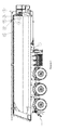
- Diagram 1, two dimensional side views of a dumper on which the carriage and fastening mechanism constituting the subject of present invention is located.
- Diagram 2, top perspective view of the front of the dumper.
- Diagram 3, bottom perspective view of the front of the dumper.
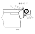
- Diagram 4, detailed section view of the carriage and fastening mechanism constituting the subject of present invention.
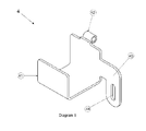
- Diagram 5, perspective view of tarpaulin supporting console.
-
- 1.
- Dumper
- 2.
- Tarpaulin rolling mechanism
- 3.
- Tarpaulin
- 4.
- Tarpaulin supporting console
41. Tarpaulin housing
42. Console mounting bushes
43. Mounting lug
44. Mounting duct - 5.
- Supporting console fastener
- 6.
- Bearing bush
- 7.
- Bearing pin
- 8.
- Mount
- Drawings are not necessarily scaled and details that are not absolutely required to describe present invention might have been omitted. Additionally, components that are substantially identical or that have substantially identical functions are referred to under the same number.
- This detailed description explains preferred structures of the tarpaulin carriage and fastening mechanism constituting the subject of present invention, with the sole purpose of facilitating the comprehension of the subject.
- The tarpaulin rolling mechanism, on which the tarpaulin (3), that is used to cover the dumper body with a view to protect the cargo on the dumper body against adverse weather conditions such as rain, snow or dust, is rolled to be supported on the dumper (1), as required, incorporates following components:
- tarpaulin rolling mechanism (2)
- a tarpaulin supporting console incorporating a tarpaulin housing (41), console mounting bushes (42), mounting lug (43) and mounting duct (44),
- supporting console fastener (5),
- bearing bush (6),
- bearing pin (7),
- mount (8).
- Technical features and functions of above mentioned components are provided here below:
- Tarpaulin rolling mechanism (2), preferably in the form of a tube, is the component on which the tarpaulin (3) is rolled to be supported on the dumper (1).
- Tarpaulin supporting console (4) is the component that allows the tarpaulin (3) and tarpaulin rolling mechanism (2) to be supported together in rolled form on the dumper (1). Tarpaulin supporting console (4) incorporates a tarpaulin housing (41), console mounting bushes (42), mounting lug (43) and mounting duct (44). Tarpaulin housing (41) provides adequate storage space for the tarpaulin (3) rolled on tarpaulin rolling mechanism (2). Console mounting bush (42) is welded to tarpaulin housing (42). Console mounting bush (42) attaches tarpaulin supporting console (4) to the dumper (1) through bearing pin (7) and bearing bush (6). Console mounting bush (42) also helps the tarpaulin supporting console (4) to rotate around the bearing pin (7).
- Preferably in the form of a cable, supporting console fastener (5) passes through the mount (8) to fasten tarpaulin supporting console vertically in place (4).
- Bearing bushes (6) are welded to upper ends of the sides of the dumper (1). Bearing bushes (6) incorporate bearing pins (7). Bearing bushes support tarpaulin supporting console (4) and attach it to the dumper (1) through bearing pins (7).
- Bearing pins (7) help attaching console mounting bushes (42) that are located on tarpaulin supporting console to bearing bushes (6) that are welded to the dumper (1) and rotating console mounting bush (42) and consequently tarpaulin supporting console (4) that is fastened thereto.
- Mounting lug (43) is the component where the mounting duct (44) is formed on tarpaulin supporting console (4). Preferably in the form of a hook, the mount (8) is located inside the mounting duct in cases where the tarpaulin supporting console (4) is located outside the dumper (1).
- The tarpaulin carriage and fastening mechanism constituting the subject of present invention operates as follows: Under normal operation, i.e. in cases where the vehicle is not scheduled for motor vehicle inspection, tarpaulin supporting console (4) is located outside the dumper (1). The mount (8), preferably in the form of a hook is located in a way to pass through the mounting duct (44). Supporting console fastener (5), which is a cable that is preferably tensioned, passes through it. Thus, the mounting lug (43), on which the mounting duct is formed (44), and consequently the tarpaulin supporting console (4) are fastened to the side of the dumper (1) externally and cannot move. The tarpaulin (3) is located inside tarpaulin housing (41). On the other hand, when the vehicle is scheduled for motor vehicle inspection, supporting console fastener (5) is removed from the mount (8). Supporting console fastener (5) is rotated towards the inside of the dumper (1) body. This rotation is made possible by locating the center of the bearing pin (7) inside console mounting bush (42) and the ends of the bearing pin (7) inside bearing bushes (6) that are fastened to the dumper (1). Consequently, tarpaulin supporting console (4) can rotate freely since there is no obstruction preventing rotation in front of the mounting lug (43) once supporting console fastener (5), i.e. the cable, is removed from the mount (8). When rotating operation is completed, supporting console (4) is located inside the dumper (1) body. Therefore the tarpaulin (3) is carried in compliance with the regulations.
Claims (1)
- A tarpaulin carriage and fastening mechanism for half pipe truck dumpers (1) and semi-trailer dumpers (1) that are used for carrying cargo, attaching the tarpaulin to the dumper (1) and supporting it on the dumper (1), incorporating following components;- a tarpaulin rolling mechanism (2) on which the tarpaulin (3), that is used to cover the dumper (1) body with a view to protecting the cargo on the dumper (1) body against adverse weather conditions such as rain, snow or dust, is rolled to be supported on the dumper (1), as required,- a tarpaulin supporting console (4) allowing the tarpaulin (3) and tarpaulin rolling mechanism (2) to be supported together in rolled form on the dumper (1),- a tarpaulin housing (41) located on the said tarpaulin supporting console (4), inside of which the tarpaulin (3) rolled on the tarpaulin rolling mechanism (2) is located,- a mounting duct (44) located on the mounting lug (43) of the tarpaulin supporting console (4),- a mount (8) located inside the mounting duct (44) in cases where the tarpaulin supporting console (4) is located outside the dumper (1),- a supporting console fastener (5) passing through the mount (8), fastening the tarpaulin supporting console (4) vertically in place,- following components that help the tarpaulin supporting console (4) to rotate and to be attached to the dumper (1):o console mounting bushes (42) fastened to the tarpaulin housing (41),o bearing bushes (6) mounted to the dumper (1),o bearing pin (7) located inside said bearing bushes (6) and console mounting bushes (42), attaching them to each other.
Applications Claiming Priority (1)
| Application Number | Priority Date | Filing Date | Title |
|---|---|---|---|
| TR2015/10626A TR201510626A2 (en) | 2015-08-27 | 2015-08-27 | Tarpaulin carrying and fixing device for dampers |
Publications (1)
| Publication Number | Publication Date |
|---|---|
| EP3135519A1 true EP3135519A1 (en) | 2017-03-01 |
Family
ID=56799354
Family Applications (1)
| Application Number | Title | Priority Date | Filing Date |
|---|---|---|---|
| EP16185501.0A Withdrawn EP3135519A1 (en) | 2015-08-27 | 2016-08-24 | Tarpaulin carriage and fastening mechanism for dumpers |
Country Status (2)
| Country | Link |
|---|---|
| EP (1) | EP3135519A1 (en) |
| TR (1) | TR201510626A2 (en) |
Citations (3)
| Publication number | Priority date | Publication date | Assignee | Title |
|---|---|---|---|---|
| US20030052506A1 (en) * | 2000-06-13 | 2003-03-20 | Real Royer | Assembly for covering open top containers |
| US6641199B1 (en) * | 2001-09-14 | 2003-11-04 | W. Glen Hicks | Dual side tarp |
| EP3015301A1 (en) * | 2014-10-31 | 2016-05-04 | Franz Xaver Meiller Fahrzeug- und Maschinenfabrik-GmbH & Co KG | Container with an upper loading opening and tarpaulin covering device and winding support device for a container of this kind |
-
2015
- 2015-08-27 TR TR2015/10626A patent/TR201510626A2/en unknown
-
2016
- 2016-08-24 EP EP16185501.0A patent/EP3135519A1/en not_active Withdrawn
Patent Citations (3)
| Publication number | Priority date | Publication date | Assignee | Title |
|---|---|---|---|---|
| US20030052506A1 (en) * | 2000-06-13 | 2003-03-20 | Real Royer | Assembly for covering open top containers |
| US6641199B1 (en) * | 2001-09-14 | 2003-11-04 | W. Glen Hicks | Dual side tarp |
| EP3015301A1 (en) * | 2014-10-31 | 2016-05-04 | Franz Xaver Meiller Fahrzeug- und Maschinenfabrik-GmbH & Co KG | Container with an upper loading opening and tarpaulin covering device and winding support device for a container of this kind |
Also Published As
| Publication number | Publication date |
|---|---|
| TR201510626A2 (en) | 2015-12-21 |
Similar Documents
| Publication | Publication Date | Title |
|---|---|---|
| EP3049312B1 (en) | Drag reducing device | |
| CN112105553B (en) | Rain shielding device for shipping | |
| US20140312604A1 (en) | Mud Flap System | |
| JP6999512B2 (en) | Turning work vehicle | |
| JP2016179807A (en) | Vehicle with load-carrying platform | |
| EP3135519A1 (en) | Tarpaulin carriage and fastening mechanism for dumpers | |
| CN112839864B (en) | Rain shielding device for ship loading | |
| KR101183700B1 (en) | Camping trailer with a car having cargo box | |
| US5799746A (en) | Underground vehicle safety cab with safety bar | |
| JP2024174076A (en) | Swivel work vehicle | |
| CN208325026U (en) | A kind of electronic cladding system | |
| US8459169B2 (en) | Gunner platform protector | |
| EP2915771A1 (en) | Forklift head-guard structure | |
| JP4770417B2 (en) | Construction machinery platform | |
| CN108583400A (en) | A kind of car body of parallel-moving type rollover dumping lorry | |
| CN112334381A (en) | Track vehicle | |
| RU2379426C2 (en) | Unified excavator | |
| JP2009191524A (en) | Fender for working machine | |
| JP5947190B2 (en) | Undercover support structure of the car body | |
| JP2007261349A (en) | Fuel filter mounting structure | |
| US20250100356A1 (en) | Tarpaulin protection devices | |
| JP7354221B2 (en) | turning work vehicle | |
| WO2016200353A1 (en) | Leveling adaptor | |
| JP5441641B2 (en) | Snow removal vehicle | |
| CN223420593U (en) | Dump truck taillight bracket and dump truck |
Legal Events
| Date | Code | Title | Description |
|---|---|---|---|
| PUAI | Public reference made under article 153(3) epc to a published international application that has entered the european phase |
Free format text: ORIGINAL CODE: 0009012 |
|
| AK | Designated contracting states |
Kind code of ref document: A1 Designated state(s): AL AT BE BG CH CY CZ DE DK EE ES FI FR GB GR HR HU IE IS IT LI LT LU LV MC MK MT NL NO PL PT RO RS SE SI SK SM TR |
|
| AX | Request for extension of the european patent |
Extension state: BA ME |
|
| 17P | Request for examination filed |
Effective date: 20170406 |
|
| 17Q | First examination report despatched |
Effective date: 20180329 |
|
| STAA | Information on the status of an ep patent application or granted ep patent |
Free format text: STATUS: THE APPLICATION IS DEEMED TO BE WITHDRAWN |
|
| 18D | Application deemed to be withdrawn |
Effective date: 20180809 |