EP3135482A1 - Double safety mirror and method of manufacturing thereof - Google Patents
Double safety mirror and method of manufacturing thereof Download PDFInfo
- Publication number
- EP3135482A1 EP3135482A1 EP16171366.4A EP16171366A EP3135482A1 EP 3135482 A1 EP3135482 A1 EP 3135482A1 EP 16171366 A EP16171366 A EP 16171366A EP 3135482 A1 EP3135482 A1 EP 3135482A1
- Authority
- EP
- European Patent Office
- Prior art keywords
- layer
- glue
- plates
- glass material
- painted
- Prior art date
- Legal status (The legal status is an assumption and is not a legal conclusion. Google has not performed a legal analysis and makes no representation as to the accuracy of the status listed.)
- Granted
Links
Images
Classifications
-
- B—PERFORMING OPERATIONS; TRANSPORTING
- B32—LAYERED PRODUCTS
- B32B—LAYERED PRODUCTS, i.e. PRODUCTS BUILT-UP OF STRATA OF FLAT OR NON-FLAT, e.g. CELLULAR OR HONEYCOMB, FORM
- B32B17/00—Layered products essentially comprising sheet glass, or glass, slag, or like fibres
- B32B17/06—Layered products essentially comprising sheet glass, or glass, slag, or like fibres comprising glass as the main or only constituent of a layer, next to another layer of a specific material
- B32B17/10—Layered products essentially comprising sheet glass, or glass, slag, or like fibres comprising glass as the main or only constituent of a layer, next to another layer of a specific material of synthetic resin
- B32B17/10005—Layered products essentially comprising sheet glass, or glass, slag, or like fibres comprising glass as the main or only constituent of a layer, next to another layer of a specific material of synthetic resin laminated safety glass or glazing
- B32B17/10009—Layered products essentially comprising sheet glass, or glass, slag, or like fibres comprising glass as the main or only constituent of a layer, next to another layer of a specific material of synthetic resin laminated safety glass or glazing characterized by the number, the constitution or treatment of glass sheets
- B32B17/10036—Layered products essentially comprising sheet glass, or glass, slag, or like fibres comprising glass as the main or only constituent of a layer, next to another layer of a specific material of synthetic resin laminated safety glass or glazing characterized by the number, the constitution or treatment of glass sheets comprising two outer glass sheets
-
- B—PERFORMING OPERATIONS; TRANSPORTING
- B32—LAYERED PRODUCTS
- B32B—LAYERED PRODUCTS, i.e. PRODUCTS BUILT-UP OF STRATA OF FLAT OR NON-FLAT, e.g. CELLULAR OR HONEYCOMB, FORM
- B32B17/00—Layered products essentially comprising sheet glass, or glass, slag, or like fibres
- B32B17/06—Layered products essentially comprising sheet glass, or glass, slag, or like fibres comprising glass as the main or only constituent of a layer, next to another layer of a specific material
- B32B17/10—Layered products essentially comprising sheet glass, or glass, slag, or like fibres comprising glass as the main or only constituent of a layer, next to another layer of a specific material of synthetic resin
- B32B17/10005—Layered products essentially comprising sheet glass, or glass, slag, or like fibres comprising glass as the main or only constituent of a layer, next to another layer of a specific material of synthetic resin laminated safety glass or glazing
- B32B17/10165—Functional features of the laminated safety glass or glazing
- B32B17/10174—Coatings of a metallic or dielectric material on a constituent layer of glass or polymer
- B32B17/1022—Metallic coatings
-
- B—PERFORMING OPERATIONS; TRANSPORTING
- B32—LAYERED PRODUCTS
- B32B—LAYERED PRODUCTS, i.e. PRODUCTS BUILT-UP OF STRATA OF FLAT OR NON-FLAT, e.g. CELLULAR OR HONEYCOMB, FORM
- B32B17/00—Layered products essentially comprising sheet glass, or glass, slag, or like fibres
- B32B17/06—Layered products essentially comprising sheet glass, or glass, slag, or like fibres comprising glass as the main or only constituent of a layer, next to another layer of a specific material
- B32B17/10—Layered products essentially comprising sheet glass, or glass, slag, or like fibres comprising glass as the main or only constituent of a layer, next to another layer of a specific material of synthetic resin
- B32B17/10005—Layered products essentially comprising sheet glass, or glass, slag, or like fibres comprising glass as the main or only constituent of a layer, next to another layer of a specific material of synthetic resin laminated safety glass or glazing
- B32B17/1055—Layered products essentially comprising sheet glass, or glass, slag, or like fibres comprising glass as the main or only constituent of a layer, next to another layer of a specific material of synthetic resin laminated safety glass or glazing characterized by the resin layer, i.e. interlayer
- B32B17/1077—Layered products essentially comprising sheet glass, or glass, slag, or like fibres comprising glass as the main or only constituent of a layer, next to another layer of a specific material of synthetic resin laminated safety glass or glazing characterized by the resin layer, i.e. interlayer containing polyurethane
-
- B—PERFORMING OPERATIONS; TRANSPORTING
- B32—LAYERED PRODUCTS
- B32B—LAYERED PRODUCTS, i.e. PRODUCTS BUILT-UP OF STRATA OF FLAT OR NON-FLAT, e.g. CELLULAR OR HONEYCOMB, FORM
- B32B17/00—Layered products essentially comprising sheet glass, or glass, slag, or like fibres
- B32B17/06—Layered products essentially comprising sheet glass, or glass, slag, or like fibres comprising glass as the main or only constituent of a layer, next to another layer of a specific material
- B32B17/10—Layered products essentially comprising sheet glass, or glass, slag, or like fibres comprising glass as the main or only constituent of a layer, next to another layer of a specific material of synthetic resin
- B32B17/10005—Layered products essentially comprising sheet glass, or glass, slag, or like fibres comprising glass as the main or only constituent of a layer, next to another layer of a specific material of synthetic resin laminated safety glass or glazing
- B32B17/1055—Layered products essentially comprising sheet glass, or glass, slag, or like fibres comprising glass as the main or only constituent of a layer, next to another layer of a specific material of synthetic resin laminated safety glass or glazing characterized by the resin layer, i.e. interlayer
- B32B17/10788—Layered products essentially comprising sheet glass, or glass, slag, or like fibres comprising glass as the main or only constituent of a layer, next to another layer of a specific material of synthetic resin laminated safety glass or glazing characterized by the resin layer, i.e. interlayer containing ethylene vinylacetate
-
- B—PERFORMING OPERATIONS; TRANSPORTING
- B32—LAYERED PRODUCTS
- B32B—LAYERED PRODUCTS, i.e. PRODUCTS BUILT-UP OF STRATA OF FLAT OR NON-FLAT, e.g. CELLULAR OR HONEYCOMB, FORM
- B32B17/00—Layered products essentially comprising sheet glass, or glass, slag, or like fibres
- B32B17/06—Layered products essentially comprising sheet glass, or glass, slag, or like fibres comprising glass as the main or only constituent of a layer, next to another layer of a specific material
- B32B17/10—Layered products essentially comprising sheet glass, or glass, slag, or like fibres comprising glass as the main or only constituent of a layer, next to another layer of a specific material of synthetic resin
- B32B17/10005—Layered products essentially comprising sheet glass, or glass, slag, or like fibres comprising glass as the main or only constituent of a layer, next to another layer of a specific material of synthetic resin laminated safety glass or glazing
- B32B17/10807—Making laminated safety glass or glazing; Apparatus therefor
- B32B17/10899—Making laminated safety glass or glazing; Apparatus therefor by introducing interlayers of synthetic resin
- B32B17/10908—Making laminated safety glass or glazing; Apparatus therefor by introducing interlayers of synthetic resin in liquid form
-
- B—PERFORMING OPERATIONS; TRANSPORTING
- B32—LAYERED PRODUCTS
- B32B—LAYERED PRODUCTS, i.e. PRODUCTS BUILT-UP OF STRATA OF FLAT OR NON-FLAT, e.g. CELLULAR OR HONEYCOMB, FORM
- B32B17/00—Layered products essentially comprising sheet glass, or glass, slag, or like fibres
- B32B17/06—Layered products essentially comprising sheet glass, or glass, slag, or like fibres comprising glass as the main or only constituent of a layer, next to another layer of a specific material
- B32B17/10—Layered products essentially comprising sheet glass, or glass, slag, or like fibres comprising glass as the main or only constituent of a layer, next to another layer of a specific material of synthetic resin
- B32B17/10005—Layered products essentially comprising sheet glass, or glass, slag, or like fibres comprising glass as the main or only constituent of a layer, next to another layer of a specific material of synthetic resin laminated safety glass or glazing
- B32B17/10807—Making laminated safety glass or glazing; Apparatus therefor
- B32B17/10981—Pre-treatment of the layers
Definitions
- the present invention concerns in general the glazing technology.
- the present invention concerns a double safety mirror.
- the present invention concerns furthermore a method of production of a double safety mirror.
- the safety glazing are laminated or stratified glazing that do not break in a plurality of physically disjointed parts when being hit by an object.
- said safety glazing comprise an intermediate layer with a rigidity less than the glass one, and more in detail a plastic layer, that intervenes as a damper impeding the fragments of glass to separate.
- PVB polyvinyl - buryral
- the scope of the present invention is therefore to realize a safety mirror, which has enhanced features of resistance.
- the scope of the present invention is furthermore to a method of production of a safety mirror, which allows for obtaining a stronger mirror, capable, in case of impact, on not breaking in a plurality of physically disjointed parts.
- a safety mirror characterized in that it comprises a sandwich in turn comprising a couple of plates of glass material planarly parallel and separated each other by a layer of plastic buffer material realizing a breakage-preventing layer of said safety mirror; at least one plate of the said couple of plates of glass material has a painted side which faces towards said layer of plastic buffer material; and wherein said a painted side is a flamed side, and wherein said layer of plastic buffer material is a mixing-for-compression layer of at least a layer of gluing material in advance arranged on at least one of the painted sides.
- said layer of plastic buffer material comprises at least one layer of hot-melt glue (so called hot melt ), of a thermoplastic elastomeric (TPE) type, and wherein said hot-melt glue (so called hot melt ), of a thermoplastic elastomeric (TPE) type has to a temperature of 140°C a viscosity comprised in the interval 1000-2000 Pa*s.
- said glue is a glue in pellet kept in waterproof container.
- said layer of plastic buffer material is realized starting from a couple of layers of gluing material being then joint together.
- each layer of gluing material has a density comprised in the interval between 100g/m 2 and 200g/m 2 .
- the density is comprised in the interval between 200g/m 2 and 400g/m 2 .
- the values of said density are valid in particular in case of use of a glue with thermoplastic elastomeric material.
- said safety mirror has a lap-shear test resistance, on an area of gluing equivalent to 24 x 12.5 mm, higher than 0,4MPa.
- a layer of reflecting material realized in silver or in aluminum.
- said method comprises a step of heating of a painted side of each of said plates by means of a naked flame, wherein said naked flame is a blue flame containing OH radicals deriving from the combustion of gases at least partially comprising methane or propane.
- said plastic buffer material is realized starting from a fluid glue, and wherein said method comprises a step of deposition by means of deposition rollers of said fluid glue on said painted side of said at least one of the plates of the said couple of plates of glass material, before said step of superimposition of said painted sides.
- each layer of gluing material is superimposed to a respective painted side, and therefore there is a layer of gluing material for each plate of glass material.
- said plastic buffer material derives from a fluid glue and said method comprises a step of extraction from waterproof containers of plurality of pellet of said glue, starting from a waterproof container, preferably in vacuum and a step of deposition of a fused portion of said pellet of said glue on said painted side by means of a step of de-humidification of the air with which said glue comes into contact before the deposition on the side of each of said plates of glass material.
- said step of pre-heating comprises bringing said plates of glass material to a temperature comprised in the interval between [50-150] °C, preferably 100°C.
- said step of step of deposition by means of deposition rollers of said fluid glue comprises a step of preventive heating of the said glue to a temperature comprised between [100-200]°C and a step of heating of said deposition roller up to 150°C.
- the presence of a heated deposition roller is important for keeping the homogeneity of temperature of the glue.
- said method comprises a step of deposition of said fluid glue for an amount comprised between 100g/m 2 and 200g/m 2 on each of the painted sides.
- Said amount of glue shall be intended as being purely exemplificative and non-limiting.
- said step of superimposition of the said painted sides with said layer of gluing material takes place after an interval of time between 5s and 60s after said step of deposition of the said fluid glue.
- said glue is an hot-melt type glue (so called hot melt ), of a thermoplastic elastomeric (TPE) type.
- said glue of thermoplastic elastomeric type comprises at least one among:
- the safety mirror has been conceived for allowing that also in case of shock there are not dangerous fractures of the glass plates of which it is composed; in detail, this means that when broken, the safety mirror 100 object of the present invention breaks but the single parts of glass rest anyway jointed for a maximal part to the resting part of the structure, and do not unglue from this last.
- first and a second plate of glass material 110 each one having a first and a second side; the first side of each of the two plates is directed outwards the safety mirror 100, while the second side, opposed respective to the first, is directed inwards the safety mirror 100.
- the second side is painted, and therefore has a painted layer 120 superimposed to the glassy layer and of a significantly smaller thickness.
- the painted layer 120 represents a layer which is necessary for protecting the thin layer of silver or aluminum, preferably but in a non-limiting extent is deposited on a side of the plate of glass material by means of electrolysis, that realizes a reflective layer.
- a layer 130 of plastic buffer material a material capable of absorbing the shocks deforming significantly more than the glass, and wherein said material has features of plastic deformability and return to the original shape following of an impact.
- the plastic material layer that as it will be further described in the following part of the description is realized starting from a fluid glue, represents a layer of mixing of two layers of fluid glue that were deposited in advance on the plates of glass material 110.
- a safety mirror 100 composed by a sandwich that, once observed in section an proceeding axially from one side to the other has, in order: a first plate of glass material 110, a painted layer 120 superimposed to the second side of the first plate of glass material 110, the layer of buffer plastic material 130, a second painted layer 120 superimposed to the second side of the second plate of glass material 110, and the second plate of glass material.
- said painted layer 120 is fixed to the underlying layer in an infrared oven, that preferably but in a non-limiting extent is brought to a temperature comprised between 100°C and 200°C
- the safety mirror realized by means of the present invention is characterized in that it is realized through a peculiar production process suitable of increasing the robustness and security thereof in case of impact of any object against the surface.
- the process of production of the safety mirror 100 object of the present invention is conveniently realized by two or more production machines for producing said safety mirror.
- the process of production of the mirror starts from the production of two glassy laminates that will be cut for producing said two plates of glass material 110 (block 1000).
- the cutting and grinding process of the plates takes place according to known techniques.
- a first phase of working comprises therefore the painting of one of the two faces of each of the two plates of glass material 110, so that to realize said painted layer 120 (block 1002) that protects the layer of reflecting material previously applied (block 1001) to the plate of glass material 110.
- both the plates of glass material 110, in a first station of the machine for producing said safety mirror are preheated (block 1003) by means of for example and in a non-limiting extent an electric heater 200 that heats the plates of glass material with radiation 210.
- the two plates of glass material 110 come therefore in a second station of the machine for producing said safety mirror 110, being made to slide on a conveying belt or on an equivalent motion means.
- said second station 220 there is a plurality of gas supplying nozzles 240, arranged in proximity of each of the two plates of glass material.
- Said nozzle 240 are fed by means or respective conduits from a gas source, for example a tank 230, preferably containing propane or methane.
- a gas source for example a tank 230, preferably containing propane or methane.
- the two plates of glass material 110 are therefore subsequently flamed (block 1004) with naked flame, fed specifically by said nozzles 240, from the side where there is the painted layer 120.
- the applicant has observed that using a blue flame, therefore a flame with high tax of combusted oxygen and therefore an oxidizing flame, releases OH-radicals suitable of enhancing the features of uniform heating of the mirror surface, and as well of advantageously activating the sites wherein the glue can "grip" to another surface, so that the subsequent step of deposition of the glue - as it will be better described hereinafter - is more efficient and concurs with increasing the overall resistance of the safety mirror.
- the applicant underlines that said process of activation of the sites wherein the glue can grip, directly derives from a combination of heating and chemical combination of the flame with the glue itself.
- a layer of fluid glue is deposed by means of supplying nozzles 260 (block 1005).
- heated deposition rollers 250 allows for using a glue that at ambient temperature is significantly more viscous (or either semi-solid), while instead the absence of heated deposition rollers would necessarily cause the use of a glue being too fluid for a correct application. Said proceeding is therefore the preferable one, since it has the best distribution and adhesion of the fluid glue on both the plates of glass material 110.
- the layer of fluid glue could also be deposited on a single plate of glass material 110, in a double amount [g/m 2 ], even if not obtaining the same equal superficial adhesion on both the plates, since the glue that would be deposited on the second plate of glass material at a time forcedly subsequent respective to that wherein it is distended on the first plate of glass material 110, with the riks of partial polymerization of the glue, partially soluble with a slight increase of the temperature of deposition and with a speed-up of the coupling process of the plates described in the present invention.
- the glue that better guarantees the adhesion and, when solidified, realizes a layer of plastic buffer material 130 capable of conferring the best features of robustness to the safety mirror, is a glue, that in a preferred and non-limiting production embodiment is a glue characterized by a viscosity comprised in the interval [1000-2000] Pa*s and more preferably1250 Pa*s (a 140 °C).
- the glue which is preferable is therefore a hot-melt glue (so called hot melt ), of a thermoplastic elastomeric (TPE) type, and more precisely a glue selected between the glues listed in the herewith following list:
- the applicant has observed that the best final robustness of the mirror is obtained in case the plates of glass material 110 before the deposition of the glue, are at a temperature around 100°C and anyway not beyond the interval [50-150]°C.
- the applicant has furthermore illustrated that keeping the temperature in the optimal neighborhood of 100°C - temperature that represents the optimal compromise between the correct heating and optimization of the subsequent glue distribution with its fusion - allows for reducing the overall heating of the material respective to the known art, obtaining an economically more convenient process.
- the polyester based glue is collected from waterproof or hermetic containers 290, possibly but non forcedly in vacuum condition, having a plurality of pellets 300, that are transferred and kept in a controlled atmosphere within the tank 270 being for example heated through an electric serpentine 280.
- said controlled atmosphere is obtained by de-humidifier filters arranged in a closed environment that surrounds the tank 270 and the pellets containers 290.
- the applicant has in fact observed that the presence of an excess of humidity in the atmosphere, also starting from pellets 300, starts a chemical reaction an activates a partial polymerization of the glue too early, and this causes a reduction of the adhesive and plasticity featurs of the layer of glue that influence negatively the final production of the safety mirror in terms of resistance to the impact and in the shear test.
- the tank is heated in such a way to keep the temperature of the glue therein contained in the interval comprised between 100°C and 200°C; the glue is therefore collected and sent towarsd the supplying nozzels for then being deposited on the plates of glass material 110, and in detail on the painted sides with painted layer 120.
- the amount of glue to be deposited results be the double. Therefore, where it is present on the painted side only one deposited layer, the density is comprised in the interval between 200g/m 2 and 400g/m 2 . Therefore, into the second station 220, the speed of sliding of the deposition rollers 250 and the amount of fluid glue fed by the supplying nozzles 260 is such as it is anyway deposited an overall layer of glue in a measure comprised between 100g/m 2 and 200g/m 2 of fluid glue. Said amount of deposited glue per unit of surface shall not be intended as limiting, since many types of glue can be used as already yet described.
- deposition rollers anyway allows for having a layer of glue on each of the two plates of glass, realized in such a way to not to have bubbles therein enclosed - bubbles that could reduce the overall adhesion of the layer and therefore the robustness of the safety mirror 100, and as well have the exposed side of said layer as uniform as possible.
- the two plates of glass material 110 are simultaneously treated both in terms of flaming, both in terms of deposition of layer of fluid glue. The applicant has observed that this represents the most optimal solution for reaching the uniformity of behavior of each of the two sub-ensembles of glass material 110 plates - layer of glue.
- said coupling takes place by means of a step of superimposition and pressing of the two sub-ensembles that is performed in a third station of the machine for producing the safety mirror.
- the two sub-ensembles plate of glass material 110 - layer of glue are superimposed in such a way to result planarly parallel and oriented in such a way that the two layers of glue are faced one towards the other, so that they can bond each other ans uniformly mix to the end of realizing the layer of plastic buffer material 130.
- no more than 60s can lapse between the deposition of the fluid glue on the painted layer 120 and the coupling of the two sub-ensembles to the end of pressing.
- said pressing takes place by means of a couple of pressing means 320, that act on the side of each of the plates of glass material 110 that is opposed respective to the side has the painted layer 120, acting with a force F perpendicular to the plane detected by the plates of glass material.
- At least one of the two plates of glass material can comprise metal inclusions suitable for providing transparency and/or color of the same different than the total transparency and neutrality of color typical of the white mirrors.
- the safety mirror 100 object of the present invention has been fractured, in detail, on the plate of glass opposed respective to that onto which the ball impacted. Even though fractured, the plate opposed respective to that onto which the ball ha impacted did not disperse fragments of glass, that rested stuck with the other and/or anayway still at least partially glued to the intermediate plastic buffer layer. From the previous test is therefore possible to attribute an impact resistance significantly higher respective to that it could be obtained by a traditional process in detail using very liquid glues deposited with cold rollers.
- the safety mirror 100 object of the present invention realized through the method up to here described, has a peculiar property not olny of impeding the dispersion of fragments, but also of fracturing on the opposite side respective to that it it hit.
- This vantage allows a significantly higher safety, in particular in those applications in bathroom or similar.
- the safety mirror 100 object of the present invention cracks anyway facing either to the wall or inwards respective to the bathroom cabinet. Therefore, neither the lines of fracture can risk to directly wound the user that clumsily impacts thereto, since the fractures and cracks lay on the opposite side, not directly accessible to the user itself.
- the fracture of the opposite plate releases fragments of glass, it is clear that said fragments would rest anyway dispersed on the opposite side respective to the side onto which the user impacts, further reducing the risk of wounding also respective to the conventional type safety mirrors.
- the safety mirror 100 object of the present invention has been also performed a bar reciprocal sliding test.
- the force obtained for causing a division thereof is equal or higher than0.4 MPa.
- the mirror object of the present invention realized by means of the previously described process, is very robust not only in terms of impact but also is optimized in reducing the risk of separation of the two plates of glass material two to a reciprocal sliding.
Landscapes
- Joining Of Glass To Other Materials (AREA)
Abstract
Description
- The present invention concerns in general the glazing technology. In detail, the present invention concerns a double safety mirror. The present invention concerns furthermore a method of production of a double safety mirror.
- From a very long time, the use of safety glazing takes place in different sectors. In detail, the safety glazing are laminated or stratified glazing that do not break in a plurality of physically disjointed parts when being hit by an object. Typically, said safety glazing comprise an intermediate layer with a rigidity less than the glass one, and more in detail a plastic layer, that intervenes as a damper impeding the fragments of glass to separate.
- The use of safety glazing laminated or stratified, has become during the years of a fundamental and irrevocable importance, most of all in automotive sectors or in public offices.
- Many of the safety glazing that use an intermediate plastic layer, use PVB (polyvinyl - buryral) material. This is the case of the glazing shown in the document
US 5, 246, 764 , which shows a sandwich composed by two glass plates between which there is an intermediate layer of PVB plastic material. - In the glass of the second document
US 5, 246, 764 , between the glass plates and the intermediate layer of PVB plastic material, the contact is not continuous. Furthermore, the applicant has observed that in the traditional process of production of a safety glazing, particular working of the glass plates allow of increasing the resistance of the sandwich so created. This is valid in particular into the technology of mirrors. - In fact, the applicant has noticed that also for mirrors there is sometimes the need of avoiding that, in case of impact, the mirror breaks in a plurality of parts physically disjointed. This is for example the case of bathroom mirrors, both for private usage that for public sector.
- The applicant has furthermore observed that part of the problems of robustness of known safety glazing, are furthermore two to processes of production which are perfectible in terms of future stability of the sandwich in time. Therefore, the applicant has observed that the stability over time of the features of safety glazing significantly depends of the productive process thereof.
- The scope of the present invention is therefore to realize a safety mirror, which has enhanced features of resistance.
- The scope of the present invention is furthermore to a method of production of a safety mirror, which allows for obtaining a stronger mirror, capable, in case of impact, on not breaking in a plurality of physically disjointed parts.
- According to the present invention is realized a safety mirror, characterized in that it comprises a sandwich in turn comprising a couple of plates of glass material planarly parallel and separated each other by a layer of plastic buffer material realizing a breakage-preventing layer of said safety mirror; at least one plate of the said couple of plates of glass material has a painted side which faces towards said layer of plastic buffer material; and wherein said a painted side is a flamed side, and wherein said layer of plastic buffer material is a mixing-for-compression layer of at least a layer of gluing material in advance arranged on at least one of the painted sides.
- Advantageously, said layer of plastic buffer material comprises at least one layer of hot-melt glue (so called hot melt), of a thermoplastic elastomeric (TPE) type, and wherein said hot-melt glue (so called hot melt), of a thermoplastic elastomeric (TPE) type has to a temperature of 140°C a viscosity comprised in the interval 1000-2000 Pa*s. According to an aspect of the present invention, said glue is a glue in pellet kept in waterproof container.
- In detail said layer of plastic buffer material is realized starting from a couple of layers of gluing material being then joint together.
- Advantageously, each layer of gluing material has a density comprised in the interval between 100g/m2 and 200g/m2.
- In case only one layer is deposed over the painted side, the density is comprised in the interval between 200g/m2 and 400g/m2.
- More in detail, the values of said density are valid in particular in case of use of a glue with thermoplastic elastomeric material.
- Advantageously, said safety mirror has a lap-shear test resistance, on an area of gluing equivalent to 24 x 12.5 mm, higher than 0,4MPa.
- Advantageously, between said painted layer and said plate of glass material is interposed a layer of reflecting material realized in silver or in aluminum.
- According to the present invention is furthermore realized a method of production of a safety mirror, said method comprising:
- a preventive step of production of a couple of plates of glass material, of which at least one plate of the said couple of plates of glass material has a painted side;
- a second step of application of a layer of gluing material on said painted side of at least one plate of the said couple of plates of glass material;
- a further step of superimposition of the said painted sides with said layer gluing material, realizing a sandwich formed by a couple of plates of glass material being planarly parallel and separated by a layer of plastic buffer material deriving from the union of said at least a layer of gluing material previously positioned on said painted side; and
- a step of pressing of said sandwich in a direction which is orthogonal to the direction defined by said planes of the plates of glass material;
said method comprising furthermore a step of pre-heating of each of the plates of glass material being part of said couple of plates. - In a further aspect of the present invention, said method comprises a step of heating of a painted side of each of said plates by means of a naked flame, wherein said naked flame is a blue flame containing OH radicals deriving from the combustion of gases at least partially comprising methane or propane.
- In a further aspect of the present invention, said plastic buffer material is realized starting from a fluid glue, and wherein said method comprises a step of deposition by means of deposition rollers of said fluid glue on said painted side of said at least one of the plates of the said couple of plates of glass material, before said step of superimposition of said painted sides.
- In detail, each layer of gluing material is superimposed to a respective painted side, and therefore there is a layer of gluing material for each plate of glass material.
- In a further aspect of the present invention, said plastic buffer material derives from a fluid glue and said method comprises a step of extraction from waterproof containers of plurality of pellet of said glue, starting from a waterproof container, preferably in vacuum and a step of deposition of a fused portion of said pellet of said glue on said painted side by means of a step of de-humidification of the air with which said glue comes into contact before the deposition on the side of each of said plates of glass material.
- In a further aspect of the present invention, said step of pre-heating comprises bringing said plates of glass material to a temperature comprised in the interval between [50-150] °C, preferably 100°C.
- In a further aspect of the present invention, said step of step of deposition by means of deposition rollers of said fluid glue comprises a step of preventive heating of the said glue to a temperature comprised between [100-200]°C and a step of heating of said deposition roller up to 150°C. The presence of a heated deposition roller is important for keeping the homogeneity of temperature of the glue.
- In a further aspect of the present invention, said method comprises a step of deposition of said fluid glue for an amount comprised between 100g/m2 and 200g/m2 on each of the painted sides. Said amount of glue shall be intended as being purely exemplificative and non-limiting.
- In a further aspect of the present invention, said step of superimposition of the said painted sides with said layer of gluing material takes place after an interval of time between 5s and 60s after said step of deposition of the said fluid glue.
- In a further aspect of the present invention, said glue is an hot-melt type glue (so called hot melt), of a thermoplastic elastomeric (TPE) type.
- More in detail, said glue of thermoplastic elastomeric type comprises at least one among:
- ethylene vinyl acetate (EVA)
- polyethylene (PE)
- styrene-butadiene copolymer (SBS)
- thermoplastic polyurethane (TPU)
- amorphous poly-alpha olefins (APAO)
- co-polyamide (CoPA)
- co-polyester (CoPES)
- reactive hot melt (RHM)
- The invention will be now described with reference to the annexed figures wherein:
-
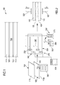
Figure 1 shows a section view of the safety mirror object of the present invention; -
Figure 2 shows a synthetic diagram of the production process of the safety mirror object of the present invention; -
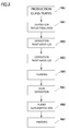
Figure 3 shows a flow char of the production process of the safety mirror object of the present invention. - With reference to the annexed figures, with the
reference number 100 is indicated in its complex a safety mirror. - The safety mirror has been conceived for allowing that also in case of shock there are not dangerous fractures of the glass plates of which it is composed; in detail, this means that when broken, the
safety mirror 100 object of the present invention breaks but the single parts of glass rest anyway jointed for a maximal part to the resting part of the structure, and do not unglue from this last. - As it is shown in detail in
figure 1 , on thesafety mirror 100 object of the present invention there are a first and a second plate ofglass material 110, each one having a first and a second side; the first side of each of the two plates is directed outwards thesafety mirror 100, while the second side, opposed respective to the first, is directed inwards thesafety mirror 100. - The second side is painted, and therefore has a painted
layer 120 superimposed to the glassy layer and of a significantly smaller thickness. - The painted
layer 120 represents a layer which is necessary for protecting the thin layer of silver or aluminum, preferably but in a non-limiting extent is deposited on a side of the plate of glass material by means of electrolysis, that realizes a reflective layer. - If needed on the layer of silver or aluminum a copper layer protection is deposited.
- Interposed between the two plates of
glass material 110 there is alayer 130 of plastic buffer material, a material capable of absorbing the shocks deforming significantly more than the glass, and wherein said material has features of plastic deformability and return to the original shape following of an impact. The plastic material layer, that as it will be further described in the following part of the description is realized starting from a fluid glue, represents a layer of mixing of two layers of fluid glue that were deposited in advance on the plates ofglass material 110. - It is therefore realized a
safety mirror 100 composed by a sandwich that, once observed in section an proceeding axially from one side to the other has, in order: a first plate ofglass material 110, a paintedlayer 120 superimposed to the second side of the first plate ofglass material 110, the layer ofbuffer plastic material 130, a second paintedlayer 120 superimposed to the second side of the second plate ofglass material 110, and the second plate of glass material. Preferably, but in a non-limiting extent, said paintedlayer 120 is fixed to the underlying layer in an infrared oven, that preferably but in a non-limiting extent is brought to a temperature comprised between 100°C and 200°C The safety mirror realized by means of the present invention is characterized in that it is realized through a peculiar production process suitable of increasing the robustness and security thereof in case of impact of any object against the surface. - With reference to
figure 3 , the process of production of thesafety mirror 100 object of the present invention is conveniently realized by two or more production machines for producing said safety mirror. - The process of production of the mirror starts from the production of two glassy laminates that will be cut for producing said two plates of glass material 110 (block 1000). The cutting and grinding process of the plates takes place according to known techniques.
- A first phase of working comprises therefore the painting of one of the two faces of each of the two plates of
glass material 110, so that to realize said painted layer 120 (block 1002) that protects the layer of reflecting material previously applied (block 1001) to the plate ofglass material 110. - Subsequently, in a second and subsequent phase of working, both the plates of
glass material 110, in a first station of the machine for producing said safety mirror, are preheated (block 1003) by means of for example and in a non-limiting extent anelectric heater 200 that heats the plates of glass material withradiation 210. - The two plates of
glass material 110 come therefore in a second station of the machine for producing saidsafety mirror 110, being made to slide on a conveying belt or on an equivalent motion means. - In said
second station 220, there is a plurality ofgas supplying nozzles 240, arranged in proximity of each of the two plates of glass material. -
Said nozzle 240 are fed by means or respective conduits from a gas source, for example atank 230, preferably containing propane or methane. - The two plates of
glass material 110 are therefore subsequently flamed (block 1004) with naked flame, fed specifically by saidnozzles 240, from the side where there is the painted layer 120.The applicant has observed that using a blue flame, therefore a flame with high tax of combusted oxygen and therefore an oxidizing flame, releases OH-radicals suitable of enhancing the features of uniform heating of the mirror surface, and as well of advantageously activating the sites wherein the glue can "grip" to another surface, so that the subsequent step of deposition of the glue - as it will be better described hereinafter - is more efficient and concurs with increasing the overall resistance of the safety mirror. The applicant underlines that said process of activation of the sites wherein the glue can grip, directly derives from a combination of heating and chemical combination of the flame with the glue itself. - On each plate of
glass material 110, by means of a couple ofheated deposition rollers 250, a layer of fluid glue is deposed by means of supplying nozzles 260 (block 1005). The presence ofheated deposition rollers 250 allows for using a glue that at ambient temperature is significantly more viscous (or either semi-solid), while instead the absence of heated deposition rollers would necessarily cause the use of a glue being too fluid for a correct application. Said proceeding is therefore the preferable one, since it has the best distribution and adhesion of the fluid glue on both the plates ofglass material 110. Anyway, the applicant observes that the layer of fluid glue could also be deposited on a single plate ofglass material 110, in a double amount [g/m2], even if not obtaining the same equal superficial adhesion on both the plates, since the glue that would be deposited on the second plate of glass material at a time forcedly subsequent respective to that wherein it is distended on the first plate ofglass material 110, with the riks of partial polymerization of the glue, partially soluble with a slight increase of the temperature of deposition and with a speed-up of the coupling process of the plates described in the present invention. The applicant has observed that the glue that better guarantees the adhesion and, when solidified, realizes a layer ofplastic buffer material 130 capable of conferring the best features of robustness to the safety mirror, is a glue, that in a preferred and non-limiting production embodiment is a glue characterized by a viscosity comprised in the interval [1000-2000] Pa*s and more preferably1250 Pa*s (a 140 °C).The applicant has observed that for the aforementioned features, the glue which is preferable is therefore a hot-melt glue (so called hot melt), of a thermoplastic elastomeric (TPE) type, and more precisely a glue selected between the glues listed in the herewith following list: - ethylene vinyl acetate (EVA);
- polyethylene (PE);
- styrene-butadiene co-polymer (SBS);
- thermoplastic polyurethane (TPU);
- amorphous poly-olefin (APAO);
- co-polyamide (CoPA);
- co-polyester (CoPES);
- reactive hot melt (RHM);
- In association to the glue with the aforementioned features, the applicant has observed that the best final robustness of the mirror is obtained in case the plates of
glass material 110 before the deposition of the glue, are at a temperature around 100°C and anyway not beyond the interval [50-150]°C. The applicant has furthermore illustrated that keeping the temperature in the optimal neighborhood of 100°C - temperature that represents the optimal compromise between the correct heating and optimization of the subsequent glue distribution with its fusion - allows for reducing the overall heating of the material respective to the known art, obtaining an economically more convenient process. - In detail, so that the glue presents the correct features of adhesion and keeping of plasticity in time, it must be treated according to the following process.
- In detail, the polyester based glue, is collected from waterproof or
hermetic containers 290, possibly but non forcedly in vacuum condition, having a plurality ofpellets 300, that are transferred and kept in a controlled atmosphere within thetank 270 being for example heated through anelectric serpentine 280. - In detail, said controlled atmosphere is obtained by de-humidifier filters arranged in a closed environment that surrounds the
tank 270 and thepellets containers 290. The applicant has in fact observed that the presence of an excess of humidity in the atmosphere, also starting frompellets 300, starts a chemical reaction an activates a partial polymerization of the glue too early, and this causes a reduction of the adhesive and plasticity featurs of the layer of glue that influence negatively the final production of the safety mirror in terms of resistance to the impact and in the shear test. - In detail, the tank is heated in such a way to keep the temperature of the glue therein contained in the interval comprised between 100°C and 200°C; the glue is therefore collected and sent towarsd the supplying nozzels for then being deposited on the plates of
glass material 110, and in detail on the painted sides with paintedlayer 120. - The applicant has observed that the amount of glue distributed on said faces shall be carefully set, since an excess of glue - as well as an insufficient amount - determinates a reduction of the features of robustness of the mirror. An excess of glue is furthermore a source of waste.
- Therefore the applicant has observed that the peak of final robustness of the
safety mirror 100 object of the present invention is obtained in case on the painted sides of each of the two plates ofglass material 110 are deposited between 100g/m2 and 200g/m2 of fluid glue. Therefore a peculiar feature of the process herewith described is to have a layer of gluing material for each one layer ofglass material 110, that are then superimposed so that from two layers of gluing material, results a single one. The applicant underlines that said amount of glue deposited shall be intended as being purely exemplificative and non-limiting, since it represents the optimal amount of glue to be deposited for surface unit, but referred to the specific type of glue treated. - In case in a sub-optimal but anyway innovative way the process is realized with the deposition on a single plate of glass material, the amount of glue to be deposited results be the double. Therefore, where it is present on the painted side only one deposited layer, the density is comprised in the interval between 200g/m2 and 400g/m2. Therefore, into the
second station 220, the speed of sliding of thedeposition rollers 250 and the amount of fluid glue fed by the supplyingnozzles 260 is such as it is anyway deposited an overall layer of glue in a measure comprised between 100g/m2 and 200g/m2 of fluid glue. Said amount of deposited glue per unit of surface shall not be intended as limiting, since many types of glue can be used as already yet described. The presence of deposition rollers, anyway allows for having a layer of glue on each of the two plates of glass, realized in such a way to not to have bubbles therein enclosed - bubbles that could reduce the overall adhesion of the layer and therefore the robustness of thesafety mirror 100, and as well have the exposed side of said layer as uniform as possible. - In a preferred production embodiment, the two plates of
glass material 110 are simultaneously treated both in terms of flaming, both in terms of deposition of layer of fluid glue. The applicant has observed that this represents the most optimal solution for reaching the uniformity of behavior of each of the two sub-ensembles ofglass material 110 plates - layer of glue. - Subsequently, the two sub-ensembles plate of glass material 110 - layer of glue, are coupled together so as to form the sandwich described at the beginning of the present description (block 1006).
- Preferably, said coupling takes place by means of a step of superimposition and pressing of the two sub-ensembles that is performed in a third station of the machine for producing the safety mirror.
- In detail, the two sub-ensembles plate of glass material 110 - layer of glue are superimposed in such a way to result planarly parallel and oriented in such a way that the two layers of glue are faced one towards the other, so that they can bond each other ans uniformly mix to the end of realizing the layer of
plastic buffer material 130. - In a preferred and non-limiting production embodiment of the present invention, between the deposition of the fluid glue on the painted
layer 120 and the coupling of the two sub-ensembles to the end of pressing, no more than 60s can lapse. Also in case types of glue different than the one previously described are used, the coupling after 60 seconds - and more preferably within 30 seconds - risks to see the two layers of glue yet too much polymerized in surface, and the final adhesion of each other - since these two layers join specifically due to the superimposition of the plates - risks of be less robust and this could cause that, in case of impact of the mirror with an object, different fragments of plates of glass material are dispersed in the environment no more being reciprocally joint one another. - True as wells is that between the deposition of the fluid glue on the painted
layer 120 and the coupling of the two sub-ensembles to the end of pressing, not less than 5s should lapse, this for guarantying that the chemical reaction of the fluid glue with the air can correctly start. - In detail, said pressing (block 1007) takes place by means of a couple of
pressing means 320, that act on the side of each of the plates ofglass material 110 that is opposed respective to the side has the paintedlayer 120, acting with a force F perpendicular to the plane detected by the plates of glass material. - Finally, at least one of the two plates of glass material can comprise metal inclusions suitable for providing transparency and/or color of the same different than the total transparency and neutrality of color typical of the white mirrors. On the
safety mirror 100 object of the present invention some tests have been made. In detail, between the various tests performed on the mirror object of the present invention, it has been performed a test of breaking by letting a ball of metal of 1 kilogram fall on a sample of thesafety mirror 100 from an height of 2,5m. The ball has been left fall freely, without initial acceleration on a sample formed by two plates of glass material each being 3mm thick. - Following the impact, the
safety mirror 100 object of the present invention has been fractured, in detail, on the plate of glass opposed respective to that onto which the ball impacted. Even though fractured, the plate opposed respective to that onto which the ball ha impacted did not disperse fragments of glass, that rested stuck with the other and/or anayway still at least partially glued to the intermediate plastic buffer layer. From the previous test is therefore possible to attribute an impact resistance significantly higher respective to that it could be obtained by a traditional process in detail using very liquid glues deposited with cold rollers. - This means that the
safety mirror 100 object of the present invention, realized through the method up to here described, has a peculiar property not olny of impeding the dispersion of fragments, but also of fracturing on the opposite side respective to that it it hit. This vantage allows a significantly higher safety, in particular in those applications in bathroom or similar. In said applications, and in case of a shock of an entity such as to cause the fracture, thesafety mirror 100 object of the present invention cracks anyway facing either to the wall or inwards respective to the bathroom cabinet. Therefore, neither the lines of fracture can risk to directly wound the user that clumsily impacts thereto, since the fractures and cracks lay on the opposite side, not directly accessible to the user itself. Also in case the fracture of the opposite plate releases fragments of glass, it is clear that said fragments would rest anyway dispersed on the opposite side respective to the side onto which the user impacts, further reducing the risk of wounding also respective to the conventional type safety mirrors. - Furthermore, on the
safety mirror 100 object of the present invention has been also performed a bar reciprocal sliding test. On a reciprocal area of gluing of two plates of glass material equivalent to 24 x 12.5 mm, the force obtained for causing a division thereof is equal or higher than0.4 MPa. Advantageously, therefore, the mirror object of the present invention, realized by means of the previously described process, is very robust not only in terms of impact but also is optimized in reducing the risk of separation of the two plates of glass material two to a reciprocal sliding. - It is finally clear that to the object of the present invention additions, adaptations or variants can be brought, provided they are obvious for the skilled person, without for this departing from the scope of protection provided by the annexed claims.
Claims (17)
- Safety mirror (100), characterized in that it comprises a sandwich (110, 120, 130) in turn comprising a couple of plates of glass material (110) planarly parallel and separated each other by a layer of plastic buffer material (130) realizing a breakage-preventing layer of said safety mirror (100); each plate of glass material (110) of the said couple of plates of glass material has a painted side (120) that faces towards said layer of plastic buffer material (130); and wherein said a painted side (120) and wherein said layer of plastic buffer material (130) is a layer of mixing for compression of a couple of layers of gluing material in advance arranged on at least one of the painted sides (120).
- Safety mirror (100) according to claim 1, characterized in that said layer of plastic buffer material (130) comprises at least one layer of hot-melt glue (so called hot melt), of a thermoplastic elastomeric (TPE) type, and wherein said hot-melt glue (so called hot melt), of a thermoplastic elastomeric (TPE) type has to a temperature of 140°C a viscosity comprised in the interval 1000-2000 Pa*s.
- Safety mirror (100) according to claim 1, characterized in that said layer of glue is realized starting from a couple of layers of gluing material, and wherein said couple of layers of gluing material has per each layer a density comprised in the interval between 100g/m2 and 200g/m2.
- Safety mirror (100) according to claim 1, characterized in that said single layer of glue has a density comprised in the interval between 200g/m2 and 400g/m2.
- Safety mirror (100) according to any of the preceding claims, characterized in that it has a lap-shear resistance, on an area of gluing equal to 24 x 12.5 mm, higher than 0,4MPa.
- Safety mirror (100) according to any of the preceding claims, characterized in that between said painted layer (120) and said plate of glass material (110) is interposed a layer of reflecting material realized in silver or in aluminum.
- Safety mirror (100) according to claim 3, wherein each layer of gluing material is superimposed to a respective painted side (120).
- Method of production of a safety mirror (100), said method comprising:- a preventive step of production of a couple of plates (110) of glass material, of which at least one plate of the said couple of plates of glass material (110) has a painted side (120);- a second step of application of a layer of gluing material on said painted side (120) of at least one plate of the said couple of plates of glass material (110);- a further step of superimposition of the said painted sides (120) with said layer gluing material, realizing a sandwich (110, 120, 130) formed by a couple of plates of glass material (110) planarly parallel and separated by a layer of plastic buffer material (130) deriving from the union of said at least a layer of gluing material positioned beforehand on said painted side; and- a step of pressing of said sandwich (110, 120, 130) in a direction orthogonal to the direction defined by said planes of the plates of glass material (110);
said method comprising furthermore a step of pre-heating of each of the plates of glass material (110) being part of the said couple of plates. - Method according to claim 8, characterized in that it comprises a step of heating of a painted side (120) of each of the said plates by means of a naked flame (240), wherein said naked flame is a blue flame containing OH radicals deriving from the combustion of gases at least partially comprising methane or propane.
- Method according to any of the claims 8, 9, characterized in that said plastic buffer material is realized starting from a fluid glue, and wherein said method comprises a step of deposition by means of deposition rollers (250) of said fluid glue on said painted side (120) of each of the plates of the said couple of plates of glass material (110), before said step of superimposition of the said painted sides (120).
- Method according to any of the preceding claims 8-10, characterized in that said plastic buffer material (130) derives from a fluid glue and said method comprises a step of extraction from waterproof containers (290) of a plurality of pellets (300) of said glue, starting from a waterproof container, and a step of deposition of a fused portion of said pellets (300) of said glue on said painted side (120) by means of a step of de-humidification of the air with which said glue comes into contact before the deposition on the side of each of the said plates of glass material (110).
- Method according to any of the preceding claims 8-11, characterized in that said step of pre-heating comprises bringing said plates of glass material (110) to a temperature comprised in the interval between [50-150] °C, preferably 100°C.
- Method according to claim 10, characterized in that said step of step of deposition by means of deposition rollers (250) of said fluid glue comprises a step of preventive heating of the said glue to a temperature comprised between [150-160]°C and a step of heating of said deposition roller up to 150°C.
- Method according to claim 13, characterized in that it comprises a step of deposition of said fluid glue for an amount comprised between 100g/m2 and 200g/m2 on each of the said painted sides (120).
- Method according to claim 8, characterized in that said step of superimposition of the said painted sides (120) with said layer of gluing material takes place after an interval of time between 5s and 60s after said step of deposition of the said fluid glue.
- Method according to any of the preceding claims 8-14, characterized in that said glue is a hot-melt glue (so called hot melt), of a thermoplastic elastomeric (TPE) type.
- Method according to claim 15, characterized in that said glue comprises at least one among:- ethylene vinyl acetate (EVA);- polyethylene (PE);- styrene-butadiene co-polymer (SBS);- thermoplastic polyurethane (TPU);- amorphous poly-alpha olefins (APAO);- co-polyamide (CoPA);- co-polyester (CoPES);- reactive hot melt (RHM).
Priority Applications (1)
| Application Number | Priority Date | Filing Date | Title |
|---|---|---|---|
| PL16171366T PL3135482T3 (en) | 2015-08-24 | 2016-05-25 | Double safety mirror and method of manufacturing thereof |
Applications Claiming Priority (2)
| Application Number | Priority Date | Filing Date | Title |
|---|---|---|---|
| ITUB2015A003198A ITUB20153198A1 (en) | 2015-08-24 | 2015-08-24 | DOUBLE SAFETY MIRROR AND METHOD OF REALIZING THE SAME. |
| CH01214/15A CH711444B1 (en) | 2015-08-24 | 2015-08-24 | Double safety mirror and method of making it. |
Publications (2)
| Publication Number | Publication Date |
|---|---|
| EP3135482A1 true EP3135482A1 (en) | 2017-03-01 |
| EP3135482B1 EP3135482B1 (en) | 2020-11-18 |
Family
ID=56026778
Family Applications (1)
| Application Number | Title | Priority Date | Filing Date |
|---|---|---|---|
| EP16171366.4A Active EP3135482B1 (en) | 2015-08-24 | 2016-05-25 | Double safety mirror and method of manufacturing thereof |
Country Status (4)
| Country | Link |
|---|---|
| EP (1) | EP3135482B1 (en) |
| DK (1) | DK3135482T3 (en) |
| ES (1) | ES2843259T3 (en) |
| PL (1) | PL3135482T3 (en) |
Citations (8)
| Publication number | Priority date | Publication date | Assignee | Title |
|---|---|---|---|---|
| US1885232A (en) * | 1930-10-20 | 1932-11-01 | Duplate Corp | Mirror |
| US1934802A (en) * | 1930-02-11 | 1933-11-14 | Pittsburgh Plate Glass Co | Moving picture screen and method of making it |
| US2062646A (en) * | 1936-02-07 | 1936-12-01 | Joseph H Fox | Method of framing double face pocketbook mirrors |
| US2468568A (en) * | 1945-09-27 | 1949-04-26 | Safetee Glass Company | Laminated mirror |
| GB2097328A (en) * | 1981-04-24 | 1982-11-03 | Glaverbel | Laminated reflective panels |
| US5246764A (en) | 1991-10-21 | 1993-09-21 | Monsanto Company | Laminated glazing with improved impact strength |
| EP0882997A1 (en) * | 1997-06-06 | 1998-12-09 | Globe-Amerada Glass Company | Laminated safety mirror with reflective coating adjacent the bonding layer |
| US20070223096A1 (en) * | 2006-03-23 | 2007-09-27 | Guardian Industries Corp., & Centre Luxembourgeois De Recherches Pour Le Verre Et Al Caramique S.A. | Parabolic trough or dish reflector for use in concentrating solar power apparatus and method of making same |
-
2016
- 2016-05-25 EP EP16171366.4A patent/EP3135482B1/en active Active
- 2016-05-25 PL PL16171366T patent/PL3135482T3/en unknown
- 2016-05-25 DK DK16171366.4T patent/DK3135482T3/en active
- 2016-05-25 ES ES16171366T patent/ES2843259T3/en active Active
Patent Citations (8)
| Publication number | Priority date | Publication date | Assignee | Title |
|---|---|---|---|---|
| US1934802A (en) * | 1930-02-11 | 1933-11-14 | Pittsburgh Plate Glass Co | Moving picture screen and method of making it |
| US1885232A (en) * | 1930-10-20 | 1932-11-01 | Duplate Corp | Mirror |
| US2062646A (en) * | 1936-02-07 | 1936-12-01 | Joseph H Fox | Method of framing double face pocketbook mirrors |
| US2468568A (en) * | 1945-09-27 | 1949-04-26 | Safetee Glass Company | Laminated mirror |
| GB2097328A (en) * | 1981-04-24 | 1982-11-03 | Glaverbel | Laminated reflective panels |
| US5246764A (en) | 1991-10-21 | 1993-09-21 | Monsanto Company | Laminated glazing with improved impact strength |
| EP0882997A1 (en) * | 1997-06-06 | 1998-12-09 | Globe-Amerada Glass Company | Laminated safety mirror with reflective coating adjacent the bonding layer |
| US20070223096A1 (en) * | 2006-03-23 | 2007-09-27 | Guardian Industries Corp., & Centre Luxembourgeois De Recherches Pour Le Verre Et Al Caramique S.A. | Parabolic trough or dish reflector for use in concentrating solar power apparatus and method of making same |
Also Published As
| Publication number | Publication date |
|---|---|
| PL3135482T3 (en) | 2021-06-14 |
| ES2843259T3 (en) | 2021-07-16 |
| EP3135482B1 (en) | 2020-11-18 |
| DK3135482T3 (en) | 2021-01-18 |
Similar Documents
| Publication | Publication Date | Title |
|---|---|---|
| AU2002360716B2 (en) | Glass lamination process and apparatus | |
| CN1271646A (en) | Method and apparatus for cutting laminated products made of hard brittle material and plastics | |
| RU2014118977A (en) | LAMINATE PANEL WITHOUT OPPONENT PAPER | |
| RU2720685C1 (en) | Method of producing curved multilayer window glass containing thin glass sheet | |
| UA127075C2 (en) | METHOD OF MANUFACTURING THERMOPLASTIC WEAR-RESISTANT FILM, BUILDING PANEL AND METHOD OF ITS PRODUCTION | |
| JP7051036B2 (en) | Manufacturing method of bonded glass including double-sided mirror | |
| CA2534385A1 (en) | Process for the surface finishing of materials via application in particular of transparent layers based on polymethacrylates | |
| US20160108661A1 (en) | Fire protection glazing and method for producing a fire protection glazing | |
| CN101367287A (en) | Manufacturing method of multilayer composite board of polyurethane | |
| IL197126A (en) | Methods for making multiple layer glazing panels | |
| KR20070106718A (en) | Self-adhesive laminate | |
| EP3135482B1 (en) | Double safety mirror and method of manufacturing thereof | |
| CN108215431A (en) | A kind of production method of double toughened interlayer glass | |
| GB970931A (en) | Improvements relating to the manufacture of laminates | |
| EP1814726A1 (en) | Method and apparatus for laminating glass panels | |
| KR20180121672A (en) | Glass manufacturing methods and apparatus | |
| AU645086B2 (en) | Method of laminating glass | |
| NO955174L (en) | Method of applying markings or marking to a substrate | |
| CN104635283A (en) | Composite bright enhancement film and production method thereof | |
| US20120227901A1 (en) | Method of lamination using radio frequency heating and pressure | |
| CH711444B1 (en) | Double safety mirror and method of making it. | |
| CN104311158B (en) | A kind of dumb light underglaze colour throws the production method of glazed brick | |
| EP1702749B1 (en) | Method, and consequent product, for the creation of decorative glass plates that are resistent to knocks and thermal shocks | |
| RU2016141976A (en) | METHOD FOR FINISHING A PLATE BASED ON WOOD MATERIALS | |
| CA2303778C (en) | Glass bending process |
Legal Events
| Date | Code | Title | Description |
|---|---|---|---|
| PUAI | Public reference made under article 153(3) epc to a published international application that has entered the european phase |
Free format text: ORIGINAL CODE: 0009012 |
|
| STAA | Information on the status of an ep patent application or granted ep patent |
Free format text: STATUS: THE APPLICATION HAS BEEN PUBLISHED |
|
| STAA | Information on the status of an ep patent application or granted ep patent |
Free format text: STATUS: REQUEST FOR EXAMINATION WAS MADE |
|
| AK | Designated contracting states |
Kind code of ref document: A1 Designated state(s): AL AT BE BG CH CY CZ DE DK EE ES FI FR GB GR HR HU IE IS IT LI LT LU LV MC MK MT NL NO PL PT RO RS SE SI SK SM TR |
|
| AX | Request for extension of the european patent |
Extension state: BA ME |
|
| 17P | Request for examination filed |
Effective date: 20170215 |
|
| RBV | Designated contracting states (corrected) |
Designated state(s): AL AT BE BG CH CY CZ DE DK EE ES FI FR GB GR HR HU IE IS IT LI LT LU LV MC MK MT NL NO PL PT RO RS SE SI SK SM TR |
|
| STAA | Information on the status of an ep patent application or granted ep patent |
Free format text: STATUS: EXAMINATION IS IN PROGRESS |
|
| 17Q | First examination report despatched |
Effective date: 20180315 |
|
| GRAP | Despatch of communication of intention to grant a patent |
Free format text: ORIGINAL CODE: EPIDOSNIGR1 |
|
| STAA | Information on the status of an ep patent application or granted ep patent |
Free format text: STATUS: GRANT OF PATENT IS INTENDED |
|
| RIC1 | Information provided on ipc code assigned before grant |
Ipc: A45D 42/00 20060101ALN20200608BHEP Ipc: B32B 17/10 20060101AFI20200608BHEP |
|
| RIC1 | Information provided on ipc code assigned before grant |
Ipc: B32B 17/10 20060101AFI20200617BHEP Ipc: A45D 42/00 20060101ALN20200617BHEP |
|
| INTG | Intention to grant announced |
Effective date: 20200630 |
|
| GRAS | Grant fee paid |
Free format text: ORIGINAL CODE: EPIDOSNIGR3 |
|
| GRAA | (expected) grant |
Free format text: ORIGINAL CODE: 0009210 |
|
| STAA | Information on the status of an ep patent application or granted ep patent |
Free format text: STATUS: THE PATENT HAS BEEN GRANTED |
|
| AK | Designated contracting states |
Kind code of ref document: B1 Designated state(s): AL AT BE BG CH CY CZ DE DK EE ES FI FR GB GR HR HU IE IS IT LI LT LU LV MC MK MT NL NO PL PT RO RS SE SI SK SM TR |
|
| REG | Reference to a national code |
Ref country code: GB Ref legal event code: FG4D |
|
| REG | Reference to a national code |
Ref country code: CH Ref legal event code: EP |
|
| REG | Reference to a national code |
Ref country code: IE Ref legal event code: FG4D |
|
| REG | Reference to a national code |
Ref country code: DE Ref legal event code: R096 Ref document number: 602016047955 Country of ref document: DE |
|
| REG | Reference to a national code |
Ref country code: AT Ref legal event code: REF Ref document number: 1335294 Country of ref document: AT Kind code of ref document: T Effective date: 20201215 |
|
| REG | Reference to a national code |
Ref country code: FI Ref legal event code: FGE |
|
| REG | Reference to a national code |
Ref country code: DK Ref legal event code: T3 Effective date: 20210115 |
|
| REG | Reference to a national code |
Ref country code: NO Ref legal event code: T2 Effective date: 20201118 |
|
| REG | Reference to a national code |
Ref country code: CH Ref legal event code: NV Representative=s name: FIAMMENGHI-FIAMMENGHI, CH |
|
| REG | Reference to a national code |
Ref country code: SE Ref legal event code: TRGR |
|
| REG | Reference to a national code |
Ref country code: NL Ref legal event code: FP |
|
| PG25 | Lapsed in a contracting state [announced via postgrant information from national office to epo] |
Ref country code: PT Free format text: LAPSE BECAUSE OF FAILURE TO SUBMIT A TRANSLATION OF THE DESCRIPTION OR TO PAY THE FEE WITHIN THE PRESCRIBED TIME-LIMIT Effective date: 20210318 Ref country code: RS Free format text: LAPSE BECAUSE OF FAILURE TO SUBMIT A TRANSLATION OF THE DESCRIPTION OR TO PAY THE FEE WITHIN THE PRESCRIBED TIME-LIMIT Effective date: 20201118 Ref country code: GR Free format text: LAPSE BECAUSE OF FAILURE TO SUBMIT A TRANSLATION OF THE DESCRIPTION OR TO PAY THE FEE WITHIN THE PRESCRIBED TIME-LIMIT Effective date: 20210219 |
|
| PG25 | Lapsed in a contracting state [announced via postgrant information from national office to epo] |
Ref country code: BG Free format text: LAPSE BECAUSE OF FAILURE TO SUBMIT A TRANSLATION OF THE DESCRIPTION OR TO PAY THE FEE WITHIN THE PRESCRIBED TIME-LIMIT Effective date: 20210218 Ref country code: IS Free format text: LAPSE BECAUSE OF FAILURE TO SUBMIT A TRANSLATION OF THE DESCRIPTION OR TO PAY THE FEE WITHIN THE PRESCRIBED TIME-LIMIT Effective date: 20210318 Ref country code: LV Free format text: LAPSE BECAUSE OF FAILURE TO SUBMIT A TRANSLATION OF THE DESCRIPTION OR TO PAY THE FEE WITHIN THE PRESCRIBED TIME-LIMIT Effective date: 20201118 |
|
| REG | Reference to a national code |
Ref country code: LT Ref legal event code: MG9D |
|
| PG25 | Lapsed in a contracting state [announced via postgrant information from national office to epo] |
Ref country code: HR Free format text: LAPSE BECAUSE OF FAILURE TO SUBMIT A TRANSLATION OF THE DESCRIPTION OR TO PAY THE FEE WITHIN THE PRESCRIBED TIME-LIMIT Effective date: 20201118 |
|
| REG | Reference to a national code |
Ref country code: ES Ref legal event code: FG2A Ref document number: 2843259 Country of ref document: ES Kind code of ref document: T3 Effective date: 20210716 |
|
| PG25 | Lapsed in a contracting state [announced via postgrant information from national office to epo] |
Ref country code: SM Free format text: LAPSE BECAUSE OF FAILURE TO SUBMIT A TRANSLATION OF THE DESCRIPTION OR TO PAY THE FEE WITHIN THE PRESCRIBED TIME-LIMIT Effective date: 20201118 Ref country code: RO Free format text: LAPSE BECAUSE OF FAILURE TO SUBMIT A TRANSLATION OF THE DESCRIPTION OR TO PAY THE FEE WITHIN THE PRESCRIBED TIME-LIMIT Effective date: 20201118 Ref country code: SK Free format text: LAPSE BECAUSE OF FAILURE TO SUBMIT A TRANSLATION OF THE DESCRIPTION OR TO PAY THE FEE WITHIN THE PRESCRIBED TIME-LIMIT Effective date: 20201118 Ref country code: EE Free format text: LAPSE BECAUSE OF FAILURE TO SUBMIT A TRANSLATION OF THE DESCRIPTION OR TO PAY THE FEE WITHIN THE PRESCRIBED TIME-LIMIT Effective date: 20201118 Ref country code: LT Free format text: LAPSE BECAUSE OF FAILURE TO SUBMIT A TRANSLATION OF THE DESCRIPTION OR TO PAY THE FEE WITHIN THE PRESCRIBED TIME-LIMIT Effective date: 20201118 |
|
| REG | Reference to a national code |
Ref country code: DE Ref legal event code: R097 Ref document number: 602016047955 Country of ref document: DE |
|
| PLBE | No opposition filed within time limit |
Free format text: ORIGINAL CODE: 0009261 |
|
| STAA | Information on the status of an ep patent application or granted ep patent |
Free format text: STATUS: NO OPPOSITION FILED WITHIN TIME LIMIT |
|
| 26N | No opposition filed |
Effective date: 20210819 |
|
| PG25 | Lapsed in a contracting state [announced via postgrant information from national office to epo] |
Ref country code: AL Free format text: LAPSE BECAUSE OF FAILURE TO SUBMIT A TRANSLATION OF THE DESCRIPTION OR TO PAY THE FEE WITHIN THE PRESCRIBED TIME-LIMIT Effective date: 20201118 Ref country code: IT Free format text: LAPSE BECAUSE OF FAILURE TO SUBMIT A TRANSLATION OF THE DESCRIPTION OR TO PAY THE FEE WITHIN THE PRESCRIBED TIME-LIMIT Effective date: 20201118 |
|
| PG25 | Lapsed in a contracting state [announced via postgrant information from national office to epo] |
Ref country code: SI Free format text: LAPSE BECAUSE OF FAILURE TO SUBMIT A TRANSLATION OF THE DESCRIPTION OR TO PAY THE FEE WITHIN THE PRESCRIBED TIME-LIMIT Effective date: 20201118 |
|
| PG25 | Lapsed in a contracting state [announced via postgrant information from national office to epo] |
Ref country code: MC Free format text: LAPSE BECAUSE OF FAILURE TO SUBMIT A TRANSLATION OF THE DESCRIPTION OR TO PAY THE FEE WITHIN THE PRESCRIBED TIME-LIMIT Effective date: 20201118 Ref country code: LU Free format text: LAPSE BECAUSE OF NON-PAYMENT OF DUE FEES Effective date: 20210525 |
|
| PG25 | Lapsed in a contracting state [announced via postgrant information from national office to epo] |
Ref country code: IE Free format text: LAPSE BECAUSE OF NON-PAYMENT OF DUE FEES Effective date: 20210525 |
|
| PG25 | Lapsed in a contracting state [announced via postgrant information from national office to epo] |
Ref country code: IS Free format text: LAPSE BECAUSE OF FAILURE TO SUBMIT A TRANSLATION OF THE DESCRIPTION OR TO PAY THE FEE WITHIN THE PRESCRIBED TIME-LIMIT Effective date: 20210318 |
|
| PG25 | Lapsed in a contracting state [announced via postgrant information from national office to epo] |
Ref country code: HU Free format text: LAPSE BECAUSE OF FAILURE TO SUBMIT A TRANSLATION OF THE DESCRIPTION OR TO PAY THE FEE WITHIN THE PRESCRIBED TIME-LIMIT; INVALID AB INITIO Effective date: 20160525 |
|
| REG | Reference to a national code |
Ref country code: AT Ref legal event code: UEP Ref document number: 1335294 Country of ref document: AT Kind code of ref document: T Effective date: 20201118 |
|
| PG25 | Lapsed in a contracting state [announced via postgrant information from national office to epo] |
Ref country code: CY Free format text: LAPSE BECAUSE OF FAILURE TO SUBMIT A TRANSLATION OF THE DESCRIPTION OR TO PAY THE FEE WITHIN THE PRESCRIBED TIME-LIMIT Effective date: 20201118 |
|
| PG25 | Lapsed in a contracting state [announced via postgrant information from national office to epo] |
Ref country code: MK Free format text: LAPSE BECAUSE OF FAILURE TO SUBMIT A TRANSLATION OF THE DESCRIPTION OR TO PAY THE FEE WITHIN THE PRESCRIBED TIME-LIMIT Effective date: 20201118 |
|
| PG25 | Lapsed in a contracting state [announced via postgrant information from national office to epo] |
Ref country code: MT Free format text: LAPSE BECAUSE OF FAILURE TO SUBMIT A TRANSLATION OF THE DESCRIPTION OR TO PAY THE FEE WITHIN THE PRESCRIBED TIME-LIMIT Effective date: 20201118 |
|
| REG | Reference to a national code |
Ref country code: CH Ref legal event code: U11 Free format text: ST27 STATUS EVENT CODE: U-0-0-U10-U11 (AS PROVIDED BY THE NATIONAL OFFICE) Effective date: 20260601 |
|
| PGFP | Annual fee paid to national office [announced via postgrant information from national office to epo] |
Ref country code: NL Payment date: 20260526 Year of fee payment: 11 |
|
| PGFP | Annual fee paid to national office [announced via postgrant information from national office to epo] |
Ref country code: ES Payment date: 20260601 Year of fee payment: 11 |
|
| PGFP | Annual fee paid to national office [announced via postgrant information from national office to epo] |
Ref country code: GB Payment date: 20260527 Year of fee payment: 11 Ref country code: DK Payment date: 20260525 Year of fee payment: 11 Ref country code: PL Payment date: 20260506 Year of fee payment: 11 |
|
| PGFP | Annual fee paid to national office [announced via postgrant information from national office to epo] |
Ref country code: DE Payment date: 20260528 Year of fee payment: 11 |
|
| PGFP | Annual fee paid to national office [announced via postgrant information from national office to epo] |
Ref country code: NO Payment date: 20260528 Year of fee payment: 11 |
|
| PGFP | Annual fee paid to national office [announced via postgrant information from national office to epo] |
Ref country code: FI Payment date: 20260525 Year of fee payment: 11 Ref country code: AT Payment date: 20260528 Year of fee payment: 11 Ref country code: SE Payment date: 20260527 Year of fee payment: 11 |
|
| PGFP | Annual fee paid to national office [announced via postgrant information from national office to epo] |
Ref country code: CH Payment date: 20260601 Year of fee payment: 11 Ref country code: BE Payment date: 20260527 Year of fee payment: 11 |
|
| PGFP | Annual fee paid to national office [announced via postgrant information from national office to epo] |
Ref country code: CZ Payment date: 20260512 Year of fee payment: 11 Ref country code: TR Payment date: 20260511 Year of fee payment: 11 |
|
| PGFP | Annual fee paid to national office [announced via postgrant information from national office to epo] |
Ref country code: FR Payment date: 20260525 Year of fee payment: 11 |