EP3135452B1 - Method of producing a colored plastic article - Google Patents
Method of producing a colored plastic article Download PDFInfo
- Publication number
- EP3135452B1 EP3135452B1 EP16189824.2A EP16189824A EP3135452B1 EP 3135452 B1 EP3135452 B1 EP 3135452B1 EP 16189824 A EP16189824 A EP 16189824A EP 3135452 B1 EP3135452 B1 EP 3135452B1
- Authority
- EP
- European Patent Office
- Prior art keywords
- container
- integrated pump
- motor
- pump cap
- liquid
- Prior art date
- Legal status (The legal status is an assumption and is not a legal conclusion. Google has not performed a legal analysis and makes no representation as to the accuracy of the status listed.)
- Active
Links
- 239000004033 plastic Substances 0.000 title claims description 46
- 229920003023 plastic Polymers 0.000 title claims description 46
- 238000000034 method Methods 0.000 title claims description 40
- 239000007788 liquid Substances 0.000 claims description 131
- 239000003086 colorant Substances 0.000 claims description 51
- 239000000463 material Substances 0.000 claims description 29
- 238000001746 injection moulding Methods 0.000 claims description 26
- 238000000465 moulding Methods 0.000 claims description 21
- 230000008878 coupling Effects 0.000 claims description 13
- 238000010168 coupling process Methods 0.000 claims description 13
- 238000005859 coupling reaction Methods 0.000 claims description 13
- 230000007935 neutral effect Effects 0.000 claims description 8
- 230000000295 complement effect Effects 0.000 claims description 4
- 230000000977 initiatory effect Effects 0.000 claims description 4
- 238000005304 joining Methods 0.000 claims description 2
- 230000003213 activating effect Effects 0.000 claims 1
- 238000013022 venting Methods 0.000 claims 1
- 239000012530 fluid Substances 0.000 description 11
- 230000008569 process Effects 0.000 description 11
- 238000003860 storage Methods 0.000 description 9
- 238000004590 computer program Methods 0.000 description 8
- 239000000088 plastic resin Substances 0.000 description 8
- 238000010586 diagram Methods 0.000 description 7
- 239000002991 molded plastic Substances 0.000 description 7
- 238000012546 transfer Methods 0.000 description 7
- 238000001125 extrusion Methods 0.000 description 6
- 238000012545 processing Methods 0.000 description 6
- 230000004044 response Effects 0.000 description 6
- 239000000853 adhesive Substances 0.000 description 5
- 230000001070 adhesive effect Effects 0.000 description 5
- 239000002184 metal Substances 0.000 description 5
- 230000002572 peristaltic effect Effects 0.000 description 5
- 230000009471 action Effects 0.000 description 4
- 238000000071 blow moulding Methods 0.000 description 4
- -1 coatings Substances 0.000 description 4
- 238000004519 manufacturing process Methods 0.000 description 4
- 230000007246 mechanism Effects 0.000 description 4
- 239000011347 resin Substances 0.000 description 4
- 229920005989 resin Polymers 0.000 description 4
- 239000011324 bead Substances 0.000 description 3
- 238000011109 contamination Methods 0.000 description 3
- 230000006870 function Effects 0.000 description 3
- 238000002347 injection Methods 0.000 description 3
- 239000007924 injection Substances 0.000 description 3
- 238000010102 injection blow moulding Methods 0.000 description 3
- 239000008188 pellet Substances 0.000 description 3
- 238000003466 welding Methods 0.000 description 3
- 230000008901 benefit Effects 0.000 description 2
- DQXBYHZEEUGOBF-UHFFFAOYSA-N but-3-enoic acid;ethene Chemical compound C=C.OC(=O)CC=C DQXBYHZEEUGOBF-UHFFFAOYSA-N 0.000 description 2
- 238000013461 design Methods 0.000 description 2
- 239000000975 dye Substances 0.000 description 2
- 239000005038 ethylene vinyl acetate Substances 0.000 description 2
- 239000000945 filler Substances 0.000 description 2
- 230000003993 interaction Effects 0.000 description 2
- 229920001684 low density polyethylene Polymers 0.000 description 2
- 239000004702 low-density polyethylene Substances 0.000 description 2
- 239000010687 lubricating oil Substances 0.000 description 2
- 238000002844 melting Methods 0.000 description 2
- 230000008018 melting Effects 0.000 description 2
- 239000012778 molding material Substances 0.000 description 2
- 239000003921 oil Substances 0.000 description 2
- 239000003973 paint Substances 0.000 description 2
- 239000000049 pigment Substances 0.000 description 2
- 229920001200 poly(ethylene-vinyl acetate) Polymers 0.000 description 2
- 230000000644 propagated effect Effects 0.000 description 2
- 230000002441 reversible effect Effects 0.000 description 2
- 238000001175 rotational moulding Methods 0.000 description 2
- 238000000926 separation method Methods 0.000 description 2
- 229920003345 Elvax® Polymers 0.000 description 1
- 239000004593 Epoxy Substances 0.000 description 1
- 239000004677 Nylon Substances 0.000 description 1
- DHKHKXVYLBGOIT-UHFFFAOYSA-N acetaldehyde Diethyl Acetal Natural products CCOC(C)OCC DHKHKXVYLBGOIT-UHFFFAOYSA-N 0.000 description 1
- 125000002777 acetyl group Chemical class [H]C([H])([H])C(*)=O 0.000 description 1
- 239000000654 additive Substances 0.000 description 1
- 238000013459 approach Methods 0.000 description 1
- QVGXLLKOCUKJST-UHFFFAOYSA-N atomic oxygen Chemical compound [O] QVGXLLKOCUKJST-UHFFFAOYSA-N 0.000 description 1
- 239000004568 cement Substances 0.000 description 1
- 230000008859 change Effects 0.000 description 1
- 238000004140 cleaning Methods 0.000 description 1
- 238000000576 coating method Methods 0.000 description 1
- 238000004040 coloring Methods 0.000 description 1
- 238000004891 communication Methods 0.000 description 1
- 239000012141 concentrate Substances 0.000 description 1
- 239000000470 constituent Substances 0.000 description 1
- 238000010276 construction Methods 0.000 description 1
- 238000007796 conventional method Methods 0.000 description 1
- 239000003599 detergent Substances 0.000 description 1
- 239000006185 dispersion Substances 0.000 description 1
- 238000001035 drying Methods 0.000 description 1
- 238000005516 engineering process Methods 0.000 description 1
- 125000003700 epoxy group Chemical group 0.000 description 1
- 239000011521 glass Substances 0.000 description 1
- 230000005484 gravity Effects 0.000 description 1
- 239000004519 grease Substances 0.000 description 1
- 238000010438 heat treatment Methods 0.000 description 1
- 238000009434 installation Methods 0.000 description 1
- 239000004973 liquid crystal related substance Substances 0.000 description 1
- 239000011344 liquid material Substances 0.000 description 1
- 230000001050 lubricating effect Effects 0.000 description 1
- 238000007726 management method Methods 0.000 description 1
- 230000013011 mating Effects 0.000 description 1
- 239000000155 melt Substances 0.000 description 1
- 238000010137 moulding (plastic) Methods 0.000 description 1
- 239000002086 nanomaterial Substances 0.000 description 1
- 229920001778 nylon Polymers 0.000 description 1
- 229910052760 oxygen Inorganic materials 0.000 description 1
- 239000001301 oxygen Substances 0.000 description 1
- 230000037361 pathway Effects 0.000 description 1
- 229920000647 polyepoxide Polymers 0.000 description 1
- 229920000642 polymer Polymers 0.000 description 1
- 238000003303 reheating Methods 0.000 description 1
- 239000000565 sealant Substances 0.000 description 1
- 238000007789 sealing Methods 0.000 description 1
- 239000004065 semiconductor Substances 0.000 description 1
- 230000001953 sensory effect Effects 0.000 description 1
- 239000000243 solution Substances 0.000 description 1
- 239000000758 substrate Substances 0.000 description 1
- 239000000725 suspension Substances 0.000 description 1
- 239000002966 varnish Substances 0.000 description 1
- 230000000007 visual effect Effects 0.000 description 1
- 239000001993 wax Substances 0.000 description 1
Images


Classifications
-
- B—PERFORMING OPERATIONS; TRANSPORTING
- B29—WORKING OF PLASTICS; WORKING OF SUBSTANCES IN A PLASTIC STATE IN GENERAL
- B29C—SHAPING OR JOINING OF PLASTICS; SHAPING OF MATERIAL IN A PLASTIC STATE, NOT OTHERWISE PROVIDED FOR; AFTER-TREATMENT OF THE SHAPED PRODUCTS, e.g. REPAIRING
- B29C45/00—Injection moulding, i.e. forcing the required volume of moulding material through a nozzle into a closed mould; Apparatus therefor
- B29C45/17—Component parts, details or accessories; Auxiliary operations
- B29C45/18—Feeding the material into the injection moulding apparatus, i.e. feeding the non-plastified material into the injection unit
- B29C45/1816—Feeding auxiliary material, e.g. colouring material
-
- B—PERFORMING OPERATIONS; TRANSPORTING
- B67—OPENING, CLOSING OR CLEANING BOTTLES, JARS OR SIMILAR CONTAINERS; LIQUID HANDLING
- B67D—DISPENSING, DELIVERING OR TRANSFERRING LIQUIDS, NOT OTHERWISE PROVIDED FOR
- B67D7/00—Apparatus or devices for transferring liquids from bulk storage containers or reservoirs into vehicles or into portable containers, e.g. for retail sale purposes
- B67D7/06—Details or accessories
- B67D7/58—Arrangements of pumps
- B67D7/62—Arrangements of pumps power operated
- B67D7/66—Arrangements of pumps power operated of rotary type
-
- B—PERFORMING OPERATIONS; TRANSPORTING
- B29—WORKING OF PLASTICS; WORKING OF SUBSTANCES IN A PLASTIC STATE IN GENERAL
- B29C—SHAPING OR JOINING OF PLASTICS; SHAPING OF MATERIAL IN A PLASTIC STATE, NOT OTHERWISE PROVIDED FOR; AFTER-TREATMENT OF THE SHAPED PRODUCTS, e.g. REPAIRING
- B29C49/00—Blow-moulding, i.e. blowing a preform or parison to a desired shape within a mould; Apparatus therefor
- B29C49/02—Combined blow-moulding and manufacture of the preform or the parison
- B29C49/04—Extrusion blow-moulding
-
- B—PERFORMING OPERATIONS; TRANSPORTING
- B29—WORKING OF PLASTICS; WORKING OF SUBSTANCES IN A PLASTIC STATE IN GENERAL
- B29C—SHAPING OR JOINING OF PLASTICS; SHAPING OF MATERIAL IN A PLASTIC STATE, NOT OTHERWISE PROVIDED FOR; AFTER-TREATMENT OF THE SHAPED PRODUCTS, e.g. REPAIRING
- B29C2949/00—Indexing scheme relating to blow-moulding
- B29C2949/07—Preforms or parisons characterised by their configuration
- B29C2949/0715—Preforms or parisons characterised by their configuration the preform having one end closed
-
- B—PERFORMING OPERATIONS; TRANSPORTING
- B29—WORKING OF PLASTICS; WORKING OF SUBSTANCES IN A PLASTIC STATE IN GENERAL
- B29C—SHAPING OR JOINING OF PLASTICS; SHAPING OF MATERIAL IN A PLASTIC STATE, NOT OTHERWISE PROVIDED FOR; AFTER-TREATMENT OF THE SHAPED PRODUCTS, e.g. REPAIRING
- B29C48/00—Extrusion moulding, i.e. expressing the moulding material through a die or nozzle which imparts the desired form; Apparatus therefor
- B29C48/03—Extrusion moulding, i.e. expressing the moulding material through a die or nozzle which imparts the desired form; Apparatus therefor characterised by the shape of the extruded material at extrusion
-
- B—PERFORMING OPERATIONS; TRANSPORTING
- B29—WORKING OF PLASTICS; WORKING OF SUBSTANCES IN A PLASTIC STATE IN GENERAL
- B29C—SHAPING OR JOINING OF PLASTICS; SHAPING OF MATERIAL IN A PLASTIC STATE, NOT OTHERWISE PROVIDED FOR; AFTER-TREATMENT OF THE SHAPED PRODUCTS, e.g. REPAIRING
- B29C48/00—Extrusion moulding, i.e. expressing the moulding material through a die or nozzle which imparts the desired form; Apparatus therefor
- B29C48/25—Component parts, details or accessories; Auxiliary operations
- B29C48/285—Feeding the extrusion material to the extruder
- B29C48/29—Feeding the extrusion material to the extruder in liquid form
-
- B—PERFORMING OPERATIONS; TRANSPORTING
- B29—WORKING OF PLASTICS; WORKING OF SUBSTANCES IN A PLASTIC STATE IN GENERAL
- B29C—SHAPING OR JOINING OF PLASTICS; SHAPING OF MATERIAL IN A PLASTIC STATE, NOT OTHERWISE PROVIDED FOR; AFTER-TREATMENT OF THE SHAPED PRODUCTS, e.g. REPAIRING
- B29C49/00—Blow-moulding, i.e. blowing a preform or parison to a desired shape within a mould; Apparatus therefor
- B29C49/02—Combined blow-moulding and manufacture of the preform or the parison
- B29C49/06—Injection blow-moulding
-
- B—PERFORMING OPERATIONS; TRANSPORTING
- B29—WORKING OF PLASTICS; WORKING OF SUBSTANCES IN A PLASTIC STATE IN GENERAL
- B29C—SHAPING OR JOINING OF PLASTICS; SHAPING OF MATERIAL IN A PLASTIC STATE, NOT OTHERWISE PROVIDED FOR; AFTER-TREATMENT OF THE SHAPED PRODUCTS, e.g. REPAIRING
- B29C49/00—Blow-moulding, i.e. blowing a preform or parison to a desired shape within a mould; Apparatus therefor
- B29C49/42—Component parts, details or accessories; Auxiliary operations
- B29C49/4252—Auxiliary operations prior to the blow-moulding operation not otherwise provided for
-
- B—PERFORMING OPERATIONS; TRANSPORTING
- B29—WORKING OF PLASTICS; WORKING OF SUBSTANCES IN A PLASTIC STATE IN GENERAL
- B29K—INDEXING SCHEME ASSOCIATED WITH SUBCLASSES B29B, B29C OR B29D, RELATING TO MOULDING MATERIALS OR TO MATERIALS FOR MOULDS, REINFORCEMENTS, FILLERS OR PREFORMED PARTS, e.g. INSERTS
- B29K2105/00—Condition, form or state of moulded material or of the material to be shaped
- B29K2105/0005—Condition, form or state of moulded material or of the material to be shaped containing compounding ingredients
- B29K2105/0032—Pigments, colouring agents or opacifiyng agents
Definitions
- This specification relates to dispensing liquids.
- Liquids can be dispensed in many ways from manual pouring to using mechanical pouring devices. Many conventional techniques for dispensing liquids can have problems with accuracy and spilling.
- injection molding machines are used to form plastic articles of various shapes and colors.
- injection molding systems typically use pre-colored pellets or beads of plastic resin as a base material that correspond to the color of the final molded plastic article.
- the pre-colored plastic resin is melted and then injected into a mold in order to form the molded plastic article in the desired color.
- JP 2007 136719 A relates to a manufacturing method of oil-containing resin molded article and aims at avoiding molding failure by molding a molding material containing a lubricating oil so as not to mix air with the molding material when a resin and a lubricating oil or a lubricating grease are introduced into an injection molding machine to perform melt molding.
- US 2010/0140288 A1 discloses an apparatus for delivering a fluid, especially for delivering colourants or the like to a premixer stage of plastics forming equipment, for example an injection moulder of extruder is described.
- the apparatus includes a fluid supply means connected to a reservoir which is arranged to concertina between minimum and maximum volume conditions.
- the reservoir is connected via pipeline and peristaltic pump to a delivery means which is arranged to deliver the fluid to a desired location.
- the fluid supply means When the fluid supply means is empty, the level of fluid in the reservoir will fall below the level of a capacitance sensor which will sense the presence of air and cause a signal to be output to alert an operator to change fluid supply means.
- US 2010/0140288 A1 also discloses a method of producing a colored plastic article comprising providing a container comprising a liquid colorant, the container comprising an integrated pump comprising an input port and an output port; coupling the container to a molding device; driving the integrated pump to add a determined dose of the liquid colorant from the output port into a neutral plastic base material to produce a colored melted plastic that can be delivered to a mold to produce a colored plastic article.
- a liquid container including an integrated pump cap
- a motor coupled to the liquid container configured to drive a pump in the integrated pump cap to dispense a specified amount of liquid colorant
- a device coupled to the liquid container such that the liquid dispensed from the liquid container is received by the device.
- a further innovative aspect of the subject matter described in this specification can be embodied in methods of producing a colored plastic article that comprise the actions of: receiving a command to dispense a specified amount of liquid colorant; initiating a motor coupled to a liquid container, the container including a pump in an integrated pump cap; and stopping the motor when the specified amount of liquid has been dispensed from the liquid container.
- the specification also includes corresponding systems, apparatus, and computer programs, configured to perform the actions of the methods, encoded on computer storage devices.
- the container may comprise one or more components.
- the container may be a single component in the form of a cup that may be rigid or flexible.
- the container may contain a vent to equilibrate the pressure inside the container with atmospheric pressure when the vent is open.
- the container when coupled to the pump cap, may form a closed system (i.e, a system that does not have a vent).
- the container may be sufficiently flexible that, when incorporated into a closed system, the container collapses as liquid is pumped from the container.
- the container may comprise more than one component such as an outer container that may be rigid and an inner liner that may be flexible.
- the outer container may contain an air hole that is remains open or an air hole that can be open and closed with, for example, a strip of tape or a valve.
- the inner liner may collapse as liquid is pumped from the container.
- a variety of pumps may be incorporated into the integrated pump cap such as a G-rotor pump, a peristaltic pump, a syringe pump, or an elastomeric diaphragm pump.
- An integrated pump cap allows for precise amount of liquids to be dispensed in a controlled manner. Leaking is reduced as well as limiting the risk of under pouring or over pouring liquids.
- a disposable container including the integrated pump cap allows for easy cleanup and reduces contamination of the dispensed liquid.
- the integrated pump can be formed from plastic materials to achieve a lower manufacturing cost and to allow for easy disposability but if the nature of the materials to be pumped or other circumstances warrant, the integrated pump can be formed of metal, or a combination of metal and plastic components.
- Injection molding of colored plastics using liquid colorants can reduce molding costs.
- a neutral base material can be used for all colors so molders do not need to maintain a number of different colored base materials. Additionally, color quality can be improved by eliminating the heat history from reheating colored base plastic material that has already been melted for coloring. Also using a liquid colorant directly eliminates additional processing, for example drying pre-colored base plastic materials, thereby saving the time and cost to dry the base material.
- An integrated pump cap for a container allows for precise dispensing of liquid from the container while reducing risks of spillage and contamination.
- a variety of liquids having a wide range of viscosities may be dispensed by the pump including adhesives, cements, colorants, coatings, detergents, epoxies, dyes, fillers (e.g., body filler), nano-materials, oils, paints (e.g., automotive paints), pastes, pigments, polymer additives (which may be organic or inorganic), sealants, stains, toners, varnishes, waxes, and the like.
- the liquids may be neat (including concentrates) or in the form of a dispersion, solution or suspension.
- a drive motor is coupled to the integrated pump cap in order to dispense a specified amount of liquid colorant.
- a G-rotor pump is integrated into the cap of a container in order to pump the liquids, in response to the driving motor, from the container.
- many other types of pumps may be readily integrated into the cap depending on the nature of the material to be pumped and other application-specific considerations (e.g., cost, efficiency, accuracy, size, weight, whether moving parts can be incorporated into the cap or should be isolated away from the cap, etc.) such as a peristaltic pump, a syringe pump, or an elastomeric diaphragm pump.
- liquid colorants are dispensed into an injection molding device in order to produce colored plastic articles but other types of molding devices may be used too including blow molding, injection blow molding, extrusion molding, and rotational molding devices for example.
- a neutral plastic base material e.g., pellets or beads of plastic resin
- the plastic base material may possess its "natural" color (i.e., the inherent color of the plastic resin without the addition of dyes, pigments or other colorants).
- the plastic base material may be white, beige, grey, or other neutral color and it may be transparent, translucent or opaque. A precise amount of a liquid colorant can be dosed into the neutral plastic base material so that the melted plastic base material is colored accordingly.
- the amount of colorant will vary depending on the nature of the plastic base material, the colorant, the desired color, etc. but an amount of about 0.5%- 3% by weight or volume is generally useful.
- the colored melted plastic is then delivered by injection or extrusion into a mold cavity or an extruder head having the shape or profile of the plastic article that is to be formed which could be, for example, a bottle, a film, or many other products conventionally produced by plastic molding devices.
- the invention is directed to the delivery of liquid colorant to a molding device.
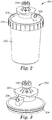
- FIG. 1 shows an example of a dispensing system 100.
- the dispensing system includes a motor base 102 and a container 104 with an integrated pump cap 106.
- the motor base 102 includes a motor (not shown separately) for driving the pump contained in the integrated pump cap 106.
- the motor can be an AC or DC electric motor (e.g., a stepper motor, servo motor, etc.) configured to drive a driveshaft that engages the integrated pump cap 106.
- the motor can be pneumatic, hydraulic, piezo-electric, mechanical (e.g., using a rack and pinion, crankshaft, cam or other similar mechanism), or hand-driven, provided that it is configured to transfer energy to a driveshaft that engages the integrated pump cap 106.
- the motor base 102 can also include a programmable controller, either as a separate unit or as part of the motor itself, such that particular commands can be input in order to, for example, release a specified amount of liquid according to the command.
- the amount can be according to the weight of the liquid dispensed. For example, one command can cause the motor to operate such that one gram of liquid is dispensed. A second command can cause the motor to dispense two grams of liquid and so on.
- a particular liquid can be dispensed in different amounts depending on the application. For example, different liquid colorant amounts can be dispensed depending on the desired color and the amount of plastic material that is to be colored.
- motor commands may be calibrated to dispense a liquid by volume rather than by weight (e.g. a programmed number of milliliters).
- the controller can calculate motor driving time based on a specific flow rate of the pump for a given motor speed. This can depend on the particular liquid being dispensed (e.g., as a function of the viscosity of the liquid). Thus, the motor speed and flow rate can be used to calculate a motor run time to dispense a specified amount (weight or volume) of the liquid.
- the motor base 102 can include an interface for entering commands, e.g., for particular liquid dispensing.
- one or more interface controls can allow the user to specify a particular command using menus, command codes, or a combination of both (e.g., using buttons, touch screen interface, or other input).
- the motor base 102 is coupled to another device that provides a control interface, for example, a computing device.
- the computing device can include software for both controlling the motor base 102 and providing a user interface.
- the user interface can allow the user to provide commands for dispensing liquids.
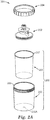
- FIGS. 2 and 2A show a view 201 of an example liquid container 200 with an integrated pump cap 202.
- the liquid container 200 includes a rigid reusable or disposable outer container 203, and a disposable flexible liner 205 positioned within the outer container.
- the outer container can provide structural stability when transporting the liquid container 200.
- the outer container can be removably coupled to the integrated pump cap 202, for example, using a threaded ring 204.
- the threaded ring 204 can be integral to the cap or a separate piece.
- the threads on ring 204 can be either male or female with the complementary mating threads formed on the outer container.
- the threaded ring 204 can also be used to maintain the position of the integrated pump cap 202 on the container 200.
- threaded ring 204 is illustrated in FIG. 2 for removably coupling integrated pump cap 202 to container 200
- other coupling mechanisms may be employed such as, for example, a bayonet connector, snap tabs or snap wings, and the like, which may be useful for providing a "quick connect" capability.
- integrated pump cap 202 may be coupled to container 200 by an interference or friction fit between these two components.
- the integrated pump cap 202 may be coupled to the rigid outer container 203 or the flexible liner 205.
- the coupling mechanisms described above are particularly suited for joining the pump to the rigid outer container. Additional stability can be obtained by, for example, forming the liner with a rim 207 at its open end that rests on the upper edge 209 of the outer container 203. Securing the integrated pump cap to the outer container by the techniques mentioned above may compress the rim of the liner between the upper edge of the outer container and the pump cap.
- integrated pump cap 202 is coupled to the flexible liner this may be accomplished by a friction fit between the pump cap and the liner or by sealing pump cap 202 to the liner using, for example, sonic welding or an adhesive.
- the outer container 203 may contain an air hole 203A that remains open or an air hole that can be opened and closed with, for example, a strip of tape or a valve.
- the inner liner 203 may collapse as liquid is pumped from the container thereby facilitating dispensing all of the liquid.
- the flexible inner liner in combination with the pump cap provides a sealed liquid container that collapses as the liquid is dispensed.
- This ventless construction allows for an air tight dispensing that reduces the risk of contamination to the liquid.
- some liquids can react with oxygen, e.g., liquids that cure when exposed to air.
- Other liquids can easily be contaminated by particulates in the air which can impair their function and also interfere with the dispensing.
- the flexible liner can be composed of various flexible materials, for example, low density polyethylene.
- liquid container 200 is described as including an outer container and an inner liner, it may be a single component in the form of a container without a liner.
- the container that may be rigid or flexible and may contain a vent to equilibrate the pressure inside the container with atmospheric pressure when the vent is open.
- a flexible container may be composed of various flexible polymeric materials, for example, low density polyethylene or, if more strength or durability is desired, an EVA (ethylene vinyl acetate) resin such as Elvax®.
- the integrated pump cap 202 includes a motor coupler 206 that, in the illustrated embodiment, rotates about a central axis in response to a corresponding rotation of a drive component in the motor base 102 shown in FIG. 1 .
- the motor coupler 206 includes a number of teeth that can engage a corresponding set of teeth in the motor base 102.
- the motor coupler 206 is rotated to drive the pump so that contents of the container 200 can be dispensed through an output port 208.
- the teeth can be shaped to facilitate transfer of energy from the motor to the pump. Numerous variations on this approach are possible.
- motor base 102 and motor coupler 206 may have the same number of engagement teeth or a different number of engagement teeth, or they may interact without the use of gears that mesh such as by frictional engagement or magnetic coupling.
- motor transfer rotational energy to the driveshaft it is preferred to have the motor transfer rotational energy to the driveshaft but linear energy transfer can be used too via, for example, a rack and pinion mechanism.
- pump cap 202 may be readily disassembled from motor base 102 without using tools so as to facilitate cleaning and installation of a different container 200.
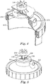
- FIG. 3 shows a view of an example integrated pump cap 300 in more detail.
- the integrated pump cap includes a housing 302, a container coupler 304 (as part of or separate from the housing 302), output port 208, and motor coupler 206.
- the integrated pump cap and its constituent parts may be formed from plastic to achieve a lower manufacturing cost and to allow for easy disposability, but if the nature of the materials to be pumped or other circumstances warrant, the integrated pump cap may be formed of metal, or a combination of metal and plastic components.
- pump cap housing 302 may be formed as a single piece or as a combination of pieces that are removably attached together or that are fixed together (e.g., by sonic welding).
- a portion of the housing 302 can be a lid configured to fit container 200 (either the outer container or the liner).
- a portion of the lid can be removed in order to form an aperture in which to couple a pump housing including the pump for dispensing fluid from the container.
- the pump housing includes a first portion positioned on one side of the lid aperture and a second portion positioned on the other side of the lid aperture, where the two portions are configured to engage in order to lock the portions together and to the lid.
- An o-ring or other seal or gasket can be positioned between the lid and a portion of the pump housing to prevent liquid leaks.
- the pump housing is joined to the lid (e.g., by sonic welding or using an adhesive) to bond the pump housing to the lid.
- the pump housing can be integrally formed with a lid for closing the container.
- the container coupler 304 allows the integrated pump cap 300 to attach to the container 200 ( FIG. 2 ).
- the container coupler 304 is in the form of male or female threads that join with complementary threads formed on container 200.
- the container coupler 304 is configured to provide an interference or friction fit with the container.
- the container coupler 304 may be a bayonet connector, snap tabs, snap wings or the like (with complementary engaging structure formed on the container), which may be useful for providing a "quick connect" capability.
- the container coupler 304 may be provided as a weld (e.g., a sonic weld) or as an adhesive that joins the pump cap 300 to the container.
- the output port 208 is configured to output liquids from the container as driven by the pump in the pump cap 300. The pump is driven using the motor coupler 206.
- FIG. 4 shows a cutaway view 400 of the example integrated pump cap to illustrate additional details.
- the cutaway view 400 shows the motor coupler 206, output port 208, a container 402 coupled to the integrated pump cap using thread ring 204, and a partial view of pump 404.
- the pump 404 is a G-rotor pump but as noted above many other types of pumps, including a peristaltic pump, a syringe pump, or an elastomeric diaphragm pump may be used instead.
- the pump can be formed from metal, plastic, other materials, or combinations thereof.
- the pump housing is molded or otherwise fabricated from glass-filled nylon, and the gears are molded or otherwise fabricated from a polytetrafluoroethylne (e.g., TeflonTM)-impregnated acetal.
- TeflonTM polytetrafluoroethylne
- the integrated pump cap is mounted to the motor such that the motor coupler 206 is coupled to the motor at a downward orientation; that is, in its use position, the motor coupler is above the motor, as shown in FIG 1 .
- the container is positioned above the pump 404 such that the liquid is gravitationally directed to an input of the pump 404.
- FIG. 5 shows another cutaway view 500 of the integrated pump cap.
- the G-rotor pump 404 is exposed from the top while other portions of a housing 502 arc intact.
- the motor coupler 206 is coupled to a shaft 504.
- the shaft 504 is further coupled to an inner or first rotor 506.
- the inner rotor 506 sits off center within and engages an outer or second rotor 508.
- the shaft 504 rotates. Rotation of the shaft 504 causes the inner rotor 506 to rotate within the outer rotor 508.
- the outer rotor 508 has more slots than the number of rotor lobes on the inner rotor 506 such that the inner rotor 506 rotates in an eccentric manner with the outer rotor 508. This rotation is such that in a first position an input port is exposed allowing fluid to flow from the container into a space between the lobes of the inner rotor 506. As the inner rotor 506 and outer rotor 508 continue to rotate, an output is exposed between the lobes and the liquid is pushed out of the pump through output port 208.
- the outer rotor 508 revolves at a slower rate than the inner rotor 506, thereby rotating and changing the volume of the chambers created by the slots.
- the pump is reversible allowing liquids to be pumped from outside the container through the output port 208 (which in this configuration may be regarded as an input port) and into a container.
- the pump is non-reversible such that liquids can only be pumped out of the container.
- FIG. 6 shows a cross-sectional view 600 of the exemplary integrated pump cap in more detail.
- the cross-sectional view 600 illustrates the motor coupler 206, shaft 504, G-rotor pump 404, and housing 302.
- the G-rotor pump 404 is disk shaped from the side and is intersected by the shaft 504 off-center.
- the outer rotor 508 ( FIG. 5 ) is intersected off-center while the inner rotor 506 ( FIG. 5 ) is intersected by the shaft 504 substantially in the center.
- This off-center drive shaft 504 allows for the eccentric rotation of the G-rotor pump components.
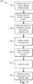
- FIG. 7 shows a flow diagram of an example process 700 for dispensing liquids.
- the process 700 will be described with respect to a dispensing system that performs the process 700.
- the dispensing system receives a selected liquid container with an integrated pump (702).
- the dispensing system can be used to dispense a number of different liquids including any of those mentioned hereinabove.
- the liquids and their respective containers can be interchanged.
- different colors can be used with the dispensing system in order to provide different colors.
- Receiving a selected liquid container can include coupling the liquid container with the integrated pump to a motor.
- the motor can include a drive shaft coupler configured to receive a motor coupler of the integrated pump. Additional couplings can also be performed.
- an output port of the integrated pump can be coupled to a destination (e.g., a container, machine, or other location), for example, with a tube or other liquid pathway.
- the dispensing system determines an amount of liquid to dispense (704).
- the amount to dispense can be determined, for example, in response to a user input to an interface of the dispensing system.
- the user can input a specific time to dispense, amount to dispense, or a command code that corresponds to a specific programmed amount to dispense.
- the input command code can be specific to the liquid to be dispensed.
- the input command code can be specific to the application of the dispensed liquid (e.g., an amount necessary to color a particular volume of neutral colored plastic in an injection molding apparatus).
- the dispensing system activates a motor to dispense liquid (706).
- the motor is activated in order to drive the integrated pump.
- the motor rotates or otherwise moves a drive shaft that causes a corresponding rotation or other movement of the integrated pump components such that precise amounts of fluid are dispensed as a function of the motor speed, pump configuration, and liquid being dispensed.
- the dispensing system deactivates the motor to finish dispensing liquid (708).
- the motor is deactivated to stop the integrated pump.
- the dispensing system can be calibrated to account for any residual liquid between the pump output and the destination (e.g., in a dispensing tube) that will be released so that substantially the exact amount of liquid is dispensed once the motor is deactivated.
- the dispensed liquid can then be used for various applications.
- FIG. 8 shows a block diagram of an example injection molding system 800.
- the injection molding system 800 includes base plastic material 802 (e.g., beads or pellets of a resin in a hopper) and liquid colorant 804 or other liquid (e.g., in a container including an integrated pump for dispensing precise amounts of liquid as described above).
- base plastic material 802 e.g., beads or pellets of a resin in a hopper
- liquid colorant 804 or other liquid e.g., in a container including an integrated pump for dispensing precise amounts of liquid as described above.
- the plastic material 802 and liquid colorant 804 arc provided to an injection molding device 806.
- the injection molding device 806 includes a heater 808 and a mold 810.
- the heater 808 melts the plastic material 802 and into which the liquid colorant 804 can be added.
- the melted plastic material 802 can be injected into the mold 810.
- the mold has a shape formed within the mold cavity corresponding to a desired output colored molded plastic 812.
- Other molding systems may be used and their operational principles can be understood from the block diagram of FIG. 8 too.
- injection molding device 806 may be a blow molding, an injection blow molding, an extrusion molding, or a rotational molding device and mold 810 may be provided by an extrusion die or head to yield a plastic component having a desired profile.
- FIG. 9 shows a flow diagram of an example process 900 for dispensing colorants in an injection molding system.
- a colorant is identified to add to injected molded plastic in order to produce molded plastic of a particular color (902).
- the colorant is coupled to an injection molding device (904).
- an output port of an integrated pump cap for a colorant container can be coupled to an input of the injection molding device.
- a dosing amount of colorant for each injection molding cycle is determined (906). For example, a user can input parameters to the injection molding device or to a control interface for a motor that drives the pump of the integrated pump cap. In some implementations, commands are associated with a timing cycle for the injection molding machine such that the precise amount of colorant can be dosed for each molding cycle.
- the injection molding cycle is initiated (908). Initiating an injection molding cycle can include releasing base plastic material from a hopper into a heating portion of the injection molding device to melt the base plastic material. The determined dose of liquid colorant is added to the melting or melted base plastic material (910).
- the liquid dispenser can be used to dispense liquid colorant for use in a variety of processes including extrusion, blow molding, film production, etc.
- liquid colorants can be used to color various products (e.g., bottles).
- processing commands for a motor to drive a pump to dispense a specified amount of liquid can be implemented as operations performed by a data processing apparatus on data stored on one or more computer-readable storage devices or received from other sources.
- the term "data processing apparatus” encompasses all kinds of apparatus, devices, and machines for processing data, including by way of example a programmable processor, a computer, a system on a chip, or multiple ones, or combinations of the foregoing.
- the apparatus can include special purpose logic circuitry, e.g., an FPGA (field programmable gate array) or an ASIC (application-specific integrated circuit).
- the apparatus can also include, in addition to hardware, code that creates an execution environment for the computer program in question; e.g., code that constitutes processor firmware, a protocol stack, a database management system, an operating system, a cross-platform runtime environment, a virtual machine, or a combination of one or more of these.
- the apparatus and execution environment can realize various different computing model infrastructures, such as web services, distributed computing and grid computing infrastructures.
- a computer program (also known as a program, software, software application, script, or code) can be written in any form of programming language, including compiled or interpreted languages, declarative or procedural languages, and it can be deployed in any form, including as a stand-alone program or as a module, component, subroutine, object, or other unit suitable for use in a computing environment.
- a computer program can be deployed to be executed on one computer or on multiple computers that are located at one site or distributed across multiple sites and interconnected by a communication network.
- the program instructions can be encoded on or can be included in a computer storage medium, a computer-readable storage device, a computer-readable storage substrate, a random or serial access memory array or device, or a combination of one or more of these.
- a computer storage medium is not a propagated signal, a computer storage medium can be a source or destination of computer program instructions encoded in an artificially generated propagated signal.
- the computer storage medium can also be, or be included in, one or more separate physical components or media (e.g., multiple CDs, disks, or other storage devices).
- the processes and logic flows described in this specification can be performed by one or more programmable processors executing one or more computer programs to perform actions by operating on input data and generating output.
- the processes and logic flows can also be performed by, and apparatus can also be implemented as, special purpose logic circuitry, e.g., an FPGA (field programmable gate array) or an ASIC (application-specific integrated circuit).
- processors suitable for the execution of a computer program include, by way of example, both general and special purpose microprocessors, and any one or more processors of any kind of digital computer.
- a processor will receive instructions and data from a read-only memory or a random access memory or both.
- the essential elements of a computer are a processor for performing actions in accordance with instructions and one or more memory devices for storing instructions and data.
- Non-volatile memory media and memory devices, including by way of example semiconductor memory devices, e.g., EPROM, EEPROM, and flash memory devices; magnetic disks, e.g., internal hard disks or removable disks; magneto-optical disks; and CD-ROM and DVD-ROM disks.
- semiconductor memory devices e.g., EPROM, EEPROM, and flash memory devices
- magnetic disks e.g., internal hard disks or removable disks
- magneto-optical disks e.g., CD-ROM and DVD-ROM disks.
- a computer having a display device, e.g., a CRT (cathode ray tube) or LCD (liquid crystal display) monitor, for displaying information to the user and a keyboard and a pointing device, e.g., a mouse or a trackball, by which the user can provide input to the computer.
- a display device e.g., a CRT (cathode ray tube) or LCD (liquid crystal display) monitor
- keyboard and a pointing device e.g., a mouse or a trackball
- Other kinds of devices can be used to provide for interaction with a user as well; for example, feedback provided to the user can be any form of sensory feedback, e.g., visual feedback, auditory feedback, or tactile feedback; and input from the user can be received in any form, including acoustic, speech, or tactile input.
- a computer can interact with a user by sending documents to and receiving documents from a device that is used by the user; for example, by sending web pages to a
- the method of producing a colored plastic article according to the invention may include a step for dispensing a specified amount of liquid colorant comprising: receiving a command to dispense a specified amount of liquid colorant; initiating a motor coupled to a liquid container, the liquid container including a pump in an integrated pump cap; and stopping the motor when the specified amount of liquid colorant has been dispensed from the liquid container.
- the liquid container may comprise an outer container and an inner liner.
- the outer container may be rigid and the inner liner may be flexible.
- the rigid outer container may have an air hole and the flexible inner liner may collapse as liquid colorant is withdrawn from the liquid container.
- the liquid container may be pressurized and is positioned above the integrated pump cap when liquid colorant is being dispensed from the liquid container.
- the liquid colorant flows from the liquid container under the force of gravity during use.
- the liquid container is positioned above the motor when liquid colorant is being dispensed from the liquid container.
- the integrated pump cap may be removably coupled to the liquid container.
- the integrated pump cap may be removably coupled to the liquid container by a threaded ring.
- the threaded ring may engage corresponding threads on the liquid container.
- the integrated pump cap may also be removably coupled to the liquid container by a quick connector, or may be coupled to the liquid container by a weld or an adhesive.
- the amount of liquid that is dispensed from the liquid container may be based on the weight of the liquid or may be based on the volume of the liquid.
- the pump may be a G-rotor pump, a peristaltic pump, a syringe pump, or an elastic diaphragm pump.
- the motor may be an electric motor, a pneumatic motor, a hydraulic motor, a piezo-electric motor, or a mechanical motor.
- the motor may transfer rotational or linear energy to the motor coupler.
- the integrated pump cap may further include a first rotor that is coupled to a shaft that is coupled to the motor coupler.
- the integrated pump cap may further include a second rotor that moves in response to movement of the first rotor.
- the first rotor may include at least one lobe and the second rotor may include at least one slot, the at least one lobe on the first rotor engaging the at least one slot on the second rotor to move the second rotor in response to movement of the first rotor, and wherein the number of lobes on the first rotor is different than the number of slots on the second rotor.
- the shaft may intersect the first rotor substantially in the center thereof and the second rotor off-center thereof.
- the motor may further include a controller that can be programmed to control operation of the motor.
- the device may be a molding apparatus, and the molding apparatus may be an injection molding apparatus, an injection blow molding apparatus, a blow molding apparatus, or an extrusion head.
- the molding apparatus may further include a heater for melting plastic resin.
- the liquid colorant is used to color plastic resin that is received by the molding apparatus.
- the plastic resin has a neutral color and the amount of liquid colorant that is dispensed may be selected to impart a tailored color to the plastic resin.
Landscapes
- Engineering & Computer Science (AREA)
- Mechanical Engineering (AREA)
- Manufacturing & Machinery (AREA)
- Containers And Packaging Bodies Having A Special Means To Remove Contents (AREA)
- Loading And Unloading Of Fuel Tanks Or Ships (AREA)
- Closures For Containers (AREA)
- Injection Moulding Of Plastics Or The Like (AREA)
- Structures Of Non-Positive Displacement Pumps (AREA)
- Coating Apparatus (AREA)
Priority Applications (1)
| Application Number | Priority Date | Filing Date | Title |
|---|---|---|---|
| PL16189824T PL3135452T3 (pl) | 2010-10-08 | 2011-10-07 | Sposób wytwarzania kolorowego wyrobu z tworzywa sztucznego |
Applications Claiming Priority (2)
| Application Number | Priority Date | Filing Date | Title |
|---|---|---|---|
| US39154910P | 2010-10-08 | 2010-10-08 | |
| EP11770657.2A EP2625017B1 (en) | 2010-10-08 | 2011-10-07 | Method and device for dispensing liquids from a container coupled to an integrated pump cap |
Related Parent Applications (2)
| Application Number | Title | Priority Date | Filing Date |
|---|---|---|---|
| EP11770657.2A Division EP2625017B1 (en) | 2010-10-08 | 2011-10-07 | Method and device for dispensing liquids from a container coupled to an integrated pump cap |
| EP11770657.2A Division-Into EP2625017B1 (en) | 2010-10-08 | 2011-10-07 | Method and device for dispensing liquids from a container coupled to an integrated pump cap |
Publications (2)
| Publication Number | Publication Date |
|---|---|
| EP3135452A1 EP3135452A1 (en) | 2017-03-01 |
| EP3135452B1 true EP3135452B1 (en) | 2018-07-04 |
Family
ID=44802444
Family Applications (2)
| Application Number | Title | Priority Date | Filing Date |
|---|---|---|---|
| EP16189824.2A Active EP3135452B1 (en) | 2010-10-08 | 2011-10-07 | Method of producing a colored plastic article |
| EP11770657.2A Active EP2625017B1 (en) | 2010-10-08 | 2011-10-07 | Method and device for dispensing liquids from a container coupled to an integrated pump cap |
Family Applications After (1)
| Application Number | Title | Priority Date | Filing Date |
|---|---|---|---|
| EP11770657.2A Active EP2625017B1 (en) | 2010-10-08 | 2011-10-07 | Method and device for dispensing liquids from a container coupled to an integrated pump cap |
Country Status (12)
Cited By (1)
| Publication number | Priority date | Publication date | Assignee | Title |
|---|---|---|---|---|
| GB2592932B (en) * | 2020-03-10 | 2025-01-29 | Colormatrix Holdings Inc | Polymeric materials |
Families Citing this family (9)
| Publication number | Priority date | Publication date | Assignee | Title |
|---|---|---|---|---|
| JP2020527513A (ja) * | 2017-06-26 | 2020-09-10 | スリーエム イノベイティブ プロパティズ カンパニー | 実質的に液体のみが容器内に配置されることを保証するための液体添加剤供給システム及び方法 |
| USD898868S1 (en) | 2018-09-12 | 2020-10-13 | 3M Innovative Properties Company | Liquid delivery system lid |
| USD919045S1 (en) | 2018-09-12 | 2021-05-11 | 3M Innovative Properties Company | Liquid delivery system coupler |
| USD918339S1 (en) | 2018-09-12 | 2021-05-04 | 3M Innovative Properties Company | Liquid delivery system cup |
| CN114340868A (zh) * | 2019-09-05 | 2022-04-12 | 3M创新有限公司 | 递送用于模塑的添加剂的方法和系统 |
| US11866915B2 (en) * | 2020-12-07 | 2024-01-09 | Rheem Manufacturing Company | Liquid concentrate dosing systems |
| US12139429B2 (en) * | 2020-12-07 | 2024-11-12 | Rheem Manufacturing Company | Scaling treatment systems for water heaters |
| GB2609594B (en) * | 2021-05-05 | 2024-12-11 | Psg Germany Gmbh | Devices for dispensing fluids |
| US12269729B2 (en) | 2023-01-27 | 2025-04-08 | Vgp Ipco Llc | Reusable or refillable container for dispensing motor oil |
Family Cites Families (43)
| Publication number | Priority date | Publication date | Assignee | Title |
|---|---|---|---|---|
| US2413710A (en) * | 1943-12-11 | 1947-01-07 | Sprayer Corp | Spraying apparatus |
| US2619292A (en) * | 1949-11-29 | 1952-11-25 | Du Pont | Slurry pump with screened discharge for preventing lump accumulation |
| US2651545A (en) * | 1950-05-31 | 1953-09-08 | John C Shotton | Paint spray attachment device |
| US3993250A (en) * | 1975-05-19 | 1976-11-23 | Shure Alan H | Apparatus for spraying liquid materials |
| US4135647A (en) * | 1977-09-21 | 1979-01-23 | The Continental Group, Inc. | Motor driven dispensing unit for containers |
| US4187959A (en) * | 1978-08-17 | 1980-02-12 | The Continental Group, Inc. | Propellantless aerosol dispensing system |
| US4570833A (en) * | 1983-08-26 | 1986-02-18 | Vanderjagt John A | Pumping system |
| US4583487A (en) * | 1983-09-02 | 1986-04-22 | Wood Horace G | Method and apparatus for cyclically dispensing lubricants and colorings for use in injection molding machines |
| US4735345A (en) * | 1986-04-24 | 1988-04-05 | Lee Fu Kuei | Water supply device of vacuum bottle |
| DE3916021A1 (de) * | 1988-10-25 | 1990-11-22 | Wunsch Erich | Spraydose |
| US4987975A (en) * | 1990-04-17 | 1991-01-29 | Liu Chen C | Portable automobile grease suction machine |
| US6460734B1 (en) * | 1990-06-06 | 2002-10-08 | Lancer Partnership | Dispensing apparatus including a pump package system |
| US5301838A (en) * | 1991-01-23 | 1994-04-12 | Continental Pet Technologies, Inc. | Multilayer bottle with separable inner layer and method for forming same |
| FR2672279B1 (fr) * | 1991-02-05 | 1996-05-24 | Georges Gruffy | Installation de distribution de produit liquide ou pateux et conditionnement d'un tel produit pour une telle installation. |
| US5797519A (en) * | 1997-03-14 | 1998-08-25 | The Coca-Cola Company | Postmix beverage dispenser |
| US5836482A (en) * | 1997-04-04 | 1998-11-17 | Ophardt; Hermann | Automated fluid dispenser |
| US6142750A (en) * | 1998-11-30 | 2000-11-07 | The Procter & Gamble Company | Gear pump and replaceable reservoir for a fluid sprayer |
| JP2001090749A (ja) * | 1999-07-30 | 2001-04-03 | Dana Corp | 流体圧式リミテッド・スリップ・ディファレンシャル及びディファレンシャル用ジロータ・ポンプ |
| US6254363B1 (en) * | 2000-01-20 | 2001-07-03 | M. A. Hannacolor, A Division Of M. A. Hanna Company | Liquid colorant tube assembly |
| US6343724B1 (en) * | 2000-07-10 | 2002-02-05 | Hygiene Technik Inc. | Unitary one-way valve for fluid dispenser |
| JP3987273B2 (ja) * | 2000-08-01 | 2007-10-03 | 理想科学工業株式会社 | インキ容器 |
| US20050052945A1 (en) * | 2002-01-31 | 2005-03-10 | Maguire Stephen B. | Method and apparatus for storing and delivering liquid color material |
| CA2381868C (en) * | 2002-04-16 | 2009-09-01 | Hygiene-Technik Inc. | Vacuum relief device |
| US7198175B2 (en) * | 2002-04-26 | 2007-04-03 | Heiner Ophardt | Manual or pump assist fluid dispenser |
| US7837132B2 (en) * | 2002-05-28 | 2010-11-23 | S.C. Johnson & Son, Inc. | Automated cleansing sprayer |
| US7845582B2 (en) * | 2002-12-18 | 2010-12-07 | 3M Innovative Properties Company | Spray gun reservoir with oversize, fast-fill opening |
| US6890161B2 (en) * | 2003-03-31 | 2005-05-10 | Assistive Technology Products, Inc. | Disposable fluid delivery system |
| US20050139612A1 (en) * | 2003-12-30 | 2005-06-30 | Matthews Shaun K. | Foam dispenser |
| CN103010595B (zh) * | 2005-04-25 | 2015-01-14 | 高级技术材料公司 | 容纳液体或含液体物质的衬、容器及方法 |
| US20060278657A1 (en) * | 2005-06-14 | 2006-12-14 | Roatis Calin V | Concentrate dispensing units and disposable concentrate packages including impeller pumps |
| DE202005015569U1 (de) * | 2005-10-05 | 2006-01-26 | Krauss-Maffei Kunststofftechnik Gmbh | Zuschlagsstoff-Dosiervorrichtung für Polyurethan-Anlage |
| JP4754329B2 (ja) * | 2005-11-15 | 2011-08-24 | Ntn株式会社 | 含油樹脂成形体の製造方法 |
| EP1806314A1 (en) * | 2006-01-09 | 2007-07-11 | Nestec S.A. | Device for dispensing a beverage with a controlled air inlet, and method therefor |
| GB0625896D0 (en) * | 2006-12-23 | 2007-02-07 | Colormatrix Holdings Inc | Apparatus for delivering a fluid and methods relating thereto |
| WO2008103300A2 (en) * | 2007-02-16 | 2008-08-28 | Gojo Industries, Inc. | Flexible impeller pumps for mixing individual components |
| US20080277421A1 (en) * | 2007-05-08 | 2008-11-13 | Doug Zlatic | Gear pump and foam dispenser |
| EP2017220B1 (en) * | 2007-07-19 | 2010-09-15 | Nestec, Ltd. | Device for dispensing a liquid |
| DE602007008873D1 (de) * | 2007-07-19 | 2010-10-14 | Nestec Ltd | Vorrichtung zur Abgabe einer Flüssigkeit |
| CA2703965C (en) * | 2007-10-23 | 2014-02-11 | Technical Concepts, Llc | Dispenser with draw-back mechanism |
| US8360278B2 (en) * | 2007-12-05 | 2013-01-29 | Freeze King | Pressure vessel, system and/or method for dispensing a comestible mixture |
| CA2620709C (en) * | 2008-02-08 | 2017-02-28 | Gotohti.Com Inc. | Rotary foam pump |
| US8272537B2 (en) * | 2008-04-17 | 2012-09-25 | Nordson Corporation | Valveless liquid dispenser |
| KR101694597B1 (ko) * | 2008-10-22 | 2017-01-09 | 그라코 미네소타 인크. | 휴대용 에어리스 스프레이어 |
-
2011
- 2011-10-07 CA CA2813573A patent/CA2813573C/en not_active Expired - Fee Related
- 2011-10-07 RU RU2013115055/12A patent/RU2596471C2/ru active
- 2011-10-07 WO PCT/US2011/055184 patent/WO2012048172A1/en active Application Filing
- 2011-10-07 US US13/878,259 patent/US20130270303A1/en not_active Abandoned
- 2011-10-07 EP EP16189824.2A patent/EP3135452B1/en active Active
- 2011-10-07 ES ES16189824.2T patent/ES2687423T3/es active Active
- 2011-10-07 PL PL11770657T patent/PL2625017T3/pl unknown
- 2011-10-07 MX MX2013003813A patent/MX341794B/es active IP Right Grant
- 2011-10-07 EP EP11770657.2A patent/EP2625017B1/en active Active
- 2011-10-07 ES ES11770657T patent/ES2701029T3/es active Active
- 2011-10-07 PL PL16189824T patent/PL3135452T3/pl unknown
- 2011-10-07 JP JP2013532962A patent/JP5997165B2/ja not_active Expired - Fee Related
- 2011-10-07 AU AU2011311911A patent/AU2011311911B2/en not_active Ceased
- 2011-10-07 BR BR112013008303-4A patent/BR112013008303B1/pt not_active IP Right Cessation
- 2011-10-07 CN CN201180048466.3A patent/CN103153574B/zh not_active Expired - Fee Related
-
2019
- 2019-10-30 US US16/669,216 patent/US20200062581A1/en not_active Abandoned
Non-Patent Citations (1)
| Title |
|---|
| None * |
Cited By (1)
| Publication number | Priority date | Publication date | Assignee | Title |
|---|---|---|---|---|
| GB2592932B (en) * | 2020-03-10 | 2025-01-29 | Colormatrix Holdings Inc | Polymeric materials |
Also Published As
| Publication number | Publication date |
|---|---|
| EP2625017A1 (en) | 2013-08-14 |
| JP5997165B2 (ja) | 2016-09-28 |
| BR112013008303A2 (pt) | 2020-08-25 |
| AU2011311911A1 (en) | 2013-05-02 |
| MX341794B (es) | 2016-09-02 |
| AU2011311911B2 (en) | 2015-06-11 |
| CA2813573C (en) | 2021-05-25 |
| US20200062581A1 (en) | 2020-02-27 |
| PL3135452T3 (pl) | 2019-01-31 |
| ES2701029T3 (es) | 2019-02-20 |
| CA2813573A1 (en) | 2012-04-12 |
| PL2625017T3 (pl) | 2019-04-30 |
| RU2013115055A (ru) | 2014-11-20 |
| EP2625017B1 (en) | 2018-09-26 |
| CN103153574B (zh) | 2016-06-08 |
| WO2012048172A1 (en) | 2012-04-12 |
| MX2013003813A (es) | 2013-05-01 |
| RU2596471C2 (ru) | 2016-09-10 |
| BR112013008303B1 (pt) | 2021-04-27 |
| CN103153574A (zh) | 2013-06-12 |
| JP2014501665A (ja) | 2014-01-23 |
| US20130270303A1 (en) | 2013-10-17 |
| EP3135452A1 (en) | 2017-03-01 |
| ES2687423T3 (es) | 2018-10-25 |
Similar Documents
| Publication | Publication Date | Title |
|---|---|---|
| EP3135452B1 (en) | Method of producing a colored plastic article | |
| US20220072748A1 (en) | Liquid additive delivery system and methods for ensuring substantially only a liquid is disposed within a container | |
| US20220314508A1 (en) | Method and system of delivering additives for molding | |
| US20240116015A1 (en) | Personal Cosmetic Dispenser | |
| US20150176577A1 (en) | Hemi-Toroidal Fluid Pump | |
| US10138881B2 (en) | Fluid pump with pulse reduction | |
| CN209093314U (zh) | 消毒液间歇加料装置和消毒液生产设备 | |
| CN208964521U (zh) | 一种灌装机 | |
| CN208632083U (zh) | 一种液体灌装器 | |
| KR20210116910A (ko) | 정량 액상 충진 시스템 및 그 충진 방법 | |
| KR100430909B1 (ko) | 액상 내용물의 정량 주입장치 | |
| WO2017185107A1 (en) | Apparatus and method for dosing an additive into a metered flow of material | |
| BRPI1000608A2 (pt) | bamba de engrenagens automatizada com múltiplas funções |
Legal Events
| Date | Code | Title | Description |
|---|---|---|---|
| PUAI | Public reference made under article 153(3) epc to a published international application that has entered the european phase |
Free format text: ORIGINAL CODE: 0009012 |
|
| STAA | Information on the status of an ep patent application or granted ep patent |
Free format text: STATUS: REQUEST FOR EXAMINATION WAS MADE |
|
| 17P | Request for examination filed |
Effective date: 20161020 |
|
| AC | Divisional application: reference to earlier application |
Ref document number: 2625017 Country of ref document: EP Kind code of ref document: P |
|
| AK | Designated contracting states |
Kind code of ref document: A1 Designated state(s): AL AT BE BG CH CY CZ DE DK EE ES FI FR GB GR HR HU IE IS IT LI LT LU LV MC MK MT NL NO PL PT RO RS SE SI SK SM TR |
|
| GRAP | Despatch of communication of intention to grant a patent |
Free format text: ORIGINAL CODE: EPIDOSNIGR1 |
|
| STAA | Information on the status of an ep patent application or granted ep patent |
Free format text: STATUS: GRANT OF PATENT IS INTENDED |
|
| INTG | Intention to grant announced |
Effective date: 20180122 |
|
| GRAS | Grant fee paid |
Free format text: ORIGINAL CODE: EPIDOSNIGR3 |
|
| GRAA | (expected) grant |
Free format text: ORIGINAL CODE: 0009210 |
|
| STAA | Information on the status of an ep patent application or granted ep patent |
Free format text: STATUS: THE PATENT HAS BEEN GRANTED |
|
| AC | Divisional application: reference to earlier application |
Ref document number: 2625017 Country of ref document: EP Kind code of ref document: P |
|
| AK | Designated contracting states |
Kind code of ref document: B1 Designated state(s): AL AT BE BG CH CY CZ DE DK EE ES FI FR GB GR HR HU IE IS IT LI LT LU LV MC MK MT NL NO PL PT RO RS SE SI SK SM TR |
|
| REG | Reference to a national code |
Ref country code: GB Ref legal event code: FG4D |
|
| REG | Reference to a national code |
Ref country code: CH Ref legal event code: EP |
|
| REG | Reference to a national code |
Ref country code: AT Ref legal event code: REF Ref document number: 1014027 Country of ref document: AT Kind code of ref document: T Effective date: 20180715 |
|
| REG | Reference to a national code |
Ref country code: IE Ref legal event code: FG4D |
|
| REG | Reference to a national code |
Ref country code: DE Ref legal event code: R096 Ref document number: 602011049888 Country of ref document: DE |
|
| REG | Reference to a national code |
Ref country code: FR Ref legal event code: PLFP Year of fee payment: 8 |
|
| REG | Reference to a national code |
Ref country code: ES Ref legal event code: FG2A Ref document number: 2687423 Country of ref document: ES Kind code of ref document: T3 Effective date: 20181025 |
|
| REG | Reference to a national code |
Ref country code: NL Ref legal event code: MP Effective date: 20180704 |
|
| REG | Reference to a national code |
Ref country code: LT Ref legal event code: MG4D |
|
| REG | Reference to a national code |
Ref country code: AT Ref legal event code: MK05 Ref document number: 1014027 Country of ref document: AT Kind code of ref document: T Effective date: 20180704 |
|
| PG25 | Lapsed in a contracting state [announced via postgrant information from national office to epo] |
Ref country code: NL Free format text: LAPSE BECAUSE OF FAILURE TO SUBMIT A TRANSLATION OF THE DESCRIPTION OR TO PAY THE FEE WITHIN THE PRESCRIBED TIME-LIMIT Effective date: 20180704 |
|
| PG25 | Lapsed in a contracting state [announced via postgrant information from national office to epo] |
Ref country code: AT Free format text: LAPSE BECAUSE OF FAILURE TO SUBMIT A TRANSLATION OF THE DESCRIPTION OR TO PAY THE FEE WITHIN THE PRESCRIBED TIME-LIMIT Effective date: 20180704 Ref country code: IS Free format text: LAPSE BECAUSE OF FAILURE TO SUBMIT A TRANSLATION OF THE DESCRIPTION OR TO PAY THE FEE WITHIN THE PRESCRIBED TIME-LIMIT Effective date: 20181104 Ref country code: SE Free format text: LAPSE BECAUSE OF FAILURE TO SUBMIT A TRANSLATION OF THE DESCRIPTION OR TO PAY THE FEE WITHIN THE PRESCRIBED TIME-LIMIT Effective date: 20180704 Ref country code: BG Free format text: LAPSE BECAUSE OF FAILURE TO SUBMIT A TRANSLATION OF THE DESCRIPTION OR TO PAY THE FEE WITHIN THE PRESCRIBED TIME-LIMIT Effective date: 20181004 Ref country code: GR Free format text: LAPSE BECAUSE OF FAILURE TO SUBMIT A TRANSLATION OF THE DESCRIPTION OR TO PAY THE FEE WITHIN THE PRESCRIBED TIME-LIMIT Effective date: 20181005 Ref country code: RS Free format text: LAPSE BECAUSE OF FAILURE TO SUBMIT A TRANSLATION OF THE DESCRIPTION OR TO PAY THE FEE WITHIN THE PRESCRIBED TIME-LIMIT Effective date: 20180704 Ref country code: LT Free format text: LAPSE BECAUSE OF FAILURE TO SUBMIT A TRANSLATION OF THE DESCRIPTION OR TO PAY THE FEE WITHIN THE PRESCRIBED TIME-LIMIT Effective date: 20180704 Ref country code: NO Free format text: LAPSE BECAUSE OF FAILURE TO SUBMIT A TRANSLATION OF THE DESCRIPTION OR TO PAY THE FEE WITHIN THE PRESCRIBED TIME-LIMIT Effective date: 20181004 Ref country code: CZ Free format text: LAPSE BECAUSE OF FAILURE TO SUBMIT A TRANSLATION OF THE DESCRIPTION OR TO PAY THE FEE WITHIN THE PRESCRIBED TIME-LIMIT Effective date: 20180704 Ref country code: FI Free format text: LAPSE BECAUSE OF FAILURE TO SUBMIT A TRANSLATION OF THE DESCRIPTION OR TO PAY THE FEE WITHIN THE PRESCRIBED TIME-LIMIT Effective date: 20180704 |
|
| PG25 | Lapsed in a contracting state [announced via postgrant information from national office to epo] |
Ref country code: HR Free format text: LAPSE BECAUSE OF FAILURE TO SUBMIT A TRANSLATION OF THE DESCRIPTION OR TO PAY THE FEE WITHIN THE PRESCRIBED TIME-LIMIT Effective date: 20180704 Ref country code: LV Free format text: LAPSE BECAUSE OF FAILURE TO SUBMIT A TRANSLATION OF THE DESCRIPTION OR TO PAY THE FEE WITHIN THE PRESCRIBED TIME-LIMIT Effective date: 20180704 Ref country code: AL Free format text: LAPSE BECAUSE OF FAILURE TO SUBMIT A TRANSLATION OF THE DESCRIPTION OR TO PAY THE FEE WITHIN THE PRESCRIBED TIME-LIMIT Effective date: 20180704 |
|
| REG | Reference to a national code |
Ref country code: DE Ref legal event code: R097 Ref document number: 602011049888 Country of ref document: DE |
|
| PG25 | Lapsed in a contracting state [announced via postgrant information from national office to epo] |
Ref country code: RO Free format text: LAPSE BECAUSE OF FAILURE TO SUBMIT A TRANSLATION OF THE DESCRIPTION OR TO PAY THE FEE WITHIN THE PRESCRIBED TIME-LIMIT Effective date: 20180704 Ref country code: EE Free format text: LAPSE BECAUSE OF FAILURE TO SUBMIT A TRANSLATION OF THE DESCRIPTION OR TO PAY THE FEE WITHIN THE PRESCRIBED TIME-LIMIT Effective date: 20180704 |
|
| PLBE | No opposition filed within time limit |
Free format text: ORIGINAL CODE: 0009261 |
|
| STAA | Information on the status of an ep patent application or granted ep patent |
Free format text: STATUS: NO OPPOSITION FILED WITHIN TIME LIMIT |
|
| PG25 | Lapsed in a contracting state [announced via postgrant information from national office to epo] |
Ref country code: SM Free format text: LAPSE BECAUSE OF FAILURE TO SUBMIT A TRANSLATION OF THE DESCRIPTION OR TO PAY THE FEE WITHIN THE PRESCRIBED TIME-LIMIT Effective date: 20180704 Ref country code: DK Free format text: LAPSE BECAUSE OF FAILURE TO SUBMIT A TRANSLATION OF THE DESCRIPTION OR TO PAY THE FEE WITHIN THE PRESCRIBED TIME-LIMIT Effective date: 20180704 Ref country code: SK Free format text: LAPSE BECAUSE OF FAILURE TO SUBMIT A TRANSLATION OF THE DESCRIPTION OR TO PAY THE FEE WITHIN THE PRESCRIBED TIME-LIMIT Effective date: 20180704 |
|
| REG | Reference to a national code |
Ref country code: CH Ref legal event code: PL |
|
| 26N | No opposition filed |
Effective date: 20190405 |
|
| REG | Reference to a national code |
Ref country code: BE Ref legal event code: MM Effective date: 20181031 |
|
| PG25 | Lapsed in a contracting state [announced via postgrant information from national office to epo] |
Ref country code: LU Free format text: LAPSE BECAUSE OF NON-PAYMENT OF DUE FEES Effective date: 20181007 Ref country code: MC Free format text: LAPSE BECAUSE OF FAILURE TO SUBMIT A TRANSLATION OF THE DESCRIPTION OR TO PAY THE FEE WITHIN THE PRESCRIBED TIME-LIMIT Effective date: 20180704 |
|
| REG | Reference to a national code |
Ref country code: IE Ref legal event code: MM4A |
|
| PG25 | Lapsed in a contracting state [announced via postgrant information from national office to epo] |
Ref country code: LI Free format text: LAPSE BECAUSE OF NON-PAYMENT OF DUE FEES Effective date: 20181031 Ref country code: BE Free format text: LAPSE BECAUSE OF NON-PAYMENT OF DUE FEES Effective date: 20181031 Ref country code: SI Free format text: LAPSE BECAUSE OF FAILURE TO SUBMIT A TRANSLATION OF THE DESCRIPTION OR TO PAY THE FEE WITHIN THE PRESCRIBED TIME-LIMIT Effective date: 20180704 Ref country code: CH Free format text: LAPSE BECAUSE OF NON-PAYMENT OF DUE FEES Effective date: 20181031 |
|
| PG25 | Lapsed in a contracting state [announced via postgrant information from national office to epo] |
Ref country code: IE Free format text: LAPSE BECAUSE OF NON-PAYMENT OF DUE FEES Effective date: 20181007 |
|
| PG25 | Lapsed in a contracting state [announced via postgrant information from national office to epo] |
Ref country code: MT Free format text: LAPSE BECAUSE OF NON-PAYMENT OF DUE FEES Effective date: 20181007 |
|
| PG25 | Lapsed in a contracting state [announced via postgrant information from national office to epo] |
Ref country code: TR Free format text: LAPSE BECAUSE OF FAILURE TO SUBMIT A TRANSLATION OF THE DESCRIPTION OR TO PAY THE FEE WITHIN THE PRESCRIBED TIME-LIMIT Effective date: 20180704 |
|
| PG25 | Lapsed in a contracting state [announced via postgrant information from national office to epo] |
Ref country code: PT Free format text: LAPSE BECAUSE OF FAILURE TO SUBMIT A TRANSLATION OF THE DESCRIPTION OR TO PAY THE FEE WITHIN THE PRESCRIBED TIME-LIMIT Effective date: 20180704 |
|
| PG25 | Lapsed in a contracting state [announced via postgrant information from national office to epo] |
Ref country code: CY Free format text: LAPSE BECAUSE OF FAILURE TO SUBMIT A TRANSLATION OF THE DESCRIPTION OR TO PAY THE FEE WITHIN THE PRESCRIBED TIME-LIMIT Effective date: 20180704 Ref country code: HU Free format text: LAPSE BECAUSE OF FAILURE TO SUBMIT A TRANSLATION OF THE DESCRIPTION OR TO PAY THE FEE WITHIN THE PRESCRIBED TIME-LIMIT; INVALID AB INITIO Effective date: 20111007 Ref country code: MK Free format text: LAPSE BECAUSE OF NON-PAYMENT OF DUE FEES Effective date: 20180704 |
|
| PGFP | Annual fee paid to national office [announced via postgrant information from national office to epo] |
Ref country code: IT Payment date: 20210922 Year of fee payment: 11 |
|
| PGFP | Annual fee paid to national office [announced via postgrant information from national office to epo] |
Ref country code: GB Payment date: 20210922 Year of fee payment: 11 Ref country code: PL Payment date: 20210929 Year of fee payment: 11 |
|
| PGFP | Annual fee paid to national office [announced via postgrant information from national office to epo] |
Ref country code: ES Payment date: 20211102 Year of fee payment: 11 |
|
| GBPC | Gb: european patent ceased through non-payment of renewal fee |
Effective date: 20221007 |
|
| P01 | Opt-out of the competence of the unified patent court (upc) registered |
Effective date: 20230530 |
|
| PG25 | Lapsed in a contracting state [announced via postgrant information from national office to epo] |
Ref country code: IT Free format text: LAPSE BECAUSE OF NON-PAYMENT OF DUE FEES Effective date: 20221007 Ref country code: GB Free format text: LAPSE BECAUSE OF NON-PAYMENT OF DUE FEES Effective date: 20221007 |
|
| REG | Reference to a national code |
Ref country code: ES Ref legal event code: FD2A Effective date: 20231127 |
|
| PG25 | Lapsed in a contracting state [announced via postgrant information from national office to epo] |
Ref country code: PL Free format text: LAPSE BECAUSE OF NON-PAYMENT OF DUE FEES Effective date: 20221007 |
|
| PG25 | Lapsed in a contracting state [announced via postgrant information from national office to epo] |
Ref country code: ES Free format text: LAPSE BECAUSE OF NON-PAYMENT OF DUE FEES Effective date: 20221008 |
|
| PG25 | Lapsed in a contracting state [announced via postgrant information from national office to epo] |
Ref country code: ES Free format text: LAPSE BECAUSE OF NON-PAYMENT OF DUE FEES Effective date: 20221008 |
|
| PGFP | Annual fee paid to national office [announced via postgrant information from national office to epo] |
Ref country code: FR Payment date: 20240919 Year of fee payment: 14 |
|
| PGFP | Annual fee paid to national office [announced via postgrant information from national office to epo] |
Ref country code: DE Payment date: 20240919 Year of fee payment: 14 |