EP3135414A1 - Drill and method of manufacturing drilled product - Google Patents
Drill and method of manufacturing drilled product Download PDFInfo
- Publication number
- EP3135414A1 EP3135414A1 EP16184468.3A EP16184468A EP3135414A1 EP 3135414 A1 EP3135414 A1 EP 3135414A1 EP 16184468 A EP16184468 A EP 16184468A EP 3135414 A1 EP3135414 A1 EP 3135414A1
- Authority
- EP
- European Patent Office
- Prior art keywords
- drill
- web
- diameter
- less
- web thickness
- Prior art date
- Legal status (The legal status is an assumption and is not a legal conclusion. Google has not performed a legal analysis and makes no representation as to the accuracy of the status listed.)
- Granted
Links
Images




Classifications
-
- B—PERFORMING OPERATIONS; TRANSPORTING
- B23—MACHINE TOOLS; METAL-WORKING NOT OTHERWISE PROVIDED FOR
- B23B—TURNING; BORING
- B23B51/00—Tools for drilling machines
- B23B51/02—Twist drills
-
- B—PERFORMING OPERATIONS; TRANSPORTING
- B23—MACHINE TOOLS; METAL-WORKING NOT OTHERWISE PROVIDED FOR
- B23B—TURNING; BORING
- B23B35/00—Methods for boring or drilling, or for working essentially requiring the use of boring or drilling machines; Use of auxiliary equipment in connection with such methods
-
- B—PERFORMING OPERATIONS; TRANSPORTING
- B23—MACHINE TOOLS; METAL-WORKING NOT OTHERWISE PROVIDED FOR
- B23B—TURNING; BORING
- B23B51/00—Tools for drilling machines
- B23B51/009—Stepped drills
-
- B—PERFORMING OPERATIONS; TRANSPORTING
- B23—MACHINE TOOLS; METAL-WORKING NOT OTHERWISE PROVIDED FOR
- B23B—TURNING; BORING
- B23B2222/00—Materials of tools or workpieces composed of metals, alloys or metal matrices
- B23B2222/28—Details of hard metal, i.e. cemented carbide
-
- B—PERFORMING OPERATIONS; TRANSPORTING
- B23—MACHINE TOOLS; METAL-WORKING NOT OTHERWISE PROVIDED FOR
- B23B—TURNING; BORING
- B23B2226/00—Materials of tools or workpieces not comprising a metal
- B23B2226/27—Composites
-
- B—PERFORMING OPERATIONS; TRANSPORTING
- B23—MACHINE TOOLS; METAL-WORKING NOT OTHERWISE PROVIDED FOR
- B23B—TURNING; BORING
- B23B2226/00—Materials of tools or workpieces not comprising a metal
- B23B2226/27—Composites
- B23B2226/275—Carbon fibre reinforced carbon composites
-
- B—PERFORMING OPERATIONS; TRANSPORTING
- B23—MACHINE TOOLS; METAL-WORKING NOT OTHERWISE PROVIDED FOR
- B23B—TURNING; BORING
- B23B2251/00—Details of tools for drilling machines
- B23B2251/14—Configuration of the cutting part, i.e. the main cutting edges
-
- B—PERFORMING OPERATIONS; TRANSPORTING
- B23—MACHINE TOOLS; METAL-WORKING NOT OTHERWISE PROVIDED FOR
- B23B—TURNING; BORING
- B23B2251/00—Details of tools for drilling machines
- B23B2251/24—Overall form of drilling tools
- B23B2251/241—Cross sections of the diameter of the drill
- B23B2251/242—Cross sections of the diameter of the drill increasing in a direction towards the shank from the tool tip
-
- B—PERFORMING OPERATIONS; TRANSPORTING
- B23—MACHINE TOOLS; METAL-WORKING NOT OTHERWISE PROVIDED FOR
- B23B—TURNING; BORING
- B23B2251/00—Details of tools for drilling machines
- B23B2251/40—Flutes, i.e. chip conveying grooves
- B23B2251/404—Flutes, i.e. chip conveying grooves with decreasing depth in a direction towards the shank from the tool tip
Definitions
- Embodiments described herein relate generally to a drill and a method of manufacturing a drilled product.
- An object of the present invention is to provide a drill and a method of drilling which enable drilling of at least one of a metal and a composite material with higher precision.
- a drill is provided that is adapted to drill at least one of a composite material and a metal is provided.
- a web thickness at least at a tip of the drill is not less than 5 % and less than 25 % of at least one diameter of the drill.
- a method of manufacturing a drilled product is provided.
- the drilled product is manufactured by drilling a workpiece using the above-mentioned drill.
- the workpiece is made of the at least one of the composite material and the metal.
- FIG. 1 is a front view of a drill according to an embodiment of the present invention
- FIG. 2 is an enlarged left side view of the drill shown in FIG. 1
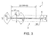
- FIG. 3 is a partial longitudinal sectional view showing the shape of the web of the drill shown in FIG. 1
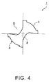
- FIG. 4 is an enlarged cross-sectional view of the drill shown in FIG. 1 .
- a drill 1 has a shank 2 and a body 3.
- the shank 2 is a portion of the drill 1 to be held by a holder of a machining apparatus, such as a handheld drill driving device or a machine tool.
- the body 3 is a portion to perform cutting processing of a workpiece.
- the body 3 has a structure in which cutting edges 5 are formed at the ends of the tip side of lands 4 whose number corresponds to the number of edges.
- the drill 1 shown in the figures is a two flute drill
- the cutting edge 5 has been formed at each end of the two lands 4.
- a flute 6 is formed between the adjacent lands 4.
- a ridgeline, formed at the tip of the drill 1, between the lands 4 is called a chisel edge 7.
- a desired number of the cutting edges 5 can be formed in the body 3. That is, a drill, having a desired number of edges, such as a four flute drill, can be manufactured. An angle formed between the two cutting edges 5 is called a point angle. A point angle is generally about from 118° to 120°.
- the platy portion passing through the central axis of the drill 1 is called a web 8.
- the board thickness of the web 8 is called a web thickness W.
- the drill 1 has a high strength.
- cutting resistance in the thrust direction increases when the chisel edge 7 becomes long.
- thinning which makes the web thickness W thin at the tip of the drill 1 can be performed in order to shorten the chisel edge 7.
- Types of thinning include R-shaped, X-shaped, N-shaped, and the like. In the example shown in the figures, X-shaped thinning has been applied.
- the drill 1 is for drilling at least one of a composite material and a metal. That is, the drill 1 is for drilling a workpiece made of a composite material, a workpiece made of a metal, or a workpiece made by layering a composite material with a metal. Therefore, it is practical to use a cemented carbide for at least the body 3.
- the whole drill 1 is usually made of a cemented carbide since the body 3 and the shank 2 are formed integrally by a method for sintering powder or the like.
- the body 3 may be made of a material having at least hardness and toughness similar to those of a cemented carbide.
- a cermet or a ceramic of which toughness has been improved to the same extent as that of a cemented carbide, having sufficient hardness can be used as a material of the body 3.
- a high-speed tool steel the hardness of which has been improved to the same extent as that of a cemented carbide, having sufficient toughness can also be used as a material of the body 3.
- a web thickness is designed to be at least 25 % of a drill diameter in order to secure sufficient strength to avoid chip of a cutting edge.
- the web thickness of drill is thick, cutting resistance in the thrust direction during drilling becomes large, as described above.
- a composite material such as CFRP
- the drill 1 shown in the figures is manufactured so that the web thickness W at least at the tip of the drill 1 becomes not less than 5 % and less than 25 % of a diameter D of the drill 1, which greatly differs from the conventional stereotype. Then, the length of the chisel edge 7 becomes still shorter, thereby a rake angle can be formed up to the vicinity of the tip of the drill 1.
- the most preferable web thickness W at the tip of the drill 1 was not less than 10 % and not more than 20 % of the diameter D of the drill 1, from a viewpoint of securing the strength of the drill 1 with reducing cutting resistance in the thrust direction of the drill 1. Therefore, it is preferable to manufacture the drill 1 so that the web thickness W at least at the tip of the drill 1 becomes not less than 10 % and not more than 20 % of the diameter D of the drill 1.
- a drill used for drilling an aircraft part has a diameter not less than the diameter of a drill whose nominal designation number is No. 11 (#11).
- the diameter of the #11 drill is 4.8514 mm (0.1910 inch).
- the diameter D of the drill 1 can be not less than the diameter of a drill whose nominal designation number is No. 11.
- the diameter D of the drill 1 may also be larger than 5 mm, from a viewpoint of keeping strength of the drill 1.
- the maximum of the diameter D of the drill 1 can be determined preferably according to design requirements of a workpiece, e.g., to 100 mm.
- the shape of the cutting edge 5 can be stepwise.
- the drill 1 is a two stage step drill having two diameters D1 and D2.
- the body 3 of the drill 1 has the first cutting edge 5A having the first diameter D1 and the first point angle ⁇ 1, and the second cutting edge 5B having the second diameter D2 and the second point angle ⁇ 2.
- a more than two stage step drill may also be manufactured.
- the torsion strength of the drill 1 can be dramatically improved by considerably tapering at least a part of the web 8. This is because strength of the web 8 is improved by thickening the web thickness W in the shank 2 side.
- the above-mentioned taper of the web 8, which is 5 to 10 times the conventional degree of taper, have efficacy from a viewpoint of improving strength of the drill 1, regardless of whether the drill 1 is a step drill.
- the web thicknesses W corresponding to respective diameters can be not less than 5 % and less than 25 % of the diameters respectively, by changing the web thickness W.
- the web thickness W in a portion of the web 8 in the shank 2 side of the drill 1 has tapered with a constant degree of taper Wt.
- the web thickness W of the drill 1 is gradually thickened with corresponding to the two diameters D1 and D2. That is, the web thickness W of the drill 1 intermittently changes corresponding to the two diameters D1 and D2. Consequently, strength of the drill 1 can be secured with reducing cutting resistance in the tip side of the drill 1.
- a drilled product can be manufactured by drilling a workpiece, made of at least one of a composite material and a metal, using the drill 1 having the features as described above.
- the drill 1 as described above is configured by dramatically thinning the web thickness W, giving the cutting edge 5 with a step or steps, and extremely tapering the web thickness W so as to enable securing strength with considerably reducing cutting resistance.
- the drill 1 can suppress generation of burrs and delamination in the case of drilling any of a workpiece made of a composite material, a workpiece made of a metal, and a workpiece made by layering a composite material and a metal.
- a workpiece can be drilled with satisfactory accuracy in the case of drilling any of a composite material, a metal, and a laminated material of a composite material and a metal.
- the drill 1 shown in the figures was actually manufactured under the following conditions.
- titanium was drilled by the manufactured drill 1.
- the drill 1 could drill the titanium with satisfactory accuracy with suppressing generation of burrs.
- the same drill 1 could drill CFRP with satisfactory accuracy with suppressing generation of burrs and delamination.
- FIG. 5 is a partial longitudinal sectional view showing the first modification of the shape of the web shown in FIG. 3 .
- FIG. 6 is a partial longitudinal sectional view showing the second modification of the shape of the web shown in FIG. 3 .
- the web 8 of the drill 1 can have not only the shape exemplified in FIG. 3 but also various shapes.
- the web 8 can be partially tapered by a length L3 so that the web thickness W changes smoothly from the first web thickness W1 to the second web thickness W2, and the web thicknesses W of the web 8 in the other portions can be constant or the web 8 in the other portions can be inclined to the same extent as that of the conventional drill. Thereby, stress concentration resulting from a local change of the web thickness W of the web 8 can be avoided.
- the web 8 can have a partial taper or tapers which have different inclined angles, corresponding to at least two diameters.
- the web thickness W in the tip side of the drill 1 can be made thin so that cutting resistance can be reduced while the web thickness W in the shank 2 side of the drill 1 can be secured so that strength of the drill 1 can be kept.
Landscapes
- Engineering & Computer Science (AREA)
- Mechanical Engineering (AREA)
- Drilling Tools (AREA)
Abstract
Description
- Embodiments described herein relate generally to a drill and a method of manufacturing a drilled product.
- Conventionally, aiming to drill a composite material or a metal with high precision, various drills have been proposed (for example, refer to Japanese Patent Application Publication
JP 2008-000 836 A JP 2014-037 008 A WO 2013/099841 A1 , and Japanese Patent Application PublicationJP H2-198 708 A - An object of the present invention is to provide a drill and a method of drilling which enable drilling of at least one of a metal and a composite material with higher precision.
- In general, according to one embodiment, a drill is provided that is adapted to drill at least one of a composite material and a metal is provided. A web thickness at least at a tip of the drill is not less than 5 % and less than 25 % of at least one diameter of the drill.
- Further, according to one embodiment, a method of manufacturing a drilled product is provided. The drilled product is manufactured by drilling a workpiece using the above-mentioned drill. The workpiece is made of the at least one of the composite material and the metal.
- In the accompanying drawings:
- FIG. 1
- is a front view of a drill according to an embodiment of the present invention;
- FIG. 2
- is an enlarged left side view of the drill shown in
FIG. 1 ; - FIG. 3
- is a partial longitudinal sectional view showing the shape of the web of the drill shown in
FIG. 1 ; - FIG. 4
- is an enlarged cross-sectional view of the drill shown in
FIG. 1 ; - FIG. 5
- is a partial longitudinal sectional view showing the first modification of the shape of the web shown in
FIG. 3 ; and - FIG. 6
- is a partial longitudinal sectional view showing the second modification of the shape of the web shown in
FIG. 3 . - A drill and a method of manufacturing a drilled product according to embodiments of the present invention will be described with reference to the accompanying drawings.
-
FIG. 1 is a front view of a drill according to an embodiment of the present invention,FIG. 2 is an enlarged left side view of the drill shown inFIG. 1 ,FIG. 3 is a partial longitudinal sectional view showing the shape of the web of the drill shown inFIG. 1 , andFIG. 4 is an enlarged cross-sectional view of the drill shown inFIG. 1 . - A
drill 1 has ashank 2 and abody 3. Theshank 2 is a portion of thedrill 1 to be held by a holder of a machining apparatus, such as a handheld drill driving device or a machine tool. Thebody 3 is a portion to perform cutting processing of a workpiece. Thebody 3 has a structure in which cuttingedges 5 are formed at the ends of the tip side oflands 4 whose number corresponds to the number of edges. - Since the
drill 1 shown in the figures is a two flute drill, thecutting edge 5 has been formed at each end of the twolands 4. Aflute 6 is formed between theadjacent lands 4. A ridgeline, formed at the tip of thedrill 1, between thelands 4 is called achisel edge 7. - As a matter of course, a desired number of the
cutting edges 5 can be formed in thebody 3. That is, a drill, having a desired number of edges, such as a four flute drill, can be manufactured. An angle formed between the twocutting edges 5 is called a point angle. A point angle is generally about from 118° to 120°. - The platy portion passing through the central axis of the
drill 1 is called aweb 8. The board thickness of theweb 8 is called a web thickness W. When the web thickness W is thick, thedrill 1 has a high strength. On the contrary, cutting resistance in the thrust direction increases when thechisel edge 7 becomes long. - Thus, thinning which makes the web thickness W thin at the tip of the
drill 1 can be performed in order to shorten thechisel edge 7. Types of thinning include R-shaped, X-shaped, N-shaped, and the like. In the example shown in the figures, X-shaped thinning has been applied. - The
drill 1 is for drilling at least one of a composite material and a metal. That is, thedrill 1 is for drilling a workpiece made of a composite material, a workpiece made of a metal, or a workpiece made by layering a composite material with a metal. Therefore, it is practical to use a cemented carbide for at least thebody 3. - That is, it is practical to use a cemented carbide drill as the
drill 1. In the case of a cemented carbide drill, thewhole drill 1 is usually made of a cemented carbide since thebody 3 and theshank 2 are formed integrally by a method for sintering powder or the like. - Alternatively, the
body 3 may be made of a material having at least hardness and toughness similar to those of a cemented carbide. For example, a cermet or a ceramic, of which toughness has been improved to the same extent as that of a cemented carbide, having sufficient hardness can be used as a material of thebody 3. Alternatively, a high-speed tool steel, the hardness of which has been improved to the same extent as that of a cemented carbide, having sufficient toughness can also be used as a material of thebody 3. - In the case of the conventional carbide drill for drilling at least one of a composite material and a metal, a web thickness is designed to be at least 25 % of a drill diameter in order to secure sufficient strength to avoid chip of a cutting edge. When the web thickness of drill is thick, cutting resistance in the thrust direction during drilling becomes large, as described above. As a result, when a composite material, such as CFRP, is drilled, there is a problem that delamination occurs at an inlet port of a hole.
- Thus, the
drill 1 shown in the figures is manufactured so that the web thickness W at least at the tip of thedrill 1 becomes not less than 5 % and less than 25 % of a diameter D of thedrill 1, which greatly differs from the conventional stereotype. Then, the length of thechisel edge 7 becomes still shorter, thereby a rake angle can be formed up to the vicinity of the tip of thedrill 1. - Therefore, cutting resistance in the thrust direction of the
drill 1 can be further reduced, and occurrence of delamination at the time of drilling of a composite material can be suppressed satisfactorily. Meanwhile, a strength of thedrill 1, necessary for drilling at least one of a composite material and a metal, can be secured. - In the case of drilling at least one of a composite material and a metal, it was confirmed that the most preferable web thickness W at the tip of the
drill 1 was not less than 10 % and not more than 20 % of the diameter D of thedrill 1, from a viewpoint of securing the strength of thedrill 1 with reducing cutting resistance in the thrust direction of thedrill 1. Therefore, it is preferable to manufacture thedrill 1 so that the web thickness W at least at the tip of thedrill 1 becomes not less than 10 % and not more than 20 % of the diameter D of thedrill 1. - A drill used for drilling an aircraft part has a diameter not less than the diameter of a drill whose nominal designation number is No. 11 (#11). The diameter of the #11 drill is 4.8514 mm (0.1910 inch).
- Therefore, the diameter D of the
drill 1 can be not less than the diameter of a drill whose nominal designation number is No. 11. The diameter D of thedrill 1 may also be larger than 5 mm, from a viewpoint of keeping strength of thedrill 1. The maximum of the diameter D of thedrill 1 can be determined preferably according to design requirements of a workpiece, e.g., to 100 mm. - When the web thickness W of the
drill 1 is made thin, it becomes important to compensate the strength of thedrill 1. Thus, it is preferable to use a step drill, having not less than two diameters, as thedrill 1. That is, the shape of thecutting edge 5 can be stepwise. - Thereby, it becomes possible to perform step processing which gradually widens the diameter of a hole of a workpiece. Consequently, cutting resistance in the thrust direction can be further reduced and the web thickness W of the
drill 1, necessary for securing strength, can be made thin. - In the example shown in the figures, the
drill 1 is a two stage step drill having two diameters D1 and D2. Specifically, thebody 3 of thedrill 1 has thefirst cutting edge 5A having the first diameter D1 and the first point angle α1, and thesecond cutting edge 5B having the second diameter D2 and the second point angle α2. As a matter of course, a more than two stage step drill may also be manufactured. - Furthermore, the torsion strength of the
drill 1 can be dramatically improved by considerably tapering at least a part of theweb 8. This is because strength of theweb 8 is improved by thickening the web thickness W in theshank 2 side. - When a degree of taper Wt of a web is expressed by an increased amount ΔW in thickness per unit length ΔL, the conventional drill may also have a web taper which is about Wt = ΔW/ΔL = 0.7/100 in general.
- By contrast, the degree of taper Wt = ΔW/ΔL of the
web 8 of thedrill 1 is determined to be not less than 3.5/100 and not more than 7.0/100. That is, at least a part of the web thickness W of thedrill 1 is manufactured to be thick not less than 3.5 mm and not more than 7.0 mm per 100 mm in the length direction. The above-mentioned taper of theweb 8, which is 5 to 10 times the conventional degree of taper, have efficacy from a viewpoint of improving strength of thedrill 1, regardless of whether thedrill 1 is a step drill. - When the
drill 1 is a step drill having at least two diameters, the web thicknesses W corresponding to respective diameters can be not less than 5 % and less than 25 % of the diameters respectively, by changing the web thickness W. In the example shown in the figures, the web thickness W in a portion, having a predetermined length of L0 in the tip side of thedrill 1, of theweb 8 is constant (Wt = 0). Meanwhile, the web thickness W in a portion of theweb 8 in theshank 2 side of thedrill 1 has tapered with a constant degree of taper Wt. - Therefore, the web thickness W of the
drill 1 is gradually thickened with corresponding to the two diameters D1 and D2. That is, the web thickness W of thedrill 1 intermittently changes corresponding to the two diameters D1 and D2. Consequently, strength of thedrill 1 can be secured with reducing cutting resistance in the tip side of thedrill 1. - In particular, in the case of drilling a composite material, generation of burrs besides delamination also poses a problem. Meanwhile, in the case of drilling a metal, it is also desirable to suppress generation of burrs. Thus, it is effective to form
nicks 9 on thelands 4 of thedrill 1. That is, generation of burrs and delamination can be suppressed by forming thenicks 9 in thedrill 1. - Then, a drilled product can be manufactured by drilling a workpiece, made of at least one of a composite material and a metal, using the
drill 1 having the features as described above. - The
drill 1 as described above is configured by dramatically thinning the web thickness W, giving thecutting edge 5 with a step or steps, and extremely tapering the web thickness W so as to enable securing strength with considerably reducing cutting resistance. - Accordingly, the
drill 1 can suppress generation of burrs and delamination in the case of drilling any of a workpiece made of a composite material, a workpiece made of a metal, and a workpiece made by layering a composite material and a metal. As a result, a workpiece can be drilled with satisfactory accuracy in the case of drilling any of a composite material, a metal, and a laminated material of a composite material and a metal. - The
drill 1 shown in the figures was actually manufactured under the following conditions. The first diameter was D1 = 6.35 mm; the second diameter was D2 = 7.9375 mm; a length of thebody 3 having the first diameter D1 was L1 = 6.5 mm; a length of thewhole body 3 having the first diameter D1 and the second diameter D2 was L2 = 63.43 mm; the first point angle was α1 = 120°; the second point angle was α2 = 120°; the web thickness at the tip of thedrill 1 was W = 0.79 mm; the length of theweb 8 whose web thickness W is constant (Wt = 0) was L0 = 40 mm; and the degree of taper of the web thickness W in theshank 2 side was Wt = 3.5/100. - Then, titanium was drilled by the manufactured
drill 1. In this case, it was confirmed that thedrill 1 could drill the titanium with satisfactory accuracy with suppressing generation of burrs. Furthermore, it was also confirmed that thesame drill 1 could drill CFRP with satisfactory accuracy with suppressing generation of burrs and delamination. -
FIG. 5 is a partial longitudinal sectional view showing the first modification of the shape of the web shown inFIG. 3 .FIG. 6 is a partial longitudinal sectional view showing the second modification of the shape of the web shown inFIG. 3 . - The
web 8 of thedrill 1 can have not only the shape exemplified inFIG. 3 but also various shapes. For example, in the case of a two stage step drill as shown inFIG. 5 , the first web thickness W1 at the tip of thedrill 1 can be R1 % of the first diameter D1 (W1 = D1·R1/100) while the second web thickness W2 at the start portion of the second diameter D2 can be R2 % of the second diameter D2 (W2 = D2·R2/100). - Then, the
web 8 in the portion having the first diameter D1 can be tapered with the first degree of taper Wt1 = (W2-W1)/L1 so that the thickness of theweb 8 changes from the first web thickness W1 to the second web thickness W2. Meanwhile, theweb 8 in the portion having the second diameter D2 can be tapered with the desired second degree of taper Wt2. - Alternatively, as shown in
FIG. 6 , the first web thickness W1 at the tip of thedrill 1 can be R1 % of the first diameter D1 (W1 = D1·R1/100) while the second web thickness W2 at the start portion of the second diameter D2 can be R2 % of the second diameter D2 (W2 = D2·R2/100). - Then, the
web 8 can be partially tapered by a length L3 so that the web thickness W changes smoothly from the first web thickness W1 to the second web thickness W2, and the web thicknesses W of theweb 8 in the other portions can be constant or theweb 8 in the other portions can be inclined to the same extent as that of the conventional drill. Thereby, stress concentration resulting from a local change of the web thickness W of theweb 8 can be avoided. - As described above, the
web 8 can have a partial taper or tapers which have different inclined angles, corresponding to at least two diameters. Thereby, the web thickness W in the tip side of thedrill 1 can be made thin so that cutting resistance can be reduced while the web thickness W in theshank 2 side of thedrill 1 can be secured so that strength of thedrill 1 can be kept. -
- 1
- drill
- 2
- shank
- 3
- body
- 4
- land
- 5
- cutting edge
- 5A
- cutting edge
- 5B
- cutting edge
- 6
- flute
- 7
- chisel edge
- 8
- web
- 9
- nick
- D
- diameter
- D1, D2
- diameter
- W
- web thickness
- W1, W2
- web thickness
- Wt
- taper
- α1, α2
- point angle
Claims (11)
- A drill (1) that drills at least one of a composite material and a metal,
wherein a web thickness at least at a tip of the drill (1) is not less than 5 % and less than 25 % of at least one diameter of the drill (1). - The drill (1) according to claim 1,
wherein a body (3) of the drill (1) is made of a cemented carbide or a material having at least a hardness and a toughness similar to a hardness and a toughness of the cemented carbide. - The drill (1) according to claim 1 or 2,
wherein the at least one diameter (D) is not less than a diameter of a drill (1) of which nominal designation number is 11. - The drill (1) according to claim 3,
wherein the at least one diameter (D) is larger than 5 mm. - The drill (1) according to any one of claims 1 to 4,
wherein the web thickness (W) at least at the tip of the drill (1) is not less than 10 % and not more than 20 % of the at least one diameter (D). - The drill (1) according to any one of claims 1 to 4,
wherein the drill (1) is a step drill having at least two diameters (D1, D2); and
wherein web thicknesses (W1, W2) corresponding to the at least two diameters (D1, D2) are not less than 5 % and less than 25 % of the at least two diameters (D1, D2) respectively. - The drill (1) according to any one of claims 1 to 6,
wherein at least a part of the web thickness (W) thickens not less than 3.5 mm per 100 mm in a length direction of the drill (1). - The drill (1) according to claim 6,
wherein a web (8) of the drill (1) has a partial taper or tapers having different inclined angles, the partial taper or the tapers corresponding to the at least two diameters (D1, D2). - The drill (1) according to any one of claims 1 to 8,
wherein at least one land (4) of the drill (1) has at least one nick (9). - A method of manufacturing a drilled product,
wherein the drilled product is manufactured by drilling a workpiece using a drill (1) according to any one of claims 1 to 9, the workpiece being made of at least one of a composite material and a metal. - Use of the drill according to any one of claims 1 to 9, for drilling a workpiece made of at least one of a composite material and a metal.
Applications Claiming Priority (1)
| Application Number | Priority Date | Filing Date | Title |
|---|---|---|---|
| JP2015170751A JP6747791B2 (en) | 2015-08-31 | 2015-08-31 | Method for manufacturing drill and perforated product |
Publications (2)
| Publication Number | Publication Date |
|---|---|
| EP3135414A1 true EP3135414A1 (en) | 2017-03-01 |
| EP3135414B1 EP3135414B1 (en) | 2020-05-20 |
Family
ID=56694050
Family Applications (1)
| Application Number | Title | Priority Date | Filing Date |
|---|---|---|---|
| EP16184468.3A Active EP3135414B1 (en) | 2015-08-31 | 2016-08-17 | Drill and method of manufacturing drilled product |
Country Status (4)
| Country | Link |
|---|---|
| US (1) | US9987691B2 (en) |
| EP (1) | EP3135414B1 (en) |
| JP (1) | JP6747791B2 (en) |
| CN (1) | CN106475607A (en) |
Cited By (3)
| Publication number | Priority date | Publication date | Assignee | Title |
|---|---|---|---|---|
| CN107363301A (en) * | 2017-08-01 | 2017-11-21 | 北京理工大学 | One kind becomes the thick change groove width small hole drilling cutters of core and its grinding method |
| EP3626372A1 (en) * | 2018-09-24 | 2020-03-25 | Lamina Technologies SA | Variable core diameter cutting tool and method for producing the same |
| CN111604514A (en) * | 2020-04-28 | 2020-09-01 | 昆明云内动力股份有限公司 | Method for machining shallow inclined hole of cylinder body |
Families Citing this family (14)
| Publication number | Priority date | Publication date | Assignee | Title |
|---|---|---|---|---|
| USD854062S1 (en) * | 2016-09-02 | 2019-07-16 | Robert Bosch Gmbh | Drill bit |
| JP1568741S (en) * | 2016-09-09 | 2017-02-06 | ||
| JP1581012S (en) * | 2016-11-17 | 2017-07-10 | ||
| USD840449S1 (en) * | 2017-06-28 | 2019-02-12 | Gino Development, Inc. | Twisted drill bit tip |
| JP6722153B2 (en) * | 2017-07-28 | 2020-07-15 | 株式会社Subaru | Drill, drilling unit and drilling method |
| USD878438S1 (en) * | 2018-08-06 | 2020-03-17 | Peter L. Bono | Helical fluted forward and reverse rotation cutting tool |
| USD878437S1 (en) * | 2018-08-06 | 2020-03-17 | Peter L. Bono | Helical fluted forward and reverse rotation cutting tool |
| CN109262738B (en) * | 2018-10-16 | 2020-01-24 | 大连理工大学 | A manual drill bit with a hook-back edge |
| USD881957S1 (en) * | 2019-06-27 | 2020-04-21 | Hongjia Wang | Twist drill |
| WO2021020259A1 (en) * | 2019-07-26 | 2021-02-04 | 京セラ株式会社 | Drill and method for manufacturing cut workpiece |
| US11260459B2 (en) * | 2020-04-30 | 2022-03-01 | The Boeing Company | Tools and methods for forming aligned holes from near full-sized holes |
| JP7545789B2 (en) | 2020-05-27 | 2024-09-05 | 株式会社Subaru | Hole finishing tool and method for manufacturing hole finishing product |
| JP2024043879A (en) * | 2022-09-20 | 2024-04-02 | イビデン株式会社 | Drill for glass fiber reinforced board |
| WO2025177407A1 (en) * | 2024-02-20 | 2025-08-28 | 住友電工ハードメタル株式会社 | Drill and machining method |
Citations (9)
| Publication number | Priority date | Publication date | Assignee | Title |
|---|---|---|---|---|
| DE1785012U (en) * | 1958-09-09 | 1959-03-12 | Spiralbohrer Und Werkzeugfabri | MULTIFILL STEP DRILL. |
| JPH02198708A (en) | 1988-10-31 | 1990-08-07 | G N Tool Kk | Cutting tool with nick |
| FR2656554A1 (en) * | 1989-12-28 | 1991-07-05 | Snecma | Precision drilling tool for composite materials |
| US5288183A (en) * | 1986-08-18 | 1994-02-22 | Black & Decker Inc. | Self-centering drill bit with pilot tip |
| DE29620308U1 (en) * | 1996-11-21 | 1997-04-03 | Hartmetallwerkzeugfabrik Andreas Maier GmbH, 88477 Schwendi | Micro drill |
| JP2008000836A (en) | 2006-06-21 | 2008-01-10 | Sumitomo Electric Hardmetal Corp | Drill |
| WO2013099841A1 (en) | 2011-12-27 | 2013-07-04 | 住友電気工業株式会社 | Drill |
| JP2014037008A (en) | 2012-08-10 | 2014-02-27 | Tochigi Prefecture | Boring drill |
| US20140356088A1 (en) * | 2013-03-15 | 2014-12-04 | Black & Decker Inc. | Drill bit |
Family Cites Families (17)
| Publication number | Priority date | Publication date | Assignee | Title |
|---|---|---|---|---|
| JPS5537284Y2 (en) * | 1972-06-09 | 1980-09-02 | ||
| JPS634211U (en) * | 1986-06-23 | 1988-01-12 | ||
| JPH02237711A (en) * | 1989-03-09 | 1990-09-20 | Mitsubishi Heavy Ind Ltd | Twist drill |
| JPH03149113A (en) * | 1989-11-07 | 1991-06-25 | Sumitomo Bakelite Co Ltd | Drilling to circuit board |
| JPH03184707A (en) * | 1989-12-15 | 1991-08-12 | Hitachi Ltd | twist drill |
| JPH04244311A (en) * | 1991-01-29 | 1992-09-01 | Hitachi Ltd | Three-stage web taper drill |
| JP2788148B2 (en) * | 1992-01-09 | 1998-08-20 | 三菱重工業株式会社 | Drill |
| JPH07164225A (en) * | 1993-12-15 | 1995-06-27 | Dijet Ind Co Ltd | Step drill |
| DE29722002U1 (en) * | 1997-12-15 | 1998-02-05 | Werkzeugfabrik GmbH Königsee, 07426 Königsee | Twist drill |
| JP2000015511A (en) * | 1998-06-30 | 2000-01-18 | Hitachi Tool Engineering Ltd | Twist drill |
| US6443674B1 (en) * | 2000-05-19 | 2002-09-03 | Ics Cutting Tools, Inc. | Self-centering twist drill having a modified flat bottom section and a helical crown point tip |
| JP2001322018A (en) * | 2000-05-19 | 2001-11-20 | Toshiba Tungaloy Co Ltd | Drill |
| JP2002126925A (en) * | 2000-10-25 | 2002-05-08 | Mmc Kobelco Tool Kk | Twist drill |
| JP2003039218A (en) * | 2001-07-24 | 2003-02-12 | Nachi Fujikoshi Corp | Drill for deep hole |
| US8740515B2 (en) * | 2008-09-03 | 2014-06-03 | Black & Decker Inc. | Metal cutting drill bit |
| JP6378493B2 (en) * | 2014-01-31 | 2018-08-22 | 旭ダイヤモンド工業株式会社 | drill |
| JP6343005B2 (en) * | 2014-07-29 | 2018-06-13 | 京セラ株式会社 | Drill and method of manufacturing cut product using the same |
-
2015
- 2015-08-31 JP JP2015170751A patent/JP6747791B2/en active Active
-
2016
- 2016-07-25 US US15/219,074 patent/US9987691B2/en active Active
- 2016-08-17 EP EP16184468.3A patent/EP3135414B1/en active Active
- 2016-08-25 CN CN201610727887.3A patent/CN106475607A/en active Pending
Patent Citations (9)
| Publication number | Priority date | Publication date | Assignee | Title |
|---|---|---|---|---|
| DE1785012U (en) * | 1958-09-09 | 1959-03-12 | Spiralbohrer Und Werkzeugfabri | MULTIFILL STEP DRILL. |
| US5288183A (en) * | 1986-08-18 | 1994-02-22 | Black & Decker Inc. | Self-centering drill bit with pilot tip |
| JPH02198708A (en) | 1988-10-31 | 1990-08-07 | G N Tool Kk | Cutting tool with nick |
| FR2656554A1 (en) * | 1989-12-28 | 1991-07-05 | Snecma | Precision drilling tool for composite materials |
| DE29620308U1 (en) * | 1996-11-21 | 1997-04-03 | Hartmetallwerkzeugfabrik Andreas Maier GmbH, 88477 Schwendi | Micro drill |
| JP2008000836A (en) | 2006-06-21 | 2008-01-10 | Sumitomo Electric Hardmetal Corp | Drill |
| WO2013099841A1 (en) | 2011-12-27 | 2013-07-04 | 住友電気工業株式会社 | Drill |
| JP2014037008A (en) | 2012-08-10 | 2014-02-27 | Tochigi Prefecture | Boring drill |
| US20140356088A1 (en) * | 2013-03-15 | 2014-12-04 | Black & Decker Inc. | Drill bit |
Cited By (4)
| Publication number | Priority date | Publication date | Assignee | Title |
|---|---|---|---|---|
| CN107363301A (en) * | 2017-08-01 | 2017-11-21 | 北京理工大学 | One kind becomes the thick change groove width small hole drilling cutters of core and its grinding method |
| EP3626372A1 (en) * | 2018-09-24 | 2020-03-25 | Lamina Technologies SA | Variable core diameter cutting tool and method for producing the same |
| WO2020064700A1 (en) * | 2018-09-24 | 2020-04-02 | Lamina Technologies Sa | Variable core diameter cutting tool and method for producing the same |
| CN111604514A (en) * | 2020-04-28 | 2020-09-01 | 昆明云内动力股份有限公司 | Method for machining shallow inclined hole of cylinder body |
Also Published As
| Publication number | Publication date |
|---|---|
| JP2017047486A (en) | 2017-03-09 |
| US20170056981A1 (en) | 2017-03-02 |
| CN106475607A (en) | 2017-03-08 |
| JP6747791B2 (en) | 2020-08-26 |
| EP3135414B1 (en) | 2020-05-20 |
| US9987691B2 (en) | 2018-06-05 |
Similar Documents
| Publication | Publication Date | Title |
|---|---|---|
| EP3135414B1 (en) | Drill and method of manufacturing drilled product | |
| US9409239B2 (en) | Drill bit | |
| US8602698B2 (en) | Combination end milling/drilling/reaming cutting tool | |
| JP5135614B2 (en) | Drill for composite material and machining method and machining apparatus using the same | |
| EP2818267B1 (en) | Twist drill for metal machining | |
| CN102649175B (en) | The segmented drill bit that goes in ring | |
| US20100158626A1 (en) | Drill and drilling method for workpiece | |
| US20130058734A1 (en) | Combined drill and reamer tool | |
| EP2698219A1 (en) | Drill | |
| EP2913131B1 (en) | Small-diameter drill | |
| JP6343005B2 (en) | Drill and method of manufacturing cut product using the same | |
| EP3195966A1 (en) | Drill | |
| KR101701023B1 (en) | Drilling tool | |
| WO2010086988A1 (en) | Double angle drill | |
| EP2758200B1 (en) | Drill reamer | |
| JP2008000836A (en) | Drill | |
| KR20200017378A (en) | drill | |
| EP3542937A1 (en) | Cutting tool and cutting method | |
| EP4159349A1 (en) | Drill bit for drilling a composite material | |
| CN117773198B (en) | Drilling section and hole-making tool for hole machining | |
| JP2008142834A (en) | Drill | |
| JP2648934B2 (en) | Small diameter drill for printed circuit board processing | |
| JP2002028810A (en) | Small drill | |
| HK1168325A (en) | Drill for composite material as well as machining method using same and machining apparatus using same |
Legal Events
| Date | Code | Title | Description |
|---|---|---|---|
| PUAI | Public reference made under article 153(3) epc to a published international application that has entered the european phase |
Free format text: ORIGINAL CODE: 0009012 |
|
| STAA | Information on the status of an ep patent application or granted ep patent |
Free format text: STATUS: THE APPLICATION HAS BEEN PUBLISHED |
|
| AK | Designated contracting states |
Kind code of ref document: A1 Designated state(s): AL AT BE BG CH CY CZ DE DK EE ES FI FR GB GR HR HU IE IS IT LI LT LU LV MC MK MT NL NO PL PT RO RS SE SI SK SM TR |
|
| AX | Request for extension of the european patent |
Extension state: BA ME |
|
| RAP1 | Party data changed (applicant data changed or rights of an application transferred) |
Owner name: MAKOTOLOY CO., LTD. Owner name: SUBARU CORPORATION Owner name: HONDA SEIMITSU KOGYO KABUSHIKI KAISHA |
|
| STAA | Information on the status of an ep patent application or granted ep patent |
Free format text: STATUS: REQUEST FOR EXAMINATION WAS MADE |
|
| 17P | Request for examination filed |
Effective date: 20170824 |
|
| RBV | Designated contracting states (corrected) |
Designated state(s): AL AT BE BG CH CY CZ DE DK EE ES FI FR GB GR HR HU IE IS IT LI LT LU LV MC MK MT NL NO PL PT RO RS SE SI SK SM TR |
|
| STAA | Information on the status of an ep patent application or granted ep patent |
Free format text: STATUS: EXAMINATION IS IN PROGRESS |
|
| 17Q | First examination report despatched |
Effective date: 20190319 |
|
| GRAP | Despatch of communication of intention to grant a patent |
Free format text: ORIGINAL CODE: EPIDOSNIGR1 |
|
| STAA | Information on the status of an ep patent application or granted ep patent |
Free format text: STATUS: GRANT OF PATENT IS INTENDED |
|
| INTG | Intention to grant announced |
Effective date: 20191209 |
|
| RAP1 | Party data changed (applicant data changed or rights of an application transferred) |
Owner name: SUBARU CORPORATION |
|
| GRAS | Grant fee paid |
Free format text: ORIGINAL CODE: EPIDOSNIGR3 |
|
| GRAA | (expected) grant |
Free format text: ORIGINAL CODE: 0009210 |
|
| STAA | Information on the status of an ep patent application or granted ep patent |
Free format text: STATUS: THE PATENT HAS BEEN GRANTED |
|
| AK | Designated contracting states |
Kind code of ref document: B1 Designated state(s): AL AT BE BG CH CY CZ DE DK EE ES FI FR GB GR HR HU IE IS IT LI LT LU LV MC MK MT NL NO PL PT RO RS SE SI SK SM TR |
|
| REG | Reference to a national code |
Ref country code: GB Ref legal event code: FG4D |
|
| RIN1 | Information on inventor provided before grant (corrected) |
Inventor name: HONDA, TAKUYA Inventor name: WATANABE, MASAO Inventor name: HIGASHIWAKI, HIROFUMI Inventor name: SAITO, MANABU |
|
| REG | Reference to a national code |
Ref country code: CH Ref legal event code: EP |
|
| REG | Reference to a national code |
Ref country code: DE Ref legal event code: R096 Ref document number: 602016036657 Country of ref document: DE |
|
| REG | Reference to a national code |
Ref country code: AT Ref legal event code: REF Ref document number: 1272286 Country of ref document: AT Kind code of ref document: T Effective date: 20200615 |
|
| REG | Reference to a national code |
Ref country code: LT Ref legal event code: MG4D |
|
| REG | Reference to a national code |
Ref country code: NL Ref legal event code: MP Effective date: 20200520 |
|
| PG25 | Lapsed in a contracting state [announced via postgrant information from national office to epo] |
Ref country code: LT Free format text: LAPSE BECAUSE OF FAILURE TO SUBMIT A TRANSLATION OF THE DESCRIPTION OR TO PAY THE FEE WITHIN THE PRESCRIBED TIME-LIMIT Effective date: 20200520 Ref country code: NO Free format text: LAPSE BECAUSE OF FAILURE TO SUBMIT A TRANSLATION OF THE DESCRIPTION OR TO PAY THE FEE WITHIN THE PRESCRIBED TIME-LIMIT Effective date: 20200820 Ref country code: GR Free format text: LAPSE BECAUSE OF FAILURE TO SUBMIT A TRANSLATION OF THE DESCRIPTION OR TO PAY THE FEE WITHIN THE PRESCRIBED TIME-LIMIT Effective date: 20200821 Ref country code: FI Free format text: LAPSE BECAUSE OF FAILURE TO SUBMIT A TRANSLATION OF THE DESCRIPTION OR TO PAY THE FEE WITHIN THE PRESCRIBED TIME-LIMIT Effective date: 20200520 Ref country code: SE Free format text: LAPSE BECAUSE OF FAILURE TO SUBMIT A TRANSLATION OF THE DESCRIPTION OR TO PAY THE FEE WITHIN THE PRESCRIBED TIME-LIMIT Effective date: 20200520 Ref country code: PT Free format text: LAPSE BECAUSE OF FAILURE TO SUBMIT A TRANSLATION OF THE DESCRIPTION OR TO PAY THE FEE WITHIN THE PRESCRIBED TIME-LIMIT Effective date: 20200921 Ref country code: IS Free format text: LAPSE BECAUSE OF FAILURE TO SUBMIT A TRANSLATION OF THE DESCRIPTION OR TO PAY THE FEE WITHIN THE PRESCRIBED TIME-LIMIT Effective date: 20200920 |
|
| PG25 | Lapsed in a contracting state [announced via postgrant information from national office to epo] |
Ref country code: LV Free format text: LAPSE BECAUSE OF FAILURE TO SUBMIT A TRANSLATION OF THE DESCRIPTION OR TO PAY THE FEE WITHIN THE PRESCRIBED TIME-LIMIT Effective date: 20200520 Ref country code: RS Free format text: LAPSE BECAUSE OF FAILURE TO SUBMIT A TRANSLATION OF THE DESCRIPTION OR TO PAY THE FEE WITHIN THE PRESCRIBED TIME-LIMIT Effective date: 20200520 Ref country code: HR Free format text: LAPSE BECAUSE OF FAILURE TO SUBMIT A TRANSLATION OF THE DESCRIPTION OR TO PAY THE FEE WITHIN THE PRESCRIBED TIME-LIMIT Effective date: 20200520 Ref country code: BG Free format text: LAPSE BECAUSE OF FAILURE TO SUBMIT A TRANSLATION OF THE DESCRIPTION OR TO PAY THE FEE WITHIN THE PRESCRIBED TIME-LIMIT Effective date: 20200820 |
|
| REG | Reference to a national code |
Ref country code: AT Ref legal event code: MK05 Ref document number: 1272286 Country of ref document: AT Kind code of ref document: T Effective date: 20200520 |
|
| PG25 | Lapsed in a contracting state [announced via postgrant information from national office to epo] |
Ref country code: NL Free format text: LAPSE BECAUSE OF FAILURE TO SUBMIT A TRANSLATION OF THE DESCRIPTION OR TO PAY THE FEE WITHIN THE PRESCRIBED TIME-LIMIT Effective date: 20200520 Ref country code: AL Free format text: LAPSE BECAUSE OF FAILURE TO SUBMIT A TRANSLATION OF THE DESCRIPTION OR TO PAY THE FEE WITHIN THE PRESCRIBED TIME-LIMIT Effective date: 20200520 |
|
| PG25 | Lapsed in a contracting state [announced via postgrant information from national office to epo] |
Ref country code: CZ Free format text: LAPSE BECAUSE OF FAILURE TO SUBMIT A TRANSLATION OF THE DESCRIPTION OR TO PAY THE FEE WITHIN THE PRESCRIBED TIME-LIMIT Effective date: 20200520 Ref country code: AT Free format text: LAPSE BECAUSE OF FAILURE TO SUBMIT A TRANSLATION OF THE DESCRIPTION OR TO PAY THE FEE WITHIN THE PRESCRIBED TIME-LIMIT Effective date: 20200520 Ref country code: EE Free format text: LAPSE BECAUSE OF FAILURE TO SUBMIT A TRANSLATION OF THE DESCRIPTION OR TO PAY THE FEE WITHIN THE PRESCRIBED TIME-LIMIT Effective date: 20200520 Ref country code: SM Free format text: LAPSE BECAUSE OF FAILURE TO SUBMIT A TRANSLATION OF THE DESCRIPTION OR TO PAY THE FEE WITHIN THE PRESCRIBED TIME-LIMIT Effective date: 20200520 Ref country code: DK Free format text: LAPSE BECAUSE OF FAILURE TO SUBMIT A TRANSLATION OF THE DESCRIPTION OR TO PAY THE FEE WITHIN THE PRESCRIBED TIME-LIMIT Effective date: 20200520 Ref country code: ES Free format text: LAPSE BECAUSE OF FAILURE TO SUBMIT A TRANSLATION OF THE DESCRIPTION OR TO PAY THE FEE WITHIN THE PRESCRIBED TIME-LIMIT Effective date: 20200520 Ref country code: RO Free format text: LAPSE BECAUSE OF FAILURE TO SUBMIT A TRANSLATION OF THE DESCRIPTION OR TO PAY THE FEE WITHIN THE PRESCRIBED TIME-LIMIT Effective date: 20200520 |
|
| REG | Reference to a national code |
Ref country code: DE Ref legal event code: R097 Ref document number: 602016036657 Country of ref document: DE |
|
| PG25 | Lapsed in a contracting state [announced via postgrant information from national office to epo] |
Ref country code: SK Free format text: LAPSE BECAUSE OF FAILURE TO SUBMIT A TRANSLATION OF THE DESCRIPTION OR TO PAY THE FEE WITHIN THE PRESCRIBED TIME-LIMIT Effective date: 20200520 Ref country code: PL Free format text: LAPSE BECAUSE OF FAILURE TO SUBMIT A TRANSLATION OF THE DESCRIPTION OR TO PAY THE FEE WITHIN THE PRESCRIBED TIME-LIMIT Effective date: 20200520 |
|
| PLBE | No opposition filed within time limit |
Free format text: ORIGINAL CODE: 0009261 |
|
| STAA | Information on the status of an ep patent application or granted ep patent |
Free format text: STATUS: NO OPPOSITION FILED WITHIN TIME LIMIT |
|
| PG25 | Lapsed in a contracting state [announced via postgrant information from national office to epo] |
Ref country code: MC Free format text: LAPSE BECAUSE OF FAILURE TO SUBMIT A TRANSLATION OF THE DESCRIPTION OR TO PAY THE FEE WITHIN THE PRESCRIBED TIME-LIMIT Effective date: 20200520 |
|
| REG | Reference to a national code |
Ref country code: CH Ref legal event code: PL |
|
| 26N | No opposition filed |
Effective date: 20210223 |
|
| GBPC | Gb: european patent ceased through non-payment of renewal fee |
Effective date: 20200820 |
|
| PG25 | Lapsed in a contracting state [announced via postgrant information from national office to epo] |
Ref country code: CH Free format text: LAPSE BECAUSE OF NON-PAYMENT OF DUE FEES Effective date: 20200831 Ref country code: LU Free format text: LAPSE BECAUSE OF NON-PAYMENT OF DUE FEES Effective date: 20200817 Ref country code: LI Free format text: LAPSE BECAUSE OF NON-PAYMENT OF DUE FEES Effective date: 20200831 |
|
| REG | Reference to a national code |
Ref country code: BE Ref legal event code: MM Effective date: 20200831 |
|
| PG25 | Lapsed in a contracting state [announced via postgrant information from national office to epo] |
Ref country code: SI Free format text: LAPSE BECAUSE OF FAILURE TO SUBMIT A TRANSLATION OF THE DESCRIPTION OR TO PAY THE FEE WITHIN THE PRESCRIBED TIME-LIMIT Effective date: 20200520 |
|
| PG25 | Lapsed in a contracting state [announced via postgrant information from national office to epo] |
Ref country code: GB Free format text: LAPSE BECAUSE OF NON-PAYMENT OF DUE FEES Effective date: 20200820 Ref country code: IE Free format text: LAPSE BECAUSE OF NON-PAYMENT OF DUE FEES Effective date: 20200817 Ref country code: BE Free format text: LAPSE BECAUSE OF NON-PAYMENT OF DUE FEES Effective date: 20200831 |
|
| PG25 | Lapsed in a contracting state [announced via postgrant information from national office to epo] |
Ref country code: TR Free format text: LAPSE BECAUSE OF FAILURE TO SUBMIT A TRANSLATION OF THE DESCRIPTION OR TO PAY THE FEE WITHIN THE PRESCRIBED TIME-LIMIT Effective date: 20200520 Ref country code: MT Free format text: LAPSE BECAUSE OF FAILURE TO SUBMIT A TRANSLATION OF THE DESCRIPTION OR TO PAY THE FEE WITHIN THE PRESCRIBED TIME-LIMIT Effective date: 20200520 Ref country code: CY Free format text: LAPSE BECAUSE OF FAILURE TO SUBMIT A TRANSLATION OF THE DESCRIPTION OR TO PAY THE FEE WITHIN THE PRESCRIBED TIME-LIMIT Effective date: 20200520 |
|
| PG25 | Lapsed in a contracting state [announced via postgrant information from national office to epo] |
Ref country code: MK Free format text: LAPSE BECAUSE OF FAILURE TO SUBMIT A TRANSLATION OF THE DESCRIPTION OR TO PAY THE FEE WITHIN THE PRESCRIBED TIME-LIMIT Effective date: 20200520 |
|
| PGFP | Annual fee paid to national office [announced via postgrant information from national office to epo] |
Ref country code: DE Payment date: 20250820 Year of fee payment: 10 |
|
| PGFP | Annual fee paid to national office [announced via postgrant information from national office to epo] |
Ref country code: IT Payment date: 20250825 Year of fee payment: 10 |
|
| PGFP | Annual fee paid to national office [announced via postgrant information from national office to epo] |
Ref country code: FR Payment date: 20250829 Year of fee payment: 10 |