EP3135216B1 - Surgical stapler buttress applicator with multi-point actuated release mechanism - Google Patents
Surgical stapler buttress applicator with multi-point actuated release mechanism Download PDFInfo
- Publication number
- EP3135216B1 EP3135216B1 EP16185387.4A EP16185387A EP3135216B1 EP 3135216 B1 EP3135216 B1 EP 3135216B1 EP 16185387 A EP16185387 A EP 16185387A EP 3135216 B1 EP3135216 B1 EP 3135216B1
- Authority
- EP
- European Patent Office
- Prior art keywords
- end effector
- buttress
- platform
- buttress assembly
- latch
- Prior art date
- Legal status (The legal status is an assumption and is not a legal conclusion. Google has not performed a legal analysis and makes no representation as to the accuracy of the status listed.)
- Active
Links
- 230000007246 mechanism Effects 0.000 title description 9
- 239000012636 effector Substances 0.000 claims description 142
- 238000000034 method Methods 0.000 claims description 34
- 230000007704 transition Effects 0.000 claims description 10
- 230000004044 response Effects 0.000 claims description 7
- 230000009471 action Effects 0.000 claims description 2
- 230000000295 complement effect Effects 0.000 claims 2
- 230000000712 assembly Effects 0.000 description 70
- 238000000429 assembly Methods 0.000 description 70
- 239000000463 material Substances 0.000 description 49
- 239000010410 layer Substances 0.000 description 20
- 239000012790 adhesive layer Substances 0.000 description 13
- 238000010304 firing Methods 0.000 description 13
- 239000011324 bead Substances 0.000 description 12
- 238000001356 surgical procedure Methods 0.000 description 12
- 239000000853 adhesive Substances 0.000 description 8
- 230000001070 adhesive effect Effects 0.000 description 8
- 230000014759 maintenance of location Effects 0.000 description 7
- 238000013519 translation Methods 0.000 description 7
- 230000033001 locomotion Effects 0.000 description 6
- 239000002274 desiccant Substances 0.000 description 5
- 239000003814 drug Substances 0.000 description 5
- 239000012530 fluid Substances 0.000 description 4
- 239000002874 hemostatic agent Substances 0.000 description 4
- 230000005855 radiation Effects 0.000 description 4
- 230000000007 visual effect Effects 0.000 description 4
- 229920000954 Polyglycolide Polymers 0.000 description 3
- 229940030225 antihemorrhagics Drugs 0.000 description 3
- 238000004140 cleaning Methods 0.000 description 3
- 229940079593 drug Drugs 0.000 description 3
- 230000014509 gene expression Effects 0.000 description 3
- 238000009434 installation Methods 0.000 description 3
- 239000011159 matrix material Substances 0.000 description 3
- 238000012986 modification Methods 0.000 description 3
- 230000004048 modification Effects 0.000 description 3
- 210000000056 organ Anatomy 0.000 description 3
- 230000002787 reinforcement Effects 0.000 description 3
- 238000007789 sealing Methods 0.000 description 3
- 102000009123 Fibrin Human genes 0.000 description 2
- 108010073385 Fibrin Proteins 0.000 description 2
- BWGVNKXGVNDBDI-UHFFFAOYSA-N Fibrin monomer Chemical compound CNC(=O)CNC(=O)CN BWGVNKXGVNDBDI-UHFFFAOYSA-N 0.000 description 2
- 239000004820 Pressure-sensitive adhesive Substances 0.000 description 2
- 230000002411 adverse Effects 0.000 description 2
- 230000005540 biological transmission Effects 0.000 description 2
- 230000000740 bleeding effect Effects 0.000 description 2
- 239000008280 blood Substances 0.000 description 2
- 210000004369 blood Anatomy 0.000 description 2
- 239000013536 elastomeric material Substances 0.000 description 2
- 239000000835 fiber Substances 0.000 description 2
- 229950003499 fibrin Drugs 0.000 description 2
- 239000006261 foam material Substances 0.000 description 2
- 238000003780 insertion Methods 0.000 description 2
- 230000037431 insertion Effects 0.000 description 2
- 239000000203 mixture Substances 0.000 description 2
- 230000002035 prolonged effect Effects 0.000 description 2
- 230000035945 sensitivity Effects 0.000 description 2
- 125000006850 spacer group Chemical group 0.000 description 2
- 230000001954 sterilising effect Effects 0.000 description 2
- 238000004659 sterilization and disinfection Methods 0.000 description 2
- 210000000115 thoracic cavity Anatomy 0.000 description 2
- 238000011282 treatment Methods 0.000 description 2
- 241000894006 Bacteria Species 0.000 description 1
- 102000008186 Collagen Human genes 0.000 description 1
- 108010035532 Collagen Proteins 0.000 description 1
- IAYPIBMASNFSPL-UHFFFAOYSA-N Ethylene oxide Chemical compound C1CO1 IAYPIBMASNFSPL-UHFFFAOYSA-N 0.000 description 1
- 229920005830 Polyurethane Foam Polymers 0.000 description 1
- VYPSYNLAJGMNEJ-UHFFFAOYSA-N Silicium dioxide Chemical compound O=[Si]=O VYPSYNLAJGMNEJ-UHFFFAOYSA-N 0.000 description 1
- 108090000190 Thrombin Proteins 0.000 description 1
- 239000004775 Tyvek Substances 0.000 description 1
- 229920000690 Tyvek Polymers 0.000 description 1
- 210000001015 abdomen Anatomy 0.000 description 1
- 230000006978 adaptation Effects 0.000 description 1
- 230000003872 anastomosis Effects 0.000 description 1
- 230000009286 beneficial effect Effects 0.000 description 1
- 230000015572 biosynthetic process Effects 0.000 description 1
- 210000001124 body fluid Anatomy 0.000 description 1
- 230000008859 change Effects 0.000 description 1
- 239000003153 chemical reaction reagent Substances 0.000 description 1
- 230000001112 coagulating effect Effects 0.000 description 1
- 229920001436 collagen Polymers 0.000 description 1
- 238000013270 controlled release Methods 0.000 description 1
- 230000008878 coupling Effects 0.000 description 1
- 238000010168 coupling process Methods 0.000 description 1
- 238000005859 coupling reaction Methods 0.000 description 1
- 238000002651 drug therapy Methods 0.000 description 1
- 230000000694 effects Effects 0.000 description 1
- 229920001971 elastomer Polymers 0.000 description 1
- 230000007613 environmental effect Effects 0.000 description 1
- 239000002657 fibrous material Substances 0.000 description 1
- 238000001415 gene therapy Methods 0.000 description 1
- 230000002439 hemostatic effect Effects 0.000 description 1
- 238000002955 isolation Methods 0.000 description 1
- 210000004072 lung Anatomy 0.000 description 1
- 238000002324 minimally invasive surgery Methods 0.000 description 1
- 230000001151 other effect Effects 0.000 description 1
- 229920003023 plastic Polymers 0.000 description 1
- 239000004033 plastic Substances 0.000 description 1
- 239000004633 polyglycolic acid Substances 0.000 description 1
- 239000011496 polyurethane foam Substances 0.000 description 1
- 230000002980 postoperative effect Effects 0.000 description 1
- 230000002265 prevention Effects 0.000 description 1
- 238000012545 processing Methods 0.000 description 1
- 238000011084 recovery Methods 0.000 description 1
- 230000003014 reinforcing effect Effects 0.000 description 1
- 230000000717 retained effect Effects 0.000 description 1
- 229920003031 santoprene Polymers 0.000 description 1
- 239000000565 sealant Substances 0.000 description 1
- 239000000741 silica gel Substances 0.000 description 1
- 229910002027 silica gel Inorganic materials 0.000 description 1
- 238000004381 surface treatment Methods 0.000 description 1
- 229940124597 therapeutic agent Drugs 0.000 description 1
- 230000001225 therapeutic effect Effects 0.000 description 1
- 238000002560 therapeutic procedure Methods 0.000 description 1
- 229960004072 thrombin Drugs 0.000 description 1
- YFHICDDUDORKJB-UHFFFAOYSA-N trimethylene carbonate Chemical compound O=C1OCCCO1 YFHICDDUDORKJB-UHFFFAOYSA-N 0.000 description 1
- 238000002604 ultrasonography Methods 0.000 description 1
- 210000001835 viscera Anatomy 0.000 description 1
- 210000000707 wrist Anatomy 0.000 description 1
Images


Classifications
-
- A—HUMAN NECESSITIES
- A61—MEDICAL OR VETERINARY SCIENCE; HYGIENE
- A61B—DIAGNOSIS; SURGERY; IDENTIFICATION
- A61B17/00—Surgical instruments, devices or methods, e.g. tourniquets
- A61B17/068—Surgical staplers, e.g. containing multiple staples or clamps
- A61B17/072—Surgical staplers, e.g. containing multiple staples or clamps for applying a row of staples in a single action, e.g. the staples being applied simultaneously
- A61B17/07292—Reinforcements for staple line, e.g. pledgets
-
- A—HUMAN NECESSITIES
- A61—MEDICAL OR VETERINARY SCIENCE; HYGIENE
- A61B—DIAGNOSIS; SURGERY; IDENTIFICATION
- A61B17/00—Surgical instruments, devices or methods, e.g. tourniquets
- A61B17/068—Surgical staplers, e.g. containing multiple staples or clamps
- A61B17/0682—Surgical staplers, e.g. containing multiple staples or clamps for applying U-shaped staples or clamps, e.g. without a forming anvil
-
- A—HUMAN NECESSITIES
- A61—MEDICAL OR VETERINARY SCIENCE; HYGIENE
- A61B—DIAGNOSIS; SURGERY; IDENTIFICATION
- A61B17/00—Surgical instruments, devices or methods, e.g. tourniquets
- A61B17/10—Surgical instruments, devices or methods, e.g. tourniquets for applying or removing wound clamps, e.g. containing only one clamp or staple; Wound clamp magazines
- A61B17/105—Wound clamp magazines
-
- A—HUMAN NECESSITIES
- A61—MEDICAL OR VETERINARY SCIENCE; HYGIENE
- A61B—DIAGNOSIS; SURGERY; IDENTIFICATION
- A61B17/00—Surgical instruments, devices or methods, e.g. tourniquets
- A61B17/068—Surgical staplers, e.g. containing multiple staples or clamps
- A61B17/072—Surgical staplers, e.g. containing multiple staples or clamps for applying a row of staples in a single action, e.g. the staples being applied simultaneously
- A61B17/07207—Surgical staplers, e.g. containing multiple staples or clamps for applying a row of staples in a single action, e.g. the staples being applied simultaneously the staples being applied sequentially
-
- A—HUMAN NECESSITIES
- A61—MEDICAL OR VETERINARY SCIENCE; HYGIENE
- A61B—DIAGNOSIS; SURGERY; IDENTIFICATION
- A61B17/00—Surgical instruments, devices or methods, e.g. tourniquets
- A61B2017/00017—Electrical control of surgical instruments
- A61B2017/00115—Electrical control of surgical instruments with audible or visual output
-
- A—HUMAN NECESSITIES
- A61—MEDICAL OR VETERINARY SCIENCE; HYGIENE
- A61B—DIAGNOSIS; SURGERY; IDENTIFICATION
- A61B17/00—Surgical instruments, devices or methods, e.g. tourniquets
- A61B2017/00477—Coupling
-
- A—HUMAN NECESSITIES
- A61—MEDICAL OR VETERINARY SCIENCE; HYGIENE
- A61B—DIAGNOSIS; SURGERY; IDENTIFICATION
- A61B17/00—Surgical instruments, devices or methods, e.g. tourniquets
- A61B2017/00526—Methods of manufacturing
- A61B2017/0053—Loading magazines or sutures into applying tools
-
- A—HUMAN NECESSITIES
- A61—MEDICAL OR VETERINARY SCIENCE; HYGIENE
- A61B—DIAGNOSIS; SURGERY; IDENTIFICATION
- A61B17/00—Surgical instruments, devices or methods, e.g. tourniquets
- A61B2017/00831—Material properties
- A61B2017/00951—Material properties adhesive
-
- A—HUMAN NECESSITIES
- A61—MEDICAL OR VETERINARY SCIENCE; HYGIENE
- A61B—DIAGNOSIS; SURGERY; IDENTIFICATION
- A61B17/00—Surgical instruments, devices or methods, e.g. tourniquets
- A61B17/068—Surgical staplers, e.g. containing multiple staples or clamps
- A61B17/072—Surgical staplers, e.g. containing multiple staples or clamps for applying a row of staples in a single action, e.g. the staples being applied simultaneously
- A61B2017/07214—Stapler heads
- A61B2017/07257—Stapler heads characterised by its anvil
-
- A—HUMAN NECESSITIES
- A61—MEDICAL OR VETERINARY SCIENCE; HYGIENE
- A61B—DIAGNOSIS; SURGERY; IDENTIFICATION
- A61B17/00—Surgical instruments, devices or methods, e.g. tourniquets
- A61B17/068—Surgical staplers, e.g. containing multiple staples or clamps
- A61B17/072—Surgical staplers, e.g. containing multiple staples or clamps for applying a row of staples in a single action, e.g. the staples being applied simultaneously
- A61B2017/07214—Stapler heads
- A61B2017/07271—Stapler heads characterised by its cartridge
-
- A—HUMAN NECESSITIES
- A61—MEDICAL OR VETERINARY SCIENCE; HYGIENE
- A61B—DIAGNOSIS; SURGERY; IDENTIFICATION
- A61B50/00—Containers, covers, furniture or holders specially adapted for surgical or diagnostic appliances or instruments, e.g. sterile covers
- A61B2050/005—Containers, covers, furniture or holders specially adapted for surgical or diagnostic appliances or instruments, e.g. sterile covers with a lid or cover
- A61B2050/0058—Containers, covers, furniture or holders specially adapted for surgical or diagnostic appliances or instruments, e.g. sterile covers with a lid or cover closable by translation
-
- A—HUMAN NECESSITIES
- A61—MEDICAL OR VETERINARY SCIENCE; HYGIENE
- A61B—DIAGNOSIS; SURGERY; IDENTIFICATION
- A61B90/00—Instruments, implements or accessories specially adapted for surgery or diagnosis and not covered by any of the groups A61B1/00 - A61B50/00, e.g. for luxation treatment or for protecting wound edges
- A61B90/08—Accessories or related features not otherwise provided for
- A61B2090/0807—Indication means
- A61B2090/081—Indication means for contamination or dirt
-
- A—HUMAN NECESSITIES
- A61—MEDICAL OR VETERINARY SCIENCE; HYGIENE
- A61B—DIAGNOSIS; SURGERY; IDENTIFICATION
- A61B90/00—Instruments, implements or accessories specially adapted for surgery or diagnosis and not covered by any of the groups A61B1/00 - A61B50/00, e.g. for luxation treatment or for protecting wound edges
- A61B90/08—Accessories or related features not otherwise provided for
- A61B2090/0807—Indication means
- A61B2090/0811—Indication means for the position of a particular part of an instrument with respect to the rest of the instrument, e.g. position of the anvil of a stapling instrument
-
- A—HUMAN NECESSITIES
- A61—MEDICAL OR VETERINARY SCIENCE; HYGIENE
- A61B—DIAGNOSIS; SURGERY; IDENTIFICATION
- A61B2562/00—Details of sensors; Constructional details of sensor housings or probes; Accessories for sensors
- A61B2562/02—Details of sensors specially adapted for in-vivo measurements
- A61B2562/029—Humidity sensors
-
- A—HUMAN NECESSITIES
- A61—MEDICAL OR VETERINARY SCIENCE; HYGIENE
- A61B—DIAGNOSIS; SURGERY; IDENTIFICATION
- A61B5/00—Measuring for diagnostic purposes; Identification of persons
- A61B5/68—Arrangements of detecting, measuring or recording means, e.g. sensors, in relation to patient
- A61B5/6846—Arrangements of detecting, measuring or recording means, e.g. sensors, in relation to patient specially adapted to be brought in contact with an internal body part, i.e. invasive
- A61B5/6847—Arrangements of detecting, measuring or recording means, e.g. sensors, in relation to patient specially adapted to be brought in contact with an internal body part, i.e. invasive mounted on an invasive device
-
- A—HUMAN NECESSITIES
- A61—MEDICAL OR VETERINARY SCIENCE; HYGIENE
- A61B—DIAGNOSIS; SURGERY; IDENTIFICATION
- A61B50/00—Containers, covers, furniture or holders specially adapted for surgical or diagnostic appliances or instruments, e.g. sterile covers
Description
- In some settings, endoscopic surgical instruments may be preferred over traditional open surgical devices since a smaller incision may reduce the post-operative recovery time and complications. Consequently, some endoscopic surgical instruments may be suitable for placement of a distal end effector at a desired surgical site through the cannula of a trocar. These distal end effectors may engage tissue in a number of ways to achieve a diagnostic or therapeutic effect (e.g., endocutter, grasper, cutter, stapler, clip applier, access device, drug/ gene therapy delivery device, and energy delivery device using ultrasonic vibration, RF, laser, etc.). Endoscopic surgical instruments may include a shaft between the end effector and a handle portion, which is manipulated by the clinician. Such a shaft may enable insertion to a desired depth and rotation about the longitudinal axis of the shaft, thereby facilitating positioning of the end effector within the patient. Positioning of an end effector may be further facilitated through inclusion of one or more articulation joints or features, enabling the end effector to be selectively articulated or otherwise deflected relative to the longitudinal axis of the shaft.
- Examples of endoscopic surgical instruments include surgical staplers. Some such staplers are operable to clamp down on layers of tissue, cut through the clamped
layers of tissue, and drive staples through the layers of tissue to substantially seal the severed layers of tissue together near the severed ends of the tissue layers. Merely exemplary surgical staplers are disclosed inU.S. Pat. No. 4,805,823 , entitled "Pocket Configuration for Internal Organ Staplers," issued February 21, 1989;U.S. Pat. No. 5,415,334 , entitled "Surgical Stapler and Staple Cartridge," issued May 16, 1995;U.S. Pat. No. 5,465,895 , entitled "Surgical Stapler Instrument," issued November 14, 1995;U.S. Pat. No. 5,597,107 , entitled "Surgical Stapler Instrument," issued January 28, 1997;U.S. Pat. No. 5,632,432 , entitled "Surgical Instrument," issued May 27, 1997;U.S. Pat. No. 5,673,840 , entitled "Surgical Instrument," issued October 7, 1997;U.S. Pat. No. 5,704,534 , entitled "Articulation Assembly for Surgical Instruments," issued January 6, 1998;U.S. Pat. No. 5,814,055 , entitled "Surgical Clamping Mechanism," issued September 29, 1998;U.S. Pat. No. 6,978,921 , entitled "Surgical Stapling Instrument Incorporating an E-Beam Firing Mechanism," issued December 27, 2005;U.S. Pat. No. 7,000,818 , entitled "Surgical Stapling Instrument Having Separate Distinct Closing and Firing Systems," issued February 21, 2006;U.S. Pat. No. 7,143,923 , entitled "Surgical Stapling Instrument Having a Firing Lockout for an Unclosed Anvil," issued December 5, 2006;U.S. Pat. No. 7,303,108 , entitled "Surgical Stapling Instrument Incorporating a Multi-Stroke Firing Mechanism with a Flexible Rack," issued December 4, 2007;U.S. Pat. No. 7,367,485 , entitled "Surgical Stapling Instrument Incorporating a Multistroke Firing Mechanism Having a Rotary Transmission," issued May 6, 2008;U.S. Pat. No. 7,380,695 , entitled "Surgical Stapling Instrument Having a Single Lockout Mechanism for Prevention of Firing," issued June 3, 2008;U.S. Pat. No. 7,380,696 , entitled "Articulating Surgical Stapling Instrument Incorporating a Two-Piece E-Beam Firing Mechanism," issued June 3, 2008;U.S. Pat. No. 7,404,508 , entitled "Surgical Stapling and Cutting Device," issued July 29, 2008;U.S. Pat. No. 7,434,715 , entitled "Surgical Stapling Instrument Having Multistroke Firing with Opening Lockout," issued October 14, 2008;U.S. Pat. No. 7,721,930 , entitled "Disposable Cartridge with Adhesive for Use with a Stapling Device," issued May 25, 2010;U.S. Pat. No. 8,408,439 , entitled "Surgical Stapling Instrument with An Articulatable End Effector," issued April 2, 2013; andU.S. Pat. No. 8,453,914 , entitled "Motor-Driven Surgical Cutting Instrument with Electric Actuator Directional Control Assembly," issued June 4, 2013. - While the surgical staplers referred to above are described as being used in endoscopic procedures, it should be understood that such surgical staplers may also be used in open procedures and/or other non-endoscopic procedures. By way of example only, a surgical stapler may be inserted through a thoracotomy, and thereby between a patient's ribs, to reach one or more organs in a thoracic surgical procedure that does not use a trocar as a conduit for the stapler. Such procedures may include the use of the stapler to sever and close a vessel leading to a lung. For instance, the vessels leading to an organ may be severed and closed by a stapler before removal of the organ from the thoracic cavity. Of course, surgical staplers may be used in various other settings and procedures.
- Examples of surgical staplers that may be particularly suited for use through a thoracotomy are disclosed in
U.S. Patent Pub. No. 2014/0243801 , entitled "Surgical Instrument End Effector Articulation Drive with Pinion and Opposing Racks," published August 28, 2014;U.S. Patent Pub. No. 2014/0239041 , entitled "Lockout Feature for Movable Cutting Member of Surgical Instrument," published August 28, 2014;U.S. Patent Pub. No. 2014/0239042 , entitled "Integrated Tissue Positioning and Jaw Alignment Features for Surgical Stapler," published August 28, 2014;U.S. Patent Pub. No. 2014/0239036 , entitled "Jaw Closure Feature for End Effector of Surgical Instrument," published August 28, 2014;U.S. Patent Pub. No. 2014/0239040 , entitled "Surgical Instrument with Articulation Lock having a Detenting Binary Spring," published August 28, 2014;U.S. Patent Pub. No. 2014/0239043 , entitled "Distal Tip Features for End Effector of Surgical Instrument," published August 28, 2014;U.S. Patent Pub. No. 2014/0239037 , entitled "Staple Forming Features for Surgical Stapling Instrument," published August 28, 2014;U.S. Patent Pub. No. 2014/0239038 , entitled "Surgical Instrument with Multi-Diameter Shaft," published August 28, 2014; andU.S. Patent Pub. No. 2014/0239044 , entitled "Installation Features for Surgical Instrument End Effector Cartridge," published August 28, 2014. - Additional surgical stapling instruments are disclosed in
U.S. Pat. No. 8,801,735 , entitled "Surgical Circular Stapler with Tissue Retention Arrangements," issued August 12, 2014;U.S. Pat. No. 8,141,762 , entitled "Surgical Stapler Comprising a Staple Pocket," issued March 27, 2012;U.S. Pat. No. 8,371,491 , entitled "Surgical End Effector Having Buttress Retention Features," issued February 12, 2013;U.S. Pub. No. 2014/0263563 , entitled "Method and Apparatus for Sealing End-to-End Anastomosis" published September 18, 2014;U.S. Pub. No. 2014/0246473 , entitled "Rotary Powered Surgical Instruments with Multiple Degrees of Freedom," published September 4, 2014;U.S. Pub. No. 2013/0206813 , entitled "Linear Stapler," published August 15, 2013;U.S. Pub. No. 2008/0169328 , entitled "Buttress Material for Use with a Surgical Stapler," published July 17, 2008;U.S. Patent pub No. 2015-0351754 (Pat. App. No.14/300,804 U.S. Patent pub No. 2015-0351763 (Pat. App. No.14/300,811 U.S. Patent pub No. 2016-0089146 (Pat. App. No.14/498,070 -
EP 2090248 A2 discusses an end-effector of a surgical instrument which can include features configured to engage portions of a piece of buttress material to releasably retain the piece of buttress material to the end-effector. An applicator can be used to apply the buttress. The applicator can further include an alignment slot, which can be used to align and position the applicator assembly with the end-effector. -
US 2013 256 376 A1 discusses a retainer including clips which are configured to retain a tissue thickness compensator on a surface of the retainer. - In some instances, it may be desirable to equip a surgical stapling instrument with a buttress material to reinforce the mechanical fastening of tissue provided by staples. Such a buttress may prevent the applied staples from pulling through tissue and may otherwise reduce a risk of tissue tearing at or near the site of applied staples.
- While various kinds of surgical stapling instruments and associated components have been made and used, it is believed that no one prior to the inventor(s) has made or used the invention described in the appended claims.
- The accompanying drawings, which are incorporated in and constitute a part of this specification, together with the general description of the invention given above, and the detailed description of the embodiments given below, serve to explain the principles of the present invention.
Figures 7 to 19 illustrate embodiments of the invention. -
FIG. 1 depicts a perspective view of an exemplary articulating surgical stapling instrument; -
FIG. 2 depicts a perspective view of an end effector of the instrument ofFIG. 1 , with the end effector in an open configuration; -
FIG. 3 depicts an exploded perspective view of the end effector ofFIG. 2 ; -
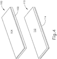
FIG. 4 depicts a perspective view of an exemplary upper buttress and an exemplary lower buttress, each of which may be applied to the end effector ofFIG. 2 ; -
FIG. 5A depicts a cross-sectional end view of a portion of the end effector ofFIG. 2 with a buttress assembly formed by the buttresses ofFIG. 4 applied to the end effector, with tissue positioned between the buttresses in the end effector, and with the anvil in an open position; -
FIG. 5B depicts a cross-sectional end view of the combined end effector and buttress assembly ofFIG. 5A , with tissue positioned between the buttresses in the end effector, and with the anvil in a closed position; -
FIG. 5C depicts a cross-sectional view of a staple and the buttress assembly ofFIG. 5A having been secured to the tissue by the end effector ofFIG. 2 ; -
FIG. 6 depicts a perspective view of staples and the buttress assembly ofFIG. 5A having been secured to the tissue by the end effector ofFIG. 2 ; -
FIG. 7 depicts a perspective view of an exemplary buttress applier cartridge that may be used to carry and apply the buttress assembly ofFIG. 5A ; -
FIG. 8 depicts a top plan view of the buttress applier cartridge ofFIG. 7 ; -
FIG. 9 depicts an exploded perspective view of the buttress applier cartridge ofFIG. 7 ; -
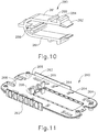
FIG. 10 depicts a perspective view of a sled retainer of the buttress applier cartridge ofFIG. 7 ; -
FIG. 11 depicts a perspective view of a chassis of the buttress applier cartridge ofFIG. 7 ; -
FIG. 12 depicts a top plan view of an actuator sled of the buttress applier cartridge ofFIG. 7 ; -
FIG. 13 depicts a perspective view of a retainer of the buttress applier cartridge ofFIG. 7 ; -
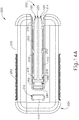
FIG. 14A depicts a top plan view of the buttress applier cartridge ofFIG. 7 , with a buttress assembly loaded on a platform of the buttress applier cartridge, and with retainers positioned to secure the buttress assembly to the platform; -
FIG. 14B depicts a top plan view of the buttress applier cartridge ofFIG. 7 , with a buttress assembly loaded on a platform of the buttress applier cartridge, and with retainers positioned to release the buttress assembly to the platform; -
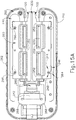
FIG. 15A depicts a top plan view of the buttress applier cartridge ofFIG. 7 , with a housing member removed, with a buttress assembly loaded on a platform of the buttress applier cartridge, and with retainers positioned to secure the buttress assembly to the platform; -
FIG. 15B depicts a top plan view of the buttress applier cartridge ofFIG. 7 , with a housing member removed, with a buttress assembly loaded on a platform of the buttress applier cartridge, and with retainers positioned to release the buttress assembly to the platform; -
FIG. 16A depicts a perspective view of the end effector ofFIG. 2 and the buttress applier cartridge ofFIG. 7 , with the end effector approaching the buttress applier cartridge; -
FIG. 16B depicts a perspective view of the end effector ofFIG. 2 and the buttress applier cartridge ofFIG. 7 , with the buttress applier cartridge positioned in the end effector; -
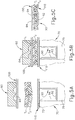
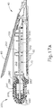
FIG. 17A depicts a cross-sectional side view of the end effector ofFIG. 2 and the buttress applier cartridge ofFIG. 7 , with the buttress applier cartridge positioned in the end effector, and with the end effector in an open configuration; -
FIG. 17B depicts a cross-sectional side view of the end effector ofFIG. 2 and the buttress applier cartridge ofFIG. 7 , with the buttress applier cartridge positioned in the end effector, and with the end effector in a closed configuration; -
FIG. 18 depicts a cross-sectional end view of another exemplary alternative buttress applier cartridge, with a platform of the buttress applier cartridge positioned in the end effector ofFIG. 2 ; and -
FIG. 19 depicts a perspective view of another exemplary alternative buttress applier cartridge. - The drawings are not intended to be limiting in any way, and it is contemplated that various embodiments of the invention may be carried out in a variety of other ways, including those not necessarily depicted in the drawings. The accompanying drawings incorporated in and forming a part of the specification illustrate several aspects of the present invention, and together with the description serve to explain the principles of the invention; it being understood, however, that this invention is not limited to the precise arrangements shown.
- The following description of certain examples of the invention should not be used to limit the scope of the present invention. Other examples, features, aspects, embodiments, and advantages of the invention will become apparent to those skilled in the art from the following description, which is by way of illustration, one of the best modes contemplated for carrying out the invention. As will be realized, the invention is capable of other different and obvious aspects, all without departing from the invention. Accordingly, the drawings and descriptions should be regarded as illustrative in nature and not restrictive.
-
FIG. 1 depicts an exemplary surgical stapling and severing instrument (10) that includes a handle assembly (20), a shaft assembly (30), and an end effector (40). End effector (40) and the distal portion of shaft assembly (30) are sized for insertion, in a nonarticulated state as depicted inFIG. 1 , through a trocar cannula to a surgical site in a patient for performing a surgical procedure. By way of example only, such a trocar may be inserted in a patient's abdomen, between two of the patient's ribs, or elsewhere. In some settings, instrument (10) is used without a trocar. For instance, end effector (40) and the distal portion of shaft assembly (30) may be inserted directly through a thoracotomy or other type of incision. It should be understood that terms such as "proximal" and "distal" are used herein with reference to a clinician gripping handle assembly (20) of instrument (10). Thus, end effector (40) is distal with respect to the more proximal handle assembly (20). It will be further appreciated that for convenience and clarity, spatial terms such as "vertical" and "horizontal" are used herein with respect to the drawings. However, surgical instruments are used in many orientations and positions, and these terms are not intended to be limiting and absolute. - As shown in
FIG. 1 , handle assembly (20) of the present example comprises pistol grip (22), a closure trigger (24), and a firing trigger (26). Each trigger (24, 26) is selectively pivotable toward and away from pistol grip (22) as will be described in greater detail below. Handle assembly (20) further includes a removable battery pack (28). These components will also be described in greater detail below. Of course, handle assembly (20) may have a variety of other components, features, and operabilities, in addition to or in lieu of any of those noted above. Other suitable configurations for handle assembly (20) will be apparent to those of ordinary skill in the art in view of the teachings herein. - As shown in
FIGS. 1-2 , shaft assembly (30) of the present example comprises an outer closure tube (32), an articulation section (34), and a closure ring (36), which is further coupled with end effector (40). Closure tube (32) extends along the length of shaft assembly (30). Closure ring (36) is positioned distal to articulation section (34). Closure tube (32) and closure ring (36) are configured to translate longitudinally relative to handle assembly (20). Longitudinal translation of closure tube (32) is communicated to closure ring (36) via articulation section (34). Exemplary features that may be used to provide longitudinal translation of closure tube (32) and closure ring (36) will be described in greater detail below. - Articulation section (34) is operable to laterally deflect closure ring (36) and end effector (40) laterally away from the longitudinal axis (LA) of shaft assembly (30) at a desired angle (α). In the present example, articulation is controlled through an articulation control knob (35) which is located at the proximal end of shaft assembly (30). Closure ring (36) and end effector (40) pivot about an axis that is perpendicular to the longitudinal axis (LA) of shaft assembly (30) in response to rotation of knob (35). Articulation section (34) is configured to communicate longitudinal translation of closure tube (32) to closure ring (36), regardless of whether articulation section (34) is in a straight configuration or an articulated configuration. By way of example only, articulation section (34) and/or articulation control knob (35) may be constructed and operable in accordance with at least some of the teachings of
U.S. Pub. No. 2014/0243801 , entitled "Surgical Instrument End Effector Articulation Drive with Pinion and Opposing Racks," published August 28, 2014; and/orU.S. Patent pub No. 2015-0374360 (Pat. App. No.14/314,125 - As shown in
FIG. 1 , shaft assembly (30) of the present example further includes a rotation knob (31). Rotation knob (31) is operable to rotate the entire shaft assembly (30) and end effector (40) relative to handle assembly (20) about the longitudinal axis (LA) of shaft assembly (30). Of course, shaft assembly (30) may have a variety of other components, features, and operabilities, in addition to or in lieu of any of those noted above. By way of example only, at least part of shaft assembly (30) is constructed in accordance with at least some of the teachings ofU.S. Pub. No. 2014/0239038 , entitled "Surgical Instrument with Multi-Diameter Shaft," published August 28, 2014. Other suitable configurations for shaft assembly (30) will be apparent to those of ordinary skill in the art in view of the teachings herein. - As also shown in
FIGS. 1-3 , end effector (40) of the present example includes a lower jaw (50) and a pivotable anvil (60). Anvil (60) includes a pair of integral, outwardly extending pins (66) that are disposed in corresponding curved slots (54) of lower jaw (50). Anvil (60) is pivotable toward and away from lower jaw (50) between an open position (shown inFIG. 2 ) and a closed position (shown inFIG. 1 ). Use of the term "pivotable" (and similar terms with "pivot" as a base) should not be read as necessarily requiring pivotal movement about a fixed axis. For instance, in the present example, anvil (60) pivots about an axis that is defined by pins (66), which slide along curved slots (54) of lower jaw (50) as anvil (60) moves toward lower jaw (50). In such versions, the pivot axis translates along the path defined by slots (54) while anvil (60) simultaneously pivots about that axis. In addition or in the alternative, the pivot axis may slide along slots (54) first, with anvil (60) then pivoting about the pivot axis after the pivot axis has slid a certain distance along the slots (54). It should be understood that such sliding/translating pivotal movement is encompassed within terms such as "pivot," "pivots," "pivotal," "pivotable," "pivoting," and the like. Of course, some versions may provide pivotal movement of anvil (60) about an axis that remains fixed and does not translate within a slot or channel, etc. - As best seen in
FIG. 3 , lower jaw (50) of the present example defines a channel (52) that is configured to receive a staple cartridge (70). Staple cartridge (70) may be inserted into channel (52), end effector (40) may be actuated, and then staple cartridge (70) may be removed and replaced with another staple cartridge (70). Lower jaw (50) thus releasably retains staple cartridge (70) in alignment with anvil (60) for actuation of end effector (40). In some versions, lower jaw (50) is constructed in accordance with at least some of the teachings ofU.S. Pub. No. 2014/0239044 , entitled "Installation Features for Surgical Instrument End Effector Cartridge," published August 28, 2014. Other suitable forms that lower jaw (50) may take will be apparent to those of ordinary skill in the art in view of the teachings herein. - As best seen in
FIGS. 2-3 , staple cartridge (70) of the present example comprises a cartridge body (71) and a tray (76) secured to the underside of cartridge body (71). The upper side of cartridge body (71) presents a deck (73), against which tissue may be compressed when anvil (60) is in a closed position. Cartridge body (71) further defines a longitudinally extending channel (72) and a plurality of staple pockets (74). A staple (90) is positioned in each staple pocket (74). A staple driver (75) is also positioned in each staple pocket (74), underneath a corresponding staple (90), and above tray (76). As will be described in greater detail below, staple drivers (75) are operable to translate upwardly in staple pockets (74) to thereby drive staples (90) upwardly through staple pockets (74) and into engagement with anvil (60). Staple drivers (75) are driven upwardly by a wedge sled (78), which is captured between cartridge body (71) and tray (76), and which translates longitudinally through cartridge body (71). - Wedge sled (78) includes a pair of obliquely angled cam surfaces (79), which are configured to engage staple drivers (75) and thereby drive staple drivers (75) upwardly as wedge sled (78) translates longitudinally through cartridge (70). For instance, when wedge sled (78) is in a proximal position, staple drivers (75) are in downward positions and staples (90) are located in staple pockets (74). As wedge sled (78) is driven to the distal position by a translating knife member (80), wedge sled (78) drives staple drivers (75) upwardly, thereby driving staples (90) out of staple pockets (74) and into staple forming pockets (64) that are formed in the underside (65) of anvil (60). Thus, staple drivers (75) translate along a vertical dimension as wedge sled (78) translates along a horizontal dimension.
- In some versions, staple cartridge (70) is constructed and operable in accordance with at least some of the teachings of U.
U.S. Pub. No. 2014/0239042 , entitled "Integrated Tissue Positioning and Jaw Alignment Features for Surgical Stapler," published August 28, 2014. In addition or in the alternative, staple cartridge (70) may be constructed and operable in accordance with at least some of the teachings ofU.S. Pub. No. 2014/0239044 , entitled "Installation Features for Surgical Instrument End Effector Cartridge," published August 28, 2014. Other suitable forms that staple cartridge (70) may take will be apparent to those of ordinary skill in the art in view of the teachings herein. - As best seen in
FIG. 2 , anvil (60) of the present example comprises a longitudinally extending channel (62) and a plurality of staple forming pockets (64). Channel (62) is configured to align with channel (72) of staple cartridge (70) when anvil (60) is in a closed position. Each staple forming pocket (64) is positioned to lie over a corresponding staple pocket (74) of staple cartridge (70) when anvil (60) is in a closed position. Staple forming pockets (64) are configured to deform the legs of staples (90) when staples (90) are driven through tissue and into anvil (60). In particular, staple forming pockets (64) are configured to bend the legs of staples (90) to secure the formed staples (90) in the tissue. Anvil (60) may be constructed in accordance with at least some of the teachings ofU.S. Pub. No. 2014/0239042 , entitled "Integrated Tissue Positioning and Jaw Alignment Features for Surgical Stapler," published August 28, 2014; at least some of the teachings ofU.S. Pub. No. 2014/0239036 , entitled "Jaw Closure Feature for End Effector of Surgical Instrument," published August 28, 2014; and/or at least some of the teachings ofU.S. Pub. No. 2014/0239037 , entitled "Staple Forming Features for Surgical Stapling Instrument," published August 28, 2014. Other suitable forms that anvil (60) may take will be apparent to those of ordinary skill in the art in view of the teachings herein. - In the present example, a knife member (80) is configured to translate through end effector (40). As best seen in
FIG. 3 , knife member (80) is secured to the distal end of a firing beam (82), which extends through a portion of shaft assembly (30). As best seen inFIG. 2 , knife member (80) is positioned in channels (62, 72) of anvil (60) and staple cartridge (70). Knife member (80) includes a distally presented cutting edge (84) that is configured to sever tissue that is compressed between anvil (60) and deck (73) of staple cartridge (70) as knife member (80) translates distally through end effector (40). As noted above, knife member (80) also drives wedge sled (78) distally as knife member (80) translates distally through end effector (40), thereby driving staples (90) through tissue and against anvil (60) into formation. - In the present example, anvil (60) is driven toward lower jaw (50) by advancing closure ring (36) distally relative to end effector (40). Closure ring (36) cooperates with anvil (60) through a camming action to drive anvil (60) toward lower jaw (50) in response to distal translation of closure ring (36) relative to end effector (40). Similarly, closure ring (36) may cooperate with anvil (60) to open anvil (60) away from lower jaw (50) in response to proximal translation of closure ring (36) relative to end effector (40). By way of example only, closure ring (36) and anvil (60) may interact in accordance with at least some of the teachings of
U.S. Pub. No. 2014/0239036 , entitled "Jaw Closure Feature for End Effector of Surgical Instrument," published August 28, 2014; and/or in accordance with at least some of the teachings ofU.S. Patent pub No. 2015-0374373 (Patent App. No.14/314,108 - As noted above, handle assembly (20) includes a pistol grip (22) and a closure trigger (24). As also noted above, anvil (60) is closed toward lower jaw (50) in response to distal advancement of closure ring (36). In the present example, closure trigger (24) is pivotable toward pistol grip (22) to drive closure tube (32) and closure ring (36) distally. Various suitable components that may be used to convert pivotal movement of closure trigger (24) toward pistol grip (22) into distal translation of closure tube (32) and closure ring (36) relative to handle assembly (20) will be apparent to those of ordinary skill in the art in view of the teachings herein.
- Also in the present example, instrument (10) provides motorized control of firing beam (82). In particular, instrument (10) includes motorized components that are configured to drive firing beam (82) distally in response to pivoting of firing trigger (26) toward pistol grip (22). In some versions, a motor (not shown) is contained in pistol grip (22) and receives power from battery pack (28). This motor is coupled with a transmission assembly (not shown) that converts rotary motion of a drive shaft of the motor into linear translation of firing beam (82). By way of example only, the features that are operable to provide motorized actuation of firing beam (82) may be configured and operable in accordance with at least some of the teachings of
U.S. Pat. No. 8,210,411 , entitled "Motor-Driven Surgical Instrument," issued July 3, 2012;U.S. Pat. No. 8,453,914 , entitled "Motor-Driven Surgical Cutting Instrument with Electric Actuator Directional Control Assembly," issued June 4, 2013; and/orU.S. Patent pub No. 2015-0272575 (Patent App. No.14/226,142 - It should also be understood that any other components or features of instrument (10) may be configured and operable in accordance with any of the various references cited herein. Additional exemplary modifications that may be provided for instrument (10) will be described in greater detail below. Various suitable ways in which the below teachings may be incorporated into instrument (10) will be apparent to those of ordinary skill in the art. Similarly, various suitable ways in which the below teachings may be combined with various teachings of the references cited herein will be apparent to those of ordinary skill in the art. It should therefore be understood that the teachings below may be readily incorporated into the various instruments taught in the various references that are cited herein. It should also be understood that the below teachings are not limited to instrument (10) or devices taught in the references cited herein. The below teachings may be readily applied to various other kinds of instruments, including instruments that would not be classified as surgical staplers. Various other suitable devices and settings in which the below teachings may be applied will be apparent to those of ordinary skill in the art in view of the teachings herein.
- In some instances, it may be desirable to equip end effector (40) with a buttress material to reinforce the mechanical fastening of tissue provided by staples (90). Such a buttress may prevent the applied staples (90) from pulling through the tissue and may otherwise reduce a risk of tissue tearing at or near the site of applied staples (90). In addition to or as an alternative to providing structural support and integrity to a line of staples (90), a buttress may provide various other kinds of effects such as spacing or gap-filling, administration of therapeutic agents, and/or other effects. In some instances, a buttress may be provided on deck (73) of staple cartridge (70). In some other instances, a buttress may be provided on the surface of anvil (60) that faces staple cartridge (70). It should also be understood that a first buttress may be provided on deck (73) of staple cartridge (70) while a second buttress is provided on anvil (60) of the same end effector (40). Various examples of forms that a buttress may take will be described in greater detail below. Various ways in which a buttress may be secured to a staple cartridge (70) or an anvil (60) will also be described in greater detail below.
-
FIG. 4 shows an exemplary pair of buttress assemblies (100, 110) with a basic composition. Buttress assembly (100) of this example comprises a buttress body (102) and an upper adhesive layer (104). Similarly, buttress assembly (110) comprises a buttress body (112) and a lower adhesive layer (114). In the present example, each buttress body (102, 112) comprises a strong yet flexible material configured to structurally support a line of staples (90). By way of example only, each buttress body (102, 112) may comprise a woven mesh of polyglactin 910 material by Ethicon, Inc. of Somerville, New Jersey. Alternatively, any other suitable materials or combinations of materials may be used in addition to or as an alternative to polyglactin 910 material to form each buttress body (102, 112). Each buttress body (102, 112) may take any other suitable form and may be constructed of any other suitable material(s). By way of further example only, each buttress body (102, 112) may comprise one or more of the following: NEOVEIL absorbable PGA felt by Gunze Limited, of Kyoto, Japan; SEAMGUARD polyglycolic acid:trimethylene carbonate (PGA:TMC) reinforcement material by W.L. Gore & Associates, Inc., of Flagstaff, Arizona; PERI-STRIPS DRY with VERITAS Collagen Matrix (PSDV) reinforcement material, by Baxter Healthcare Corporation of Deerfield, Illinois; BIODESIGN biologic graft material by Cook Medical, Bloomington, Indiana; and/or SURGICEL NU-KNIT hemostat material by Ethicon, Inc. of Somerville, New Jersey. Still other suitable materials that may be used to form each buttress body (102, 112) will be apparent to those of ordinary skill in the art in view of the teachings herein. - In addition or in the alternative, each buttress body (102, 112) may comprise a material including, for example, a hemostatic agent such as fibrin to assist in coagulating blood and reduce bleeding at the severed and/or stapled surgical site along tissue (90). As another merely illustrative example, each buttress body (102, 112) may comprise other adjuncts or hemostatic agents such as thrombin may be used such that each buttress body (102, 112) may assist to coagulate blood and reduce the amount of bleeding at the surgical site. Other adjuncts or reagents that may be incorporated into each buttress body (102, 112) may further include but are not limited to medical fluid or matrix components. Merely illustrative examples of materials that may be used to form each buttress body (102, 112), as well as materials that may be otherwise incorporated into each buttress body (102, 112), are disclosed in
U.S. Patent pub No. 2016-0278774 (Patent App. No.14/667,842 - By way of further example only, each buttress body (102, 112) may be constructed in accordance with at least some of the teachings of
U.S. Patent Pub. No. 2012/0241493 , entitled "Tissue Thickness Compensator Comprising Controlled Release and Expansion," published September 27, 2012;U.S. Patent Pub. No. 2013/0068816 , entitled "Surgical Instrument and Buttress Material," published March 21, 2013;U.S. Patent Pub. No. 2013/0062391 , entitled "Surgical Instrument with Fluid Fillable Buttress," published March 14, 2013;U.S. Patent Pub. No. 2013/0068820 , entitled "Fibrin Pad Matrix with Suspended Heat Activated Beads of Adhesive," published March 21, 2013;U.S. Patent Pub. No. 2013/0082086 , entitled "Attachment of Surgical Staple Buttress to Cartridge," published April 4, 2013;U.S. Patent Pub. No. 2013/0037596 , entitled "Device for Applying Adjunct in Endoscopic Procedure," published February 14, 2013;U.S. Patent Pub. No. 2013/0062393 , entitled "Resistive Heated Surgical Staple Cartridge with Phase Change Sealant," published March 14, 2013;U.S. Patent Pub. No. 2013/0075446 , entitled "Surgical Staple Assembly with Hemostatic Feature," published March 28, 2013;U.S. Patent Pub. No. 2013/0062394 , entitled "Surgical Staple Cartridge with Self-Dispensing Staple Buttress," published March 14, 2013;U.S. Patent Pub. No. 2013/0075445 , entitled "Anvil Cartridge for Surgical Fastening Device," published March 28, 2013;U.S. Patent Pub. No. 2013/0075447 , entitled "Adjunct Therapy for Applying Hemostatic Agent," published March 28, 2013;U.S. Patent Pub. No. 2013/0256367 , entitled "Tissue Thickness Compensator Comprising a Plurality of Medicaments," published October 3, 2013;U.S. Patent pub No. 2015-0351758 (Patent Application No.14/300,954 U.S. Patent App. No. 14/827,856 U.S. Patent pub No. 2017-0055986 (Patent Application No.14/840,613 U.S. Patent pub No. 2017-0086837 (Patent App. No.14/871,071 U.S. Patent pub No. 2017-0086842 (Patent App. No.14/871,131 - In the present example, adhesive layer (104) is provided on buttress body (102) in order to adhere buttress body (102) to underside (65) of anvil (60). Similarly, adhesive layer (114) is provided on buttress body (112) in order to adhere buttress body (112) to deck (73) of staple cartridge (70). Adherence of the buttress body (102) to underside (65) of anvil (60) or to deck (73) of staple cartridge (70) can occur through a variety of mechanisms including but not limited to a pressure sensitive adhesive. In some versions, each adhesive layer (104, 114) comprise a pressure sensitive adhesive material. Examples of various suitable materials that may be used to form adhesive layers (104, 114) are disclosed in
U.S. Patent pub No. 2016-0278774 (Patent App. No.14/667,842 - As noted above, a buttress assembly (100, 110) may include a layer (104, 114) of adhesive material (or other form of adhesive material) that adheres buttress body (102, 112) to either underside (65) of anvil (60) or deck (73) of staple cartridge (70). Such an adhesive material may provide proper positioning of buttress body (102, 112) before and during actuation of end effector (40); then allow buttress body (102, 112) to separate from end effector (40) after end effector (40) has been actuated, without causing damage to buttress body (102, 112) that is substantial enough to compromise the proper subsequent functioning of buttress body (102, 112).
-
FIGS. 5A-5C show a sequence where an end effector (40) that has been loaded with buttress assemblies (100, 110) is actuated to drive staples (90) through two apposed layers of tissue (T1, T2), with buttress assemblies (100, 110) being secured to the same layers of tissue (T1, T2) by staples (90). In particular,FIG. 5A shows layers of tissue (T1, T2) positioned between anvil (60) and staple cartridge (70), with anvil (60) in the open position. Buttress assembly (100) is adhered to the underside (65) of anvil (60) via adhesive layer (104); while buttress assembly (110) is adhered to deck (73) of staple cartridge (70) via adhesive layer (114). Layers of tissue (T1, T2) are thus interposed between buttress assemblies (100, 110). Next, trigger (24) is pivoted toward pistol grip (22) to drive closure tube (32) and closure ring (36) distally. This drives anvil (60) to the closed position as shown inFIG. 5B . At this stage, layers of tissue (T1, T2) are compressed between anvil (60) and staple cartridge (70), with buttress assemblies (100, 110) engaging opposite surfaces of tissue layers (T1, T2). End effector (40) is then actuated as described above, driving staple (90) through buttress assemblies (100, 110) and tissue (90). As shown inFIG. 5C , crown (92) of driven staple (90) captures and retains buttress assembly (110) against layer of tissue (T2). Deformed legs (94) of staple (90) capture and retain buttress assembly (100) against layer of tissue (T1). - It should be understood that a series of staples (90) will similarly capture and retain buttress assemblies (100, 110) against layers of tissue (T1, T2), thereby securing buttress assemblies (100, 110) to tissue (T1, T2) as shown in
FIG. 6 . As end effector (40) is pulled away from tissue (90) after deploying staples (90) and buttress assemblies (100, 110), buttress assemblies (100, 110) disengage end effector), such that buttress assemblies (100, 110) remain secured to tissue (T1, T2) with staples (90). Buttress tissue (T1, T2) thus provide structural reinforcement to the lines of staples (90). As can also be seen inFIG. 6 , knife member (80) also cuts through a centerline of buttress tissue assemblies (100, 110), separating each buttress assemblies (100, 110) into a corresponding pair of sections, such that each section remains secured to a respective severed region of tissue (T1, T2). - In the foregoing example, buttress assembly (100) is sized to span across the full width of underside (65), such that buttress assembly (100) spans across channel (62). Thus, knife member (80) cuts through buttress assembly (100) during actuation of end effector (40) as described above. In some other examples, such as those described below, buttress assembly (100) is provided in two separate, laterally spaced apart portions, with one portion being disposed on underside (65) on one side of channel (62) and another portion being disposed on underside (65) on the other side of channel (62). In such versions, buttress assembly (100) does not span across channel (62), such that knife member (80) does not cut through buttress assembly (100) during actuation of end effector (40).
- Likewise, buttress assembly (110) may be sized to span across the full width of deck (73), such that buttress assembly (110) spans across channel (72), and such that knife member (80) cuts through buttress assembly (110) during actuation of end effector (40) as described above. Alternatively, buttress assembly (110) may be provided in two separate, laterally spaced apart portions, with one portion being disposed on deck (73) on one side of channel (72) and another portion being disposed on deck (73) on the other side of channel (72), such that buttress assembly (110) does not span across channel (72), and such that knife member (80) does not cut through buttress assembly (110) during actuation of end effector (40).
- In addition to the foregoing, it should also be understood that any of the various buttress assemblies described herein may be further constructed and operable in accordance with at least some of the teachings of
U.S. Patent pub No. 2016-0278774 (Patent App. No.14/667,842 - As noted above, buttress assembly (100) may be applied to the underside (65) of anvil (60), and buttress (110) may be applied to deck (73) of staple cartridge (70), before tissue (T1, T2) is positioned in end effector (40), and before end effector (40) is actuated. Because end effector (40) may be actuated many times during use of instrument (10) in a single surgical procedure, it may be desirable to enable an operator to repeatedly and easily load buttress assemblies (100) on underside (65) of anvil (60) during that single surgical procedure. In other words, because end effector (40) may be actuated many times during use of instrument (10) in a single surgical procedure, it may be insufficient to simply provide anvil (60) pre-loaded with a buttress assembly (100) without facilitating the re-loading of anvil (60) with additional buttress assemblies (100) after end effector (40) has been actuated.
- Similarly, those of ordinary skill in the art will recognize that staple cartridge (70) will need to be replaced each time end effector (40) is actuated. When end effector (40) is actuated several times during use of instrument (10) in a single surgical procedure, several staple cartridges (70) may thus be used during that surgical procedure. It may seem that each of these staple cartridges (70) may be provided with buttress assembly (110) pre-loaded on deck (73). However, there are some reasons why it may be undesirable to provide a staple cartridge (70) with buttress assembly (110) pre-loaded on deck (73). In other words, it may be desirable to provide loading of buttress assembly (110) on deck (73) immediately prior to usage of staple cartridge in the surgical procedure, rather than loading buttress assembly (110) on deck (73) a substantial time prior to the surgical procedure. For instance, buttress assembly (110) may not be compatible with the same sterilization techniques as staple cartridge (70), such that it may present processing difficulties to package staple cartridge (70) with buttress assembly (110) pre-loaded on deck (73). In addition, the material forming buttress assembly (110) may have certain environmental sensitivities that staple cartridge (70) does not have, such that it may be beneficial to enable buttress assembly (110) and staple cartridge (70) to be stored separately before use. Moreover, buttress assembly (110) may not be warranted or otherwise desired in some surgical procedures, such that it may be desirable to enable a physician to easily choose whether staple cartridge (70) should be loaded with buttress assembly (110) before that staple cartridge (70) is used in the surgical procedure.
- In view of the foregoing, it may be desirable to enable an operator to repeatedly and easily load buttress assemblies (100, 110) on end effector (40) on an ad hoc basis during a given surgical procedure. It may also be desirable to provide a device that provides support and protection to buttress assemblies (100, 110) before buttress assemblies (100, 110) are loaded on end effector (40), in addition to that same device also enabling buttress assemblies (100, 110) to be easily loaded on end effector. The examples described below relate to various cartridge assemblies that provide such support, protection, and loading of buttress assemblies (100, 110). It should be understood that the following examples are merely illustrative. Numerous variations will be apparent to those of ordinary skill in the art in view of the teachings herein.
-
FIGS. 7-17B show an exemplary buttress applier cartridge (200) that may be used to support and protect buttress assemblies (100, 110). Cartridge (200) may also be used to easily load buttress assemblies (100, 110) on end effector (40). As best seen inFIGS. 7-8 , cartridge (200) of this example comprises an open end (202) and a closed end (204). Open end (202) is configured to receive end effector (40) as will be described in greater detail below. Cartridge (200) further includes a first housing (210) and a second housing (218), which each generally define a "U" shape to present open end (202). As best seen inFIG. 9 , various components are interposed between housings (210, 218). In particular, these components include a platform (220), a pair of actuator sleds (240), a pair of retainers (250), a chassis (260), and a sled retainer (280). Each of these components will be described in greater detail below. - Platform (220) of the present example is configured to support a pair of buttress assemblies (100) on one side of platform (220) and another pair of buttress assemblies (110) on the other side of platform (220). Platform (220) is exposed in recesses that are formed between the prongs of the "U" configuration of housings (210, 218). The location of platform (220) and buttress assemblies (100, 110) in such recesses may prevent inadvertent contact between buttress assemblies (100, 110) and other devices in the operating room. In other words, housings (210, 218) may provide some degree of physical shielding of buttress assemblies (100, 110).
- In the present example, each buttress assembly (100, 110) is provided in a respective pair of portions that are separated to avoid spanning across channels (62, 72) of anvil (60) and staple cartridge (70), respectively, though it should be understood that platform (220) may just as easily support wide versions of buttress assemblies (100, 110) that unitarily span across channels (62, 72) of anvil (60) and staple cartridge (70), respectively. The outer edges of platform (220) are captured between housings (210, 218) and include retention features (222) in the form of ridges that further engage housings (210, 218) to prevent platform (220) from sliding relative to housings (210, 218). In some versions, platform (220) is formed of a material that provides a high coefficient of friction, thereby reducing any tendency that buttress assemblies (100, 110) might otherwise have to slide along corresponding surfaces of platform (220). For instance, platform (220) may comprise an elastomeric material and/or a foam material. In some instances, platform (220) is formed of a compressible foam material that is configured to maintain a compressed configuration after being compressed by end effector (40). By way of example only, platform (220) may comprise Santoprene, closed-cell polyurethane foam, any other compressible material, and/or a material that may be made compressible via geometry (e.g., a rubber material with deformable standing features). Various suitable materials and structural configurations that may be used to form platform (220) will be apparent to those of ordinary skill in the art in view of the teachings herein.
- Chassis (260) is configured to cooperate with housings (210, 218) to provide a mechanical ground for moving components of cartridge (200) and provide structural support for components of cartridge (200). As shown in
FIGS. 7-8 , chassis (260) includes integral gripping features (262) that are exposed on opposite sides of housings (210, 218). Gripping features (262) have a surface geometry that is configured to promote an operator's grip of cartridge (200) during use of cartridge (200). Various suitable configurations that may be used for gripping features (262) will be apparent to those of ordinary skill in the art in view of the teachings herein. Similarly, various surface treatments (e.g., elastomeric material, etc.) that may be applied to gripping features (262) will be apparent to those of ordinary skill in the art in view of the teachings herein. As best seen inFIG. 11 , chassis (260) further includes a set of laterally oriented slots (264), a first pair of bosses (266), and a second pair of bosses (268). Slots (264) are configured to slidably receive pins (296) as shown inFIG.S 9 and15A-15B . In particular, pins (296) may translate laterally within slots (264) (i.e. toward and away from the central longitudinal axis extending along the center of platform (220)). In the present example, there are six slots (264) and only four pins (296), such that two of the slots (264) are not used. In other versions, there are six pins (296) such that all six slots (264) are used. In still other versions, there are only four slots (264), corresponding with the four pins (296) of the present example. - Actuator sleds (240) are slidably positioned on opposite faces of chassis (260). As shown in
FIG. 12 , each actuator sled includes a locking recess (241), a set of slots (244), and a pair of boss features (249). As shown inFIG. 9 , a set of coil springs (298) are positioned between bosses (266) of chassis (260) and boss features (249) of actuator sled (240). Coil springs (298) resiliently bias actuator sleds (240) proximally relative to chassis (260). As will be described in greater detail below, locking recess (241) is configured to selectively engage a locking ridge (286) of sled retainer (280) to selectively lock the longitudinal position of actuator sleds (240) relative to chassis (260), thereby resisting the resilient bias of coil springs (298). As shown inFIGS. 9 and15A-15B , an indicator plate (242) is secured to the proximal end of each actuator sled (240), such that indicator plates (242) will translate unitarily with actuator sleds (240). Indicator plates (242) are positioned to correspond with windows (212) that are formed in housings (210, 218), such that indicator plates (242) are visible through windows (212) when actuator sleds (240) are in a distal position and when actuator sleds (240) are in a proximal position. As will be described in greater detail below, indicator plates (242) may include different colored regions or other markings that provide visual indication through windows (212), visually indicating whether actuator sleds (240) are in the distal position or the proximal position. - As shown in
FIGS. 9 and15A-15B , slots (244) are positioned to also receive pins (296). Each slot (244) includes a longitudinally extending portion (246) and an obliquely extending portion (248). Pins (296) are configured to travel along the longitudinally extending portion (246) of each corresponding slot (244) and along the obliquely extending portion (248) of each corresponding slot (244). In the present example, there are six slots (244) and only four pins (296), such that two of the slots (244) are not used. In other versions, there are six pins (296) such that all six slots (244) are used. In still other versions, there are only four slots (244), corresponding with the four pins (296) of the present example. - Retainers (250) are slidably disposed on respective actuator sleds (240), such that each actuator sled (240) is slidably interposed between chassis (260) and a corresponding retainer (250). As shown in
FIG. 13 , each retainer (250) includes a set of arms (252) and a set of openings (254). Openings (254) are positioned to receive pins (296). Pins (296) are secured within openings (254) such that pins (296) do not move within corresponding openings (254). Retainers (250) thus travel unitarily with pins (296) in this example, as will be described in greater detail below. In the present example, there are six openings (254) and only four pins (296), such that two of the openings (254) are not used. In other versions, there are six pins (296) such that all six openings (254) are used. In still other versions, there are only four openings (254), corresponding with the four pins (296) of the present example. - Arms (252) of the present example are configured to selectively secure buttress assemblies (100, 110) to platform (220). In particular,
FIGS. 7-8 ,14A , and15A show retainers (250) positioned such that buttress assemblies (100, 110) are interposed between the free ends of arms (252) and platform (220). As described in greater detail below, retainers (250) are movable laterally outwardly such that arms (252) disengage buttress assemblies (100, 110), thereby enabling buttress assemblies (100, 110) to be removed from platform (220). In the present example, arms (252) are resilient and are thus configured to resiliently bear against buttress assemblies (100, 110), thereby pinching buttress assemblies (100, 110) against platform (220). Other suitable ways in which arms (252) may engage buttress assemblies (100, 110) will be apparent to those of ordinary skill in the art in view of the teachings herein. - As shown in
FIG. 10 , sled retainer (280) includes a pair of arms (281) that together generally define a "U" shape. The free end of each arm (281) includes a tapered cam surface (282) and a housing engagement feature (284). As best seen inFIGS. 8 and14A-14B , housing engagement features (284) are positioned to engage corresponding surfaces of housings (210, 218). Each arm (281) further includes a respective locking ridge (286) spaced proximally from the corresponding housing engagement feature (284). Sled retainer (280) further defines a channel (288) in the region where arms (281) meet each other. As shown inFIG. 9 , channel (288) is configured to receive the proximal end of chassis (260). -
FIGS. 14A-17B show cartridge (200) in different stages of operation. In particular,FIGS. 14A ,15A , and17A show cartridge (200) in a configuration where retainer arms (252) are positioned to hold buttress assemblies (100, 110) against platform (220); whileFIGS. 14B ,15B , and17B show cartridge (200) in a configuration where retainer arms (252) are positioned to release buttress assemblies (100, 110) from platform (220). WhileFIGS. 14A-17B only show buttress assembly (100) on platform (220), it should be understood that buttress assembly (110) would be retained on and released from platform (220) in an identical fashion. - To use cartridge (200) to load end effector (40), the operator would first position cartridge (200) and end effector (40) such that end effector is aligned with open end (202) of cartridge (200) as shown in
FIG. 16A . The operator would then advance end effector (40) distally (and/or retract cartridge (200) proximally) to position platform (220) and buttress assemblies (100, 110) between anvil (60) and staple cartridge (70) as shown inFIG. 16B . This will ultimately result in the arrangement shown inFIG. 17A . While end effector (40) is not shown inFIGS. 14A or15A , it should be understood that cartridge (200) is in the same state inFIG. 17A as the state shown inFIGS. 14A and15A . In this state, actuator sleds (240) are in a first longitudinal position (i.e., closer to open end (202)). Coil springs (298) are resiliently urging actuator sleds (240) toward a second longitudinal position (i.e., closer to closed end (204)). However, as best seen inFIG. 17A , locking ridges (286) of sled retainer (280) are disposed in locking recesses (241) of actuator sleds (240), thereby holding actuator sleds (240) in the first longitudinal position. With actuator sleds (240) in the first longitudinal position, retainers (250) are located at inward positions to retain buttress assemblies (100, 110) against platform (220). As shown inFIG. 15A , at this stage, pins (296) are positioned at the inner ends of slots (264) of chassis (260); and in the ends of obliquely extending portions (248) of slots (244). - In order to load buttress assemblies (100, 110) on end effector (40), the operator may simply close end effector (40) by pivoting anvil (60) toward staple cartridge (70), as described above, to reach the state shown in
FIG. 17B . As shown, closure of end effector (40) results in the distal ends of anvil (60) and staple cartridge (70) bearing against cam surfaces (282) of sled retainer (280). This causes arms (281) of sled retainer to deform toward each other, such that locking ridges (286) disengage locking recesses (241) of actuator sleds (240). With locking ridges (286) disengaged from locking recesses (241) of actuator sleds (240), coil springs (298) drive actuator sleds (240) proximally to the second longitudinal position. Actuator sleds (240) engage bosses (268) of chassis (260) when actuator sleds (240) reach the proximal position, such that bosses (268) provide a hard stop. It should be understood that this sudden engagement between actuator sleds (240) and bosses (268) may produce a click or snap sound, providing audible feedback to the operator indicating actuation of cartridge (200). - In the present example, cartridge (200) is configured such that both arms (281) must be deformed toward each other at the same time in order for actuator sleds (240) to be unlocked and thereby permitted to translate proximally to the second longitudinal position. If only one arm (281) is deformed toward the other arm (281), the locking ridge (286) of the non-deformed arm (281) will remain disposed in the corresponding locking recess (241) of actuator sled (240), thereby continuing to hold actuator sled (240) in the first longitudinal position. By requiring both arms (281) to be deformed toward each other at the same time in order for actuator sleds (240) to be unlocked, the configuration of sled retainer (280) will reduce the risk of cartridge (200) being actuated prematurely or inadvertently.
- As best seen in the transition from the view shown in
FIG. 15A (actuator sleds (240) in the first longitudinal position) to the view shown inFIG. 15B (actuator sleds (240) in the second longitudinal position), slots (244) act as cams against pins (296) and thereby drive retainers (250) outwardly as actuator sleds (240) travel proximally. In particular, pins (296) traverse obliquely extending portions (248) of slots (244) and then longitudinally extending portions (246) of slots (244). Obliquely extending portions (248) of slots (244) drive pins (296) outwardly during this range of travel. Since retainers (250) travel unitarily with pins (296), retainers (250) travel outwardly as well. Laterally oriented slots (264) of chassis (260) accommodate the outward lateral movement of pins (296) but prevent pins (296) from moving longitudinally during the transition from the state shown inFIG. 15A to the state shown inFIG. 15B . - Upon reaching the state shown in
FIG. 15B , retainers (250) are disengaged from buttress assemblies (100, 110). This state is also shown inFIG. 14B . It should be understood that end effector (40) is still in the closed configuration at this stage, as also shown inFIG. 17B . Thus, with end effector (40) clamping on both buttress assemblies (100, 110), adhesive layers (104, 114) are adhered to underside (65) of anvil (60) and deck (73) of staple cartridge (70). End effector (40) may then be re-opened (i.e., pivoting anvil (60) away from staple cartridge (70)) and pulled away from cartridge (200). With retainers (250) disengaged from buttress assemblies (100, 110), end effector (40) may freely pull buttress assemblies (100, 110) away from platform (220) as end effector (40) is pulled away from cartridge (200). With buttress assemblies (100, 110) loaded on end effector (40), end effector (40) may then be used as described above with reference toFIGS. 5A-6 . - Referring back to
FIGS. 7-8 , housings (210, 218) of the present example include proximal guide features (214) and distal guide features (216). Guide features (214, 216) are configured to assist in providing proper alignment of end effector (40) with cartridge (200). In particular, guide features (214, 216) are configured to engage the lateral sides of lower jaw (50) and anvil (60) to ensure that the central longitudinal axis of end effector (40) is coplanar with the central longitudinal axis of platform (220). Such alignment will prevent buttress assemblies (100, 110) from being applied to underside (65) or deck (73) in a skewed orientation. In some versions, guide features (214, 216) engage the lateral sides of lower jaw (50) and anvil (60) as soon as end effector (40) is positioned as shown inFIG. 16B (i.e., before anvil (60) is pivoted to the closed position). In some other versions, guide features (214, 216) do not engage the lateral sides of lower jaw (50) and anvil (60) until anvil (60) is pivoted closer to the closed position. In the present example, guide features (214, 216) are unitarily formed features of housings (210, 218). In some other versions, guide features (214, 216) are movable relative to housings (210, 218) and are resiliently biased to provide self-centering guidance to the lateral sides of lower jaw (50) and anvil (60). Various suitable forms that guide features (214, 216) may take will be apparent to those of ordinary skill in the art in view of the teachings herein. - As noted above, indicator plates (242) may include different colored regions or other markings (e.g., text, pictograms, etc.) that provide visual indication through windows (212), visually indicating whether actuator sleds (240) are in the first longitudinal position (
FIG. 15A ) or the second longitudinal position (FIG. 15B ). The operator may thus view indicator plate (242) through window (212) to determine whether cartridge (200) has successfully released buttress assemblies (100, 110). An operator may also view indicator plate (242) through window (212) to determine whether cartridge (200) has been previously used. Various suitable markings that may be provided on indicator plates (242) to provide visual feedback indicating the state of cartridge (200) will be apparent to those of ordinary skill in the art in view of the teachings herein. - In some instances, it may be desirable to configure buttress assembly (100) such that the lateral width of buttress assembly (100) closely matches the lateral width of underside (65) of anvil (60). Likewise, it may be desirable to configure buttress assembly (110) such that the lateral width of buttress assembly (110) closely matches the lateral width of deck (73) of anvil (70). Matching these widths may present little to no margin of error with respect to alignment of end effector (40) with buttress assemblies (100, 110). It may therefore be desirable to provide features that ensure or otherwise promote proper alignment of end effector (40) with buttress assemblies (100, 110). Such alignment may include proper lateral positioning of end effector along a lateral plane (i.e., a plane that is parallel to the planes defined by buttress assemblies (100, 110)). Such alignment may also include proper "yaw" positioning about an axis that is perpendicular to the same lateral plane (i.e., a plane that is parallel to the planes defined by buttress assemblies (100, 110)). Several examples of features that may be used to ensure or otherwise promote proper alignment of end effector (40) with buttress assemblies (100, 110) are described in greater detail below, while other examples will be apparent to those of ordinary skill in the art in view of the teachings herein.
-
FIG. 18 shows a buttress applier cartridge (1500) that includes an upper housing (1510) and a lower housing (1530), with a platform (1520) supporting buttress assemblies (100, 110). Platform (1520) is captured between housings (1510, 1530). Buttress assemblies (100, 110) may be removably secured to platform (1520) using any of the various retention structures or techniques described herein. In the present example, buttress assembly (110) has a wider lateral width than buttress assembly (100). This is due to the fact that buttress assembly (110) is configured to be applied to deck (73) of staple cartridge (70), which has a wider lateral width than underside (65) of anvil (60). - Housing (1510) of the present example includes a pair of inner walls (1512) that together define a laterally extending gap. Housing (1532) also includes a pair of walls (1532) that together define a laterally extending gap. These gaps are sized differently in order to accommodate end effector (40) in only one "roll" orientation (i.e., about the longitudinal axis of cartridge (1500), to ensure that an operator will not inadvertently apply buttress assembly (100) to deck (73) and buttress assembly (110) to underside (65).
FIG. 18 shows how lower jaw (50) defines a lateral width "x." The gap between inner walls (1512) is smaller than that width "x" while the gap between inner walls (1532) is larger than the width "x." Thus, if an operator positions cartridge (1500) in relation to end effector (40) at a roll orientation that is off by 180 degrees, such that buttress assembly (100) is facing deck (73) and buttress assembly (110) is facing underside (65), the operator will be unable to fully clamp end effector (40) onto buttress assemblies (100, 110) since staple cartridge (70) and lower jaw (50) will not fit in the gap between inner walls (1512). - Some versions of buttress assemblies (100, 110) may include features that are sensitive to humidity conditions. For instance, the material forming body (102, 112) may be sensitive to humidity conditions in a way such that the effectiveness of body (102, 112) is adversely affected when body (102, 112) is exposed to humidity for a prolonged period. Similarly, the material forming adhesive layer (104, 114) may be sensitive to humidity conditions in a way such that the effectiveness of adhesive layer (104, 114) is adversely affected when adhesive layer (104, 114) is exposed to humidity for a prolonged period. It may therefore be desirable to incorporate one or more features into a buttress applier cartridge that is/are configured to prevent buttress assemblies (100, 110) from being exposed to humidity for prolonged periods. In addition, it may be desirable to incorporate one or more features into a buttress applier cartridge that is/are configured to indicate if buttress assemblies (100, 110) have been exposed to humidity for prolonged periods. If such an indicator shows that buttress assemblies (100, 110) have been exposed to humidity for prolonged periods, the operator may avoid using those particular buttress assemblies (100, 110).
-
FIG. 19 shows an exemplary buttress applier cartridge (1700) that includes housings (1710, 1718), a platform (1720) supporting a buttress assembly (100), and a plurality of retention features (1752). Retention features (1752) are configured to releasably secure buttress assembly (100) to platform (1720); and may be configured like any of the various retention features described herein. Platform (1720) includes a plurality of fins (1722). Fins (1722) are configured and operable just like fins (624) described above, such that fins (1722) may fit within the sidewalls defining channel (62) to ensure that anvil (60) is properly aligned with buttress assembly (100) as anvil (60) is closed down toward buttress assembly (100) and platform (1720). It should also be understood that the underside of platform (1720) (i.e., the side carrying buttress assembly (110), associated with staple cartridge (70)), may also include fins (1722). Fins (1722) on the underside of platform (1720) may be sized and arranged to fit in channel (72) of staple cartridge (70). Moreover, as will be described in greater detail below, fins (1722) on the underside of platform (1720) may be configured to prevent cartridge (1700) from being used with a staple cartridge (70) that has already been fired. - Cartridge (1700) of the present example further includes a plurality of indicator beads (1742) that are viewable through a window (1712) formed in housing (1710). Indicator beads (1742) are formed of a color-changing desiccant material. In particular, beads (1742) are configured to reflect a first color when beads (1742) are in a substantially dry state; and a second color when beads (1742) are in a wet state. Beads (1742) may transition to a wet state in response to exposure to humidity that is above a threshold that is suitable for buttress assemblies (100, 110). In some versions, beads (1742) will maintain the second color even if the humidity level later drops back below the threshold level. Beads (1742) will thus provide visual indication to the user to indicate that buttress assemblies (100, 110) have been subject to an unacceptable level of humidity. Of course, beads (1742) may also transition from the first color to the second color if beads (1742) are otherwise exposed to fluid, such as spilled medical fluids, bodily fluids from a patient, etc. Various materials that may be used to form beads (1742) will be apparent to those of ordinary skill in the art in view of the teachings herein.
- Cartridge (1700) of the present example further includes a cover (1730) that may be removably secured to housings (1710, 1718). Cover (1730) includes an upper panel (1732) and a lower panel (1734) that are coupled together to define a "U" shape. Cover (1730) is sized and configured to cover the recesses in which platform (1720) and buttress assemblies (100, 110) are disposed when cover (1730) is secured to housings (1710, 1718). Cover (1730) may thus protect buttress assemblies (100, 110) up until an operator is ready to use cartridge (1700). To remove cover (1730), the operator may simply pull cover (1730) away from cartridge (1700). By way of example only, panels (1732, 1734) may be resiliently biased toward each other such that panels (1732, 1734) are oriented to be non-parallel with each other. Thus, panels (1732, 1734) may be deflected away from each other to reach a parallel state when cover (1730) is engaged with housings (1710, 1718), such that panels (1732, 1734) resiliently bear against housings (1710, 1718) to provide a secure fit through friction. Various other suitable configurations that may be used to form cover (1730), and to secure cover (1730) to housings (1710, 1718), will be apparent to those of ordinary skill in the art in view of the teachings herein. It should also be understood that cover (1730) may be used with any of the buttress applier cartridges described herein, such that cover (1730) is not at all limited to cartridge (1700).
- In some versions, cover (1730) comprises a desiccant material that is configured to absorb moisture (e.g., from humidity) and thereby prevent that moisture from reaching buttress assemblies (100, 110). In addition or in the alternative, desiccant material may be incorporated into the material forming platform (1720), the material forming housing (1710), packets or compartments located within a cavity defined by housing (1710, 1718), and/or in various other suitable locations/configurations. By way of example only, silica gel may be included in packets that are located within a cavity defined by housing (1710, 1718). Other suitable desiccant materials that may be incorporated into cartridge (1700) will be apparent to those of ordinary skill in the art in view of the teachings herein. Similarly, various other ways in which one or more desiccant materials may be incorporated into cartridge (1700) will be apparent to those of ordinary skill in the art in view of the teachings herein.
- It should be understood that any one or more of the teachings, expressions, embodiments, examples, etc. described herein may be combined with any one or more of the other teachings, expressions, embodiments, examples, etc. that are described herein. The above-described teachings, expressions, embodiments, examples, etc. should therefore not be viewed in isolation relative to each other. Various suitable ways in which the teachings herein may be combined will be readily apparent to those of ordinary skill in the art in view of the teachings herein.
- In addition to the foregoing, it should also be understood that any of the various buttress assemblies described herein may be further constructed and operable in accordance with at least some of the teachings of
U.S. Patent pub No. 2016-0278774 (Patent App. No.14/667,842 U.S. Patent pub No. 2017-0049444 (Patent App. No.14/827,856 U.S. Patent pub No. 2017-0086837 (Patent App. No.14/871,071
September 30, 2015; andU.S. Patent pub No. 2017-0086842 (Patent App. No.14/871,131 U.S. Provisional Patent App. No. 62/209,041 U.S. Patent pub No. 2017-0086842 (Patent App. No.14/871,131 - Versions of the devices described above may have application in conventional medical treatments and procedures conducted by a medical professional, as well as application in robotic-assisted medical treatments and procedures. By way of example only, various teachings herein may be readily incorporated into a robotic surgical system such as the DAVINCI™ system by Intuitive Surgical, Inc., of Sunnyvale, California. Similarly, those of ordinary skill in the art will recognize that various teachings herein may be readily combined with various teachings of any of the following:
U.S. Pat. No. 5,792,135 , entitled "Articulated Surgical Instrument For Performing Minimally Invasive Surgery With Enhanced Dexterity and Sensitivity," issued August 11, 1998;U.S. Pat. No. 5,817,084 , entitled "Remote Center Positioning Device with Flexible Drive," issued October 6, 1998;U.S. Pat. No. 5,878,193 , entitled "Automated Endoscope System for Optimal Positioning," issued March 2, 1999;U.S. Pat. No. 6,231,565 , entitled "Robotic Arm DLUS for Performing Surgical Tasks," issued May 15, 2001;U.S. Pat. No. 6,783,524 , entitled "Robotic Surgical Tool with Ultrasound Cauterizing and Cutting Instrument," issued August 31, 2004;U.S. Pat. No. 6,364,888 , entitled "Alignment of Master and Slave in a Minimally Invasive Surgical Apparatus," issued April 2, 2002;U.S. Pat. No. 7,524,320 , entitled "Mechanical Actuator Interface System for Robotic Surgical Tools," issued April 28, 2009;U.S. Pat. No. 7,691,098 , entitled "Platform Link Wrist Mechanism," issued April 6, 2010;U.S. Pat. No. 7,806,891 , entitled "Repositioning and Reorientation of Master/Slave Relationship in Minimally Invasive Telesurgery," issued October 5, 2010;U.S. Pub. No. 2013/0012957 , entitled "Automated End Effector Component Reloading System for Use with a Robotic System, published January 10, 2013;U.S. Pub. No. 2012/0199630 , entitled "Robotically-Controlled Surgical Instrument with Force-Feedback Capabilities," published August 9, 2012;U.S. Pub. No. 2012/0132450 , entitled "Shiftable Drive Interface for Robotically-Controlled Surgical Tool," published May 31, 2012;U.S. Pub. No. 2012/0199633 , entitled "Surgical Stapling Instruments with Cam-Driven Staple Deployment Arrangements," published August 9, 2012;U.S. Pub. No. 2012/0199631 , entitled "Robotically-Controlled Motorized Surgical End Effector System with Rotary Actuated Closure Systems Having Variable Actuation Speeds," published August 9, 2012;U.S. Pub. No. 2012/0199632 , entitled "Robotically-Controlled Surgical Instrument with Selectively Articulatable End Effector," published August 9, 2012;U.S. Pub. No. 2012/0203247 , entitled "Robotically-Controlled Surgical End Effector System," published August 9, 2012;U.S. Pub. No. 2012/0211546 , entitled "Drive Interface for Operably Coupling a Manipulatable Surgical Tool to a Robot," published August 23, 2012;U.S. Pub. No. 2012/0138660 , entitled "Robotically-Controlled Cable-Based Surgical End Effectors," published June 7, 2012; and/orU.S. Pub. No. 2012/0205421 , entitled "Robotically-Controlled Surgical End Effector System with Rotary Actuated Closure Systems," published August 16, 2012. - Versions of the devices described above may be designed to be disposed of after a single use, or they can be designed to be used multiple times. Versions may, in either or both cases, be reconditioned for reuse after at least one use. Reconditioning may include any combination of the steps of disassembly of the device, followed by cleaning or replacement of particular pieces, and subsequent reassembly. In particular, some versions of the device may be disassembled, and any number of the particular pieces or parts of the device may be selectively replaced or removed in any combination. Upon cleaning and/or replacement of particular parts, some versions of the device may be reassembled for subsequent use either at a reconditioning facility, or by a user immediately prior to a procedure. Those skilled in the art will appreciate that reconditioning of a device may utilize a variety of techniques for disassembly, cleaning/replacement, and reassembly. Use of such techniques, and the resulting reconditioned device, are all within the scope of the present application.
- By way of example only, versions described herein may be sterilized before and/or after a procedure. In one sterilization technique, the device is placed in a closed and sealed container, such as a plastic or TYVEK bag. The container and device may then be placed in a field of radiation that can penetrate the container, such as gamma radiation, x-rays, or high-energy electrons. The radiation may kill bacteria on the device and in the container. The sterilized device may then be stored in the sterile container for later use. A device may also be sterilized using any other technique known in the art, including but not limited to beta or gamma radiation, ethylene oxide, or steam.
- Having shown and described various embodiments of the present invention, further adaptations of the methods and systems described herein may be accomplished by appropriate modifications by one of ordinary skill in the art without departing from the scope of the present invention. Several of such potential modifications have been mentioned, and others will be apparent to those skilled in the art. For instance, the examples, embodiments, geometrics, materials, dimensions, ratios, steps, and the like discussed above are illustrative and are not required. Accordingly, the scope of the present invention should be considered in terms of the following claims and is understood not to be limited to the details of structure and operation shown and described in the specification and drawings.
Claims (14)
- An apparatus comprising:(a) a housing (210, 218) defining a gap configured to receive a portion of an end effector (40) of a surgical stapler (10);(b) a platform (220), wherein a portion of the platform is exposed in the gap defined by the housing;(c) a buttress assembly (100, 110) positioned on the platform, wherein the buttress assembly is exposed in the gap defined by the housing;(d) at least one retainer member (250) including arms (252) configured to selectively retain the buttress assembly against the platform, wherein the at least one retainer member is further configured to move laterally outwardly such that the arms release the buttress assembly from the platform in response to a clamping action of an end effector positioned in the gap defined by the housing; and(e) a lockout alignment feature (280), wherein the lockout alignment feature is configured to prevent the at least one retainer member from releasing the buttress assembly from the platform unless the end effector is located at a predetermined position in relation to the buttress assembly during clamping of the end effector, wherein the lockout alignment feature comprises a latch, wherein the latch is configured to transition between a latching configuration and a non-latching configuration, wherein the latch is configured to hold the at least one retainer in a position to engage the buttress when the latch is in the latching configuration, wherein the latch is configured to enable the at least one retainer to release the buttress assembly when the latch is in the non-latching configuration.
- The apparatus of claim 1, wherein the lockout alignment feature is configured to engage an end effector (40) positioned in the gap defined by the housing (210, 218) to thereby provide lateral alignment and yaw alignment of the end effector relative to first buttress assembly (100, 110).
- The apparatus of claim 1 or claim 2, wherein the latch (280) has a first cam feature and a second cam feature (282), wherein the first cam feature is positioned and configured to engage an anvil (60) of an end effector positioned in the gap defined by the housing (210, 218), wherein the second cam feature is positioned and configured to engage a staple cartridge (70) of an end effector positioned in the gap defined by the housing.
- The apparatus of claim 3, wherein the latch (280) is configured to require clamping engagement of both an anvil (60) against the first cam feature (282) and a staple cartridge (70) against the second cam feature (282), respectively, in order to transition to the non-latching configuration.
- The apparatus of claim 4, wherein the gap comprises an upper portion and a lower portion, wherein the upper portion has a first width configured to complement a width of an anvil (60) of an end effector of a surgical stapler, wherein the lower portion has a second width configured to complement a width of a lower jaw (50) of an end effector of a surgical stapler, wherein the second width is optionally greater than the first width.
- The apparatus of any preceding claim, wherein the platform (220) is recessed in the gap defined by the housing (210, 218).
- The apparatus of any preceding claim, wherein the buttress assembly (100, 110) comprises:(i) a first longitudinally extending portion, and(ii) a second longitudinally extending portion, wherein the second longitudinally extending portion is laterally spaced apart from the first longitudinally extending portion.
- The apparatus of claim 7, wherein the second longitudinally extending portion is laterally spaced apart from the first longitudinally extending portion by a distance corresponding to a width of a gap defined by a channel (72) formed in an end effector (40) in a surgical stapler.
- The apparatus of claim 8, wherein the lockout alignment feature is positioned between the first and second longitudinally extending portions of the buttress assembly (100, 110).
- The apparatus of claim 9, wherein the lockout alignment feature comprises a longitudinally extending fin or array of fins, wherein the fin or array of fins is configured to fit in a channel formed in an end effector in a surgical stapler.
- The apparatus of any preceding claim, wherein at least a portion of the lockout alignment feature is positioned in the gap defined by the housing (210, 218), wherein the housing optionally defines a U shape, and the portion of the lockout alignment feature that is positioned in the gap defined by the housing is located in a bend region of the U shape.
- The apparatus of any preceding claim, wherein the lockout alignment feature is configured to prevent the at least one retainer member (250) from releasing the buttress assembly (100, 110) from the platform (220) unless the end effector (40) is located at a predetermined longitudinal or lateral position in relation to the buttress assembly during clamping of the end effector.
- The apparatus of any preceding claim, further comprising a cover (1730) removably coupled with the housing (1710, 1718), wherein the cover is configured to cover the gap and thereby shield the buttress assembly (100, 110).
- A method of using a cartridge to apply a buttress assembly to an end effector of a surgical instrument, wherein the cartridge comprises a platform, a retainer member, and a latch, wherein the end effector comprises a first jaw member and a second jaw member, the method comprising:(a) positioning the platform between the first and second jaw members while the first and second jaw members are in an open configuration, wherein the retainer member secures the buttress assembly to the platform during the act of positioning the platform between the first and second jaw members, wherein the latch secures the position of the retainer member during the act of positioning the platform between the first and second jaw members;(b) actuating the end effector to transition the first and second jaw members to a closed configuration about the platform, wherein the act of actuating the end effector to transition the first and second jaw members to the closed configuration comprises:(i) engaging a first portion of the latch with the first jaw member, and(ii) engaging a second portion of the latch with the second jaw member while simultaneously engaging the first portion of the latch with the first jaw member,wherein the simultaneous engagement of the first and second portions of the latch causes the latch to release the retainer member,
wherein the release of the retainer member by the latch causes the retainer member to release the buttress assembly; and(c) actuating the end effector to transition the first and second jaw members back to the open configuration, wherein the buttress assembly is secured to the end effector during the act of actuating the end effector to transition the first and second jaw members back to the open configuration.
Priority Applications (1)
| Application Number | Priority Date | Filing Date | Title |
|---|---|---|---|
| PL16185387T PL3135216T3 (en) | 2015-08-24 | 2016-08-23 | Surgical stapler buttress applicator with multi-point actuated release mechanism |
Applications Claiming Priority (2)
| Application Number | Priority Date | Filing Date | Title |
|---|---|---|---|
| US201562209041P | 2015-08-24 | 2015-08-24 | |
| US14/926,609 US10342532B2 (en) | 2015-08-24 | 2015-10-29 | Surgical stapler buttress applicator with multi-point actuated release mechanism |
Publications (2)
| Publication Number | Publication Date |
|---|---|
| EP3135216A1 EP3135216A1 (en) | 2017-03-01 |
| EP3135216B1 true EP3135216B1 (en) | 2018-09-26 |
Family
ID=56799324
Family Applications (1)
| Application Number | Title | Priority Date | Filing Date |
|---|---|---|---|
| EP16185387.4A Active EP3135216B1 (en) | 2015-08-24 | 2016-08-23 | Surgical stapler buttress applicator with multi-point actuated release mechanism |
Country Status (7)
| Country | Link |
|---|---|
| US (1) | US10342532B2 (en) |
| EP (1) | EP3135216B1 (en) |
| JP (1) | JP6812416B2 (en) |
| CN (1) | CN108135610B (en) |
| BR (1) | BR112018003463B1 (en) |
| PL (1) | PL3135216T3 (en) |
| WO (1) | WO2017035218A1 (en) |
Families Citing this family (28)
| Publication number | Priority date | Publication date | Assignee | Title |
|---|---|---|---|---|
| US10349940B2 (en) | 2015-08-24 | 2019-07-16 | Ethicon Llc | Surgical stapler buttress applicator with state indicator |
| US10342542B2 (en) | 2015-08-24 | 2019-07-09 | Ethicon Llc | Surgical stapler buttress applicator with end effector actuated release mechanism |
| US11039832B2 (en) | 2015-08-24 | 2021-06-22 | Cilag Gmbh International | Surgical stapler buttress applicator with spent staple cartridge lockout |
| US10639039B2 (en) | 2015-08-24 | 2020-05-05 | Ethicon Llc | Surgical stapler buttress applicator with multi-zone platform for pressure focused release |
| US10166023B2 (en) | 2015-08-24 | 2019-01-01 | Ethicon Llc | Method of applying a buttress to a surgical stapler end effector |
| US10085745B2 (en) * | 2015-10-29 | 2018-10-02 | Ethicon Llc | Extensible buttress assembly for surgical stapler |
| US10542981B2 (en) | 2016-11-14 | 2020-01-28 | Ethicon Llc | Atraumatic stapling head features for circular surgical stapler |
| USD835785S1 (en) | 2017-06-27 | 2018-12-11 | Ethicon Llc | Handle for surgical stapler |
| USD933220S1 (en) | 2018-12-28 | 2021-10-12 | Cilag Gmbh International | Buttress assembly for a surgical stapler |
| US10905424B2 (en) * | 2018-12-28 | 2021-02-02 | Ethicon Llc | Curved tip surgical stapler buttress assembly applicator with proximal alignment features |
| US11202628B2 (en) | 2018-12-28 | 2021-12-21 | Cilag Gmbh International | Surgical stapler with tissue engagement features around tissue containment pin |
| US11166724B2 (en) | 2018-12-28 | 2021-11-09 | Cilag Gmbh International | Adhesive distribution on buttress for surgical stapler |
| US11272935B2 (en) * | 2018-12-28 | 2022-03-15 | Cilag Gmbh International | Curved tip surgical stapler buttress assembly applicator with opening feature for curved tip alignment |
| US20200205822A1 (en) | 2018-12-28 | 2020-07-02 | Ethicon Llc | Surgical stapler buttress with tissue in-growth promotion |
| US11033269B2 (en) * | 2018-12-28 | 2021-06-15 | Cilag Gmbh International | Method of applying buttresses to surgically cut and stapled sites |
| US11103243B2 (en) * | 2018-12-28 | 2021-08-31 | Cilag Gmbh International | Curved tip surgical stapler buttress assembly applicator with compression layer pocket feature |
| USD903115S1 (en) * | 2018-12-28 | 2020-11-24 | Ethicon Llc | Applicator for a surgical stapler buttress |
| US11432817B2 (en) | 2018-12-28 | 2022-09-06 | Cilag Gmbh International | Packaging for surgical stapler buttress |
| USD922576S1 (en) | 2018-12-28 | 2021-06-15 | Cilag Gmbh International | Applicator tray for a buttress applicator for a surgical stapler |
| USD901686S1 (en) * | 2018-12-28 | 2020-11-10 | Ethicon Llc | Applicator for surgical stapler buttress |
| US11166725B2 (en) | 2018-12-28 | 2021-11-09 | Cilag Gmbh International | Configuration of buttress for surgical stapler |
| USD932621S1 (en) | 2018-12-28 | 2021-10-05 | Cilag Gmbh International | Buttress assembly for a surgical stapler |
| US11701109B2 (en) | 2018-12-28 | 2023-07-18 | Cilag Gmbh International | Surgical stapler with sloped staple deck for varying tissue compression |
| US11116505B2 (en) | 2018-12-28 | 2021-09-14 | Cilag Gmbh International | Applicator for surgical stapler buttress |
| USD926317S1 (en) | 2018-12-28 | 2021-07-27 | Cilag Gmbh International | Surgical stapler deck with tissue engagement cleat features |
| USD926318S1 (en) | 2018-12-28 | 2021-07-27 | Cilag Gmbh International | Surgical stapler deck with tissue engagement recess features |
| US11766261B2 (en) * | 2020-09-16 | 2023-09-26 | Cilag Gmbh International | Apparatus and method to apply buttress to end effector of surgical stapler via fixed base |
| WO2024069392A1 (en) * | 2022-09-27 | 2024-04-04 | Covidien Lp | Staple cartridge and buttress loading unit |
Citations (1)
| Publication number | Priority date | Publication date | Assignee | Title |
|---|---|---|---|---|
| US20130256376A1 (en) * | 2012-03-28 | 2013-10-03 | Trevor J. Barton | Tissue thickness compensator having improved visibility |
Family Cites Families (108)
| Publication number | Priority date | Publication date | Assignee | Title |
|---|---|---|---|---|
| US4805823A (en) | 1988-03-18 | 1989-02-21 | Ethicon, Inc. | Pocket configuration for internal organ staplers |
| US5657429A (en) | 1992-08-10 | 1997-08-12 | Computer Motion, Inc. | Automated endoscope system optimal positioning |
| US5415334A (en) | 1993-05-05 | 1995-05-16 | Ethicon Endo-Surgery | Surgical stapler and staple cartridge |
| JP2665052B2 (en) | 1993-05-14 | 1997-10-22 | エスアールアイ インターナショナル | Remote center positioning device |
| US5441191A (en) | 1993-12-30 | 1995-08-15 | Linden; Gerald E. | Indicating "staples low" in a paper stapler |
| US5597107A (en) | 1994-02-03 | 1997-01-28 | Ethicon Endo-Surgery, Inc. | Surgical stapler instrument |
| US5465895A (en) | 1994-02-03 | 1995-11-14 | Ethicon Endo-Surgery, Inc. | Surgical stapler instrument |
| US5704534A (en) | 1994-12-19 | 1998-01-06 | Ethicon Endo-Surgery, Inc. | Articulation assembly for surgical instruments |
| US5632432A (en) | 1994-12-19 | 1997-05-27 | Ethicon Endo-Surgery, Inc. | Surgical instrument |
| US5814055A (en) | 1995-09-19 | 1998-09-29 | Ethicon Endo-Surgery, Inc. | Surgical clamping mechanism |
| US5792135A (en) | 1996-05-20 | 1998-08-11 | Intuitive Surgical, Inc. | Articulated surgical instrument for performing minimally invasive surgery with enhanced dexterity and sensitivity |
| US6364888B1 (en) | 1996-09-09 | 2002-04-02 | Intuitive Surgical, Inc. | Alignment of master and slave in a minimally invasive surgical apparatus |
| US5752965A (en) * | 1996-10-21 | 1998-05-19 | Bio-Vascular, Inc. | Apparatus and method for producing a reinforced surgical fastener suture line |
| US6331181B1 (en) | 1998-12-08 | 2001-12-18 | Intuitive Surgical, Inc. | Surgical robotic tools, data architecture, and use |
| US6231565B1 (en) | 1997-06-18 | 2001-05-15 | United States Surgical Corporation | Robotic arm DLUs for performing surgical tasks |
| US6459926B1 (en) | 1998-11-20 | 2002-10-01 | Intuitive Surgical, Inc. | Repositioning and reorientation of master/slave relationship in minimally invasive telesurgery |
| US6273897B1 (en) | 2000-02-29 | 2001-08-14 | Ethicon, Inc. | Surgical bettress and surgical stapling apparatus |
| US6783524B2 (en) | 2001-04-19 | 2004-08-31 | Intuitive Surgical, Inc. | Robotic surgical tool with ultrasound cauterizing and cutting instrument |
| WO2003001987A2 (en) | 2001-06-29 | 2003-01-09 | Intuitive Surgical, Inc. | Platform link wrist mechanism |
| US6939358B2 (en) * | 2001-12-20 | 2005-09-06 | Gore Enterprise Holdings, Inc. | Apparatus and method for applying reinforcement material to a surgical stapler |
| US6978921B2 (en) | 2003-05-20 | 2005-12-27 | Ethicon Endo-Surgery, Inc. | Surgical stapling instrument incorporating an E-beam firing mechanism |
| US9060770B2 (en) | 2003-05-20 | 2015-06-23 | Ethicon Endo-Surgery, Inc. | Robotically-driven surgical instrument with E-beam driver |
| US7380696B2 (en) | 2003-05-20 | 2008-06-03 | Ethicon Endo-Surgery, Inc. | Articulating surgical stapling instrument incorporating a two-piece E-beam firing mechanism |
| US7380695B2 (en) | 2003-05-20 | 2008-06-03 | Ethicon Endo-Surgery, Inc. | Surgical stapling instrument having a single lockout mechanism for prevention of firing |
| US7143923B2 (en) | 2003-05-20 | 2006-12-05 | Ethicon Endo-Surgery, Inc. | Surgical stapling instrument having a firing lockout for an unclosed anvil |
| US7303108B2 (en) | 2003-09-29 | 2007-12-04 | Ethicon Endo-Surgery, Inc. | Surgical stapling instrument incorporating a multi-stroke firing mechanism with a flexible rack |
| US7434715B2 (en) | 2003-09-29 | 2008-10-14 | Ethicon Endo-Surgery, Inc. | Surgical stapling instrument having multistroke firing with opening lockout |
| US20050070929A1 (en) * | 2003-09-30 | 2005-03-31 | Dalessandro David A. | Apparatus and method for attaching a surgical buttress to a stapling apparatus |
| CA2556422A1 (en) | 2004-02-17 | 2005-08-01 | Cook Biotech Incorporated | Medical devices and methods for applying bolster material |
| US7367485B2 (en) | 2004-06-30 | 2008-05-06 | Ethicon Endo-Surgery, Inc. | Surgical stapling instrument incorporating a multistroke firing mechanism having a rotary transmission |
| US20060173470A1 (en) * | 2005-01-31 | 2006-08-03 | Oray B N | Surgical fastener buttress material |
| US8579176B2 (en) | 2005-07-26 | 2013-11-12 | Ethicon Endo-Surgery, Inc. | Surgical stapling and cutting device and method for using the device |
| US8800838B2 (en) | 2005-08-31 | 2014-08-12 | Ethicon Endo-Surgery, Inc. | Robotically-controlled cable-based surgical end effectors |
| US20110290856A1 (en) | 2006-01-31 | 2011-12-01 | Ethicon Endo-Surgery, Inc. | Robotically-controlled surgical instrument with force-feedback capabilities |
| US20120292367A1 (en) | 2006-01-31 | 2012-11-22 | Ethicon Endo-Surgery, Inc. | Robotically-controlled end effector |
| US7845537B2 (en) | 2006-01-31 | 2010-12-07 | Ethicon Endo-Surgery, Inc. | Surgical instrument having recording capabilities |
| US8992422B2 (en) | 2006-03-23 | 2015-03-31 | Ethicon Endo-Surgery, Inc. | Robotically-controlled endoscopic accessory channel |
| US7721930B2 (en) | 2006-11-10 | 2010-05-25 | Thicon Endo-Surgery, Inc. | Disposable cartridge with adhesive for use with a stapling device |
| US8684253B2 (en) | 2007-01-10 | 2014-04-01 | Ethicon Endo-Surgery, Inc. | Surgical instrument with wireless communication between a control unit of a robotic system and remote sensor |
| US20080169328A1 (en) | 2007-01-11 | 2008-07-17 | Shelton Frederick E | Buttress material for use with a surgical stapler |
| US8931682B2 (en) | 2007-06-04 | 2015-01-13 | Ethicon Endo-Surgery, Inc. | Robotically-controlled shaft based rotary drive systems for surgical instruments |
| US8408439B2 (en) | 2007-06-22 | 2013-04-02 | Ethicon Endo-Surgery, Inc. | Surgical stapling instrument with an articulatable end effector |
| JP5683775B2 (en) * | 2007-07-16 | 2015-03-11 | エシコン・エンド−サージェリィ・インコーポレイテッドEthicon Endo−Surgery,Inc. | Partially reusable surgical stapler |
| EP2205164B1 (en) * | 2007-10-08 | 2013-07-03 | Gore Enterprise Holdings, Inc. | Apparatus for supplying surgical staple line reinforcement |
| US20090205986A1 (en) * | 2007-12-06 | 2009-08-20 | Cook Incorporated | Medical device packaging tray |
| US9179912B2 (en) | 2008-02-14 | 2015-11-10 | Ethicon Endo-Surgery, Inc. | Robotically-controlled motorized surgical cutting and fastening instrument |
| US8573465B2 (en) | 2008-02-14 | 2013-11-05 | Ethicon Endo-Surgery, Inc. | Robotically-controlled surgical end effector system with rotary actuated closure systems |
| US20090206139A1 (en) | 2008-02-15 | 2009-08-20 | Ethicon Endo-Surgery, Inc. | Buttress material for a surgical instrument |
| US20090206131A1 (en) | 2008-02-15 | 2009-08-20 | Ethicon Endo-Surgery, Inc. | End effector coupling arrangements for a surgical cutting and stapling instrument |
| US10390823B2 (en) | 2008-02-15 | 2019-08-27 | Ethicon Llc | End effector comprising an adjunct |
| US8210411B2 (en) | 2008-09-23 | 2012-07-03 | Ethicon Endo-Surgery, Inc. | Motor-driven surgical cutting instrument |
| US9386983B2 (en) | 2008-09-23 | 2016-07-12 | Ethicon Endo-Surgery, Llc | Robotically-controlled motorized surgical instrument |
| US8141762B2 (en) | 2009-10-09 | 2012-03-27 | Ethicon Endo-Surgery, Inc. | Surgical stapler comprising a staple pocket |
| US8220688B2 (en) | 2009-12-24 | 2012-07-17 | Ethicon Endo-Surgery, Inc. | Motor-driven surgical cutting instrument with electric actuator directional control assembly |
| US8672207B2 (en) | 2010-07-30 | 2014-03-18 | Ethicon Endo-Surgery, Inc. | Transwall visualization arrangements and methods for surgical circular staplers |
| US9839420B2 (en) | 2010-09-30 | 2017-12-12 | Ethicon Llc | Tissue thickness compensator comprising at least one medicament |
| US10123798B2 (en) | 2010-09-30 | 2018-11-13 | Ethicon Llc | Tissue thickness compensator comprising controlled release and expansion |
| US9232941B2 (en) | 2010-09-30 | 2016-01-12 | Ethicon Endo-Surgery, Inc. | Tissue thickness compensator comprising a reservoir |
| US9861361B2 (en) | 2010-09-30 | 2018-01-09 | Ethicon Llc | Releasable tissue thickness compensator and fastener cartridge having the same |
| US9364233B2 (en) | 2010-09-30 | 2016-06-14 | Ethicon Endo-Surgery, Llc | Tissue thickness compensators for circular surgical staplers |
| US9220501B2 (en) | 2010-09-30 | 2015-12-29 | Ethicon Endo-Surgery, Inc. | Tissue thickness compensators |
| US9492170B2 (en) | 2011-08-10 | 2016-11-15 | Ethicon Endo-Surgery, Inc. | Device for applying adjunct in endoscopic procedure |
| US8998060B2 (en) | 2011-09-13 | 2015-04-07 | Ethicon Endo-Surgery, Inc. | Resistive heated surgical staple cartridge with phase change sealant |
| US9101359B2 (en) | 2011-09-13 | 2015-08-11 | Ethicon Endo-Surgery, Inc. | Surgical staple cartridge with self-dispensing staple buttress |
| US9999408B2 (en) | 2011-09-14 | 2018-06-19 | Ethicon Endo-Surgery, Inc. | Surgical instrument with fluid fillable buttress |
| US8814025B2 (en) | 2011-09-15 | 2014-08-26 | Ethicon Endo-Surgery, Inc. | Fibrin pad matrix with suspended heat activated beads of adhesive |
| US20130068816A1 (en) | 2011-09-15 | 2013-03-21 | Venkataramanan Mandakolathur Vasudevan | Surgical instrument and buttress material |
| US9393018B2 (en) | 2011-09-22 | 2016-07-19 | Ethicon Endo-Surgery, Inc. | Surgical staple assembly with hemostatic feature |
| US9198644B2 (en) | 2011-09-22 | 2015-12-01 | Ethicon Endo-Surgery, Inc. | Anvil cartridge for surgical fastening device |
| US20130075447A1 (en) | 2011-09-22 | 2013-03-28 | II William B. Weisenburgh | Adjunct therapy device for applying hemostatic agent |
| US8899464B2 (en) | 2011-10-03 | 2014-12-02 | Ethicon Endo-Surgery, Inc. | Attachment of surgical staple buttress to cartridge |
| KR20140123101A (en) | 2012-02-10 | 2014-10-21 | 더블유.엘. 고어 앤드 어소시에이트스, 인코포레이티드 | Apparatus for supplying surgical staple line reinforcement |
| JP6254100B2 (en) | 2012-02-14 | 2017-12-27 | エシコン・エンド−サージェリィ・インコーポレイテッドEthicon Endo−Surgery,Inc. | Linear stapler |
| MX353040B (en) | 2012-03-28 | 2017-12-18 | Ethicon Endo Surgery Inc | Retainer assembly including a tissue thickness compensator. |
| US9445808B2 (en) | 2012-12-11 | 2016-09-20 | Ethicon Endo-Surgery, Llc | Electrosurgical end effector with tissue tacking features |
| US20140209658A1 (en) * | 2013-01-25 | 2014-07-31 | Covidien Lp | Foam application to stapling device |
| US9386984B2 (en) | 2013-02-08 | 2016-07-12 | Ethicon Endo-Surgery, Llc | Staple cartridge comprising a releasable cover |
| US9839421B2 (en) | 2013-02-28 | 2017-12-12 | Ethicon Llc | Jaw closure feature for end effector of surgical instrument |
| US9867615B2 (en) | 2013-02-28 | 2018-01-16 | Ethicon Llc | Surgical instrument with articulation lock having a detenting binary spring |
| US9622746B2 (en) | 2013-02-28 | 2017-04-18 | Ethicon Endo-Surgery, Llc | Distal tip features for end effector of surgical instrument |
| US9717497B2 (en) | 2013-02-28 | 2017-08-01 | Ethicon Llc | Lockout feature for movable cutting member of surgical instrument |
| US9808248B2 (en) | 2013-02-28 | 2017-11-07 | Ethicon Llc | Installation features for surgical instrument end effector cartridge |
| US9517065B2 (en) | 2013-02-28 | 2016-12-13 | Ethicon Endo-Surgery, Llc | Integrated tissue positioning and jaw alignment features for surgical stapler |
| US9186142B2 (en) | 2013-02-28 | 2015-11-17 | Ethicon Endo-Surgery, Inc. | Surgical instrument end effector articulation drive with pinion and opposing racks |
| US10092292B2 (en) | 2013-02-28 | 2018-10-09 | Ethicon Llc | Staple forming features for surgical stapling instrument |
| US9795379B2 (en) | 2013-02-28 | 2017-10-24 | Ethicon Llc | Surgical instrument with multi-diameter shaft |
| US20140249557A1 (en) | 2013-03-01 | 2014-09-04 | Ethicon Endo-Surgery, Inc. | Thumbwheel switch arrangements for surgical instruments |
| US9597082B2 (en) | 2013-03-14 | 2017-03-21 | Ethicon Endo-Surgery, Llc | Method and apparatus for sealing end-to-end anastomosis |
| US10052105B2 (en) | 2013-11-18 | 2018-08-21 | Ethicon, Inc. | Recessed surgical fastening devices |
| US9913642B2 (en) | 2014-03-26 | 2018-03-13 | Ethicon Llc | Surgical instrument comprising a sensor system |
| US9801628B2 (en) | 2014-09-26 | 2017-10-31 | Ethicon Llc | Surgical staple and driver arrangements for staple cartridges |
| US10172611B2 (en) | 2014-06-10 | 2019-01-08 | Ethicon Llc | Adjunct materials and methods of using same in surgical methods for tissue sealing |
| US10390828B2 (en) | 2014-06-10 | 2019-08-27 | Ethicon Llc | Devices and methods for sealing staples in tissue |
| US9848871B2 (en) | 2014-06-10 | 2017-12-26 | Ethicon Llc | Woven and fibrous materials for reinforcing a staple line |
| US10292701B2 (en) | 2014-06-25 | 2019-05-21 | Ethicon Llc | Articulation drive features for surgical stapler |
| US10335147B2 (en) | 2014-06-25 | 2019-07-02 | Ethicon Llc | Method of using lockout features for surgical stapler cartridge |
| US10349939B2 (en) | 2015-03-25 | 2019-07-16 | Ethicon Llc | Method of applying a buttress to a surgical stapler |
| US10478187B2 (en) | 2015-03-25 | 2019-11-19 | Ethicon Llc | Biologically derived extracellular matrix with infused viscous absorbable copolymer for releasably attaching a staple buttress to a surgical stapler |
| US10314580B2 (en) | 2015-07-28 | 2019-06-11 | Ethicon Llc | Surgical staple cartridge with compression feature at knife slot |
| US10194912B2 (en) | 2015-07-28 | 2019-02-05 | Ethicon Llc | Surgical staple cartridge with outer edge compression features |
| US10201348B2 (en) | 2015-07-28 | 2019-02-12 | Ethicon Llc | Surgical stapler cartridge with compression features at staple driver edges |
| US11058425B2 (en) | 2015-08-17 | 2021-07-13 | Ethicon Llc | Implantable layers for a surgical instrument |
| US10342542B2 (en) | 2015-08-24 | 2019-07-09 | Ethicon Llc | Surgical stapler buttress applicator with end effector actuated release mechanism |
| US10349940B2 (en) | 2015-08-24 | 2019-07-16 | Ethicon Llc | Surgical stapler buttress applicator with state indicator |
| US10639039B2 (en) | 2015-08-24 | 2020-05-05 | Ethicon Llc | Surgical stapler buttress applicator with multi-zone platform for pressure focused release |
| US10166023B2 (en) | 2015-08-24 | 2019-01-01 | Ethicon Llc | Method of applying a buttress to a surgical stapler end effector |
| US11039832B2 (en) | 2015-08-24 | 2021-06-22 | Cilag Gmbh International | Surgical stapler buttress applicator with spent staple cartridge lockout |
| US10569071B2 (en) | 2015-08-31 | 2020-02-25 | Ethicon Llc | Medicant eluting adjuncts and methods of using medicant eluting adjuncts |
-
2015
- 2015-10-29 US US14/926,609 patent/US10342532B2/en active Active
-
2016
- 2016-08-23 PL PL16185387T patent/PL3135216T3/en unknown
- 2016-08-23 EP EP16185387.4A patent/EP3135216B1/en active Active
- 2016-08-24 BR BR112018003463-0A patent/BR112018003463B1/en active IP Right Grant
- 2016-08-24 CN CN201680061209.6A patent/CN108135610B/en active Active
- 2016-08-24 JP JP2018510448A patent/JP6812416B2/en active Active
- 2016-08-24 WO PCT/US2016/048364 patent/WO2017035218A1/en active Application Filing
Patent Citations (1)
| Publication number | Priority date | Publication date | Assignee | Title |
|---|---|---|---|---|
| US20130256376A1 (en) * | 2012-03-28 | 2013-10-03 | Trevor J. Barton | Tissue thickness compensator having improved visibility |
Also Published As
| Publication number | Publication date |
|---|---|
| CN108135610B (en) | 2020-12-04 |
| US10342532B2 (en) | 2019-07-09 |
| CN108135610A (en) | 2018-06-08 |
| BR112018003463A2 (en) | 2018-09-25 |
| JP2018528817A (en) | 2018-10-04 |
| US20170055982A1 (en) | 2017-03-02 |
| JP6812416B2 (en) | 2021-01-13 |
| WO2017035218A1 (en) | 2017-03-02 |
| BR112018003463B1 (en) | 2023-05-16 |
| EP3135216A1 (en) | 2017-03-01 |
| PL3135216T3 (en) | 2019-02-28 |
Similar Documents
| Publication | Publication Date | Title |
|---|---|---|
| EP3135216B1 (en) | Surgical stapler buttress applicator with multi-point actuated release mechanism | |
| EP3135214B1 (en) | Surgical stapler buttress applicator for surgical staplers with spent staple catridge lockout | |
| EP3135215B1 (en) | Surgical stapler buttress applicator with end effector actuated release mechanism | |
| EP3162301B1 (en) | Surgical stapler buttress assembly with features to interact with movable end effector components | |
| EP3135213B1 (en) | Surgical stapler buttress applicator with state indicator | |
| EP3162299B1 (en) | Surgical stapler buttress assembly with gel adhesive retainer | |
| EP3143947B1 (en) | Surgical stapler buttress applicator with multi-zone platform for pressure focused release | |
| EP3162300B1 (en) | Fluid penetrable buttress assembly for a surgical stapler | |
| JP7460636B2 (en) | Curved Tip Surgical Stapler Buttress Assembly Applicator with Proximal Alignment Feature | |
| US20170119392A1 (en) | Multi-layer surgical stapler buttress assembly | |
| WO2017184512A2 (en) | Compliant compensation features for end effector of surgical stapling instrument |
Legal Events
| Date | Code | Title | Description |
|---|---|---|---|
| PUAI | Public reference made under article 153(3) epc to a published international application that has entered the european phase |
Free format text: ORIGINAL CODE: 0009012 |
|
| STAA | Information on the status of an ep patent application or granted ep patent |
Free format text: STATUS: THE APPLICATION HAS BEEN PUBLISHED |
|
| AK | Designated contracting states |
Kind code of ref document: A1 Designated state(s): AL AT BE BG CH CY CZ DE DK EE ES FI FR GB GR HR HU IE IS IT LI LT LU LV MC MK MT NL NO PL PT RO RS SE SI SK SM TR |
|
| AX | Request for extension of the european patent |
Extension state: BA ME |
|
| STAA | Information on the status of an ep patent application or granted ep patent |
Free format text: STATUS: REQUEST FOR EXAMINATION WAS MADE |
|
| 17P | Request for examination filed |
Effective date: 20170824 |
|
| RBV | Designated contracting states (corrected) |
Designated state(s): AL AT BE BG CH CY CZ DE DK EE ES FI FR GB GR HR HU IE IS IT LI LT LU LV MC MK MT NL NO PL PT RO RS SE SI SK SM TR |
|
| RIC1 | Information provided on ipc code assigned before grant |
Ipc: A61B 17/072 20060101AFI20171219BHEP Ipc: A61B 5/00 20060101ALN20171219BHEP Ipc: A61B 90/00 20160101ALN20171219BHEP Ipc: A61B 17/00 20060101ALN20171219BHEP Ipc: A61B 50/00 20160101ALN20171219BHEP |
|
| GRAP | Despatch of communication of intention to grant a patent |
Free format text: ORIGINAL CODE: EPIDOSNIGR1 |
|
| STAA | Information on the status of an ep patent application or granted ep patent |
Free format text: STATUS: GRANT OF PATENT IS INTENDED |
|
| INTG | Intention to grant announced |
Effective date: 20180223 |
|
| RAP1 | Party data changed (applicant data changed or rights of an application transferred) |
Owner name: ETHICON LLC |
|
| GRAJ | Information related to disapproval of communication of intention to grant by the applicant or resumption of examination proceedings by the epo deleted |
Free format text: ORIGINAL CODE: EPIDOSDIGR1 |
|
| STAA | Information on the status of an ep patent application or granted ep patent |
Free format text: STATUS: REQUEST FOR EXAMINATION WAS MADE |
|
| GRAR | Information related to intention to grant a patent recorded |
Free format text: ORIGINAL CODE: EPIDOSNIGR71 |
|
| GRAS | Grant fee paid |
Free format text: ORIGINAL CODE: EPIDOSNIGR3 |
|
| STAA | Information on the status of an ep patent application or granted ep patent |
Free format text: STATUS: GRANT OF PATENT IS INTENDED |
|
| INTC | Intention to grant announced (deleted) | ||
| RIC1 | Information provided on ipc code assigned before grant |
Ipc: A61B 90/00 20160101ALN20180712BHEP Ipc: A61B 50/00 20160101ALN20180712BHEP Ipc: A61B 17/072 20060101AFI20180712BHEP Ipc: A61B 17/00 20060101ALN20180712BHEP Ipc: A61B 5/00 20060101ALN20180712BHEP |
|
| GRAA | (expected) grant |
Free format text: ORIGINAL CODE: 0009210 |
|
| STAA | Information on the status of an ep patent application or granted ep patent |
Free format text: STATUS: THE PATENT HAS BEEN GRANTED |
|
| INTG | Intention to grant announced |
Effective date: 20180726 |
|
| AK | Designated contracting states |
Kind code of ref document: B1 Designated state(s): AL AT BE BG CH CY CZ DE DK EE ES FI FR GB GR HR HU IE IS IT LI LT LU LV MC MK MT NL NO PL PT RO RS SE SI SK SM TR |
|
| REG | Reference to a national code |
Ref country code: GB Ref legal event code: FG4D |
|
| REG | Reference to a national code |
Ref country code: CH Ref legal event code: EP |
|
| REG | Reference to a national code |
Ref country code: AT Ref legal event code: REF Ref document number: 1045083 Country of ref document: AT Kind code of ref document: T Effective date: 20181015 |
|
| REG | Reference to a national code |
Ref country code: IE Ref legal event code: FG4D |
|
| REG | Reference to a national code |
Ref country code: DE Ref legal event code: R096 Ref document number: 602016005963 Country of ref document: DE |
|
| REG | Reference to a national code |
Ref country code: NL Ref legal event code: MP Effective date: 20180926 |
|
| PG25 | Lapsed in a contracting state [announced via postgrant information from national office to epo] |
Ref country code: RS Free format text: LAPSE BECAUSE OF FAILURE TO SUBMIT A TRANSLATION OF THE DESCRIPTION OR TO PAY THE FEE WITHIN THE PRESCRIBED TIME-LIMIT Effective date: 20180926 Ref country code: FI Free format text: LAPSE BECAUSE OF FAILURE TO SUBMIT A TRANSLATION OF THE DESCRIPTION OR TO PAY THE FEE WITHIN THE PRESCRIBED TIME-LIMIT Effective date: 20180926 Ref country code: LT Free format text: LAPSE BECAUSE OF FAILURE TO SUBMIT A TRANSLATION OF THE DESCRIPTION OR TO PAY THE FEE WITHIN THE PRESCRIBED TIME-LIMIT Effective date: 20180926 Ref country code: BG Free format text: LAPSE BECAUSE OF FAILURE TO SUBMIT A TRANSLATION OF THE DESCRIPTION OR TO PAY THE FEE WITHIN THE PRESCRIBED TIME-LIMIT Effective date: 20181226 Ref country code: NO Free format text: LAPSE BECAUSE OF FAILURE TO SUBMIT A TRANSLATION OF THE DESCRIPTION OR TO PAY THE FEE WITHIN THE PRESCRIBED TIME-LIMIT Effective date: 20181226 Ref country code: GR Free format text: LAPSE BECAUSE OF FAILURE TO SUBMIT A TRANSLATION OF THE DESCRIPTION OR TO PAY THE FEE WITHIN THE PRESCRIBED TIME-LIMIT Effective date: 20181227 |
|
| REG | Reference to a national code |
Ref country code: LT Ref legal event code: MG4D |
|
| PG25 | Lapsed in a contracting state [announced via postgrant information from national office to epo] |
Ref country code: AL Free format text: LAPSE BECAUSE OF FAILURE TO SUBMIT A TRANSLATION OF THE DESCRIPTION OR TO PAY THE FEE WITHIN THE PRESCRIBED TIME-LIMIT Effective date: 20180926 Ref country code: LV Free format text: LAPSE BECAUSE OF FAILURE TO SUBMIT A TRANSLATION OF THE DESCRIPTION OR TO PAY THE FEE WITHIN THE PRESCRIBED TIME-LIMIT Effective date: 20180926 Ref country code: HR Free format text: LAPSE BECAUSE OF FAILURE TO SUBMIT A TRANSLATION OF THE DESCRIPTION OR TO PAY THE FEE WITHIN THE PRESCRIBED TIME-LIMIT Effective date: 20180926 |
|
| REG | Reference to a national code |
Ref country code: AT Ref legal event code: MK05 Ref document number: 1045083 Country of ref document: AT Kind code of ref document: T Effective date: 20180926 |
|
| PG25 | Lapsed in a contracting state [announced via postgrant information from national office to epo] |
Ref country code: IS Free format text: LAPSE BECAUSE OF FAILURE TO SUBMIT A TRANSLATION OF THE DESCRIPTION OR TO PAY THE FEE WITHIN THE PRESCRIBED TIME-LIMIT Effective date: 20190126 Ref country code: EE Free format text: LAPSE BECAUSE OF FAILURE TO SUBMIT A TRANSLATION OF THE DESCRIPTION OR TO PAY THE FEE WITHIN THE PRESCRIBED TIME-LIMIT Effective date: 20180926 Ref country code: RO Free format text: LAPSE BECAUSE OF FAILURE TO SUBMIT A TRANSLATION OF THE DESCRIPTION OR TO PAY THE FEE WITHIN THE PRESCRIBED TIME-LIMIT Effective date: 20180926 Ref country code: AT Free format text: LAPSE BECAUSE OF FAILURE TO SUBMIT A TRANSLATION OF THE DESCRIPTION OR TO PAY THE FEE WITHIN THE PRESCRIBED TIME-LIMIT Effective date: 20180926 Ref country code: CZ Free format text: LAPSE BECAUSE OF FAILURE TO SUBMIT A TRANSLATION OF THE DESCRIPTION OR TO PAY THE FEE WITHIN THE PRESCRIBED TIME-LIMIT Effective date: 20180926 Ref country code: NL Free format text: LAPSE BECAUSE OF FAILURE TO SUBMIT A TRANSLATION OF THE DESCRIPTION OR TO PAY THE FEE WITHIN THE PRESCRIBED TIME-LIMIT Effective date: 20180926 |
|
| PG25 | Lapsed in a contracting state [announced via postgrant information from national office to epo] |
Ref country code: SM Free format text: LAPSE BECAUSE OF FAILURE TO SUBMIT A TRANSLATION OF THE DESCRIPTION OR TO PAY THE FEE WITHIN THE PRESCRIBED TIME-LIMIT Effective date: 20180926 Ref country code: SK Free format text: LAPSE BECAUSE OF FAILURE TO SUBMIT A TRANSLATION OF THE DESCRIPTION OR TO PAY THE FEE WITHIN THE PRESCRIBED TIME-LIMIT Effective date: 20180926 Ref country code: PT Free format text: LAPSE BECAUSE OF FAILURE TO SUBMIT A TRANSLATION OF THE DESCRIPTION OR TO PAY THE FEE WITHIN THE PRESCRIBED TIME-LIMIT Effective date: 20190126 |
|
| REG | Reference to a national code |
Ref country code: DE Ref legal event code: R097 Ref document number: 602016005963 Country of ref document: DE |
|
| PG25 | Lapsed in a contracting state [announced via postgrant information from national office to epo] |
Ref country code: ES Free format text: LAPSE BECAUSE OF FAILURE TO SUBMIT A TRANSLATION OF THE DESCRIPTION OR TO PAY THE FEE WITHIN THE PRESCRIBED TIME-LIMIT Effective date: 20180926 Ref country code: DK Free format text: LAPSE BECAUSE OF FAILURE TO SUBMIT A TRANSLATION OF THE DESCRIPTION OR TO PAY THE FEE WITHIN THE PRESCRIBED TIME-LIMIT Effective date: 20180926 |
|
| PLBE | No opposition filed within time limit |
Free format text: ORIGINAL CODE: 0009261 |
|
| STAA | Information on the status of an ep patent application or granted ep patent |
Free format text: STATUS: NO OPPOSITION FILED WITHIN TIME LIMIT |
|
| 26N | No opposition filed |
Effective date: 20190627 |
|
| PG25 | Lapsed in a contracting state [announced via postgrant information from national office to epo] |
Ref country code: SI Free format text: LAPSE BECAUSE OF FAILURE TO SUBMIT A TRANSLATION OF THE DESCRIPTION OR TO PAY THE FEE WITHIN THE PRESCRIBED TIME-LIMIT Effective date: 20180926 |
|
| PG25 | Lapsed in a contracting state [announced via postgrant information from national office to epo] |
Ref country code: TR Free format text: LAPSE BECAUSE OF FAILURE TO SUBMIT A TRANSLATION OF THE DESCRIPTION OR TO PAY THE FEE WITHIN THE PRESCRIBED TIME-LIMIT Effective date: 20180926 |
|
| PG25 | Lapsed in a contracting state [announced via postgrant information from national office to epo] |
Ref country code: LI Free format text: LAPSE BECAUSE OF NON-PAYMENT OF DUE FEES Effective date: 20190831 Ref country code: CH Free format text: LAPSE BECAUSE OF NON-PAYMENT OF DUE FEES Effective date: 20190831 Ref country code: LU Free format text: LAPSE BECAUSE OF NON-PAYMENT OF DUE FEES Effective date: 20190823 Ref country code: MC Free format text: LAPSE BECAUSE OF FAILURE TO SUBMIT A TRANSLATION OF THE DESCRIPTION OR TO PAY THE FEE WITHIN THE PRESCRIBED TIME-LIMIT Effective date: 20180926 |
|
| REG | Reference to a national code |
Ref country code: BE Ref legal event code: MM Effective date: 20190831 |
|
| PG25 | Lapsed in a contracting state [announced via postgrant information from national office to epo] |
Ref country code: IE Free format text: LAPSE BECAUSE OF NON-PAYMENT OF DUE FEES Effective date: 20190823 |
|
| PG25 | Lapsed in a contracting state [announced via postgrant information from national office to epo] |
Ref country code: BE Free format text: LAPSE BECAUSE OF NON-PAYMENT OF DUE FEES Effective date: 20190831 |
|
| PG25 | Lapsed in a contracting state [announced via postgrant information from national office to epo] |
Ref country code: CY Free format text: LAPSE BECAUSE OF FAILURE TO SUBMIT A TRANSLATION OF THE DESCRIPTION OR TO PAY THE FEE WITHIN THE PRESCRIBED TIME-LIMIT Effective date: 20180926 |
|
| PG25 | Lapsed in a contracting state [announced via postgrant information from national office to epo] |
Ref country code: SE Free format text: LAPSE BECAUSE OF NON-PAYMENT OF DUE FEES Effective date: 20180926 |
|
| PG25 | Lapsed in a contracting state [announced via postgrant information from national office to epo] |
Ref country code: HU Free format text: LAPSE BECAUSE OF FAILURE TO SUBMIT A TRANSLATION OF THE DESCRIPTION OR TO PAY THE FEE WITHIN THE PRESCRIBED TIME-LIMIT; INVALID AB INITIO Effective date: 20160823 Ref country code: MT Free format text: LAPSE BECAUSE OF FAILURE TO SUBMIT A TRANSLATION OF THE DESCRIPTION OR TO PAY THE FEE WITHIN THE PRESCRIBED TIME-LIMIT Effective date: 20180926 |
|
| PG25 | Lapsed in a contracting state [announced via postgrant information from national office to epo] |
Ref country code: MK Free format text: LAPSE BECAUSE OF FAILURE TO SUBMIT A TRANSLATION OF THE DESCRIPTION OR TO PAY THE FEE WITHIN THE PRESCRIBED TIME-LIMIT Effective date: 20180926 |
|
| PGFP | Annual fee paid to national office [announced via postgrant information from national office to epo] |
Ref country code: PL Payment date: 20230630 Year of fee payment: 8 |
|
| PGFP | Annual fee paid to national office [announced via postgrant information from national office to epo] |
Ref country code: IT Payment date: 20230711 Year of fee payment: 8 Ref country code: GB Payment date: 20230629 Year of fee payment: 8 |
|
| PGFP | Annual fee paid to national office [announced via postgrant information from national office to epo] |
Ref country code: FR Payment date: 20230703 Year of fee payment: 8 Ref country code: DE Payment date: 20230703 Year of fee payment: 8 |