EP3135197B1 - Haltevorrichtung für einen schlauch - Google Patents
Haltevorrichtung für einen schlauch Download PDFInfo
- Publication number
- EP3135197B1 EP3135197B1 EP16001873.5A EP16001873A EP3135197B1 EP 3135197 B1 EP3135197 B1 EP 3135197B1 EP 16001873 A EP16001873 A EP 16001873A EP 3135197 B1 EP3135197 B1 EP 3135197B1
- Authority
- EP
- European Patent Office
- Prior art keywords
- hose
- holding device
- stamp
- channel
- light
- Prior art date
- Legal status (The legal status is an assumption and is not a legal conclusion. Google has not performed a legal analysis and makes no representation as to the accuracy of the status listed.)
- Active
Links
Images

Classifications
-
- G—PHYSICS
- G01—MEASURING; TESTING
- G01N—INVESTIGATING OR ANALYSING MATERIALS BY DETERMINING THEIR CHEMICAL OR PHYSICAL PROPERTIES
- G01N21/00—Investigating or analysing materials by the use of optical means, i.e. using sub-millimetre waves, infrared, visible or ultraviolet light
- G01N21/01—Arrangements or apparatus for facilitating the optical investigation
- G01N21/03—Cuvette constructions
- G01N21/05—Flow-through cuvettes
-
- G—PHYSICS
- G01—MEASURING; TESTING
- G01F—MEASURING VOLUME, VOLUME FLOW, MASS FLOW OR LIQUID LEVEL; METERING BY VOLUME
- G01F1/00—Measuring the volume flow or mass flow of fluid or fluent solid material wherein the fluid passes through a meter in a continuous flow
- G01F1/66—Measuring the volume flow or mass flow of fluid or fluent solid material wherein the fluid passes through a meter in a continuous flow by measuring frequency, phase shift or propagation time of electromagnetic or other waves, e.g. using ultrasonic flowmeters
- G01F1/661—Measuring the volume flow or mass flow of fluid or fluent solid material wherein the fluid passes through a meter in a continuous flow by measuring frequency, phase shift or propagation time of electromagnetic or other waves, e.g. using ultrasonic flowmeters using light
-
- G—PHYSICS
- G01—MEASURING; TESTING
- G01N—INVESTIGATING OR ANALYSING MATERIALS BY DETERMINING THEIR CHEMICAL OR PHYSICAL PROPERTIES
- G01N21/00—Investigating or analysing materials by the use of optical means, i.e. using sub-millimetre waves, infrared, visible or ultraviolet light
- G01N21/17—Systems in which incident light is modified in accordance with the properties of the material investigated
- G01N21/47—Scattering, i.e. diffuse reflection
- G01N21/49—Scattering, i.e. diffuse reflection within a body or fluid
- G01N21/53—Scattering, i.e. diffuse reflection within a body or fluid within a flowing fluid, e.g. smoke
Definitions
- the invention relates to a holding device for a hose, which has a sensor, a hose holder, an insertion channel and a ram, the ram being movable in order to hold the hose in the hose holder and to enable the hose to be removed from the hose holder.
- sensors are fastened to a hose, which make it possible to examine a medium carried in the hose.
- the holding device can be clamped onto the hose.
- the hose as in the U.S. 2012/0318069 A1 shown being placed in a trough and held there.
- the hose is deformed when it is clamped, which can be attributed to excessive clamping pressure or improper positioning of the hose.
- the holding device described clamps the hose in such a way that damage to the hose cannot be ruled out.
- the U.S. 4,136,818 shows a generic holding device in which the tube is pressed into a tube receptacle by means of a plunger extending perpendicularly to the cover and the escape of light from the device is prevented with a cuboid seal.
- this device is unsuitable, since then at With this device, the hose is deformed and the flow profile becomes asymmetrical, which affects the measurement results.
- the invention is based on the object of further developing such a holding device in such a way that it can be held securely on a hose without damaging the hose.
- a generic holding device in which the plunger is bent around an articulation point on the hose holder and the insertion channel is bent and a movement of the plunger presses the hose into the hose holder and into a defined position relative to the sensor in such a way that that due to the special design of the curved stamp in connection with the curved insertion channel, the hose can be arranged in the holding device in such a way that when the hose is irradiated by a light source, direct radiation only strikes the hose.
- a pivoted plunger enables a hose to be arranged in a hose holder in such a way that the hose is guided along a predetermined path in order to be placed in and removed from the hose holder.
- the hose is securely positioned in the hose holder in a first step and the bent stamp positions the hose in the holder in a second step. The hose can be carefully guided into its optimal position in the hose holder by the plunger.
- the special design of the curved stamp in connection with an insertion channel makes it possible to arrange the tube in the holding device in such a way that when the tube is irradiated by a light source, direct radiation only hits the tube and does not penetrate out of the holding device. This is particularly advantageous when the light source emits laser light. Especially when using a laser light that is not visible to the human eye and/or can damage the human eye, it is advantageous, albeit with an open one Holding device can penetrate at least no direct light radiation from the holding device.
- the plunger has a rounded contact surface for the tube.
- the hose is optimally held flat by the rounded contact surface, which is preferably matched to the diameter of the hose, particularly in the area of the sensor.
- the hose holder has a rounded contact surface for the hose.
- the tube can then be optimally held in its defined position relative to the sensor between the plunger and the tube receptacle.
- the plunger and hose holder form a tubular area in order to hold the hose and clamp it on the hose holder.
- This tube portion has a diameter that matches the diameter of the hose, or the tube portion has a slightly smaller diameter than the hose to slightly deform the hose to securely attach the retainer to the hose. With regard to the friction between the holding device and the hose, however, it is not necessary to deform the hose.
- the senor can be arranged, for example, at right angles to the transmitter.
- the transmitter then emits its signals onto the hose and the sensor on the side of the hose receives the signals generated by the medium.
- the senor is arranged on the side of the transmitter.
- the transmitter emits signals onto the hose. There the signals are converted and reflected and received by the sensor arranged at the transmitter.
- the holding device has a transmitter which is arranged opposite the sensor.
- the sensor is on the axis of the transmitter. This is particularly advantageous for acoustic, optical and opto-acoustic waves.
- the holding device has a light source as an optical or opto-acoustic transmitter and an insertion channel for the stamp, the light source being arranged in such a way that the direct beam path of the light, even if the stamp is not arranged in the insertion channel, does not exit through the insertion channel from the Holding device penetrates.
- a light channel be arranged between the light source and the tube receptacle.
- This light channel is preferably designed to be long enough so that it does not prevent the tube from being inserted and removed from the tube holder, and the light in the light channel is guided as close as possible to the tube.
- the light channel is longer than 5 mm.
- the light source can be arranged at a distance from the hose and the light beam can be bundled in the light channel.
- the light channel also has a greater length with a larger hose diameter, so that it has a minimum length in relation to the hose diameter.
- the length of the light channel can be at least 0.5 times the hose diameter. In practice, advantageous lengths of a light channel are 0.5 to 1.2 times the diameter of the hose diameter suitable for the holding device.
- the holding device can be used quickly and easily in that the stamp is arranged on a cover which is pivotably attached to the hose receptacle. This allows the holding device to be closed by means of the cover and the stamp to be guided, with the stamp assuming its defined tube holding position when the cover is closed.
- the lid can be arranged in a defined position in a latching manner. As long as this locking position is not reached, the user can assume that the hose has not yet been optimally inserted.
- Unintentional opening of the lid can also be prevented with a latching device.
- a locking device preferably a locking device, is only released when a safety device has released the opening.
- the stamp has a light-absorbing layer.
- the holding device such as the stamp and the insertion channel in particular, can be colored dark, have a special surface structure, or the light-absorbing layer is achieved by the material properties of the stamp material.
- the tube receptacle and the insertion channel can also have a light-absorbing layer.
- the holding device can exert a clamping force on the hose in order to prevent the holding device from slipping relative to the hose.
- the hose receptacle is curved in order to insert a bent hose.
- a curved hose placed in a curved hose holder leads to a particular friction between the holding device and the hose, which is even increased in the case of a hose with a certain restoring force.
- the friction can be influenced via the radius of curvature and the length of the curved section as well as the material surfaces of the hose and holding device in such a way that the holding device can be held securely on the hose, if necessary even without reducing the hose diameter.
- a curved tube holder also has the advantage that radiation used in the tube for a measurement can escape from the holding device more difficult.
- the holding device then acts like a light trap for optical transmitters in order to avoid scattered radiation.
- the holding device has a stamp detector for monitoring the stamp position. This makes it possible to monitor the degree of opening of the lid relative to the hose intake. If the lid is not properly closed or latched, the cradle's transmitter will remain disabled. Checking the cover position minimizes direct and indirect radiation in the event of an error.
- the holding device has a tube detector for monitoring the tube position.
- one or more hose detection units can be located in the hose guide. If there is no hose in the hose guide, the sensor is deactivated. This measure serves to minimize scattered radiation in the event of a fault.
- a tube detector can be implemented in different ways: electrical switches, optical, inductive, capacitive and as a force/pressure transducer using a relative pressure sensor, strain gauges or a piezo pressure sensor.
- a status indicator for displaying the status of the holding device.
- An LED light or a mechanical display can serve as a status indicator.
- the measurement result depends on the temperature of the medium being examined. It is therefore proposed that the holding device has a temperature sensor. This makes it possible to determine the temperature of the medium directly on the holding device, so that the medium temperature and the signals emitted by the medium can be determined with sensors as simultaneously as possible.
- the cover can be designed as a clamp-on cover in order to exert a concentric pressure on the hose over the entire length of the measuring transducer when the stamp is guided. This prevents asymmetrical hose deformation.
- the senor can be cleaned and disinfected particularly easily.
- the transitions and passages of acoustic, optical and/or opto-acoustic signals are transmitted with low losses (high degree of coupling) between transmitter, measurement object and receiver.
- the hose does not have to be touched at the insertion point in the area of the hose guide. This avoids contamination in the area of the measuring section. Since the hose is not pressed into the hose guide by hand but via the guided plunger, the degree of coupling between transmitter, medium and receiver can be increased.
- the special arrangement of the light source means that the beam path of the light is directed in the opposite direction to the user's field of vision. This requires intrinsic security. As a result, it is not possible to look directly into the light beam and scattered radiation is spatially limited by a light channel.
- the curved overhang on the lid formed by the stamp acts like a light trap against stray light.
- the temperature sensor can determine the temperature of the hose and/or the medium, preferably using an infrared transmitter. This additional determination of temperature in opto-acoustic responses helps to compensate for the temperature dependence of the Grüneisen parameters. In the case of acoustic responses, the influence of temperature on the sound velocities can be taken into account.
- the holding device 1 shown is clamped to a hose 2 in order to communicate with a sensor 3 arranged in the holding device 1 (cf. figure 4 ) to examine a medium carried in hose 2.
- the hose 2 is held in the hose holder 4 with the plunger 5.
- the plunger 5 is fastened to the hose receptacle 4 so that it can pivot about the pivot point 6 and is designed to be slightly curved about this pivot point 6 .
- the plunger 5 has a rounded contact surface 7.
- the rounded contact surface 8 of the hose holder 4 serves to hold the hose securely in the hose holder 4.
- the plunger 5 and the tube receptacle 4 form a tube area 9 in which the tube 2 is held.
- the contact surface 7 of the plunger 5 surrounds the hose over a circular segment of less than 180° and preferably between 45° and 80°, while the rounded surface 8 of the hose receptacle 4 surrounds the hose over a circular segment of at least 150° and preferably more than 170° .
- a special embodiment provides a contact surface 8 which can encompass the hose by more than 180°, so that the hose is pressed into the hose holder against a small resistance.
- the plunger 5 is arranged on a cover 10 which is attached to the hose holder 4 via the pivot point 6 .
- This cover 10 has an underside 11 which bears against an upper side 12 of the hose holder 4 when the plunger 5 has pressed the hose 2 into the defined position 13 relative to the sensor 3 .
- a latching device (not shown) means that when the cover 10 is closed it can be felt when the defined position 13 of the hose 2 relative to the hose receptacle 4 has been reached.
- the cover 10 can be connected to the hose receptacle 4 by means of a locking device (not shown) in such a way that the plunger 5 can no longer be pivoted about the pivot point 6 .
- the locking device can block the latching device in such a way that opening is only possible if a safety device has previously released the locking and thus the latching. It should be avoided that the lid is accidentally opened.
- the locking device can be combined with the latching device in that the cover snaps into place in the hose holder when it is locked or the hose holder is locked in a locking manner with the cover.
- this transmitter 14 is shown, which is arranged opposite the sensor 3.
- this transmitter 14 is a laser light source that generates a beam path 15 that is guided in a light channel 17 between the light source 16 and the tube 2 .
- This light channel 17 is about 10 mm long in the exemplary embodiment and in practice the length depends on the tube diameter in order to focus the beam path 15 of the light source 16 and to prevent scattered light from escaping.
- an opening angle is formed between the lid 10 and the hose receptacle 4 which essentially tapers towards the point of articulation 6 .
- the beam path 15 is guided essentially parallel to this opening angle, so that the light source 16 directs the light to the side of the tube receptacle 4 on which the pivot point 6 is arranged.
- Scattered radiation is avoided in particular in that the cover 10 and the plunger 5 have a light-absorbing layer 21 .
- the hose 2 lies in a channel 22 which is perpendicular to the plane of the figure in FIG figure 4 extends.
- This channel runs along the transmitter 14 and the sensor 3, so that a tube inserted into the channel 22 is arranged between the transmitter 14 and the sensor 3.
- This channel 22 can be curved on an axis perpendicular to the plane of the figure, in order to prevent the holding device 1 from slipping relative to the hose 2 and to prevent scattered radiation from escaping from the device.
- a plunger detector 23 on the tube holder 4 is used to monitor the position of the plunger 5 in the insertion channel 18 so that the transmitter 14 and preferably the light source 16 can only be switched on when the cover 10 and thus also the plunger 5 have passed the insertion channel 18 in the closed position close.
- Tube detectors 24, 25 serve to monitor the position of the tube 2. This can prevent the transmitter 14 and preferably the light source 16 from being switched on when no tube 2 is inserted or the tube 2 is not inserted properly.
- An LED as a status indicator 26 shows the status of the holding device. This LED can light up green, for example, when the tube is properly inserted and the cover 10 is locked. If a detector reports a negative signal, the display of the status indicator 26 is red.
- a temperature sensor 27 is arranged in the vicinity of the hose 2, which measures the temperature of the hose and/or the temperature of the medium carried in the hose.
- the temperature sensor 27 is thermally decoupled from the hose receptacle 4 in the exemplary embodiment.
- the hose holder 4 has a holder 28 into which the transmitter 14 can be inserted, and a further holder 29 in which the sensor 3 is arranged in a protected manner.
Landscapes
- Physics & Mathematics (AREA)
- General Physics & Mathematics (AREA)
- General Health & Medical Sciences (AREA)
- Chemical & Material Sciences (AREA)
- Analytical Chemistry (AREA)
- Biochemistry (AREA)
- Life Sciences & Earth Sciences (AREA)
- Health & Medical Sciences (AREA)
- Immunology (AREA)
- Pathology (AREA)
- Electromagnetism (AREA)
- Fluid Mechanics (AREA)
- Infusion, Injection, And Reservoir Apparatuses (AREA)
Description
- Die Erfindung betrifft eine Haltevorrichtung für einen Schlauch, die einen Sensor, eine Schlauchaufnahme, einen Einführkanal und einen Stempel aufweist, wobei der Stempel beweglich ist, um den Schlauch in der Schlauchaufnahme zu halten und eine Entnahme des Schlauchs aus der Schlauchaufnahme zu ermöglichen.
- Insbesondere für medizinische Anwendungen werden an einem Schlauch Sensoren befestigt, die es ermöglichen, ein im Schlauch geführtes Medium zu untersuchen. Dazu kann die Haltevorrichtung am Schlauch angeklemmt werden. Hierzu kann der Schlauch wie in der
US 2012/0318069 A1 gezeigt in eine Rinne gelegt werde und dort gehalten werden. Je nach Schlauchdurchmesser und Schlauchmaterial wird der Schlauch jedoch beim Einklemmen verformt, was auf einen zu hohen Klemmdruck oder ein nicht optimales Positionieren des Schlauches zurückzuführen ist. Insbesondere die in derUS 2012/0318069 A1 beschriebene Haltevorrichtung klemmt den Schlauch derart ein, dass Beschädigungen des Schlauches nicht auszuschließen sind. - Um den Schlauch innerhalb der Haltevorrichtung nicht zu beschädigen schlägt die
US 5,463,906 einen Küvetteneinsatz vor, an den der Schlauch angeschlossen wird. Dadurch wird die Vorrichtung jedoch aufwendig und der Fluss des Mediums wird am Übergang zur Küvette beeinträchtigt. - Andere Klemmeinrichtungen drücken mit einem Andruckstempel auf den Schlauch, um die Haltevorrichtung am Schlauch zu halten. Auch dies führt jedoch häufig zu starken Verformungen des Schlauchs und oftmals zu Beschädigungen des Schlauchs.
- Die
US 4,136,818 zeigt eine gattungsgemäße Haltevorrichtung, bei der mittels eines sich senkrecht zum Deckel erstreckenden Stempels der Schlauch in eine Schlauchaufnahme gedrückt wird und mit einer quaderförmigen Dichtung das Austreten von Licht aus der Vorrichtung verhindert wird. Insbesondere für einen Schlauch aus einem flexiblen Schlauchmaterial ist diese Vorrichtung ungeeignet, da dann auch bei dieser Vorrichtung der Schlauch verformt wird und das Strömungsprofil asymmetrisch wird, wodurch die Messergebnisse beeinträchtigt werden. - Der Erfindung liegt die Aufgabe zugrunde, eine derartige Haltevorrichtung so weiter zu entwickeln, dass sie sicher an einen Schlauch gehalten werden kann, ohne den Schlauch zu beschädigen.
- Die Aufgabe wird mit einer gattungsgemäßen Haltevorrichtung nach Anspruch 1 gelöst, bei der der Stempel um einen Anlenkpunkt an der Schlauchaufnahme gebogen ist und der Einführkanal gebogen ist und eine Bewegung des Stempels den Schlauch in die Schlauchaufnahme und in eine definierte Position relativ zum Sensor so drückt, dass durch die spezielle Ausbildung des gebogenen Stempels in Verbindung mit dem gebogenen Einführkanal der Schlauch derart in der Haltevorrichtung angeordnet werden kann, dass bei einem Bestrahlen des Schlauches durch eine Lichtquelle direkte Strahlung nur auf den Schlauch trifft.
- Dabei ermöglicht das Schwenken des gebogenen Stempels eine optimale Positionierung des Schlauches in der Schlauchaufnahme. Außerdem ermöglicht ein geschwenkter Stempel eine Anordnung eines Schlauches derart in einer Schlauchaufnahme, dass der Schlauch auf einem vorgegebenen Weg geführt wird, um in die Schlauchaufnahme gelegt und aus ihr entnommen zu werden. Dies führt dazu, dass der Schlauch in einem ersten Arbeitsschritt sicher in der Schlauchaufnahme positioniert wird und in einem zweiten Arbeitsschritt der gebogene Stempel den Schlauch in der Aufnahme positioniert. Dabei kann der Schlauch durch den Stempel vorsichtig in der Schlauchaufnahme in seine optimale Position geführt werden.
- Durch die spezielle Ausbildung des gebogenen Stempels in Verbindung mit einem Einführkanal wird es möglich, den Schlauch derart in der Haltevorrichtung anzuordnen, dass bei einem Bestrahlen des Schlauches durch eine Lichtquelle direkte Strahlung nur auf den Schlauch trifft und nicht aus der Haltevorrichtung dringt. Dies ist besonders vorteilhaft, wenn die Lichtquelle ein Laserlicht aussendet. Vor allem wenn ein Laserlicht verwendet wird, das für das menschliche Auge nicht sichtbar ist und/oder das menschliche Auge beschädigen kann, ist es vorteilhaft, wenn auch bei einer geöffneten Haltevorrichtung zumindest keine direkte Lichtstrahlung aus der Haltevorrichtung dringen kann.
- Vorteilhaft ist es, wenn der Stempel eine abgerundete Anlagefläche für den Schlauch aufweist. Dies führt dazu, dass der Schlauch durch die abgerundete vorzugsweise auf den Durchmesser des Schlauches abgestimmte Anlagefläche insbesondere im Bereich des Sensors optimal, flächig gehalten wird.
- Entsprechend ist es vorteilhaft, wenn die Schlauchaufnahme eine abgerundete Anlagefläche für den Schlauch aufweist. Der Schlauch kann dann in seiner definierten Position relativ zum Sensor zwischen dem Stempel und der Schlauchaufnahme optimal gehalten werden.
- Dabei ist es vorteilhaft, wenn Stempel und Schlauchaufnahme einen Rohrbereich bilden, um den Schlauch zu halten und diesen an den Schlauchaufnahme einzuklemmen. Dieser Rohrbereich hat einen Durchmesser, der dem Durchmesser des Schlauches entspricht, oder der Rohrbereich hat einen geringfügig kleineren Durchmesser als der Schlauch, um den Schlauch etwas zu verformen, um die Haltevorrichtung sicher am Schlauch zu befestigen. Im Hinblick auf die Reibung zwischen Haltevorrichtung und Schlauch ist eine Verformung des Schlauches jedoch nicht notwendig.
- Um mit einem Sensor Signale zu empfangen, kann der Sensor beispielsweise im rechten Winkel zum Sender angeordnet werden. Der Sender strahlt dann seine Signale auf den Schlauch und seitlich zum Schlauch empfängt der Sensor die durch das Medium erzeugten Signale.
- Bei einer Rückwärtsvariante ist der Sensor auf der Seite des Senders angeordnet. Dabei strahlt der Sender Signale auf den Schlauch. Dort werden die Signale gewandelt und reflektiert und von dem beim Sender angeordneten Sensor empfangen.
- Für die Haltevorrichtung ist es besonders vorteilhaft, wenn sie einen Sender aufweist, der dem Sensor gegenüberliegend angeordnet ist. Bei dieser Vorwärtsvariante liegt der Sensor auf der Achse des Senders. Dies ist insbesondere für akustische, optische und opto-akustische Wellen von Vorteil.
- Die Haltevorrichtung weist eine Lichtquelle als optischen oder opto-akustischen Sender und einen Einführkanal für den Stempel auf, wobei die Lichtquelle derart angeordnet ist, dass der direkte Strahlengang des Lichts, auch wenn der Stempel nicht im Einführkanal angeordnet ist, nicht durch den Einführkanal aus der Haltevorrichtung dringt.
- Um Streulicht, insbesondere auf dem Weg zwischen Lichtquelle und Schlauch zu vermeiden, wird vorgeschlagen, dass zwischen der Lichtquelle und der Schlauchaufnahme ein Lichtkanal angeordnet ist. Dieser Lichtkanal ist vorzugsweise derart lang ausgebildet, dass er ein Einlegen und eine Entnahme des Schlauches an der Schlauchaufnahme nicht behindert, das Licht im Lichtkanal möglichst nah an den Schlauch heranführt.
- Dies wird konstruktiv besonders einfach dadurch erreicht, dass der Lichtkanal länger als 5 mm ist. Dadurch kann die Lichtquelle beabstandet zum Schlauch angeordnet werden und im Lichtkanal kann der Lichtstrahl gebündelt werden. Dabei ist es vorteilhaft, wenn der Lichtkanal bei einem größeren Schlauchdurchmesser auch eine größere Länge aufweist, sodass es eine Mindestlänge bezogen auf den Schlauchdurchmesser hat. Die Länge des Lichtkanals kann dabei mindestens das 0,5-fache des Schlauchdurchmessers sein. In der Praxis liegen vorteilhafte Längen eines Lichtkanals bei dem 0,5-fachen bis 1,2-fachen des Durchmessers des zur Haltevorrichtung passenden Schlauchdurchmessers.
- Eine schnelle, einfache Benutzung der Haltevorrichtung wird dadurch erzielt, dass der Stempel an einem an der Schlauchaufnahme schwenkbar befestigten Deckel angeordnet ist. Dies erlaubt es, mittels des Deckels die Haltevorrichtung abzuschließen und den Stempel zu führen, wobei der Stempel bei geschlossenem Deckel seine definierte Schlauchhalteposition einnimmt.
- Um zu fühlen oder zu hören, dass der Deckel geschlossen ist und der Stempel seine optimale Position erreicht hat, wird vorgeschlagen, dass der Deckel rastend in einer definierten Position anordenbar ist. Solange diese rastende Position nicht erreicht wird, kann der Nutzer davon ausgehen, dass der Schlauch noch nicht optimal eingelegt ist.
- Mit einer Rasteinrichtung kann auch das ungewollte Öffnen des Deckels verhindert werden. Dazu wird vorgesehen, dass eine, vorzugsweise rastende, Verriegelung erst dann freigegeben wird, wenn eine Sicherungseinrichtung das Öffnen freigegeben hat.
- Um auch indirekte Lichtstrahlung zu vermeiden, wird vorgeschlagen, dass der Stempel eine lichtabsorbierende Schicht aufweist. Hierzu können zumindest Bereiche der Haltevorrichtung, wie insbesondere der Stempel und der Einführkanal dunkel eingefärbt werden, eine spezielle Oberflächenstruktur aufweisen oder die lichtabsorbierende Schicht wird durch die Materialeigenschaften des Stempelmaterials erzielt. Kumulativ oder alternativ können auch die Schlauchaufnahme und der Einführkanal eine lichtabsorbierende Schicht aufweisen.
- Die Haltevorrichtung kann eine Klemmkraft auf den Schlauch ausüben, um ein Verrutschen der Haltevorrichtung relativ zum Schlauch zu vermeiden.
- Kumulativ oder alternativ wird vorgeschlagen, dass die Schlauchaufnahme gekrümmt ist, um einen gebogenen Schlauch einzulegen. Ein in eine gekrümmte Schlauchaufnahme eingelegter gebogener Schlauch führt zu einer besonderen Reibung zwischen Haltevorrichtung und Schlauch, die insbesondere bei einem Schlauch mit einer gewissen Rückstellkraft noch erhöht wird. Über den Krümmungsradius und die Länge der gekrümmten Strecke sowie die Materialoberflächen von Schlauch und Haltevorrichtung kann die Reibung derart beeinflusst werden, dass gegebenenfalls auch ohne Reduktion des Schlauchdurchmessers die Haltevorrichtung sicher am Schlauch gehalten werden kann.
- Eine gekrümmte Schlauchaufnahme hat auch den Vorteil, dass im Schlauch für eine Messung verwendete Strahlung schlechter aus der Haltevorrichtung austreten kann. Die Haltevorrichtung wirkt dann wie eine Lichtfalle für optische Sender, um Streustrahlung zu vermeiden.
- Um sicher zu stellen, dass ein Sender und insbesondere ein opto-akustischer Sender erst Signale aussenden, wenn die Haltevorrichtung geschlossen ist, wird vorgeschlagen, dass die Haltevorrichtung einen Stempeldetektor zur Überwachung der Stempelposition aufweist. Dies ermöglicht es, den Öffnungsgrad des Deckels relativ zur Schlauchaufnahme zu überwachen. Wird der Deckel nicht ordnungsgemäß verschlossen bzw. arretiert, bleibt der Sender der Haltevorrichtung deaktiviert. Die Kontrolle der Deckelposition minimiert im Fehlerfall die direkte und indirekte Strahlung.
- Um einen Schlauch in der Schlauchaufnahme zu erkennen, wird vorgeschlagen, dass die Haltevorrichtung einen Schlauchdetektor zur Überwachung der Schlauchposition aufweist. Hierzu können sich in der Schlauchführung eine oder mehrere Schlauchdetektionseinheiten befinden. Befindet sich kein Schlauch in der Schlauchführung, ist der Sensor deaktiviert. Diese Maßnahme dient dazu, Streustrahlung im Fehlerfall zu minimieren.
- Ein Schlauchdetektor kann auf unterschiedliche Art und Weise realisiert werden: elektrische Schalter, optisch, induktiv, kapazitiv und als Kraft/Druckaufnehmer mittels relativem Drucksensor, Dehnungsstreifen oder einem Piezodrucksensor.
- Um den Betriebszustand der Haltevorrichtung anzuzeigen, wird vorgeschlagen, dass sie einen Statusindikator zur Anzeige des Zustands der Haltevorrichtung aufweist. Als Statusindikator kann ein LED-Licht oder auch eine mechanische Anzeige dienen.
- Bei vielen Messaufgaben ist das Messergebnis von der Temperatur des untersuchten Mediums abhängig. Daher wird vorgeschlagen, dass die Haltevorrichtung einen Temperatursensor aufweist. Dies ermöglicht es, direkt an der Haltevorrichtung die Temperatur des Mediums zu ermitteln, sodass möglichst gleichzeitig die Mediumtemperatur und die vom Medium abgegebenen Signale mit Sensoren ermittelt werden können.
- Der Deckel kann als Clamp-On Deckel ausgebildet sein, um bei der Führung des Stempels einen konzentrischen Druck auf den Schlauch über die gesamte Länge des Messwandlers auszuüben. Dadurch wird eine asymmetrische Schlauchverformung verhindert.
- Durch die einfache geometrische Schlauchführung kann der Sensor besonders leicht gereinigt und desinfiziert werden.
- Da entweder keine oder nur eine sehr geringe Schlauchverjüngung vorgesehen ist, verringert sich die Gefahr der Hämolyse bei Messungen mit Blut.
- Durch die geführte Schlaucheinführung und den auf der gesamten Länge gleichmäßig verteilten Druck werden die Übergänge und Durchgänge von akustischer, optischer und/oder opto-akustischer Signale mit niedrigen Verlusten (hoher Kopplungsgrad) zwischen Sender, Messobjekt und Empfänger übertragen.
- Besonders vorteilhaft ist es weiterhin, dass der Schlauch an der Einlegestelle im Bereich der Schlauchführung nicht angefasst werden muss. Dadurch werden Verschmutzungen im Bereich der Messstrecke vermieden. Da der Schlauch nicht von Hand, sondern über den geführten Stempel in die Schlauchführung gedrückt wird, kann der Kopplungsgrad zwischen Sender, Medium und Empfänger erhöht werden.
- Die spezielle Anordnung der Lichtquelle führt dazu, dass der Strahlengang des Lichtes dem Sichtfeld des Anwenders entgegengerichtet ist. Dies bedingt eine intrinsische Sicherheit. Dadurch ist kein direktes Einblicken in den Lichtstrahl möglich und Streustrahlung wird durch einen Lichtkanal räumlich begrenzt.
- Der vom Stempel gebildete gekrümmte Überstand am Deckel wirkt wie eine Lichtfalle gegen Streulicht.
- Der Temperatursensor kann die Temperatur des Schlauches und/oder des Mediums vorzugsweise mit einem Infrarotsender ermitteln. Diese zusätzliche Temperaturermittlung bei opto-akustischen Antworten hilft die Temperaturabhängigkeit der Grüneisenparameter zu kompensieren. Bei akustischen Antworten kann der Temperatureinfluss auf die Schallgeschwindigkeiten berücksichtigt werden.
- Ein Ausführungsbeispiel einer Haltevorrichtung ist in der Zeichnung dargestellt und wird im Folgenden beschrieben. Es zeigt
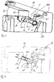
- Figur 1
- eine dreidimensionale erste Seitenansicht einer Haltevorrichtung,
- Figur 2
- eine dreidimensionale zweite Seitenansicht der in
Figur 1 gezeigten Haltevorrichtung, - Figur 3
- eine Seitenansicht der in
Figur 1 gezeigten Haltevorrichtung mit geöffnetem Deckel, - Figur 4
- eine teilweise geschnittene Seitenansicht der in
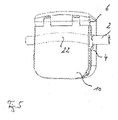
Figur 1 gezeigten Haltevorrichtung und - Figur 5
- eine dreidimensionale Draufsicht auf die in
Figur 1 gezeigte Haltevorrichtung. - Die in
Figur 1 gezeigte Haltevorrichtung 1 ist an einem Schlauch 2 angeklemmt, um mit einem in der Haltevorrichtung 1 angeordneten Sensor 3 (vgl.Figur 4 ) ein im Schlauch 2 geführtes Medium zu untersuchen. Der Schlauch 2 wird in der Schlauchaufnahme 4 mit dem Stempel 5 gehalten. Der Stempel 5 ist um den Anlenkpunkt 6 schwenkbar an der Schlauchaufnahme 4 befestigt und um diesen Anlenkpunkt 6 leicht gebogen ausgebildet. - Dies ermöglicht es, den Schlauch 2 in die Schlauchaufnahme 4 zu legen und mittels des Stempels 5 in die Schlauchaufnahme und in die in
Figur 1 gezeigte definierte Position relativ zum Sensor 3 zu drücken. - Um den Schlauch 2 vorsichtig in die Schlauchaufnahme 4 drücken zu können, hat der Stempel 5 eine abgerundete Anlagefläche 7. Die abgerundete Anlagefläche 8 der Schlauchaufnahme 4 dient dazu, den Schlauch sicher in der Schlauchaufnahme 4 zu halten.
- Dadurch bilden der Stempel 5 und die Schlauchaufnahme 4 einen Rohrbereich 9, in dem der Schlauch 2 gehalten wird. Die Anlagefläche 7 des Stempels 5 umgreift den Schlauch auf einem Kreissegment von weniger als 180° und vorzugsweise zwischen 45° und 80°, während die abgerundete Fläche 8 der Schlauchaufnahme 4 den Schlauch auf einem Kreissegment von mindestens 150° und vorzugsweise mehr als 170° umfasst. Eine spezielle Ausführungsform sieht eine Anlagefläche 8 vor, die den Schlauch um mehr als 180° umfassen kann, sodass der Schlauch gegen einen kleinen Widerstand in die Schlauchaufnahme gedrückt wird.
- Der Stempel 5 ist an einem Deckel 10 angeordnet, der über den Anlenkpunkt 6 an der Schlauchaufnahme 4 befestigt ist. Dieser Deckel 10 hat eine Unterseite 11, die an einer Oberseite 12 der Schlauchaufnahme 4 anliegt, wenn der Stempel 5 den Schlauch 2 in die definierte Position 13 relativ zum Sensor 3 gedrückt hat. Eine Rasteinrichtung (nicht gezeigt) führt dazu, dass beim Schließen des Deckels 10 fühlbar ist, wenn die definierte Position 13 des Schlauches 2 relativ zur Schlauchaufnahme 4 erreicht ist. In dieser Position kann der Deckel 10 mittels einer Verriegelungseinrichtung (nicht gezeigt) mit der Schlauchaufnahme 4 derart verbunden werden, dass der Stempel 5 nicht mehr um den Anlenkpunkt 6 geschwenkt werden kann. Die Verriegelungseinrichtung kann die Rasteinrichtung derart blockieren, dass eine Öffnung nur dann möglich ist, wenn eine Sicherungseinrichtung vorher die Verriegelung und damit die Verrastung freigegeben hat. Dabei sollte vermieden werden, dass der Deckel versehentlich geöffnet wird.
- Die Verriegelungseinrichtung kann mit der Rasteinrichtung kombiniert werden, indem der Deckel beim Verriegeln in der Schlauchaufnahme einrastet oder die Schlauchaufnahme mit dem Deckel rastend verriegelt wird.
- In den
Figuren 3 und 4 ist der Sender 14 gezeigt, der dem Sensor 3 gegenüberliegend angeordnet ist. Dieser Sender 14 ist im Ausführungsbeispiel eine Laserlichtquelle, die einen Strahlengang 15 erzeugt, der zwischen der Lichtquelle 16 und dem Schlauch 2 in einem Lichtkanal 17 geführt ist. Dieser Lichtkanal 17 ist im Ausführungsbeispiel etwa 10 mm lang und in der Praxis ergibt sich die Länge in Abhängigkeit vom Schlauchdurchmesser, um den Strahlengang 15 der Lichtquelle 16 zu bündeln und ein Austreten von Streulicht zu vermeiden. - Das Austreten von direktem und indirektem Licht aus der Schlauchaufnahme 4 wird auch durch den gebogenen Einführkanal 18 minimiert, indem der gebogene Stempel 5 geführt ist. Beim Öffnen und Schließen des Deckels 10 bildet der Stempel 5 einen Sichtschutz 19, der den Blick in die Schlauchaufnahme 4 verhindert.
- Beim Öffnen des Deckels 10 entsteht zwischen Deckel 10 und Schlauchaufnahme 4 ein Öffnungswinkel, der sich im Wesentlichen zum Anlenkpunkt 6 verjüngt. Der Strahlengang 15 ist im Wesentlichen parallel zu diesem Öffnungswinkel geführt, sodass die Lichtquelle 16 das Licht zur Seite der Schlauchaufnahme 4 richtet, an der der Anlenkpunkt 6 angeordnet ist.
- Dadurch wird erreicht, dass ein Blick in Richtung der Verjüngung des Winkels 20 etwa gleichgerichtet mit dem Strahlengang 15 des Lichtes ist, wodurch vermieden wird, dass direkte Lichtstrahlen aus der Haltevorrichtung zum Betrachter hin entweichen.
- Streustrahlung wird insbesondere dadurch vermieden, dass der Deckel 10 und der Stempel 5 eine lichtabsorbierende Schicht 21 aufweisen.
- Da angestrebt ist, dass der Stempel 5 den Schlauch 2 möglichst wenig verformt, liegt der Schlauch 2 in einer Rinne 22, die sich senkrecht zur Bildebene der Abbildung in
Figur 4 erstreckt. Diese Rinne führt am Sender 14 und am Sensor 3 entlang, womit ein in die Rinne 22 eingelegter Schlauch zwischen dem Sender 14 und dem Sensor 3 angeordnet ist. Diese Rinne 22 kann auf einer senkrecht zur Bildebene verlaufenden Achse gebogen sein, um ein Verrutschen der Haltevorrichtung 1 relativ zum Schlauch 2 und ein Austreten von Streustrahlung aus der Vorrichtung zu verhindern. - Ein Stempeldetektor 23 an der Schlauchaufnahme 4 dient der Überwachung der Position des Stempels 5 im Einführkanal 18, damit der Sender 14 und vorzugsweise die Lichtquelle 16 erst eingeschaltet werden können, wenn der Deckel 10 und damit auch der Stempel 5 in der geschlossenen Position den Einführkanal 18 verschließen.
- Mehrere Schlauchdetektoren 24, 25 dienen der Überwachung der Position des Schlauchs 2. Dadurch kann vermieden werden, dass der Sender 14 und vorzugsweise die Lichtquelle 16 eingeschaltet werden, wenn kein Schlauch 2 eingelegt ist oder der Schlauch 2 nicht ordnungsgemäß eingelegt ist.
- Eine LED zeigt als Statusanzeiger 26 den Zustand der Haltevorrichtung. Diese LED kann beispielsweise grün leuchten, wenn der Schlauch ordnungsgemäß eingelegt ist und der Deckel 10 eingerastet ist. Sofern ein Detektor ein negatives Signal meldet, ist die Anzeige des Statusindikators 26 rot.
- Um den mittels des Sensors 3 ermittelten Wert optimal auswerten zu können, ist ein Temperatursensor 27 in der Nähe des Schlauches 2 angeordnet, der die Temperatur des Schlauches und/oder die Temperatur des im Schlauch geführten Mediums misst. Dafür ist im Ausführungsbeispiel der Temperatursensor 27 von der Schlauchaufnahme 4 thermisch entkoppelt.
- Um die Reparatur der Haltevorrichtung zu erleichtern, weist die Schlauchaufnahme 4 eine Aufnahme 28 auf, in die der Sender 14 eingesetzt werden kann, und eine weitere Aufnahme 29, in der der Sensor 3 geschützt angeordnet ist.
Claims (12)
- Haltevorrichtung (1) für einen Schlauch (2), die einen Sensor (3), eine Schlauchaufnahme (4), einem Einführkanal (18) und einen Stempel (5) aufweist, wobei der Stempel (5) beweglich ist, um den Schlauch (2) in der Schlauchaufnahme (4) zu halten und eine Entnahme des Schlauches (2) aus der Schlauchaufnahme (4) zu ermöglichen, wobei die Haltevorrichtung eine Lichtquelle (16) als optischen oder optoakustischen Sender aufweist, dadurch gekennzeichnet dass die Lichtquelle derart angeordnet ist, dass der direkte Strahlengang (15) des Lichts, auch wenn der Stempel (5) nicht im Einführkanal angeordnet ist, nicht durch den Einführkanal (1) aus der Haltevorrichtung (1) dringt, wobei der Stempel (5) um einen Anlenkpunkt (6) an der Schlauchaufnahme (4) gebogen ist und der Einführkanal (18) gebogen ist und eine Bewegung des Stempels (5) den Schlauch (2) in die Schlauchaufnahme (4) und in eine definierte Position (13) relativ zum Sensor (3) so drückt, dass durch die Ausbildung des gebogenen Stempels in Verbindung mit dem gebogenen Einführkanal der Schlauch derart in der Haltevorrichtung angeordnet werden kann, dass bei einem Bestrahlen des Schlauches durch eine Lichtquelle direkte Strahlung nur auf den Schlauch trifft.
- Haltevorrichtung nach Anspruch 1, dadurch gekennzeichnet, dass der Stempel (5) eine abgerundete Anlagefläche (7) für den Schlauch (2) aufweist.
- Haltevorrichtung nach einem der vorhergehenden Ansprüche, dadurch gekennzeichnet, dass die Schlauchaufnahme (4) eine abgerundete Anlagefläche (8) für den Schlauch (2) aufweist.
- Haltevorrichtung nach einem der vorhergehenden Ansprüche, dadurch gekennzeichnet, dass Stempel (5) und Schlauchaufnahme (4) einen Rohrbereich (9) bilden, um den Schlauch (2) einzuklemmen und zu halten.
- Haltevorrichtung nach einem der vorhergehenden Ansprüche, dadurch gekennzeichnet, dass sie einen Sender (14) aufweist, der dem Sensor (3) gegenüberliegend angeordnet ist.
- Haltevorrichtung nach einem der vorhergehenden Ansprüche, dadurch gekennzeichnet, dass zwischen der Lichtquelle (16) und der Schlauchaufnahme (4) ein Lichtkanal (17) angeordnet ist.
- Haltevorrichtung nach Anspruch 6, dadurch gekennzeichnet, dass der Lichtkanal (17) länger als 5 mm ist.
- Haltevorrichtung nach einem der vorhergehenden Ansprüche, dadurch gekennzeichnet, dass der Stempel (5) an einem an der Schlauchaufnahme (4) schwenkbar befestigten Deckel (10) angeordnet ist.
- Haltevorrichtung nach Anspruch 8, dadurch gekennzeichnet, dass der Deckel (10) rastend in einer definierten, insbesondere geschlossenen, Position anordenbar ist.
- Haltevorrichtung nach einem der vorhergehenden Ansprüche, dadurch gekennzeichnet, dass der Stempel (5), die Schlauchaufnahme oder der Einführkanal eine lichtabsorbierende Schicht (21) aufweist.
- Haltevorrichtung nach einem der vorhergehenden Ansprüche, dadurch gekennzeichnet, dass die Schlauchaufnahme (4) eine gekrümmte Rinne (22) aufweist, um einen gebogenen Schlauch (2) einzulegen.
- Haltevorrichtung nach einem der vorhergehenden Ansprüche, dadurch gekennzeichnet, dass sie einen Stempeldetektor (23) zur Überwachung der Position des Stempels (5) aufweist.
Applications Claiming Priority (2)
| Application Number | Priority Date | Filing Date | Title |
|---|---|---|---|
| DE102015011065 | 2015-08-27 | ||
| DE102015015587.3A DE102015015587A1 (de) | 2015-08-27 | 2015-12-04 | Haltevorrichtung für einen Schlauch |
Publications (2)
| Publication Number | Publication Date |
|---|---|
| EP3135197A1 EP3135197A1 (de) | 2017-03-01 |
| EP3135197B1 true EP3135197B1 (de) | 2022-06-15 |
Family
ID=56925944
Family Applications (1)
| Application Number | Title | Priority Date | Filing Date |
|---|---|---|---|
| EP16001873.5A Active EP3135197B1 (de) | 2015-08-27 | 2016-08-26 | Haltevorrichtung für einen schlauch |
Country Status (2)
| Country | Link |
|---|---|
| EP (1) | EP3135197B1 (de) |
| DE (1) | DE102015015587A1 (de) |
Families Citing this family (1)
| Publication number | Priority date | Publication date | Assignee | Title |
|---|---|---|---|---|
| US11493441B2 (en) * | 2019-01-15 | 2022-11-08 | Wyatt Technology Corporation | Flow cell, read head, and skid attachment |
Family Cites Families (12)
| Publication number | Priority date | Publication date | Assignee | Title |
|---|---|---|---|---|
| US4136818A (en) * | 1977-10-25 | 1979-01-30 | Union Carbide Corporation | Light-shielding tube holder for use with blood washing apparatus |
| JPS5551777U (de) * | 1978-10-02 | 1980-04-05 | ||
| DE3344632A1 (de) * | 1983-12-09 | 1985-06-20 | Siemens AG, 1000 Berlin und 8000 München | Vorrichtung zur registrierung der tropfen in einem infusionsgeraet |
| US4764166A (en) * | 1987-08-17 | 1988-08-16 | Fisher Scientific Company | Ultrasonic air-in-line detector |
| DE3815643A1 (de) * | 1988-05-07 | 1989-11-30 | Biotest Pharma Gmbh | Vorrichtung zur trennung von komponenten einer fluessigkeit, insbesondere von gesamtblut |
| US5463906A (en) | 1994-01-24 | 1995-11-07 | Triton Technology, Inc. | Interchangeable disposable acoustic for use with an ultrasonic flowmeter, particularly during extracorporeal measurement of blood flow |
| US6144444A (en) * | 1998-11-06 | 2000-11-07 | Medtronic Avecor Cardiovascular, Inc. | Apparatus and method to determine blood parameters |
| ITMI20090926A1 (it) * | 2009-05-26 | 2010-11-27 | Datamed Srl | Apparato e metodo per misure spettrofotometriche di parametri del sangue. |
| JP5439138B2 (ja) * | 2009-11-27 | 2014-03-12 | 日機装株式会社 | 血液浄化装置用チューブ把持装置及びそれを備えた血液浄化装置 |
| JP4878653B1 (ja) | 2011-01-28 | 2012-02-15 | 株式会社アツデン | 超音波流量測定装置 |
| US8714030B1 (en) * | 2011-09-10 | 2014-05-06 | Strain Measurement Devices, Inc. | Non-invasive tranducers for ultrasonic transit time flow meters |
| DE102012104461A1 (de) * | 2012-05-23 | 2013-12-12 | B. Braun Avitum Ag | Medizinisches Gerät zur extrakorporalen Blutbehandlung mit mehreren Sensoreinheiten |
-
2015
- 2015-12-04 DE DE102015015587.3A patent/DE102015015587A1/de active Pending
-
2016
- 2016-08-26 EP EP16001873.5A patent/EP3135197B1/de active Active
Also Published As
| Publication number | Publication date |
|---|---|
| DE102015015587A1 (de) | 2017-03-02 |
| EP3135197A1 (de) | 2017-03-01 |
Similar Documents
| Publication | Publication Date | Title |
|---|---|---|
| DE3935083C2 (de) | ||
| DE10204714B4 (de) | Ultraschall-Durchflussmesser | |
| DE69531989T2 (de) | Verfahren und apparat zum prüfen von ölförderanlagenrohrverbindungen mit gewinde | |
| KR101255796B1 (ko) | 집속 레이저 빔 측정 장치 | |
| DE102009014463A1 (de) | Vorrichtung und Verfahren zum Messen der Distanz zum Trommelfell | |
| DE19827343A1 (de) | Gerät zur Durchführung von Messungen im Ohr | |
| EP0632259A2 (de) | Vorrichtung zur Feststellung von Undichtigkeiten an Bauteilen | |
| EP0756703A1 (de) | Vorrichtung zur messung der lichtstreuung an partikeln | |
| EP0025564A2 (de) | Optische Vorrichtung zum Messen geringer Druckdifferenzen mittels Lichtintensitätsänderung | |
| DE102014222880A1 (de) | Adapter für die Endoskopie | |
| DE102007021182A1 (de) | Lokalisationseinheit für eine chirurgische Röntgendiagnostikeinrichtung mit Sterilabdeckfolie | |
| EP1826556A2 (de) | Prüfeinrichtung | |
| DE4446760C2 (de) | Vorrichtung zum Messen von Verformungen eines Gegenstandes | |
| WO2018077731A1 (de) | Sterile abdeckung für ein optisches gerät | |
| EP2930544A1 (de) | Umlenkprisma und Messanordnung | |
| EP3135197A1 (de) | Haltevorrichtung für einen schlauch | |
| DE10358647B4 (de) | Sensor zur Transmissionsmessung | |
| DE19545383A1 (de) | Verfahren zur Ortung eines Lecks an einem Hausanschlußrohr eines Trinkwasser-Versorgungsnetzes und Anordnung zur Leckortung unter Anwendung des Verfahrens | |
| DE19650992C2 (de) | Verfahren und Vorrichtung zur Bestimmung von mechanischen Eigenschaften elastischer Materialien | |
| DE102021107115A1 (de) | Vorrichtung zur Untersuchung einer Oberfläche eines Bauteils | |
| DE2139865B2 (de) | Fuellstandsanzeiger oder zustandsdetektor mit einem durch eine trennwand hindurchgefuehrten, im wesentlichen geraden lichtleiterstab | |
| EP1881319B1 (de) | Vorrichtung und Verfahren zur Messung der Lichtstreuung | |
| CN212160147U (zh) | 一种准直器及其保护管 | |
| DE102004025588A1 (de) | Dosierspitzenaufnehmer zur Aufnahme einer Dosierspitze | |
| DE102010013472A1 (de) | Nahtüberwachungs-Vorrichtung |
Legal Events
| Date | Code | Title | Description |
|---|---|---|---|
| PUAI | Public reference made under article 153(3) epc to a published international application that has entered the european phase |
Free format text: ORIGINAL CODE: 0009012 |
|
| STAA | Information on the status of an ep patent application or granted ep patent |
Free format text: STATUS: THE APPLICATION HAS BEEN PUBLISHED |
|
| AK | Designated contracting states |
Kind code of ref document: A1 Designated state(s): AL AT BE BG CH CY CZ DE DK EE ES FI FR GB GR HR HU IE IS IT LI LT LU LV MC MK MT NL NO PL PT RO RS SE SI SK SM TR |
|
| AX | Request for extension of the european patent |
Extension state: BA ME |
|
| STAA | Information on the status of an ep patent application or granted ep patent |
Free format text: STATUS: REQUEST FOR EXAMINATION WAS MADE |
|
| 17P | Request for examination filed |
Effective date: 20170704 |
|
| RBV | Designated contracting states (corrected) |
Designated state(s): AL AT BE BG CH CY CZ DE DK EE ES FI FR GB GR HR HU IE IS IT LI LT LU LV MC MK MT NL NO PL PT RO RS SE SI SK SM TR |
|
| STAA | Information on the status of an ep patent application or granted ep patent |
Free format text: STATUS: EXAMINATION IS IN PROGRESS |
|
| 17Q | First examination report despatched |
Effective date: 20210518 |
|
| REG | Reference to a national code |
Ref country code: DE Ref legal event code: R079 Ref document number: 502016014956 Country of ref document: DE Free format text: PREVIOUS MAIN CLASS: A61B0005145500 Ipc: G01N0021050000 |
|
| GRAP | Despatch of communication of intention to grant a patent |
Free format text: ORIGINAL CODE: EPIDOSNIGR1 |
|
| STAA | Information on the status of an ep patent application or granted ep patent |
Free format text: STATUS: GRANT OF PATENT IS INTENDED |
|
| RIC1 | Information provided on ipc code assigned before grant |
Ipc: G01N 21/53 20060101ALI20220112BHEP Ipc: G01F 1/661 20220101ALI20220112BHEP Ipc: G01N 21/05 20060101AFI20220112BHEP |
|
| INTG | Intention to grant announced |
Effective date: 20220203 |
|
| RIN1 | Information on inventor provided before grant (corrected) |
Inventor name: BURKHARD, MANFRED Inventor name: BOBER, MACIEJ Inventor name: HUBER, ELMAR |
|
| GRAS | Grant fee paid |
Free format text: ORIGINAL CODE: EPIDOSNIGR3 |
|
| GRAA | (expected) grant |
Free format text: ORIGINAL CODE: 0009210 |
|
| STAA | Information on the status of an ep patent application or granted ep patent |
Free format text: STATUS: THE PATENT HAS BEEN GRANTED |
|
| AK | Designated contracting states |
Kind code of ref document: B1 Designated state(s): AL AT BE BG CH CY CZ DE DK EE ES FI FR GB GR HR HU IE IS IT LI LT LU LV MC MK MT NL NO PL PT RO RS SE SI SK SM TR |
|
| REG | Reference to a national code |
Ref country code: CH Ref legal event code: EP Ref country code: GB Ref legal event code: FG4D Free format text: NOT ENGLISH |
|
| REG | Reference to a national code |
Ref country code: IE Ref legal event code: FG4D Free format text: LANGUAGE OF EP DOCUMENT: GERMAN |
|
| REG | Reference to a national code |
Ref country code: DE Ref legal event code: R096 Ref document number: 502016014956 Country of ref document: DE |
|
| REG | Reference to a national code |
Ref country code: AT Ref legal event code: REF Ref document number: 1498666 Country of ref document: AT Kind code of ref document: T Effective date: 20220715 |
|
| REG | Reference to a national code |
Ref country code: LT Ref legal event code: MG9D |
|
| REG | Reference to a national code |
Ref country code: NL Ref legal event code: MP Effective date: 20220615 |
|
| PG25 | Lapsed in a contracting state [announced via postgrant information from national office to epo] |
Ref country code: SE Free format text: LAPSE BECAUSE OF FAILURE TO SUBMIT A TRANSLATION OF THE DESCRIPTION OR TO PAY THE FEE WITHIN THE PRESCRIBED TIME-LIMIT Effective date: 20220615 Ref country code: NO Free format text: LAPSE BECAUSE OF FAILURE TO SUBMIT A TRANSLATION OF THE DESCRIPTION OR TO PAY THE FEE WITHIN THE PRESCRIBED TIME-LIMIT Effective date: 20220915 Ref country code: LT Free format text: LAPSE BECAUSE OF FAILURE TO SUBMIT A TRANSLATION OF THE DESCRIPTION OR TO PAY THE FEE WITHIN THE PRESCRIBED TIME-LIMIT Effective date: 20220615 Ref country code: HR Free format text: LAPSE BECAUSE OF FAILURE TO SUBMIT A TRANSLATION OF THE DESCRIPTION OR TO PAY THE FEE WITHIN THE PRESCRIBED TIME-LIMIT Effective date: 20220615 Ref country code: GR Free format text: LAPSE BECAUSE OF FAILURE TO SUBMIT A TRANSLATION OF THE DESCRIPTION OR TO PAY THE FEE WITHIN THE PRESCRIBED TIME-LIMIT Effective date: 20220916 Ref country code: FI Free format text: LAPSE BECAUSE OF FAILURE TO SUBMIT A TRANSLATION OF THE DESCRIPTION OR TO PAY THE FEE WITHIN THE PRESCRIBED TIME-LIMIT Effective date: 20220615 Ref country code: BG Free format text: LAPSE BECAUSE OF FAILURE TO SUBMIT A TRANSLATION OF THE DESCRIPTION OR TO PAY THE FEE WITHIN THE PRESCRIBED TIME-LIMIT Effective date: 20220915 |
|
| PG25 | Lapsed in a contracting state [announced via postgrant information from national office to epo] |
Ref country code: RS Free format text: LAPSE BECAUSE OF FAILURE TO SUBMIT A TRANSLATION OF THE DESCRIPTION OR TO PAY THE FEE WITHIN THE PRESCRIBED TIME-LIMIT Effective date: 20220615 Ref country code: LV Free format text: LAPSE BECAUSE OF FAILURE TO SUBMIT A TRANSLATION OF THE DESCRIPTION OR TO PAY THE FEE WITHIN THE PRESCRIBED TIME-LIMIT Effective date: 20220615 |
|
| PG25 | Lapsed in a contracting state [announced via postgrant information from national office to epo] |
Ref country code: NL Free format text: LAPSE BECAUSE OF FAILURE TO SUBMIT A TRANSLATION OF THE DESCRIPTION OR TO PAY THE FEE WITHIN THE PRESCRIBED TIME-LIMIT Effective date: 20220615 |
|
| PG25 | Lapsed in a contracting state [announced via postgrant information from national office to epo] |
Ref country code: SM Free format text: LAPSE BECAUSE OF FAILURE TO SUBMIT A TRANSLATION OF THE DESCRIPTION OR TO PAY THE FEE WITHIN THE PRESCRIBED TIME-LIMIT Effective date: 20220615 Ref country code: SK Free format text: LAPSE BECAUSE OF FAILURE TO SUBMIT A TRANSLATION OF THE DESCRIPTION OR TO PAY THE FEE WITHIN THE PRESCRIBED TIME-LIMIT Effective date: 20220615 Ref country code: RO Free format text: LAPSE BECAUSE OF FAILURE TO SUBMIT A TRANSLATION OF THE DESCRIPTION OR TO PAY THE FEE WITHIN THE PRESCRIBED TIME-LIMIT Effective date: 20220615 Ref country code: PT Free format text: LAPSE BECAUSE OF FAILURE TO SUBMIT A TRANSLATION OF THE DESCRIPTION OR TO PAY THE FEE WITHIN THE PRESCRIBED TIME-LIMIT Effective date: 20221017 Ref country code: ES Free format text: LAPSE BECAUSE OF FAILURE TO SUBMIT A TRANSLATION OF THE DESCRIPTION OR TO PAY THE FEE WITHIN THE PRESCRIBED TIME-LIMIT Effective date: 20220615 Ref country code: EE Free format text: LAPSE BECAUSE OF FAILURE TO SUBMIT A TRANSLATION OF THE DESCRIPTION OR TO PAY THE FEE WITHIN THE PRESCRIBED TIME-LIMIT Effective date: 20220615 Ref country code: CZ Free format text: LAPSE BECAUSE OF FAILURE TO SUBMIT A TRANSLATION OF THE DESCRIPTION OR TO PAY THE FEE WITHIN THE PRESCRIBED TIME-LIMIT Effective date: 20220615 |
|
| PG25 | Lapsed in a contracting state [announced via postgrant information from national office to epo] |
Ref country code: PL Free format text: LAPSE BECAUSE OF FAILURE TO SUBMIT A TRANSLATION OF THE DESCRIPTION OR TO PAY THE FEE WITHIN THE PRESCRIBED TIME-LIMIT Effective date: 20220615 Ref country code: IS Free format text: LAPSE BECAUSE OF FAILURE TO SUBMIT A TRANSLATION OF THE DESCRIPTION OR TO PAY THE FEE WITHIN THE PRESCRIBED TIME-LIMIT Effective date: 20221015 |
|
| REG | Reference to a national code |
Ref country code: DE Ref legal event code: R097 Ref document number: 502016014956 Country of ref document: DE |
|
| PG25 | Lapsed in a contracting state [announced via postgrant information from national office to epo] |
Ref country code: MC Free format text: LAPSE BECAUSE OF FAILURE TO SUBMIT A TRANSLATION OF THE DESCRIPTION OR TO PAY THE FEE WITHIN THE PRESCRIBED TIME-LIMIT Effective date: 20220615 Ref country code: AL Free format text: LAPSE BECAUSE OF FAILURE TO SUBMIT A TRANSLATION OF THE DESCRIPTION OR TO PAY THE FEE WITHIN THE PRESCRIBED TIME-LIMIT Effective date: 20220615 |
|
| REG | Reference to a national code |
Ref country code: CH Ref legal event code: PL |
|
| PLBE | No opposition filed within time limit |
Free format text: ORIGINAL CODE: 0009261 |
|
| STAA | Information on the status of an ep patent application or granted ep patent |
Free format text: STATUS: NO OPPOSITION FILED WITHIN TIME LIMIT |
|
| PG25 | Lapsed in a contracting state [announced via postgrant information from national office to epo] |
Ref country code: LU Free format text: LAPSE BECAUSE OF NON-PAYMENT OF DUE FEES Effective date: 20220826 Ref country code: LI Free format text: LAPSE BECAUSE OF NON-PAYMENT OF DUE FEES Effective date: 20220831 Ref country code: DK Free format text: LAPSE BECAUSE OF FAILURE TO SUBMIT A TRANSLATION OF THE DESCRIPTION OR TO PAY THE FEE WITHIN THE PRESCRIBED TIME-LIMIT Effective date: 20220615 Ref country code: CH Free format text: LAPSE BECAUSE OF NON-PAYMENT OF DUE FEES Effective date: 20220831 |
|
| REG | Reference to a national code |
Ref country code: BE Ref legal event code: MM Effective date: 20220831 |
|
| 26N | No opposition filed |
Effective date: 20230316 |
|
| GBPC | Gb: european patent ceased through non-payment of renewal fee |
Effective date: 20220915 |
|
| PG25 | Lapsed in a contracting state [announced via postgrant information from national office to epo] |
Ref country code: SI Free format text: LAPSE BECAUSE OF FAILURE TO SUBMIT A TRANSLATION OF THE DESCRIPTION OR TO PAY THE FEE WITHIN THE PRESCRIBED TIME-LIMIT Effective date: 20220615 |
|
| PG25 | Lapsed in a contracting state [announced via postgrant information from national office to epo] |
Ref country code: IE Free format text: LAPSE BECAUSE OF NON-PAYMENT OF DUE FEES Effective date: 20220826 Ref country code: FR Free format text: LAPSE BECAUSE OF NON-PAYMENT OF DUE FEES Effective date: 20220831 |
|
| PG25 | Lapsed in a contracting state [announced via postgrant information from national office to epo] |
Ref country code: BE Free format text: LAPSE BECAUSE OF NON-PAYMENT OF DUE FEES Effective date: 20220831 |
|
| REG | Reference to a national code |
Ref country code: AT Ref legal event code: MM01 Ref document number: 1498666 Country of ref document: AT Kind code of ref document: T Effective date: 20220826 |
|
| PG25 | Lapsed in a contracting state [announced via postgrant information from national office to epo] |
Ref country code: GB Free format text: LAPSE BECAUSE OF NON-PAYMENT OF DUE FEES Effective date: 20220915 Ref country code: AT Free format text: LAPSE BECAUSE OF NON-PAYMENT OF DUE FEES Effective date: 20220826 |
|
| P01 | Opt-out of the competence of the unified patent court (upc) registered |
Effective date: 20231020 |
|
| PG25 | Lapsed in a contracting state [announced via postgrant information from national office to epo] |
Ref country code: IT Free format text: LAPSE BECAUSE OF FAILURE TO SUBMIT A TRANSLATION OF THE DESCRIPTION OR TO PAY THE FEE WITHIN THE PRESCRIBED TIME-LIMIT Effective date: 20220615 |
|
| REG | Reference to a national code |
Ref country code: DE Ref legal event code: R082 Ref document number: 502016014956 Country of ref document: DE Representative=s name: FISH & RICHARDSON P.C., DE |
|
| PG25 | Lapsed in a contracting state [announced via postgrant information from national office to epo] |
Ref country code: HU Free format text: LAPSE BECAUSE OF FAILURE TO SUBMIT A TRANSLATION OF THE DESCRIPTION OR TO PAY THE FEE WITHIN THE PRESCRIBED TIME-LIMIT; INVALID AB INITIO Effective date: 20160826 |
|
| PG25 | Lapsed in a contracting state [announced via postgrant information from national office to epo] |
Ref country code: CY Free format text: LAPSE BECAUSE OF FAILURE TO SUBMIT A TRANSLATION OF THE DESCRIPTION OR TO PAY THE FEE WITHIN THE PRESCRIBED TIME-LIMIT Effective date: 20220615 |
|
| PG25 | Lapsed in a contracting state [announced via postgrant information from national office to epo] |
Ref country code: MK Free format text: LAPSE BECAUSE OF FAILURE TO SUBMIT A TRANSLATION OF THE DESCRIPTION OR TO PAY THE FEE WITHIN THE PRESCRIBED TIME-LIMIT Effective date: 20220615 |
|
| PG25 | Lapsed in a contracting state [announced via postgrant information from national office to epo] |
Ref country code: MT Free format text: LAPSE BECAUSE OF FAILURE TO SUBMIT A TRANSLATION OF THE DESCRIPTION OR TO PAY THE FEE WITHIN THE PRESCRIBED TIME-LIMIT Effective date: 20220615 |
|
| PG25 | Lapsed in a contracting state [announced via postgrant information from national office to epo] |
Ref country code: BG Free format text: LAPSE BECAUSE OF FAILURE TO SUBMIT A TRANSLATION OF THE DESCRIPTION OR TO PAY THE FEE WITHIN THE PRESCRIBED TIME-LIMIT Effective date: 20220615 |
|
| PG25 | Lapsed in a contracting state [announced via postgrant information from national office to epo] |
Ref country code: BG Free format text: LAPSE BECAUSE OF FAILURE TO SUBMIT A TRANSLATION OF THE DESCRIPTION OR TO PAY THE FEE WITHIN THE PRESCRIBED TIME-LIMIT Effective date: 20220615 |
|
| PGFP | Annual fee paid to national office [announced via postgrant information from national office to epo] |
Ref country code: DE Payment date: 20250702 Year of fee payment: 10 |
|
| PG25 | Lapsed in a contracting state [announced via postgrant information from national office to epo] |
Ref country code: TR Free format text: LAPSE BECAUSE OF FAILURE TO SUBMIT A TRANSLATION OF THE DESCRIPTION OR TO PAY THE FEE WITHIN THE PRESCRIBED TIME-LIMIT Effective date: 20220615 |