EP3134770B1 - Anzeigevorrichtung mit simulation von reflexe und oder flimmern - Google Patents
Anzeigevorrichtung mit simulation von reflexe und oder flimmern Download PDFInfo
- Publication number
- EP3134770B1 EP3134770B1 EP15721151.7A EP15721151A EP3134770B1 EP 3134770 B1 EP3134770 B1 EP 3134770B1 EP 15721151 A EP15721151 A EP 15721151A EP 3134770 B1 EP3134770 B1 EP 3134770B1
- Authority
- EP
- European Patent Office
- Prior art keywords
- image
- reflective surface
- screen
- reflections
- medium
- Prior art date
- Legal status (The legal status is an assumption and is not a legal conclusion. Google has not performed a legal analysis and makes no representation as to the accuracy of the status listed.)
- Active
Links
Images


Classifications
-
- G—PHYSICS
- G03—PHOTOGRAPHY; CINEMATOGRAPHY; ANALOGOUS TECHNIQUES USING WAVES OTHER THAN OPTICAL WAVES; ELECTROGRAPHY; HOLOGRAPHY
- G03B—APPARATUS OR ARRANGEMENTS FOR TAKING PHOTOGRAPHS OR FOR PROJECTING OR VIEWING THEM; APPARATUS OR ARRANGEMENTS EMPLOYING ANALOGOUS TECHNIQUES USING WAVES OTHER THAN OPTICAL WAVES; ACCESSORIES THEREFOR
- G03B15/00—Special procedures for taking photographs; Apparatus therefor
- G03B15/08—Trick photography
- G03B15/12—Trick photography using mirrors
-
- G—PHYSICS
- G03—PHOTOGRAPHY; CINEMATOGRAPHY; ANALOGOUS TECHNIQUES USING WAVES OTHER THAN OPTICAL WAVES; ELECTROGRAPHY; HOLOGRAPHY
- G03B—APPARATUS OR ARRANGEMENTS FOR TAKING PHOTOGRAPHS OR FOR PROJECTING OR VIEWING THEM; APPARATUS OR ARRANGEMENTS EMPLOYING ANALOGOUS TECHNIQUES USING WAVES OTHER THAN OPTICAL WAVES; ACCESSORIES THEREFOR
- G03B21/00—Projectors or projection-type viewers; Accessories therefor
- G03B21/14—Details
- G03B21/26—Projecting separately subsidiary matter simultaneously with main image
-
- G—PHYSICS
- G03—PHOTOGRAPHY; CINEMATOGRAPHY; ANALOGOUS TECHNIQUES USING WAVES OTHER THAN OPTICAL WAVES; ELECTROGRAPHY; HOLOGRAPHY
- G03B—APPARATUS OR ARRANGEMENTS FOR TAKING PHOTOGRAPHS OR FOR PROJECTING OR VIEWING THEM; APPARATUS OR ARRANGEMENTS EMPLOYING ANALOGOUS TECHNIQUES USING WAVES OTHER THAN OPTICAL WAVES; ACCESSORIES THEREFOR
- G03B21/00—Projectors or projection-type viewers; Accessories therefor
- G03B21/54—Accessories
- G03B21/56—Projection screens
- G03B21/60—Projection screens characterised by the nature of the surface
Definitions
- the present invention belongs to the field of virtual reality and the virtual representation of objects.
- the invention relates to a device for displaying a virtual object comprising a virtual representation of the flickering of the object such that it can result from luminous reflections on the surface of the object or phenomena of diffraction or refraction of light rays in the object.
- the current software renders with great detail and realism the objects in computer graphics through the use of color, textures, shading, transparency and reflections.
- the realism obtained remains essentially that of a photograph which, on paper, renders a matte image and on a screen a luminous image, more or less contrasted according to the qualities of the screen which can be a screen diffusing the light when the projection is performed on a rear face of the screen and a screen having diffuse reflection properties to obtain optimal viewing angles when the image is projected on a front face of the screen.
- the images, photographic or synthetic, displayed on the screens are not able to restore the flicker, ie the unstable reflection, which is observed on an object when a ray of light is reflected on certain facets of an object or when it is diffracted by the matter of the object and that physical interactions act on the stability of light ray paths or their perceptions as when the observation point, the position of the light source or the position of the object is changed.
- a separation of the display means of the conventional image and the means of displaying complementary representations of the first are thus obtained, the latter being no longer constrained by the performance of the image display means and making it possible to put implement devices providing a high dynamic in the light performance and without compromising on the quality of the displayed images of the first image.
- the image diffusion system is configured to transmitting to the projector one or more synchronized images with one or more images transmitted on the screen. It is thus obtained a coherence in the space and time of the second image and the attributes that it comprises with the displayed image.
- the second image is a reflection and / or flicker image of a first image with which said second image is associated in the digital image delivery system.
- the display device then makes it possible to represent an image of graphic quality as high as desired and possible with effects of reflections and flickering having a brightness greater than the capabilities of the display screen and with a realistic rendering due to physical phenomena operated by the reflective surface.
- the digital image broadcasting system comprises means for generating a three-dimensional image of an object, a first image of which is transmitted to the screen, and comprises means for almost simultaneous generation of images. at least a second image representative of the reflections on the object represented by said first image.
- the display device further comprises means for making micro-displacements of the second image projected around a theoretical position of said second image, micro-displacements of an amplitude at most the same order of magnitude as the dimensions of the geometric patterns in relief of the reflecting surface.
- the projector is a video projector suitable for projecting second images or a laser beam scanning projector. It is thus possible to adapt the projection conditions of the second image according to an environment, a dimension of the projected image or the dynamics sought in the effects brought by the second picture.
- a support of the reflective surface is attached to or very close to the display face of the screen, with a rear face of said support of the reflective surface located on the screen side and a front face said support of the reflective surface located on the side of the projector, said support of the reflective surface appearing substantially transparent for light rays arriving on the back side and substantially reflecting for light rays arriving on the front face.
- the reflective surface advantageously has raised geometric patterns whose characteristic dimensions are such that the first image observed by transparency through the support of the reflecting surface is not deformed in a substantially perceptible manner for an observer located at a planned viewing distance, for example of the order of twice a diagonal of the screen.
- a planned viewing distance for example of the order of twice a diagonal of the screen.
- an inclined semi-transparent plate is located on an optical path between an observation window and the screen and arranged to return to the observation window light rays reflected by the reflecting surface so that a second image projected on the reflecting surface is optically superimposed on a first image displayed on the screen.
- the image displayed on the screen is seen through the support of the reflecting surface, avoiding possible perceptible distortions of the image, and thus eliminating the requirement of transparency of the image.
- support of the reflecting surface which allows to use for the support of the reflective surface technologies otherwise prohibited by the requirement of transparency.
- the geometric pattern or patterns in relief of the reflecting surface are random or pseudo random on at least a portion of said reflecting surface, and or the geometric pattern or patterns in relief of the reflecting surface are structured to form a repeating regular pattern on at least a portion of said reflective surface, and wherein the one or more raised geometric patterns of the reflecting surface are correlated to all or a portion of an object represented by the first image.
- the reflecting surface is superimposed on the entire image displayed by the screen or superimposed only on a portion of the image displayed on the screen.
- the relief of the geometric patterns on the side of the reflecting surface of the support of the reflecting surface is the result of an embossing of a film having a reflective surface, a shaping of a support for a reflective surface, a molding or a machining of a support of a reflective surface, a random dispersion of reflective flakes on the surface of a support, a random dispersion of flakes reflective in a transparent material of a support.
- the invention also relates to a method of visual simulation of reflections and flickering of an object presented in the form of a first image of said object displayed on a screen according to the rev. independent 14.
- a resulting image is thus obtained with reflections and flickers whose production is independent of the screen used to display the first image and which makes it possible to create impossible dynamic effects, to be obtained by means of the single screen, since it results from physical phenomena of different natures.
- the first image is derived from a photograph of the object presented and the second image is made by digital processing of the photograph of the object of which are identified surfaces and areas of reflection and flickers and or by image synthesis.
- the first image is a synthetic image of the object presented and in which the second image is a synthetic image of the areas of the object to include reflections and or flicker.
- the digital processing of the computer image and reflections and flickers can be performed jointly by common or synchronized calculation units, particularly in the case of dynamic images.
- the second image is a monochrome image of the areas of the object to be reflected and / or flickering or, in another embodiment, the second image is a polychrome image of the areas of the object to be comprised of reflections and or flickering, the colors being adapted to the colors of the desired reflections or flickers.
- the first image is an animated image and the second projected image is animated to be in correspondence with every moment with the first image displayed.
- animated objects are obtained in which the reflections and flickerings, modified at each image by the different conditions of each displayed image and of each projected image, produce a realistic rendering for an observer.
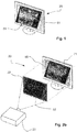
- the figure 1 represents a display terminal 20 according to the invention displaying an image 59.
- the image 59 is in the invention the result of an optical superposition, relying as much as needs on mechanical means, of a first digital image 50, which can be of synthesis or obtained by the photograph of a real object, and a second image 52 representative of reflections or flickering 51 of the image 59.
- the terminal is intended to be viewed by an observer of the image 59 and the terms and expressions used in the present description are, unless obvious or otherwise exact, to be considered in the common sense given to them in the field of the systems of image display.
- the reflections or flickers thus symbolized may be fixed or appear scintillating, that is to say relatively unstable in brightness to an observer, for example due to head movements even relatively imperceptible, while remaining substantially in one and the same location.
- object represented by the first image 50 may be fixed or appear scintillating, that is to say relatively unstable in brightness to an observer, for example due to head movements even relatively imperceptible, while remaining substantially in one and the same location.
- the reflections and flickering of the real object correspond to reflections of light sources or to the diffraction of light rays on edges of the object or to the refraction of light rays in transparent parts of the object. previewed.
- the figure 2a represents a display device 100 according to a first embodiment of the invention.
- said display terminal mainly comprises a screen 21 and a support 22 of a reflecting surface.
- the screen 21 is a conventional screen that can be of any type designed to display images with the light photons emerging or diffused by the screen.
- the screen 21 uses a principle of reflection of an image projected from one side of the screen where is also located an observer of the image.
- the image screen is an LCD technology screen in which the visible image results from the controlled transparency of colored dots, forming a matrix on a display face of the screen, and backlit by white light.
- the image screen 21 is chosen according to the desired display performance in terms of dimensions, resolution, color rendition, brightness, and contrast among the many available screen designs.
- the support 22 of the reflecting surface is for example a film which has the quality of appearing substantially transparent to a light arriving on a rear face of said reflecting film and appearing substantially reflecting and producing a specular reflection of a light arriving on a surface. front face of said reflective surface.
- the support 22 of the reflective surface therefore has characteristics similar in optical terms to those of a mirror without a tint, but will preferably be made with a sheet of a transparent polymer as a support, and light transmission coefficients will also be sought. high as possible for the light rays arriving on the rear face and reflection also as high as possible for light rays arriving on the front face, in the areas of the angles of incidence obtained due to the mechanical and optical assemblies of the device of display 100.
- the support 22 of the reflecting surface is fixed on the screen 21 with a rear face of the support affixed to all or part of the surface of said screen on which the first image 50 is displayed.
- the support 22 of the reflecting surface is, for example, an embossed film, in one embodiment in an irregular manner so as to avoid regular screening of the embossing.
- the embossing results in geometric patterns in relief on the reflecting face of the reflective surface of the film.
- An embossing of the film is for example obtained by crumpling a relatively rigid polymer sheet of said film and by flattening said sheet which keeps in memory the deformations undergone when it has been crumpled.
- the embossing of the film can also be achieved by stamping said reflecting film between a punch and a die, said punch and said die having surfaces whose reliefs reproduce the embossing pattern to be made on the reflecting film.
- any technique making it possible to produce a reflective film whose reflecting surface has facets with a random or pseudo-random distribution may be used provided that the reflective film can be produced with the desired dimensions and with the specular reflection characteristics enabling get the desired effect.
- the support of the reflective surface is also made of a transparent material which allows the observation of an image displayed on the screen 21 in front of which is placed the support of the reflecting surface.
- incident light rays 231 projected by the projector 23 are reflected by specular reflection in random directions as a function of the location on the reflective surface where they end, giving the reflected light rays 232.
- random or pseudo random directions as schematically represented on the figure 3 the detail of which the continuous lines represent incident light rays from a source and the discontinuous lines represent the reflected rays, which are oriented in directions according not only to the direction of the incident ray but also from the considered point of the surface of the reflective surface.
- the geometric patterns embossed on the reflective surface comprise, at least on a portion of the reflecting surface, a repeating regular pattern whose geometry and dimensions are chosen to reflect light by generating flickering effects. structured by said regular pattern, in the manner of some effect filters implemented in the field of photography, said repeating regular pattern being optionally superimposed on random geometric patterns.
- the geometric patterns in relief on the reflecting surface comprise, at least on a portion of the reflecting surface, a pattern whose geometry and dimensions are chosen to correspond to the shapes and surfaces of the object represented. by an image 50 to be displayed with the display device 100 so as to reflect the light selectively for the relevant areas of the image.
- said pattern is optionally superimposed on random geometric patterns and or regular.
- the projector 23 is arranged in the display device 100 with respect to the display terminal 20 for projecting images on the display surface of said terminal and therefore on the reflecting front face of the support 22 of the reflecting surface.
- the projector 23 is arranged so as not to disturb an observer of the images displayed on the terminal 20.
- an optical axis of said projector remains close to the viewing direction of the screen 21 so that the light power reflected by the reflecting surface is maximized in the direction of the observer.
- the projector 23 is fixed in a median plane of the screen 21 but shifted upwards or downwards with respect to the axis of the screen corresponding to a normal to the display surface coming from the center of the screen. 'screen.
- the corresponding corrections are set in the projector in view of its position.
- the corresponding corrections can also be made directly on the images that are transmitted by the system 24 to the projector by anamorphosis of said images.
- the digital image broadcasting system 24 may consist of any system configured to transmit and synchronize images in digital form to the terminal 20 on the one hand and to the projector 23 on the other hand.
- the digital image broadcasting system 24 incorporates a computing unit, for example a computer advantageously architected with graphic processors, programmed for image processing and manipulation.
- the images transmitted by the digital image broadcasting system can be fixed or animated.
- the digital image broadcasting system 24 may consist of image memories and a terminal for managing and selecting still or moving images, or, in one embodiment, comprising a synthesis image generator capable of producing real-time images based on commands, for example orientation, a virtual object.
- a particularity of the digital image broadcasting system 24 lies in the coupling of the first images 50 transmitted to be displayed synchronously on the screen 21 with second images 52 transmitted to be projected on the display screen 20 by the projector 23.
- At least one second image 52 is transmitted to the projector 23, the second image which is projected on the display screen 20 on which the luminous portions of the said second image, reflected by the reflecting surface, are observed in mainly specular reflection superimposed on the first image 50 displayed by the screen 21, observed by transparency on said screen because of the transparency of the support 22 of the reflecting surface, for form the image 59 observed.
- Each light ray coming from the projector 23 and corresponding to a point of a light portion of the second projected image is further reflected in a direction which is a function of the orientation in space of an osculating plane of the front face of the support 22 of the reflective surface at the location where the light ray considered reaches said reflective surface, as illustrated by the enlarged detail of the figure 3 .
- Due to the relief of the reflective surface, for example resulting from the embossing of the reflective film when this solution is used to form the reflecting surface, the orientation of the osculating planes at different points of said reflective surface and therefore the direction in which a ray of light incident is reflected is, to a certain extent, random and creates an instability that produces a flickering effect on localized bright spots.
- the second images 52 preferably consist of black images constellated with white or colored surfaces for which the projector 23 generates light beams which are reflected on the reflecting surface in more or less random directions, by example because of the embossing of the reflective film.
- a first fixed image 50 which is displayed on the screen 21 of the display terminal 20.
- Such a first image that is transmitted from a memory of On the screen 21 is for example an image of an object resulting from a photograph of the object or a synthetic image obtained from a virtual representation of the object.
- the first image 50 presents the desired attributes to be displayed with respect to contours, colors, contrasts, textures, shadings at least within the performance limits of which the selected screen 21 is capable.
- the image can have a high realism but the limits of the screens available in terms of brightness of isolated points limit the ability of rendering light reflections on the object.
- Each point of a light surface of the second image 52 corresponds in projection in the display device to a particular point or zone of the first image 50 on the screen 21 on which it is desired to create an effect of reflections or flicker.
- the incident light rays, emitted by the projector 23 and corresponding to the light spots of the second image 52, are reflected by specular reflection on arriving at the reflecting surface, and produce a light effect whose intensity can be much greater than the possibilities of the light. 21, since it is the effect of the direct reflection of the light of the projector rather than diffusion or diffuse reflection.
- the flickering effect is increased by the fact that all the movements of an observer relative to the display device 100 will have the effect of modifying the positions on the image of the reflections corresponding to incident light rays emitted by the projector reflected in the its direction of observation by the reflecting surface.
- a first image 50 is associated with several second images 52 which are projected successively, where appropriate with a fade-out of said second images, thus giving the object represented on the first image 50, although fixed. , a dynamic impression of brilliance and reflections.
- a single second image 52 is associated with a plurality of first images 50 which are displayed successively, thus giving the object shown, whose scintillating portions are fixed, a motion or context making it appear as much more realistic.
- a first animated image 50 is displayed on the screen 21.
- the first image can be animated in a predefined manner and in this case the digital image broadcasting system 24 displays a film corresponding to an established scenario.
- the image may be animated by an operator, who may be the observer of the first image 50, for example by a command acting on the digital image broadcasting system 24 to modify the first image, for example acting on a orientation of an object in the virtual space of the image.
- a first image is advantageously a three-dimensional synthetic image that is manipulated by the observer by a command such as a designation ball or a mouse.
- the digital image broadcasting system 24 transmits to the projector 23, at each moment, a second image 52 of reflections corresponding to the first image 50 transmitted to the screen 21.
- the reflection images are either pre-recorded to correspond to the film to be displayed for the images 50, or calculated in real time to correspond to the image 50 displayed.
- the manipulated object will be associated with a numerical model making it possible to determine the points of the object to produce reflections and scintillations according to the orientation of the object in an observer frame and according to the position of sources of illumination of the object.
- the digital image broadcasting system 24 synchronizes the first images 50 transmitted on the screen 21 with the second images 52 transmitted to the projector so that at any time a second projected image is coherent with a first displayed image.
- Such synchronization is provided by conventional means such as they are implemented for example in the projection of stereoscopic images.
- the first image 50 is an animated image obtained by cinematographic means, for example by means of a digital camera.
- the images provided by the camera are received by the digital image system 24 in which they are processed, or after being processed by a separate system, to identify the locations on which the effects of glare and flicker are to be produced. .
- the object filmed with the digital camera is itself subjected to an illumination adapted to bring out the light reflected and refracted naturally by the object.
- the images obtained with the digital camera are then processed to obtain images of the locations of the object emitting reflected or refracted light and to produce second images 52 isolated and synchronized with the first images from the film and on which were eventually eliminated , by digital means, the reflections.
- the first images 50 from the film of the real object and the second images 52 are then superimposed on the display terminal 20 of the device display 100 so as to render the display of the images of the real object with the effects of reflections and flickering appearing at the desired locations on the object taking into account the synchronization of the first and second images.
- the support 22 of the reflective surface although marked geometric patterns in relief, is virtually invisible and has no effect on the quality of observation of the first image 50 displayed on the screen 21 because of small heights the relief of the patterns, an order of magnitude of a millimeter or less, because it is applied directly to the surface of the screen 21, or at least very closely, and because said screen is preferably chosen to produce a contrasting and relatively bright image, while respecting the desired colorimetric characteristics.
- the projector 23 is a video projector which projects the second images 52 so as to ensure their overlapping with the first images 50 displayed on the screen 21 and to produce the effects of reflections and flickering at the desired locations for obtain the resulting image 59.
- a second image 52 is a black image, or at least a dark and neutral color, thus not transmitting the light of the projector, except at locations corresponding to transparent areas, colorless or colorless, corresponding to light rays of the projector to reach the desired locations on the display terminal 20.
- the projector 23 is an image projector using one or more laser beams whose scanning synchronized with the ignition and the extinction of the laser beams projects incident light rays on the display screen 20 at the desired locations to create the effects of reflections and flickering.
- the second images projected by the projector 23 on the reflecting surface are subject to displacement continuous following small movements more or less random around their theoretical positions, for example orbital movement, whose amplitude is of the same order of magnitude as the patterns of the reflective surface, for example resulting from an embossing of the reflective film.
- micro-displacements have the effect of increasing the flickering effect by inducing instability of the reflections on the reflective surface, and without the movement being clearly perceptible with respect to the first image 50.
- the second image 52 is a synthetic image produced by the digital image diffusion system 24 and the micro-displacements are applied individually and uncorrelated to different areas of the second image 52.
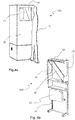
- FIGS. 4a and 4b illustrate a second embodiment of the invention.
- This second mode has the same elements as in the first mode but in a different arrangement to produce the superimposition of light reflections on a reflective surface in coincidence with desired locations on an image displayed by a screen 21.
- the support 22 of the reflecting surface is not fixed on or very close to the screen 21 but is separated from said screen while being optically superposed by a semi-transparent blade system 25 for example inclined at 45 ° in the illustrated embodiment.
- the screen 21 is in a substantially vertical position in a rear part of a support 30, in the axis of an observation window 26 through which an observer 31 is able to view it by direct vision through the semi-transparent blade 25.
- the first image 50 is not observed by transparency through the support 22 of the reflecting surface and therefore said medium does not have a transparency requirement.
- the support may in this case be opaque and have a reflective surface optimized to reflect specular reflection light rays with optimal performance, in practice close to the unit.
- the reflective surface is for example obtained by metallization of a previously formed surface in a polymeric material.
- the reflective surface is for example obtained by the embossing of a metal foil having a surface corresponding to a polished state.
- the superposition of the reflection effects and the observed image results as in the first embodiment of the synchronization in space, by the principle of optical superposition of the two images by means of the semi-transparent plate, and in the time of the image 50 of the object displayed on the screen 21 with that of the reflections 52 projected by the projector 23 on the reflecting surface.
- the invention also relates to a method, schematized on the figure 5 , for displaying on-screen images with effects of light reflections and or more or less intense flicker, that a conventional display screen is not able to render with a desired dynamic.
- a first image 50 of an object to be displayed is created.
- the said first image 50 of the object to be displayed is an image obtained by photography of a real object or by numerical synthesis of the object.
- the said first image 50 of the object to be displayed is a still image or an animated image.
- a second image 52 correlated with the first image 50, is created in which only the points and or surfaces of the first image 50 on which reflections and or flickerings must appear are represented in a contrasted manner against a background uniform.
- the uniform background is dark and the points corresponding to reflections are white or colored depending on the desired effect.
- the first and second steps, which precede a display step can be performed in any order or even simultaneously.
- the first image 50 is displayed on a screen 21 of a display terminal 20 whose display surface is in optical coincidence with a reflective surface a reflective surface having one or more geometric patterns in relief.
- a reflective surface a reflective surface having one or more geometric patterns in relief.
- the second image 52 is projected simultaneously, at least in terms of visual perception, onto the reflecting surface so that said second image representative of the desired flickers and reflections on the first image 50 coincides, in time and in space, on the said terminal with the said first image, to form a resultant image 59 including the effects of flickering and reflections.
- the display device 100 is particularly suitable for displaying images of objects whose realism is improved by the presence of reflections and flickering of the light illuminating these objects.
- the display device can also be used for the representation with increased realism of objects emitting a clean light but which can be perceived as relatively intense and scintillating as for example the light of the stars in a dark sky or the light emitted by a lighthouse or generally by a lamp.
- the invention finds application whenever objects naturally having reflections and flickering of light must be represented by images with maximum realism.
- Such conditions are found, for example, in technical situations for the analysis of phenomena, in didactical situations to present objects in realistic configurations and as close as possible visually as possible to a student population, in industrial situations to visualize at a project stage the effects of glare and flicker that will be achieved by a particular form of an object and to compare different options, in commercial situations to present to a buying public a rendering as realistic as possible of objects not available to be presented physically.
- the invention can also be implemented to draw an observer's attention to specific locations of an image by integrating reflections into the image in the form of bright spots, for example in stressful situations. and requiring a high concentration to attract significant attention from an operator without degrading the informative content of the image he has in front of him.
Landscapes
- Physics & Mathematics (AREA)
- General Physics & Mathematics (AREA)
- Overhead Projectors And Projection Screens (AREA)
- Projection Apparatus (AREA)
Claims (17)
- Vorrichtung zum Anzeigen (100) von Bildern (59), umfassend ein Visualisierungsgerät (20), von dem ein Bildschirm (21) funktionell an ein System zur Verbreitung von digitalen Bildern (24) angeschlossen ist, um ein erstes Bild (50) auf dem Bildschirm anzuzeigen, dadurch gekennzeichnet, dass sie umfasst:- einen Projektor (23), der funktionell an das System zur Verbreitung von digitalen Bildern (24) angeschlossen ist, um ein zweites Bild (52) auf eine im Wesentlichem gemäß einem Spiegelreflexionsmodus reflektierende Oberfläche zu projizieren, wobei die reflektierende Oberfläche ein oder mehrere erhabene geometrische Muster zeigt, sodass einfallende Lichtstrahlen abhängig von Reflexionspunktstellen auf der die einfallenden Strahlen reflektierenden Oberfläche in unterschiedliche Richtungen reflektiert werden; wobei das zweite Bild dem ersten Bild überlagerbar ist und auf einem einheitlichen Grund nur die Bereiche des im ersten Bild gezeigten Objekts darstellt, die Reflexe oder Funkeln umfassen sollen;- Mittel zur optischen Überlagerung des gesamten oder eines Teils des Bildschirms (21), die im transparenten Träger (22) der reflektierenden Oberfläche, welcher vor dem Bildschirm (21) platziert ist, oder in einer geneigten halbreflektierenden Scheibe (25) bestehen, welche zwischen dem Bildschirm und dem Träger der reflektierenden Oberfläche (22) platziert ist, sodass sich für einen Betrachter, der die Anzeigevorrichtung verwendet, ein auf die reflektierende Oberfläche projiziertes zweites Bild (52) einem auf dem Bildschirm (21) angezeigten ersten Bild (50) überlagert, um das betrachtete Bild (59) zu bilden.
- Anzeigevorrichtung nach Anspruch 1, wobei das System zur Verbreitung von Bildern (24) dafür konfiguriert ist, ein oder mehrere zweite Bilder (52) an den Projektor (23) zu übertragen, die mit einem ersten Bild (50), das an den Bildschirm (21) übertragen wird, synchronisiert sind.
- Anzeigevorrichtung nach einem der vorstehenden Ansprüche, wobei ein zweites Bild (52) ein Bild von Reflexen und/oder von Funkeln eines ersten Bildes (50) ist, dem das zweite Bild im System zur Verbreitung von digitalen Bildern (24) zugeordnet ist.
- Anzeigevorrichtung nach Anspruch 3, wobei das System zur Verbreitung von digitalen Bildern (24) Mittel zum Erzeugen eines dreidimensionalen Bildes eines Objekts umfasst, von dem ein erstes Bild (50) an den Bildschirm (21) übertragen wird, und Mittel zum quasi gleichzeitigen Erzeugen von mindestens einem zweiten Bild (52) umfasst, welches für die Reflexe auf einem vom ersten Bild dargestellten Objekt repräsentativ ist.
- Anzeigevorrichtung nach einem der vorstehenden Ansprüche, die Mittel zum Ausführen von Mikroverschiebungen des projizierten zweiten Bildes (52) um eine theoretische Position des zweiten Bildes herum umfasst, Mikroverschiebungen einer Amplitude von höchstens ein und derselben Größenordnung wie Abmessungen der erhabenen geometrischen Muster der reflektierenden Oberfläche.
- Anzeigevorrichtung nach einem der vorstehenden Ansprüche, wobei der Projektor (23) ein Videoprojektor, der zum Projizieren der zweiten Bilder (52) geeignet ist, oder ein Projektor mit Laserstrahlabtastung ist.
- Anzeigevorrichtung nach einem der vorstehenden Ansprüche, wobei ein Träger (22) der reflektierenden Oberfläche mit einer Rückfläche des Trägers der reflektierenden Oberfläche auf der Seite des Bildschirms (21) befindlich, und einer Vorderfläche des Trägers der reflektierenden Oberfläche auf der Seite des Projektors (23) befindlich auf oder sehr nahe an der Anzeigefläche des Bildschirms (21) befestigt ist, wobei der Träger der reflektierenden Oberfläche für Lichtstrahlen, die auf die Rückfläche treffen, im Wesentlichen transparent, und für Lichtstrahlen, die auf die Vorderfläche treffen, im Wesentlichen reflektierend erscheint.
- Anzeigevorrichtung nach Anspruch 7, wobei die reflektierende Oberfläche erhabene geometrische Muster zeigt, von denen charakteristische Abmessungen derart sind, dass das erste Bild (50), das durch Transparenz durch den Träger der reflektierenden Oberfläche hindurch betrachtet wird, für einen Betrachter, der sich in einem vorgesehenen Betrachtungsabstand befindet, zum Beispiel in der Größenordnung des Zweifachen einer Diagonale des Bildschirms (21), nicht in wesentlich wahrnehmbarer Weise verformt ist.
- Anzeigevorrichtung nach einem der Ansprüche 1 bis 6, die eine um 45° geneigte halbtransparente Scheibe (25) umfasst, welche sich in einem optischen Pfad zwischen einem Betrachtungsfenster (26) und dem Bildschirm (21) befindet und dafür eingerichtet ist, Lichtstrahlen, die von der reflektierenden Oberfläche reflektiert werden, zum Betrachtungsfenster hin zurückzulenken, sodass ein zweites Bild (52), das auf die reflektierende Oberfläche projiziert wird, sich optisch einem ersten Bild (50), das auf dem Bildschirm (21) angezeigt wird, überlagert.
- Anzeigevorrichtung nach einem der vorstehenden Ansprüche, wobei das oder die erhabenen geometrischen Muster der reflektierenden Oberfläche auf mindestens einem Teil der reflektierenden Oberfläche zufällig oder pseudozufällig sind.
- Anzeigevorrichtung nach einem der vorstehenden Ansprüche, wobei das oder die erhabenen geometrischen Muster der reflektierenden Oberfläche strukturiert sind, um auf mindestens einem Teil der reflektierenden Oberfläche ein sich regelmäßig wiederholendes Muster zu bilden.
- Anzeigevorrichtung nach einem der vorstehenden Ansprüche, wobei das oder die erhabenen geometrischen Muster der reflektierenden Oberfläche mit allen oder einem Teil der Formen eines vom ersten Bild (51) dargestellten Objekts korreliert sind.
- Anzeigevorrichtung nach einem der vorstehenden Ansprüche, wobei die Erhabenheit der geometrischen Muster auf der Seite der reflektierenden Fläche des Trägers (22) der reflektierenden Oberfläche das Ergebnis sind eines Prägens eines Films, der eine reflektierende Oberfläche zeigt, eines Bildens eines Trägers einer reflektierenden Oberfläche, eines Formens oder eines Zerspanens eines Trägers einer reflektierenden Oberfläche, einer zufälligen Verteilung von reflektierenden Pailletten an der Oberfläche eines Trägers, einer zufälligen Verteilung von reflektierenden Pailletten in einem transparenten Material eines Trägers.
- Verfahren zur visuellen Simulation von Reflexen und Funkeln eines Objekts, das in der Form eines ersten Bildes (50) des Objekts gezeigt wird, welches auf einem Bildschirm (21) angezeigt wird, dadurch gekennzeichnet, dass es die Schritte umfasst des:- Erzeugens eines zweiten Bildes (52), das dem ersten Bild (50) überlagerbar ist, wobei das zweite Bild auf einem einheitlichen Grund nur die Bereiche des Objekts darstellt, die Reflexe und/oder Funkeln umfassen sollen; und anschließend- des Projizierens des zweiten Bildes (52) auf eine im Wesentlichem gemäß einem Spiegelreflexionsmodus reflektierende Oberfläche, wobei die reflektierende Oberfläche ein oder mehrere erhabene geometrische Muster zeigt, sodass die einfallenden Lichtstrahlen abhängig von Reflexionspunktstellen auf der die einfallenden Strahlen reflektierenden Oberfläche in unterschiedliche Richtungen reflektiert werden;- des Platzierens des transparenten Trägers (22) der reflektierenden Oberfläche vor dem Bildschirm (21), oder des Platzierens einer geneigten halbreflektierenden Scheibe (25) zwischen dem Bildschirm und dem Träger der reflektierenden Oberfläche;- des optischen Überlagerns des auf die reflektierende Oberfläche projizierten zweiten Bildes (52) dem auf dem Bildschirm (21) angezeigten ersten Bild (50), um ein betrachtbares Bild (59) des Objekts zu bilden, das Reflex- und/oder Funkeleffekte beinhaltet.
- Verfahren nach Anspruch 14, wobei das erste Bild (50) von einer Photographie des gezeigten Objekts stammt, und wobei das zweite Bild (52) durch eine digitale Bearbeitung der Photographie des Objekts, aus der Oberflächen und Bereiche von Reflexen und von Funkeln identifiziert werden, und/oder durch Synthese von Bildern ausgeführt wird.
- Verfahren nach Anspruch 14, wobei das erste Bild (50) ein Synthesebild des gezeigten Objekts ist, und wobei das zweite Bild (52) ein Synthesebild der Bereiche des Objekts ist, die Reflexe und/oder Funkeln umfassen sollen.
- Verfahren nach einem der Ansprüche 14 bis 16, wobei das erste Bild (50) ein animiertes Bild ist, und wobei das projizierte zweite Bild (52) so animiert wird, dass es sich zu jedem Zeitpunkt mit dem angezeigten ersten Bild in Entsprechung befindet.
Applications Claiming Priority (2)
| Application Number | Priority Date | Filing Date | Title |
|---|---|---|---|
| FR1453749A FR3020474B1 (fr) | 2014-04-25 | 2014-04-25 | Dispositif d'affichage avec simulation des reflets et ou scintillements |
| PCT/EP2015/058872 WO2015162235A2 (fr) | 2014-04-25 | 2015-04-24 | Dispositif d'affichage avec simulation des reflets et ou scintillements |
Publications (2)
| Publication Number | Publication Date |
|---|---|
| EP3134770A2 EP3134770A2 (de) | 2017-03-01 |
| EP3134770B1 true EP3134770B1 (de) | 2019-03-06 |
Family
ID=51383810
Family Applications (1)
| Application Number | Title | Priority Date | Filing Date |
|---|---|---|---|
| EP15721151.7A Active EP3134770B1 (de) | 2014-04-25 | 2015-04-24 | Anzeigevorrichtung mit simulation von reflexe und oder flimmern |
Country Status (3)
| Country | Link |
|---|---|
| EP (1) | EP3134770B1 (de) |
| FR (1) | FR3020474B1 (de) |
| WO (1) | WO2015162235A2 (de) |
Families Citing this family (2)
| Publication number | Priority date | Publication date | Assignee | Title |
|---|---|---|---|---|
| FR3057731B1 (fr) * | 2016-10-13 | 2018-12-07 | Commissariat A L'energie Atomique Et Aux Energies Alternatives | Systeme de formation d’une image flottante |
| FR3091361B1 (fr) * | 2018-12-28 | 2021-05-07 | Burhanettin Okcu | Dispositif de visualisation holographique |
Family Cites Families (3)
| Publication number | Priority date | Publication date | Assignee | Title |
|---|---|---|---|---|
| US5210624A (en) * | 1989-09-19 | 1993-05-11 | Fujitsu Limited | Heads-up display |
| US5808589A (en) * | 1994-08-24 | 1998-09-15 | Fergason; James L. | Optical system for a head mounted display combining high and low resolution images |
| FR2976681B1 (fr) * | 2011-06-17 | 2013-07-12 | Inst Nat Rech Inf Automat | Systeme de colocalisation d'un ecran tactile et d'un objet virtuel et dispostif pour la manipulation d'objets virtuels mettant en oeuvre un tel systeme |
-
2014
- 2014-04-25 FR FR1453749A patent/FR3020474B1/fr active Active
-
2015
- 2015-04-24 WO PCT/EP2015/058872 patent/WO2015162235A2/fr not_active Ceased
- 2015-04-24 EP EP15721151.7A patent/EP3134770B1/de active Active
Non-Patent Citations (1)
| Title |
|---|
| None * |
Also Published As
| Publication number | Publication date |
|---|---|
| WO2015162235A2 (fr) | 2015-10-29 |
| FR3020474A1 (fr) | 2015-10-30 |
| EP3134770A2 (de) | 2017-03-01 |
| WO2015162235A3 (fr) | 2015-12-23 |
| FR3020474B1 (fr) | 2022-10-28 |
Similar Documents
| Publication | Publication Date | Title |
|---|---|---|
| CN111133754A (zh) | 具有相位调制层和相位补偿层的光学器件 | |
| US10078228B2 (en) | Three-dimensional imaging system | |
| JPWO2020080111A1 (ja) | 画像表示装置 | |
| EP3593204B1 (de) | Diffraktiver blendungsschutz in einer mehrschichtigen anzeige | |
| Takaki et al. | 72-directional display having VGA resolution for high-appearance image generation | |
| CA2279310A1 (en) | Video projection holographic screen, system and method | |
| EP3134770B1 (de) | Anzeigevorrichtung mit simulation von reflexe und oder flimmern | |
| CN109870818B (zh) | 一种高亮度增强现实3d显示装置及方法 | |
| JP2014146022A (ja) | 照明装置及び画像記録媒体 | |
| JP2005172969A (ja) | 3次元表示装置 | |
| Martinez et al. | Multi-user volumetric 360° display based on retro-reflective transparent surfaces | |
| CN109960040A (zh) | 包括傅立叶全息图的头戴式设备 | |
| Vildan | Classification of holograms and types of hologram used in holographic art | |
| JP2015125331A (ja) | 立体像表示素子及びこれを用いた立体像表示装置 | |
| WO1989012851A1 (fr) | Hologramme a grand champ de vision | |
| EP2718901B1 (de) | Verfahren zur herstellung eines irisierenden bildes, erhaltenes bildes und vorrichtung damit, zugehöriges programm | |
| EP2100181A2 (de) | Immaterielles einzel- und doppelellipsoid | |
| EP1779182B1 (de) | Bildschirm-reliefanzeigeverfahren und -vorrichtung | |
| US12504715B2 (en) | Display panel | |
| CA2834978A1 (fr) | Procede de fabrication d'une image iridescente, image obtenue et dispositif la comprenant, programme associe | |
| US20140022617A1 (en) | Freeform holographic imaging apparatus and method | |
| CA2045287A1 (fr) | Procede de projection d'image reelles tridimensionelles | |
| TW200931121A (en) | Optical film can eliminate moire interference and control the angle of view | |
| Maki et al. | 3DCG art expression on a tablet device using integral photography | |
| EP3298440A1 (de) | Bildgenerator, insbesondere für head-up-anzeigevorrichtung |
Legal Events
| Date | Code | Title | Description |
|---|---|---|---|
| STAA | Information on the status of an ep patent application or granted ep patent |
Free format text: STATUS: THE INTERNATIONAL PUBLICATION HAS BEEN MADE |
|
| PUAI | Public reference made under article 153(3) epc to a published international application that has entered the european phase |
Free format text: ORIGINAL CODE: 0009012 |
|
| STAA | Information on the status of an ep patent application or granted ep patent |
Free format text: STATUS: REQUEST FOR EXAMINATION WAS MADE |
|
| 17P | Request for examination filed |
Effective date: 20161024 |
|
| AK | Designated contracting states |
Kind code of ref document: A2 Designated state(s): AL AT BE BG CH CY CZ DE DK EE ES FI FR GB GR HR HU IE IS IT LI LT LU LV MC MK MT NL NO PL PT RO RS SE SI SK SM TR |
|
| AX | Request for extension of the european patent |
Extension state: BA ME |
|
| DAV | Request for validation of the european patent (deleted) | ||
| DAX | Request for extension of the european patent (deleted) | ||
| REG | Reference to a national code |
Ref country code: DE Ref legal event code: R079 Ref document number: 602015025811 Country of ref document: DE Free format text: PREVIOUS MAIN CLASS: G03B0021600000 Ipc: G03B0021260000 |
|
| RIC1 | Information provided on ipc code assigned before grant |
Ipc: G03B 15/12 20060101ALI20180613BHEP Ipc: G03B 21/26 20060101AFI20180613BHEP Ipc: G03B 21/60 20140101ALI20180613BHEP |
|
| GRAP | Despatch of communication of intention to grant a patent |
Free format text: ORIGINAL CODE: EPIDOSNIGR1 |
|
| STAA | Information on the status of an ep patent application or granted ep patent |
Free format text: STATUS: GRANT OF PATENT IS INTENDED |
|
| INTG | Intention to grant announced |
Effective date: 20180927 |
|
| RAP1 | Party data changed (applicant data changed or rights of an application transferred) |
Owner name: IMMERSION |
|
| GRAS | Grant fee paid |
Free format text: ORIGINAL CODE: EPIDOSNIGR3 |
|
| GRAA | (expected) grant |
Free format text: ORIGINAL CODE: 0009210 |
|
| STAA | Information on the status of an ep patent application or granted ep patent |
Free format text: STATUS: THE PATENT HAS BEEN GRANTED |
|
| AK | Designated contracting states |
Kind code of ref document: B1 Designated state(s): AL AT BE BG CH CY CZ DE DK EE ES FI FR GB GR HR HU IE IS IT LI LT LU LV MC MK MT NL NO PL PT RO RS SE SI SK SM TR |
|
| REG | Reference to a national code |
Ref country code: GB Ref legal event code: FG4D Free format text: NOT ENGLISH |
|
| REG | Reference to a national code |
Ref country code: CH Ref legal event code: EP Ref country code: AT Ref legal event code: REF Ref document number: 1105332 Country of ref document: AT Kind code of ref document: T Effective date: 20190315 |
|
| REG | Reference to a national code |
Ref country code: DE Ref legal event code: R096 Ref document number: 602015025811 Country of ref document: DE |
|
| REG | Reference to a national code |
Ref country code: IE Ref legal event code: FG4D Free format text: LANGUAGE OF EP DOCUMENT: FRENCH |
|
| REG | Reference to a national code |
Ref country code: NL Ref legal event code: MP Effective date: 20190306 |
|
| REG | Reference to a national code |
Ref country code: LT Ref legal event code: MG4D |
|
| PG25 | Lapsed in a contracting state [announced via postgrant information from national office to epo] |
Ref country code: LT Free format text: LAPSE BECAUSE OF FAILURE TO SUBMIT A TRANSLATION OF THE DESCRIPTION OR TO PAY THE FEE WITHIN THE PRESCRIBED TIME-LIMIT Effective date: 20190306 Ref country code: SE Free format text: LAPSE BECAUSE OF FAILURE TO SUBMIT A TRANSLATION OF THE DESCRIPTION OR TO PAY THE FEE WITHIN THE PRESCRIBED TIME-LIMIT Effective date: 20190306 Ref country code: NO Free format text: LAPSE BECAUSE OF FAILURE TO SUBMIT A TRANSLATION OF THE DESCRIPTION OR TO PAY THE FEE WITHIN THE PRESCRIBED TIME-LIMIT Effective date: 20190606 Ref country code: FI Free format text: LAPSE BECAUSE OF FAILURE TO SUBMIT A TRANSLATION OF THE DESCRIPTION OR TO PAY THE FEE WITHIN THE PRESCRIBED TIME-LIMIT Effective date: 20190306 |
|
| PG25 | Lapsed in a contracting state [announced via postgrant information from national office to epo] |
Ref country code: BG Free format text: LAPSE BECAUSE OF FAILURE TO SUBMIT A TRANSLATION OF THE DESCRIPTION OR TO PAY THE FEE WITHIN THE PRESCRIBED TIME-LIMIT Effective date: 20190606 Ref country code: RS Free format text: LAPSE BECAUSE OF FAILURE TO SUBMIT A TRANSLATION OF THE DESCRIPTION OR TO PAY THE FEE WITHIN THE PRESCRIBED TIME-LIMIT Effective date: 20190306 Ref country code: NL Free format text: LAPSE BECAUSE OF FAILURE TO SUBMIT A TRANSLATION OF THE DESCRIPTION OR TO PAY THE FEE WITHIN THE PRESCRIBED TIME-LIMIT Effective date: 20190306 Ref country code: LV Free format text: LAPSE BECAUSE OF FAILURE TO SUBMIT A TRANSLATION OF THE DESCRIPTION OR TO PAY THE FEE WITHIN THE PRESCRIBED TIME-LIMIT Effective date: 20190306 Ref country code: GR Free format text: LAPSE BECAUSE OF FAILURE TO SUBMIT A TRANSLATION OF THE DESCRIPTION OR TO PAY THE FEE WITHIN THE PRESCRIBED TIME-LIMIT Effective date: 20190607 Ref country code: HR Free format text: LAPSE BECAUSE OF FAILURE TO SUBMIT A TRANSLATION OF THE DESCRIPTION OR TO PAY THE FEE WITHIN THE PRESCRIBED TIME-LIMIT Effective date: 20190306 |
|
| REG | Reference to a national code |
Ref country code: AT Ref legal event code: MK05 Ref document number: 1105332 Country of ref document: AT Kind code of ref document: T Effective date: 20190306 |
|
| PG25 | Lapsed in a contracting state [announced via postgrant information from national office to epo] |
Ref country code: IT Free format text: LAPSE BECAUSE OF FAILURE TO SUBMIT A TRANSLATION OF THE DESCRIPTION OR TO PAY THE FEE WITHIN THE PRESCRIBED TIME-LIMIT Effective date: 20190306 Ref country code: SK Free format text: LAPSE BECAUSE OF FAILURE TO SUBMIT A TRANSLATION OF THE DESCRIPTION OR TO PAY THE FEE WITHIN THE PRESCRIBED TIME-LIMIT Effective date: 20190306 Ref country code: PT Free format text: LAPSE BECAUSE OF FAILURE TO SUBMIT A TRANSLATION OF THE DESCRIPTION OR TO PAY THE FEE WITHIN THE PRESCRIBED TIME-LIMIT Effective date: 20190706 Ref country code: AL Free format text: LAPSE BECAUSE OF FAILURE TO SUBMIT A TRANSLATION OF THE DESCRIPTION OR TO PAY THE FEE WITHIN THE PRESCRIBED TIME-LIMIT Effective date: 20190306 Ref country code: EE Free format text: LAPSE BECAUSE OF FAILURE TO SUBMIT A TRANSLATION OF THE DESCRIPTION OR TO PAY THE FEE WITHIN THE PRESCRIBED TIME-LIMIT Effective date: 20190306 Ref country code: RO Free format text: LAPSE BECAUSE OF FAILURE TO SUBMIT A TRANSLATION OF THE DESCRIPTION OR TO PAY THE FEE WITHIN THE PRESCRIBED TIME-LIMIT Effective date: 20190306 Ref country code: ES Free format text: LAPSE BECAUSE OF FAILURE TO SUBMIT A TRANSLATION OF THE DESCRIPTION OR TO PAY THE FEE WITHIN THE PRESCRIBED TIME-LIMIT Effective date: 20190306 Ref country code: CZ Free format text: LAPSE BECAUSE OF FAILURE TO SUBMIT A TRANSLATION OF THE DESCRIPTION OR TO PAY THE FEE WITHIN THE PRESCRIBED TIME-LIMIT Effective date: 20190306 |
|
| REG | Reference to a national code |
Ref country code: DE Ref legal event code: R119 Ref document number: 602015025811 Country of ref document: DE |
|
| PG25 | Lapsed in a contracting state [announced via postgrant information from national office to epo] |
Ref country code: SM Free format text: LAPSE BECAUSE OF FAILURE TO SUBMIT A TRANSLATION OF THE DESCRIPTION OR TO PAY THE FEE WITHIN THE PRESCRIBED TIME-LIMIT Effective date: 20190306 Ref country code: PL Free format text: LAPSE BECAUSE OF FAILURE TO SUBMIT A TRANSLATION OF THE DESCRIPTION OR TO PAY THE FEE WITHIN THE PRESCRIBED TIME-LIMIT Effective date: 20190306 |
|
| REG | Reference to a national code |
Ref country code: CH Ref legal event code: PL |
|
| REG | Reference to a national code |
Ref country code: BE Ref legal event code: MM Effective date: 20190430 |
|
| PG25 | Lapsed in a contracting state [announced via postgrant information from national office to epo] |
Ref country code: IS Free format text: LAPSE BECAUSE OF FAILURE TO SUBMIT A TRANSLATION OF THE DESCRIPTION OR TO PAY THE FEE WITHIN THE PRESCRIBED TIME-LIMIT Effective date: 20190706 Ref country code: AT Free format text: LAPSE BECAUSE OF FAILURE TO SUBMIT A TRANSLATION OF THE DESCRIPTION OR TO PAY THE FEE WITHIN THE PRESCRIBED TIME-LIMIT Effective date: 20190306 Ref country code: LU Free format text: LAPSE BECAUSE OF NON-PAYMENT OF DUE FEES Effective date: 20190424 |
|
| PLBE | No opposition filed within time limit |
Free format text: ORIGINAL CODE: 0009261 |
|
| STAA | Information on the status of an ep patent application or granted ep patent |
Free format text: STATUS: NO OPPOSITION FILED WITHIN TIME LIMIT |
|
| PG25 | Lapsed in a contracting state [announced via postgrant information from national office to epo] |
Ref country code: MC Free format text: LAPSE BECAUSE OF FAILURE TO SUBMIT A TRANSLATION OF THE DESCRIPTION OR TO PAY THE FEE WITHIN THE PRESCRIBED TIME-LIMIT Effective date: 20190306 Ref country code: LI Free format text: LAPSE BECAUSE OF NON-PAYMENT OF DUE FEES Effective date: 20190430 Ref country code: DK Free format text: LAPSE BECAUSE OF FAILURE TO SUBMIT A TRANSLATION OF THE DESCRIPTION OR TO PAY THE FEE WITHIN THE PRESCRIBED TIME-LIMIT Effective date: 20190306 Ref country code: CH Free format text: LAPSE BECAUSE OF NON-PAYMENT OF DUE FEES Effective date: 20190430 Ref country code: DE Free format text: LAPSE BECAUSE OF NON-PAYMENT OF DUE FEES Effective date: 20191101 |
|
| 26N | No opposition filed |
Effective date: 20191209 |
|
| PG25 | Lapsed in a contracting state [announced via postgrant information from national office to epo] |
Ref country code: BE Free format text: LAPSE BECAUSE OF NON-PAYMENT OF DUE FEES Effective date: 20190430 Ref country code: SI Free format text: LAPSE BECAUSE OF FAILURE TO SUBMIT A TRANSLATION OF THE DESCRIPTION OR TO PAY THE FEE WITHIN THE PRESCRIBED TIME-LIMIT Effective date: 20190306 |
|
| PG25 | Lapsed in a contracting state [announced via postgrant information from national office to epo] |
Ref country code: TR Free format text: LAPSE BECAUSE OF FAILURE TO SUBMIT A TRANSLATION OF THE DESCRIPTION OR TO PAY THE FEE WITHIN THE PRESCRIBED TIME-LIMIT Effective date: 20190306 |
|
| PG25 | Lapsed in a contracting state [announced via postgrant information from national office to epo] |
Ref country code: IE Free format text: LAPSE BECAUSE OF NON-PAYMENT OF DUE FEES Effective date: 20190424 |
|
| PG25 | Lapsed in a contracting state [announced via postgrant information from national office to epo] |
Ref country code: CY Free format text: LAPSE BECAUSE OF FAILURE TO SUBMIT A TRANSLATION OF THE DESCRIPTION OR TO PAY THE FEE WITHIN THE PRESCRIBED TIME-LIMIT Effective date: 20190306 |
|
| PG25 | Lapsed in a contracting state [announced via postgrant information from national office to epo] |
Ref country code: MT Free format text: LAPSE BECAUSE OF FAILURE TO SUBMIT A TRANSLATION OF THE DESCRIPTION OR TO PAY THE FEE WITHIN THE PRESCRIBED TIME-LIMIT Effective date: 20190306 Ref country code: HU Free format text: LAPSE BECAUSE OF FAILURE TO SUBMIT A TRANSLATION OF THE DESCRIPTION OR TO PAY THE FEE WITHIN THE PRESCRIBED TIME-LIMIT; INVALID AB INITIO Effective date: 20150424 |
|
| PG25 | Lapsed in a contracting state [announced via postgrant information from national office to epo] |
Ref country code: MK Free format text: LAPSE BECAUSE OF FAILURE TO SUBMIT A TRANSLATION OF THE DESCRIPTION OR TO PAY THE FEE WITHIN THE PRESCRIBED TIME-LIMIT Effective date: 20190306 |
|
| PGFP | Annual fee paid to national office [announced via postgrant information from national office to epo] |
Ref country code: FR Payment date: 20220428 Year of fee payment: 8 |
|
| PG25 | Lapsed in a contracting state [announced via postgrant information from national office to epo] |
Ref country code: FR Free format text: LAPSE BECAUSE OF NON-PAYMENT OF DUE FEES Effective date: 20230430 |
|
| PGFP | Annual fee paid to national office [announced via postgrant information from national office to epo] |
Ref country code: GB Payment date: 20250430 Year of fee payment: 11 |