EP3134681B1 - Brennstoffdüsenkörper - Google Patents
Brennstoffdüsenkörper Download PDFInfo
- Publication number
- EP3134681B1 EP3134681B1 EP15778915.7A EP15778915A EP3134681B1 EP 3134681 B1 EP3134681 B1 EP 3134681B1 EP 15778915 A EP15778915 A EP 15778915A EP 3134681 B1 EP3134681 B1 EP 3134681B1
- Authority
- EP
- European Patent Office
- Prior art keywords
- nozzle body
- fit
- fuel nozzle
- inner tube
- outer tube
- Prior art date
- Legal status (The legal status is an assumption and is not a legal conclusion. Google has not performed a legal analysis and makes no representation as to the accuracy of the status listed.)
- Active
Links
- 239000000446 fuel Substances 0.000 title claims description 60
- 238000002485 combustion reaction Methods 0.000 claims description 14
- 239000007789 gas Substances 0.000 description 19
- 238000002347 injection Methods 0.000 description 6
- 239000007924 injection Substances 0.000 description 6
- 239000000203 mixture Substances 0.000 description 3
- 239000007788 liquid Substances 0.000 description 2
- 238000005299 abrasion Methods 0.000 description 1
- 239000012876 carrier material Substances 0.000 description 1
- 239000000567 combustion gas Substances 0.000 description 1
- 230000001419 dependent effect Effects 0.000 description 1
- 238000010586 diagram Methods 0.000 description 1
Images


Classifications
-
- F—MECHANICAL ENGINEERING; LIGHTING; HEATING; WEAPONS; BLASTING
- F23—COMBUSTION APPARATUS; COMBUSTION PROCESSES
- F23R—GENERATING COMBUSTION PRODUCTS OF HIGH PRESSURE OR HIGH VELOCITY, e.g. GAS-TURBINE COMBUSTION CHAMBERS
- F23R3/00—Continuous combustion chambers using liquid or gaseous fuel
- F23R3/28—Continuous combustion chambers using liquid or gaseous fuel characterised by the fuel supply
- F23R3/286—Continuous combustion chambers using liquid or gaseous fuel characterised by the fuel supply having fuel-air premixing devices
-
- F—MECHANICAL ENGINEERING; LIGHTING; HEATING; WEAPONS; BLASTING
- F02—COMBUSTION ENGINES; HOT-GAS OR COMBUSTION-PRODUCT ENGINE PLANTS
- F02C—GAS-TURBINE PLANTS; AIR INTAKES FOR JET-PROPULSION PLANTS; CONTROLLING FUEL SUPPLY IN AIR-BREATHING JET-PROPULSION PLANTS
- F02C3/00—Gas-turbine plants characterised by the use of combustion products as the working fluid
- F02C3/04—Gas-turbine plants characterised by the use of combustion products as the working fluid having a turbine driving a compressor
-
- F—MECHANICAL ENGINEERING; LIGHTING; HEATING; WEAPONS; BLASTING
- F23—COMBUSTION APPARATUS; COMBUSTION PROCESSES
- F23D—BURNERS
- F23D17/00—Burners for combustion conjointly or alternatively of gaseous or liquid or pulverulent fuel
- F23D17/002—Burners for combustion conjointly or alternatively of gaseous or liquid or pulverulent fuel gaseous or liquid fuel
-
- F—MECHANICAL ENGINEERING; LIGHTING; HEATING; WEAPONS; BLASTING
- F23—COMBUSTION APPARATUS; COMBUSTION PROCESSES
- F23R—GENERATING COMBUSTION PRODUCTS OF HIGH PRESSURE OR HIGH VELOCITY, e.g. GAS-TURBINE COMBUSTION CHAMBERS
- F23R3/00—Continuous combustion chambers using liquid or gaseous fuel
- F23R3/28—Continuous combustion chambers using liquid or gaseous fuel characterised by the fuel supply
- F23R3/36—Supply of different fuels
-
- F—MECHANICAL ENGINEERING; LIGHTING; HEATING; WEAPONS; BLASTING
- F02—COMBUSTION ENGINES; HOT-GAS OR COMBUSTION-PRODUCT ENGINE PLANTS
- F02C—GAS-TURBINE PLANTS; AIR INTAKES FOR JET-PROPULSION PLANTS; CONTROLLING FUEL SUPPLY IN AIR-BREATHING JET-PROPULSION PLANTS
- F02C9/00—Controlling gas-turbine plants; Controlling fuel supply in air- breathing jet-propulsion plants
- F02C9/26—Control of fuel supply
- F02C9/40—Control of fuel supply specially adapted to the use of a special fuel or a plurality of fuels
-
- F—MECHANICAL ENGINEERING; LIGHTING; HEATING; WEAPONS; BLASTING
- F23—COMBUSTION APPARATUS; COMBUSTION PROCESSES
- F23D—BURNERS
- F23D2211/00—Thermal dilatation prevention or compensation
-
- F—MECHANICAL ENGINEERING; LIGHTING; HEATING; WEAPONS; BLASTING
- F23—COMBUSTION APPARATUS; COMBUSTION PROCESSES
- F23D—BURNERS
- F23D2900/00—Special features of, or arrangements for burners using fluid fuels or solid fuels suspended in a carrier gas
- F23D2900/00008—Burner assemblies with diffusion and premix modes, i.e. dual mode burners
-
- F—MECHANICAL ENGINEERING; LIGHTING; HEATING; WEAPONS; BLASTING
- F23—COMBUSTION APPARATUS; COMBUSTION PROCESSES
- F23R—GENERATING COMBUSTION PRODUCTS OF HIGH PRESSURE OR HIGH VELOCITY, e.g. GAS-TURBINE COMBUSTION CHAMBERS
- F23R2900/00—Special features of, or arrangements for continuous combustion chambers; Combustion processes therefor
- F23R2900/00005—Preventing fatigue failures or reducing mechanical stress in gas turbine components
Definitions
- the invention relates to a fuel nozzle body, in particular for a burner of a gas turbine, and relates to the compensation of thermal strains.
- the invention further relates to a burner and a gas turbine.
- a fuel nozzle or a fuel nozzle body for the gas and oil operation is exposed to different temperatures depending on the mode, which is why measures for thermal compensation are necessary.
- Such a measure is the attachment of a bellow compensator at a suitable location, which is often not feasible for reasons of space and, if so, is relatively expensive.
- US 5410884 describes a fuel nozzle body with the features of the preamble of claim 1. The object of the invention is therefore to provide a fuel nozzle body in which the problem of thermal compensation is achieved cost. Further objects of the invention are the details of a corresponding burner or a corresponding gas turbine.
- the object directed to the fuel nozzle body is achieved by specifying a fuel nozzle body according to claim 1.
- the task related to the burner is achieved by specifying a burner according to claim 12.
- the object related to the gas turbine is solved by the specification of a gas turbine according to claim 13.
- the dependent claims contain advantageous embodiments of the invention.
- the fuel nozzle body having a rear end and a front end comprises an extending from the rear end to the front outer tube with radial openings for a first fuel in the region of the front end and a tube disposed concentrically to the outer tube, which in the area the front end opens into a nozzle head, the other openings for a second fuel, wherein in the region of the front end, the inner tube is guided by two fits, which are arranged axially between the radial openings and the other openings in the outer tube.
- the fuel nozzle body is thus designed with a self-regulating compensation unit.
- the inner tube is slidably mounted in the outer tube, which together with the inner tube forms an annular channel, stored and designed so that it can compensate for the maximum thermal expansions of the two systems.
- the inventive fuel nozzle body is characterized by two fits.
- the closest to the radial openings, first fit is designed as circumferential to the inner tube web. This form is simple and effective.
- the second fit is made with at least one circumferential break, i.
- the second fit is not applied to the entire circumference on the inside of the outer tube, but only in individual segments, or as a circumferential ridge, similar to the first fit, but with interruptions.
- the "leakage fuel” can safely flow past the second fit and into the combustion chamber.
- the first fit has tighter fit requirements than the second fit.
- a larger gap compared to the second fit but with a narrower fit, defined, which thus allows a relatively large leakage (for example, up to 5% based on existing injection holes), but only one Scattering ⁇ 1% across all injectors. This ensures the least possible impact on the gas / air mixture.
- the second fit has a narrower gap than the first fit.
- the narrower gap in the second fit causes an otherwise expected abrasion in the region of the first fit, i. the leakage fit, is avoided. This ensures a permanently stable leakage fit over the entire service life, in that the first fit in no case makes contact with the outer tube and thus always an annular gap is realized.
- the two tubes can be permanently optimally guided into each other, it is also advantageous if the second fit is chrome-plated.
- the second fit is hardened, so that the second fit has a higher hardness on its surface than its carrier material.
- the nozzle head it is advantageous if it is detachably connected to the inner tube. This allows a simpler and cheaper exchange for service work.
- the inner tube protrudes out of the outer tube and on the part of the inner tube projecting from the outer tube, a circumferential web is arranged.
- This bar can be used as a system for the nozzle head.
- such a web but also in combination with a sleeve which is detachably connected at its first end to the front end of the outer tube and at its second end with a radially inwardly directed board the circumferential Bridge of the inner tube engages behind, serve as a captive for the inner tube.
- the sleeve is designed to optimize flow.
- the inner tube is an oil line and serves to supply the nozzle head.
- the annular channel formed by the inner and outer tubes is a gas conduit.
- An inventive burner which may be in particular a gas turbine burner, is equipped with a fuel nozzle body according to the invention.
- a gas turbine with a compressor, a turbine and a combustion chamber comprises such a burner.
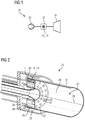
- FIG. 1 schematically shows a gas turbine 31.
- This comprises a compressor section 32, a combustion chamber section 33 and a turbine section 34, and a combustion chamber 27 with at least one burner 23 in the region of the combustion chamber section 33.
- a burner 23 is described in more detail.
- the burner 23 has a fuel nozzle body 1, which in the FIGS. 3 to 10 is described in more detail.
- combustion chambers 27 which are arranged in the combustion chamber section 33.
- a gaseous or liquid fuel for example gas or oil, is injected into the combustion chambers 27 via burners 23 or fuel nozzles.
- Fuel nozzle bodies include fuel nozzles / openings for liquid and gaseous fuels. The resulting air / fuel mixture is ignited and burned in the combustion chambers 27. The hot combustion gases flow from the combustor section 33 into the turbine section 34 where they expand and cool.
- FIG. 2 shows schematically and by way of example a burner 23, in particular a jet burner, in section with a so-called nozzle carrier 35.
- the nozzle carrier 35 comprises a combustion zone 36 facing during operation of a hot side 37 and an opposite, remote from the combustion zone 36 cold side 38, wherein Vormischröhren 30 im Nozzle carrier 35 from the cold side 38 to the hot side 37, so parallel to the main axis 39 of the burner 23 extend, each with an input 28 to a premix on the cold side 38 and an outlet 40 on the hot side 37th
- the premix tubes 30 serve as jet nozzles, which in the present example are arranged on two circles and at the entrances 28 of which fuel nozzle bodies 1 are arranged.
- fuel 6, 10 and compressor air 29 flow through the jet nozzles, i. the Vormischröhren 30, and arrive at the outlets 40 of the jet nozzles as a fuel-air mixture in the confined by a shell 41 combustion chamber 27th
- the FIG. 3 shows schematically and by way of example a fuel nozzle body 42 with oil and gas injection according to the prior art.
- the fuel nozzle body 42 has a rear end 2 for fuel supply to the fuel nozzle body 42 and a front end 3 with different fuel associated openings 5, 9.
- the fuel nozzle body 42 comprises a from the rear end 2 to the front end 3 extending outer tube 4 with radial openings 5 for a first fuel 6 in the region of the front end 3 and an outer tube 4 concentrically arranged inner tube 7, which opens in the region of the front end 3 in a nozzle head 8, the further openings 9 for a second fuel 10 has.
- the fuel nozzle body 42 is arranged at the inlet 28 of a premixing section.
- compressed air 29 flows on the fuel nozzle body 42
- gaseous fuel 6 is passed through the annular channel 21, which is formed by the inner 7 and the outer tube 4, and injected via the radial openings 5 in the air flow 29 surrounding the fuel nozzle body 42.
- oil operation the oil is supplied via the inner tube 7 and the nozzle head 8 with the other openings 9 for the injection of oil 10 in the surrounding air flow 29.
- the annular channel 21 thus acts as a gas line 22 and the inner tube 7 as an oil line 20th
- FIG. 4 shows a fuel nozzle body 1 according to the invention with thermal compensation function, which is achieved in that in the region of the front end 3, the inner tube 7 by two fits 11, 12, which are arranged axially between the radial openings 5 and the other openings 9, in the outer tube 4 is guided.
- FIGS. 5 and 6 show the inner tube 7 in the region of the front end 3 in perspective view and in section. You can see the first fit 11, the second fit 12, and a circumferential web 15th FIG. 7 shows the "counterpart", the outer tube 4 with the radial openings 5 for the first fuel. 6
- FIGS. 8 and 9 show the front end 3 of the fuel nozzle body 1 in perspective view and in section.
- FIG. 8 are essentially the outer tube 4, a web 15 of the inner tube 7 and the nozzle head 8 with the other openings 9 for the other fuel 10 to see.
- the nozzle head 8 is releasably connected to the inner tube 7, screwed in the example shown (see screw 24).
- the gap seal 14 of the first fit 11 is designed so that a minimal controlled leakage occurs during operation. In particular, less than 5% leakage based on the entire injection area on the first fit 11 should take place.
- the second fit 12 is designed to guarantee a tighter fit in each load case than the first fit 11, also called a leakage fit, and thus no contact of the first fit 11 with the inside of the outer tube 4, so that the leak defines over the first fit 11 is. In particular, the second fit 12 is tolerated more tightly than the first fit 11.
- second fit 12 is star-shaped (in the sectional drawing of FIG. 9 not to be seen, but in the embodiment of the FIG. 10 ).
- FIG. 9 It can also be seen that in the region of the front end 3, the inner tube 7 protrudes from the outer tube 4.
- the arranged on the protruding from the outer tube 4 part of the inner tube 7 circumferential ridge 15 is also in the FIG. 8 to recognize.
- This web 15 can be used as a plant for the nozzle head 8.
- FIG. 9 shows the expansion path 25 between the front end of the outer tube 4 and the web 15th
- FIG. 10 shows an alternative use for the web 15.
- a sleeve 16 is detachably connected at its first end 17 to the front end 3 of the outer tube 4, for example screwed.
- the sleeve 16 engages with a radially inwardly directed board 19, the circumferential ridge 15 of the inner tube 7.
- the sleeve 16 is intended to prevent loss of the inner tube 7.
- FIG. 10 further shows that the sleeve 16 is carried out flow-optimized and tapers towards the front end 3.
Landscapes
- Engineering & Computer Science (AREA)
- Chemical & Material Sciences (AREA)
- Combustion & Propulsion (AREA)
- Mechanical Engineering (AREA)
- General Engineering & Computer Science (AREA)
- Nozzles For Spraying Of Liquid Fuel (AREA)
Description
- Die Erfindung betrifft einen Brennstoffdüsenkörper, insbesondere für einen Brenner einer Gasturbine, und bezieht sich auf die Kompensation thermischer Dehnungen. Die Erfindung betrifft ferner einen Brenner sowie eine Gasturbine.
- Eine Brennstoffdüse bzw. ein Brennstoffdüsenkörper für den Gas- und Ölbetrieb ist je nach Betriebsart unterschiedlichen Temperaturen ausgesetzt, weshalb Maßnahmen zur thermischen Kompensation notwendig sind. Eine solche Maßnahme ist die Anbringung eines Bellow-Kompensators an geeigneter Stelle, was aus Platzgründen oft nicht zu realisieren und wenn doch, vergleichsweise teuer ist.
US 5410884 beschreibt einen Brennstoffdüsenkörper mit den Merkmalen des Oberbegriffs des Anspruchs 1. Aufgabe der Erfindung ist es daher, einen Brennstoffdüsenkörper anzugeben, bei dem das Problem der thermischen Kompensation kostengünstig gelöst ist. Weitere Aufgaben der Erfindung sind die Angaben eines entsprechenden Brenners bzw. einer entsprechenden Gasturbine. - Die auf den Brennstoffdüsenkörper gerichtete Aufgabe wird durch die Angabe eines Brennstoffdüsenkörpers nach Anspruch 1 gelöst. Die auf den Brenner bezogene Aufgabe wird durch die Angabe eines Brenners nach Anspruch 12 gelöst. Die auf die Gasturbine bezogene Aufgabe wird durch die Angabe einer Gasturbine nach Anspruch 13 gelöst. Die abhängigen Ansprüche enthalten vorteilhafte Ausgestaltungen der Erfindung.
- Der Brennstoffdüsenkörper mit einem rückwärtigen Ende und einem vorderen Ende umfasst nach der Erfindung eine sich vom rückwärtigen Ende zum vorderen Ende erstreckende äußere Röhre mit radialen Öffnungen für einen ersten Brennstoff im Bereich des vorderen Endes und eine zur äußeren Röhre konzentrisch angeordnete innere Röhre, die im Bereich des vorderen Endes in einen Düsenkopf mündet, der weitere Öffnungen für einen zweiten Brennstoff aufweist, wobei im Bereich des vorderen Endes die innere Röhre durch zwei Passungen, die axial zwischen den radialen Öffnungen und den weiteren Öffnungen angeordnet sind, in der äußeren Röhre geführt ist.
- Der Brennstoffdüsenkörper ist also mit einer selbstregelnden Kompensationseinheit ausgeführt. Die innere Röhre ist verschiebbar in der äußeren Röhre, die zusammen mit der inneren Röhre einen Ringkanal bildet, gelagert und so ausgelegt, dass sie die maximalen thermischen Dehnungen der beiden Systeme ausgleichen kann.
- Der erfinderische Brennstoffdüsenkörper ist durch zwei Passungen gekennzeichnet.
- Die den radialen Öffnungen nächste, erste Passung ist als um die innere Röhre umlaufender Steg ausgeführt. Diese Form ist einfach und wirksam.
- Damit der an der ersten Passung durchgelassene Brennstoff in die Brennkammer abgegeben werden kann, ist gemäß der Erfindung, die zweite Passung mit mindestens einer Unterbrechung auf dem Umfang ausgeführt, d.h. beispielsweise sternförmig, so dass die zweite Passung nicht am gesamten Umfang an der Innenseite der äußeren Röhre anliegt, sondern nur in einzelnen Segmenten, oder als umlaufender Steg, ähnlich der ersten Passung, aber mit Unterbrechungen. In den offen gelassenen Bereichen kann der "Leckage-Brennstoff" sicher an der zweiten Passung vorbei und in die Brennkammer strömen.
- In einer vorteilhaften Ausführungsform der Erfindung weist die erste Passung engere Passungsanforderungen auf, als die zweite Passung. Insbesondere ist für die erste Passung (auch Leckage-Passung) ein im Vergleich zur zweiten Passung größerer Spalt, jedoch mit engerer Passung, definiert, der folglich eine vergleichsweise große Leckage (beispielsweise bis zu 5% bezogen auf vorhandene Injektionslöcher) zulässt, jedoch nur eine Streuung <1% über alle Injektoren ermöglicht. So kann ein möglichst geringer Einfluss auf das Gas/Luftgemisch sichergestellt werden.
- In einer weiteren vorteilhaften Ausführungsform weist die zweite Passung einen engeren Spalt als die erste Passung auf. Der engere Spalt in der zweiten Passung bewirkt, dass ein ansonsten zu erwartender Abrieb im Bereich der ersten Passung, d.h. der Leckage-Passung, vermieden wird. Damit wird eine möglichst dauerhaft stabile Leckage-Passung über die gesamte Betriebsdauer gewährleistet, indem die erste Passung in keinem Fall zur äußeren Röhre Kontakt hat und somit immer ein Ringspalt realisiert wird.
- Damit die beiden Röhren dauerhaft optimal ineinander geführt werden können, ist es weiterhin vorteilhaft, wenn die zweite Passung verchromt ist.
- Alternativ kann es vorteilhaft sein, wenn die zweite Passung gehärtet ist, so dass die zweite Passung an ihrer Oberfläche eine höhere Härte aufweist als ihr Trägermaterial.
- Hinsichtlich des Düsenkopfes ist es vorteilhaft, wenn dieser mit der inneren Röhre lösbar verbunden ist. Dies erlaubt den einfacheren und kostengünstigeren Tausch bei Servicearbeiten.
- In einer vorteilhaften Ausführungsform ragt im Bereich des vorderen Endes die innere Röhre aus der äußeren Röhre heraus und auf dem aus der äußeren Röhre ragenden Teil der inneren Röhre ist ein umlaufender Steg angeordnet.
- Dieser Steg kann als Anlage für den Düsenkopf verwendet werden.
- Alternativ kann ein solcher Steg aber auch in Kombination mit einer Hülse, die an ihrem ersten Ende mit dem vorderen Ende der äußeren Röhre lösbar verbunden ist und an ihrem zweiten Ende mit einem radial nach innen gerichteten Bord den umlaufenden Steg der inneren Röhre hintergreift, als Verliersicherung für die innerer Röhre dienen.
- Dabei ist es zweckmäßig, wenn die Hülse strömungsoptimiert ausgeführt ist.
- Bevorzugt ist die innere Röhre eine Ölleitung und dient der Versorgung des Düsenkopfes.
- Weiterhin bevorzugt ist der durch innere und äußere Röhre gebildete Ringkanal eine Gasleitung.
- Ein erfindungsgemäßer Brenner, der insbesondere ein Gasturbinenbrenner sein kann, ist mit einem erfindungsgemäßen Brennstoffdüsenkörper ausgestattet.
- Vorteilhafter Weise umfasst eine Gasturbine mit einem Verdichter, einer Turbine, sowie einer Brennkammer einen solchen Brenner.
- Weitere Merkmale, Eigenschaften und Vorteile der vorliegenden Erfindung ergeben sich aus der nachfolgenden Beschreibung von Ausführungsbeispielen unter Bezugnahme auf die beiliegenden Figuren.
- Figur 1
- zeigt das Schema einer Gasturbine,
- Figur 2
- zeigt die Ansicht eines Strahlbrenners,
- Figur 3
- zeigt einen Brennstoffdüsenkörper mit Öl- und Gaseindüsung nach dem Stand der Technik ohne thermische Kompensationsfunktion,
- Figur 4
- zeigt einen Brennstoffdüsenkörper mit Öl- und Gaseindüsung nach der Erfindung mit thermischer Kompensationsfunktion,
- Figur 5
- zeigt eine innere Röhre im Bereich des vorderen Endes in perspektivischer Ansicht,
- Figur 6
- zeigt eine innere Röhre im Bereich des vorderen Endes im Schnitt,
- Figur 7
- zeigt eine äußere Röhre im Bereich des vorderen Endes im Schnitt,
- Figur 8
- zeigt das vordere Ende des Brennstoffdüsenkörpers in perspektivischer Ansicht,
- Figur 9
- zeigt das vordere Ende des Brennstoffdüsenkörpers im Schnitt und
- Figur 10
- zeigt das vordere Ende des Brennstoffdüsenkörpers mit Verlierhülse.
- Die
Figur 1 zeigt schematisch eine Gasturbine 31. Diese umfasst einen Verdichterabschnitt 32, einen Brennkammerabschnitt 33 und einen Turbinenabschnitt 34, sowie eine Brennkammer 27 mit mindestens einem Brenner 23 im Bereich des Brennkammerschnittes 33. InFigur 2 ist ein solcher Brenner 23 näher beschrieben. Der Brenner 23 weist einen Brennstoffdüsenkörper 1 auf, der in denFiguren 3 bis 10 näher beschrieben ist. - Im Betrieb der Gasturbine 31 wird Luft durch einen Lufteinlass des Verdichterabschnitts 32 eingesaugt und dort komprimiert. Die komprimierte Luft wird Brennkammern 27 zugeführt, die im Brennkammerschnitt 33 angeordnet sind. In die Brennkammern 27 wird über Brenner 23 bzw. Brennstoffdüsen auch ein gasförmiger oder flüssiger Brennstoff, beispielsweise Gas oder Öl, eingedüst. Dabei umfassen Brennstoffdüsenkörper Brennstoffdüsen/Öffnungen für flüssige und gasförmige Brennstoffe. Das entstehende Luft/Brennstoffgemisch wird gezündet und in den Brennkammern 27 verbrannt. Die heißen Verbrennungsabgase strömen vom Brennkammerabschnitt 33 in den Turbinenabschnitt 34, wo sie expandieren und abkühlen.
- Die
Figur 2 zeigt schematisch und beispielhaft einen Brenner 23, insbesondere einen Strahlbrenner, im Schnitt mit einem sogenannten Düsenträger 35. Der Düsenträger 35 umfasst eine im Betrieb einer Verbrennungszone 36 zugewandte Heißseite 37 und eine gegenüberliegende, von der Verbrennungszone 36 abgewandte Kaltseite 38, wobei sich Vormischröhren 30 im Düsenträger 35 von der Kaltseite 38 zur Heißseite 37, also parallel zur Hauptachse 39 des Brenners 23 erstrecken, mit je einem Eingang 28 zu einer Vormischstrecke auf der Kaltseite 38 und einem Auslass 40 auf der Heißseite 37. - Die Vormischröhren 30 dienen als Strahldüsen, die im vorliegenden Beispiel auf zwei Kreisen angeordnet sind und an deren Eingängen 28 Brennstoffdüsenkörper 1 angeordnet sind. Im Betrieb strömen ein Brennstoff 6, 10 und Verdichterluft 29 durch die Strahldüsen, d.h. die Vormischröhren 30, und gelangen an den Auslässen 40 der Strahldüsen als Brennstoff-LuftGemisch in die durch eine Ummantelung 41 begrenzte Brennkammer 27.
- Die
Figur 3 zeigt schematisch und beispielhaft einen Brennstoffdüsenkörper 42 mit Öl- und Gaseindüsung nach dem Stand der Technik. Der Brennstoffdüsenkörper 42 hat ein rückwärtiges Ende 2 für die Brennstoffzufuhr zum Brennstoffdüsenkörper 42 und ein vorderes Ende 3 mit verschiedenen Brennstoffen zugeordneten Öffnungen 5, 9. Insbesondere umfasst der Brennstoffdüsenkörper 42 eine sich vom rückwärtigen Ende 2 zum vorderen Ende 3 erstreckende äußere Röhre 4 mit radialen Öffnungen 5 für einen ersten Brennstoff 6 im Bereich des vorderen Endes 3 und eine zur äußeren Röhre 4 konzentrisch angeordnete innere Röhre 7, die im Bereich des vorderen Endes 3 in einen Düsenkopf 8 mündet, der weitere Öffnungen 9 für einen zweiten Brennstoff 10 aufweist. Der Brennstoffdüsenkörper 42 ist am Eingang 28 einer Vormischstrecke angeordnet. Im Betrieb strömt komprimierte Luft 29 am Brennstoffdüsenkörper 42 vorbei in eine Vormischröhre 30. Im Gasbetrieb wird gasförmiger Brennstoff 6 durch den Ringkanal 21 geführt, der durch die innere 7 und die äußere Röhre 4 gebildet wird, und über die radialen Öffnungen 5 in den den Brennstoffdüsenkörper 42 umgebenden Luftstrom 29 eingedüst. Im Ölbetrieb erfolgt die Ölzufuhr über die innere Röhre 7 und den Düsenkopf 8 mit den weiteren Öffnungen 9 für die Eindüsung von Öl 10 in den umgebenden Luftstrom 29. Der Ringkanal 21 fungiert somit als Gasleitung 22 und die innerer Röhre 7 als Ölleitung 20. -
Figur 4 zeigt einen Brennstoffdüsenkörper 1 nach der Erfindung mit thermischer Kompensationsfunktion, die dadurch erreicht wird, dass im Bereich des vorderen Endes 3 die innere Röhre 7 durch zwei Passungen 11, 12, die axial zwischen den radialen Öffnungen 5 und den weiteren Öffnungen 9 angeordnet sind, in der äußeren Röhre 4 geführt ist. -
Figuren 5 und 6 zeigen die innere Röhre 7 im Bereich des vorderen Endes 3 in perspektivischer Ansicht und im Schnitt. Zu sehen sind die erste Passung 11, die zweite Passung 12, sowie ein umlaufender Steg 15.Figur 7 zeigt das "Gegenstück", die äußerer Röhre 4 mit den radialen Öffungen 5 für den ersten Brennstoff 6. - Die
Figuren 8 und 9 zeigen das vordere Ende 3 des Brennstoffdüsenkörpers 1 in perspektivischer Ansicht und im Schnitt. - In
Figur 8 sind im Wesentlichen die äußere Röhre 4, ein Steg 15 der inneren Röhre 7 und der Düsenkopf 8 mit den weiteren Öffnungen 9 für den weiteren Brennstoff 10 zu sehen. - In der
Figur 9 ist zu sehen, dass der Düsenkopf 8 mit der inneren Röhre 7 lösbar verbunden, im gezeigten Beispiel geschraubt ist (siehe Verschraubung 24). Die Spaltdichtung 14 der ersten Passung 11 ist so ausgeführt, dass im Betrieb eine minimale kontrollierte Leckage erfolgt. Insbesondere soll weniger als 5% Leckage bezogen auf den gesamten Eindüsungsbereich über die erste Passung 11 erfolgen. Die zweite Passung 12 ist so ausgelegt, dass sie in jedem Lastfall eine engere Passung garantiert als die erste Passung 11, auch Leckagepassung genannt, und somit kein Kontakt der ersten Passung 11 zur Innenseite der äußeren Röhre 4 entsteht, so dass die Leckage über die erste Passung 11 definiert ist. Insbesondere ist die zweite Passung 12 enger als die erste Passung 11 toleriert. Damit das funktioniert, darf die Passung 12 nicht wie Passung 11 als umlaufender Steg 13 um den ganzen Umfang anliegen. Aus diesem Grund ist zweite Passung 12 sternförmig ausgeführt (in der Schnittzeichnung derFigur 9 nicht zu sehen, aber in der Ausführungsform derFigur 10 ). - In
Figur 9 ist ferner zu sehen, dass im Bereich des vorderen Endes 3 die innere Röhre 7 aus der äußeren Röhre 4 herausragt. Der auf dem aus der äußeren Röhre 4 ragenden Teil der inneren Röhre 7 angeordnete umlaufende Steg 15 ist auch in derFigur 8 zu erkennen. Dieser Steg 15 kann als Anlage für den Düsenkopf 8 verwendet werden.Figur 9 zeigt den Dehnungsweg 25 zwischen dem vorderen Ende der äußeren Röhre 4 und dem Steg 15. -
Figur 10 zeigt eine alternative Verwendung für den Steg 15. Hierbei ist eine Hülse 16 an ihrem ersten Ende 17 mit dem vorderen Ende 3 der äußeren Röhre 4 lösbar verbunden, z.B. verschraubt. An ihrem zweiten Ende 18 hintergreift die Hülse 16 mit einem radial nach innen gerichteten Bord 19 den umlaufenden Steg 15 der inneren Röhre 7. Die Hülse 16 soll einen Verlust der inneren Röhre 7 verhindern.Figur 10 zeigt ferner, dass die Hülse 16 strömungsoptimiert ausgeführt ist und sich zum vorderen Ende 3 hin verjüngt.
Claims (13)
- Brennstoffdüsenkörper (1) mit einem rückwärtigen Ende (2) und einem vorderen Ende (3), umfassend eine sich vom rückwärtigen Ende (2) zum vorderen Ende (3) erstreckende äußere Röhre (4) mit radialen Öffnungen (5) für einen ersten Brennstoff (6) im Bereich des vorderen Endes (3) und eine zur äußeren Röhre (4) konzentrisch angeordnete innere Röhre (7), die im Bereich des vorderen Endes (3) in einen Düsenkopf (8) mündet, der weitere Öffnungen (9) für einen zweiten Brennstoff (10) aufweist, dadurch gekennzeichnet, dass im Bereich des vorderen Endes (3) die innere Röhre (7) durch zwei Passungen (11, 12), die axial zwischen den radialen Öffnungen (5) und den weiteren Öffnungen (9) angeordnet sind, in der äußeren Röhre (4) geführt ist, dass die den radialen Öffnungen (5) nächste, erste Passung (11) als um die innere Röhre (7) umlaufender Steg (13) ausgeführt ist und wobei die zweite Passung (12) mit mindestens einer Unterbrechung auf dem Umfang ausgeführt ist.
- Brennstoffdüsenkörper (1) nach Anspruch 1, wobei die erste Passung (11) engere Passungsanforderungen aufweist als die zweite Passung (12).
- Brennstoffdüsenkörper (1) nach einem der vorhergehenden Ansprüche, wobei die zweite Passung (12) einen engeren Spalt als die erste Passung (11) aufweist.
- Brennstoffdüsenkörper (1) nach einem der vorhergehenden Ansprüche, wobei die zweite Passung (12) verchromt ist.
- Brennstoffdüsenkörper (1) nach einem der vorhergehenden Ansprüche, wobei die zweite Passung (12) gehärtet ist.
- Brennstoffdüsenkörper (1) nach einem der vorhergehenden Ansprüche, wobei der Düsenkopf (8) mit der inneren Röhre (7) lösbar verbunden ist.
- Brennstoffdüsenkörper (1) nach einem der vorhergehenden Ansprüche, wobei im Bereich des vorderen Endes (3) die innere Röhre (7) aus der äußeren Röhre (4) herausragt und auf dem aus der äußeren Röhre (4) ragenden Teil der inneren Röhre (7) ein umlaufender Steg (15) angeordnet ist.
- Brennstoffdüsenkörper (1) nach Anspruch 7, wobei eine Hülse (16) an ihrem ersten Ende (17) mit dem vorderen Ende (3) der äußeren Röhre (4) lösbar verbunden ist und an ihrem zweiten Ende (18) mit einem radial nach innen gerichteten Bord (19) den umlaufenden Steg (15) der inneren Röhre (7) hintergreift.
- Brennstoffdüsenkörper (1) nach Anspruch 8, wobei die Hülse (16) strömungsoptimiert ausgeführt ist.
- Brennstoffdüsenkörper (1) nach einem der vorhergehenden Ansprüche, wobei die innere Röhre (7) eine Ölleitung (20) ist.
- Brennstoffdüsenkörper (1) nach einem der vorhergehenden Ansprüche, wobei der durch innere (7) und äußere Röhre (4) gebildete Ringkanal (21) eine Gasleitung (22) ist.
- Brenner (23) mit einem Brennstoffdüsenkörper (1) nach einem der vorhergehenden Ansprüche.
- Gasturbine (24) mit einem Verdichter (25), einer Turbine (26), sowie einer Brennkammer (27) mit mindestens einem Brenner (23) nach Anspruch 12.
Applications Claiming Priority (2)
| Application Number | Priority Date | Filing Date | Title |
|---|---|---|---|
| DE102014220689.8A DE102014220689A1 (de) | 2014-10-13 | 2014-10-13 | Brennstoffdüsenkörper |
| PCT/EP2015/073283 WO2016058903A1 (de) | 2014-10-13 | 2015-10-08 | Brennstoffdüsenkörper |
Publications (2)
| Publication Number | Publication Date |
|---|---|
| EP3134681A1 EP3134681A1 (de) | 2017-03-01 |
| EP3134681B1 true EP3134681B1 (de) | 2018-03-07 |
Family
ID=54293231
Family Applications (1)
| Application Number | Title | Priority Date | Filing Date |
|---|---|---|---|
| EP15778915.7A Active EP3134681B1 (de) | 2014-10-13 | 2015-10-08 | Brennstoffdüsenkörper |
Country Status (6)
| Country | Link |
|---|---|
| US (1) | US10591165B2 (de) |
| EP (1) | EP3134681B1 (de) |
| CN (1) | CN106662324B (de) |
| CA (1) | CA2958974C (de) |
| DE (1) | DE102014220689A1 (de) |
| WO (1) | WO2016058903A1 (de) |
Families Citing this family (2)
| Publication number | Priority date | Publication date | Assignee | Title |
|---|---|---|---|---|
| DE102017120370B4 (de) * | 2017-09-05 | 2019-06-06 | Deutsches Zentrum für Luft- und Raumfahrt e.V. | Brennerkopf, Brennersystem und Verfahren zum Betreiben des Brennersystems |
| KR102583223B1 (ko) | 2022-01-28 | 2023-09-25 | 두산에너빌리티 주식회사 | 연소기용 노즐, 연소기 및 이를 포함하는 가스터빈 |
Family Cites Families (16)
| Publication number | Priority date | Publication date | Assignee | Title |
|---|---|---|---|---|
| JPS61223418A (ja) * | 1985-03-28 | 1986-10-04 | Sumitomo Metal Ind Ltd | バ−ナ装置 |
| DD249612A3 (de) * | 1985-05-14 | 1987-09-16 | Stroemungsmasch Veb | Fluessigkeitsbrenner mit dampfdruckzerstaeubung |
| EP0337141A1 (de) | 1988-03-31 | 1989-10-18 | Siemens Aktiengesellschaft | Lichtwellenleiter-Durchführung für optoelektronische Module und Verfahren zu ihrer Herstellung |
| US5410884A (en) * | 1992-10-19 | 1995-05-02 | Mitsubishi Jukogyo Kabushiki Kaisha | Combustor for gas turbines with diverging pilot nozzle cone |
| DE4326802A1 (de) * | 1993-08-10 | 1995-02-16 | Abb Management Ag | Brennstofflanze für flüssige und/oder gasförmige Brennstoffe sowie Verfahren zu deren Betrieb |
| GB9321505D0 (en) * | 1993-10-19 | 1993-12-08 | Europ Gas Turbines Ltd | Fuel injector |
| AU1995199A (en) * | 1997-10-10 | 1999-05-03 | Westinghouse Electric Corporation | Fuel nozzle assembly for a low nox combustor |
| JP2000039147A (ja) * | 1998-07-21 | 2000-02-08 | Mitsubishi Heavy Ind Ltd | フレキシブルジョイントを備えた燃焼器パイロットノズル |
| DE19905995A1 (de) * | 1999-02-15 | 2000-08-17 | Asea Brown Boveri | Brennstofflanze zum Eindüsen von flüssigen und/oder gasförmigen Brennstoffen in eine Brennkammer sowie Verfahren zum Betrieb einer solchen Brennstofflanze |
| US7290394B2 (en) * | 2002-11-21 | 2007-11-06 | Parker-Hannifin Corporation | Fuel injector flexible feed with moveable nozzle tip |
| CN200958753Y (zh) * | 2006-06-30 | 2007-10-10 | 浦炳良 | 炉用油喷嘴 |
| EP1936276A1 (de) * | 2006-12-22 | 2008-06-25 | Siemens Aktiengesellschaft | Brenner für eine Gasturbine |
| US20100319353A1 (en) * | 2009-06-18 | 2010-12-23 | John Charles Intile | Multiple Fuel Circuits for Syngas/NG DLN in a Premixed Nozzle |
| EP2400216B1 (de) * | 2010-06-23 | 2014-12-24 | Alstom Technology Ltd | Lanze für einen Reheat Brenner |
| US9133767B2 (en) * | 2011-08-02 | 2015-09-15 | Siemens Energy, Inc | Fuel injecting assembly for gas turbine engine including cooling gap between supply structures |
| US8801428B2 (en) | 2011-10-04 | 2014-08-12 | General Electric Company | Combustor and method for supplying fuel to a combustor |
-
2014
- 2014-10-13 DE DE102014220689.8A patent/DE102014220689A1/de not_active Ceased
-
2015
- 2015-10-08 US US15/503,993 patent/US10591165B2/en active Active
- 2015-10-08 CN CN201580031080.XA patent/CN106662324B/zh active Active
- 2015-10-08 WO PCT/EP2015/073283 patent/WO2016058903A1/de active Application Filing
- 2015-10-08 EP EP15778915.7A patent/EP3134681B1/de active Active
- 2015-10-08 CA CA2958974A patent/CA2958974C/en active Active
Also Published As
| Publication number | Publication date |
|---|---|
| CN106662324B (zh) | 2019-03-19 |
| US20170276370A1 (en) | 2017-09-28 |
| CN106662324A (zh) | 2017-05-10 |
| CA2958974A1 (en) | 2016-04-21 |
| WO2016058903A1 (de) | 2016-04-21 |
| CA2958974C (en) | 2018-11-13 |
| EP3134681A1 (de) | 2017-03-01 |
| US10591165B2 (en) | 2020-03-17 |
| DE102014220689A1 (de) | 2016-04-14 |
Similar Documents
| Publication | Publication Date | Title |
|---|---|---|
| EP2196734A1 (de) | Brennstofflanze für einen Brenner | |
| DE102015112767A1 (de) | Brennstoffinjektoranordnungen in Verbrennungsturbinen | |
| EP2307806B1 (de) | Brenneranordnung für fluidische brennstoffe und verfahren zum herstellen der brenneranordnung | |
| EP1456583B1 (de) | Verfahren zum Eindüsen eines Brennstoff-/Luftgemisches in eine Brennkammer | |
| DE2147135A1 (de) | Brennkammermantel insbesondere für Gasturbinentriebwerke | |
| EP2470834B1 (de) | Brenner, insbesondere für gasturbinen | |
| CH703884B1 (de) | Brennstoffdüsenanordnung für Gasturbinensysteme sowie Brenner. | |
| DE112012006144T5 (de) | Brennkammeranordnung einer Turbomaschine | |
| DE102011051326A1 (de) | Brennstoffdüsenanordnung | |
| EP2196733A1 (de) | Brennerlanze | |
| EP2439447A1 (de) | Brennstoffdüse, Gasturbinenbrennkammer und Brenner mit einer solchen Brennstoffdüse | |
| EP2264370B1 (de) | Brenneranordnung für eine Verfeuerungsanlage zum Verfeuern fluidischer Brennstoffe und Verfahren zum Betrieb einer solchen Brenneranordnung | |
| DE102015113146A1 (de) | Systeme und Vorrichtungen im Zusammenhang mit Gasturbinenbrennkammern | |
| EP3134681B1 (de) | Brennstoffdüsenkörper | |
| EP2409086B1 (de) | Brenneranordnung für eine gasturbine | |
| DE102014105942A1 (de) | Wirbelbeeinflussungsstruktur für ein Turbinensystem | |
| DE2126648A1 (de) | Brennkammer | |
| EP3143335B1 (de) | Brenner für eine verbrennungsmaschine und verbrennungsmaschine | |
| DE102007048487B4 (de) | Brenner für einen Industrieofen | |
| EP2558781B1 (de) | Drallerzeuger für einen brenner | |
| EP2295858A1 (de) | Stabilisierung der Flamme eines Brenners | |
| EP2449310B1 (de) | Brenner insbesondere für gasturbinen | |
| EP3301371A1 (de) | Brennkammersystem, Verwendung eines brennkammersystems mit einer angeschlossenen Turbine und Verfahren zur Durchführung eines Verbrennungsprozesses | |
| DE112017001755T5 (de) | Gasturbinenbrenner | |
| WO2015176908A1 (de) | Brenner mit brennstoffverteilerring |
Legal Events
| Date | Code | Title | Description |
|---|---|---|---|
| PUAI | Public reference made under article 153(3) epc to a published international application that has entered the european phase |
Free format text: ORIGINAL CODE: 0009012 |
|
| 17P | Request for examination filed |
Effective date: 20161114 |
|
| AK | Designated contracting states |
Kind code of ref document: A1 Designated state(s): AL AT BE BG CH CY CZ DE DK EE ES FI FR GB GR HR HU IE IS IT LI LT LU LV MC MK MT NL NO PL PT RO RS SE SI SK SM TR |
|
| AX | Request for extension of the european patent |
Extension state: BA ME |
|
| RAP1 | Party data changed (applicant data changed or rights of an application transferred) |
Owner name: SIEMENS AKTIENGESELLSCHAFT |
|
| GRAP | Despatch of communication of intention to grant a patent |
Free format text: ORIGINAL CODE: EPIDOSNIGR1 |
|
| DAV | Request for validation of the european patent (deleted) | ||
| DAX | Request for extension of the european patent (deleted) | ||
| INTG | Intention to grant announced |
Effective date: 20171020 |
|
| GRAS | Grant fee paid |
Free format text: ORIGINAL CODE: EPIDOSNIGR3 |
|
| GRAA | (expected) grant |
Free format text: ORIGINAL CODE: 0009210 |
|
| AK | Designated contracting states |
Kind code of ref document: B1 Designated state(s): AL AT BE BG CH CY CZ DE DK EE ES FI FR GB GR HR HU IE IS IT LI LT LU LV MC MK MT NL NO PL PT RO RS SE SI SK SM TR |
|
| REG | Reference to a national code |
Ref country code: GB Ref legal event code: FG4D Free format text: NOT ENGLISH |
|
| REG | Reference to a national code |
Ref country code: CH Ref legal event code: EP Ref country code: AT Ref legal event code: REF Ref document number: 976981 Country of ref document: AT Kind code of ref document: T Effective date: 20180315 |
|
| REG | Reference to a national code |
Ref country code: IE Ref legal event code: FG4D Free format text: LANGUAGE OF EP DOCUMENT: GERMAN |
|
| REG | Reference to a national code |
Ref country code: DE Ref legal event code: R096 Ref document number: 502015003319 Country of ref document: DE |
|
| REG | Reference to a national code |
Ref country code: CH Ref legal event code: NV Representative=s name: SIEMENS SCHWEIZ AG, CH |
|
| REG | Reference to a national code |
Ref country code: NL Ref legal event code: MP Effective date: 20180307 |
|
| REG | Reference to a national code |
Ref country code: LT Ref legal event code: MG4D |
|
| PG25 | Lapsed in a contracting state [announced via postgrant information from national office to epo] |
Ref country code: HR Free format text: LAPSE BECAUSE OF FAILURE TO SUBMIT A TRANSLATION OF THE DESCRIPTION OR TO PAY THE FEE WITHIN THE PRESCRIBED TIME-LIMIT Effective date: 20180307 Ref country code: NO Free format text: LAPSE BECAUSE OF FAILURE TO SUBMIT A TRANSLATION OF THE DESCRIPTION OR TO PAY THE FEE WITHIN THE PRESCRIBED TIME-LIMIT Effective date: 20180607 Ref country code: CY Free format text: LAPSE BECAUSE OF FAILURE TO SUBMIT A TRANSLATION OF THE DESCRIPTION OR TO PAY THE FEE WITHIN THE PRESCRIBED TIME-LIMIT Effective date: 20180307 Ref country code: LT Free format text: LAPSE BECAUSE OF FAILURE TO SUBMIT A TRANSLATION OF THE DESCRIPTION OR TO PAY THE FEE WITHIN THE PRESCRIBED TIME-LIMIT Effective date: 20180307 Ref country code: ES Free format text: LAPSE BECAUSE OF FAILURE TO SUBMIT A TRANSLATION OF THE DESCRIPTION OR TO PAY THE FEE WITHIN THE PRESCRIBED TIME-LIMIT Effective date: 20180307 Ref country code: FI Free format text: LAPSE BECAUSE OF FAILURE TO SUBMIT A TRANSLATION OF THE DESCRIPTION OR TO PAY THE FEE WITHIN THE PRESCRIBED TIME-LIMIT Effective date: 20180307 |
|
| PG25 | Lapsed in a contracting state [announced via postgrant information from national office to epo] |
Ref country code: SE Free format text: LAPSE BECAUSE OF FAILURE TO SUBMIT A TRANSLATION OF THE DESCRIPTION OR TO PAY THE FEE WITHIN THE PRESCRIBED TIME-LIMIT Effective date: 20180307 Ref country code: LV Free format text: LAPSE BECAUSE OF FAILURE TO SUBMIT A TRANSLATION OF THE DESCRIPTION OR TO PAY THE FEE WITHIN THE PRESCRIBED TIME-LIMIT Effective date: 20180307 Ref country code: GR Free format text: LAPSE BECAUSE OF FAILURE TO SUBMIT A TRANSLATION OF THE DESCRIPTION OR TO PAY THE FEE WITHIN THE PRESCRIBED TIME-LIMIT Effective date: 20180608 Ref country code: BG Free format text: LAPSE BECAUSE OF FAILURE TO SUBMIT A TRANSLATION OF THE DESCRIPTION OR TO PAY THE FEE WITHIN THE PRESCRIBED TIME-LIMIT Effective date: 20180607 Ref country code: RS Free format text: LAPSE BECAUSE OF FAILURE TO SUBMIT A TRANSLATION OF THE DESCRIPTION OR TO PAY THE FEE WITHIN THE PRESCRIBED TIME-LIMIT Effective date: 20180307 |
|
| PG25 | Lapsed in a contracting state [announced via postgrant information from national office to epo] |
Ref country code: MT Free format text: LAPSE BECAUSE OF FAILURE TO SUBMIT A TRANSLATION OF THE DESCRIPTION OR TO PAY THE FEE WITHIN THE PRESCRIBED TIME-LIMIT Effective date: 20180307 |
|
| REG | Reference to a national code |
Ref country code: FR Ref legal event code: PLFP Year of fee payment: 4 |
|
| PG25 | Lapsed in a contracting state [announced via postgrant information from national office to epo] |
Ref country code: NL Free format text: LAPSE BECAUSE OF FAILURE TO SUBMIT A TRANSLATION OF THE DESCRIPTION OR TO PAY THE FEE WITHIN THE PRESCRIBED TIME-LIMIT Effective date: 20180307 Ref country code: PL Free format text: LAPSE BECAUSE OF FAILURE TO SUBMIT A TRANSLATION OF THE DESCRIPTION OR TO PAY THE FEE WITHIN THE PRESCRIBED TIME-LIMIT Effective date: 20180307 Ref country code: AL Free format text: LAPSE BECAUSE OF FAILURE TO SUBMIT A TRANSLATION OF THE DESCRIPTION OR TO PAY THE FEE WITHIN THE PRESCRIBED TIME-LIMIT Effective date: 20180307 Ref country code: RO Free format text: LAPSE BECAUSE OF FAILURE TO SUBMIT A TRANSLATION OF THE DESCRIPTION OR TO PAY THE FEE WITHIN THE PRESCRIBED TIME-LIMIT Effective date: 20180307 Ref country code: EE Free format text: LAPSE BECAUSE OF FAILURE TO SUBMIT A TRANSLATION OF THE DESCRIPTION OR TO PAY THE FEE WITHIN THE PRESCRIBED TIME-LIMIT Effective date: 20180307 |
|
| PG25 | Lapsed in a contracting state [announced via postgrant information from national office to epo] |
Ref country code: CZ Free format text: LAPSE BECAUSE OF FAILURE TO SUBMIT A TRANSLATION OF THE DESCRIPTION OR TO PAY THE FEE WITHIN THE PRESCRIBED TIME-LIMIT Effective date: 20180307 Ref country code: SM Free format text: LAPSE BECAUSE OF FAILURE TO SUBMIT A TRANSLATION OF THE DESCRIPTION OR TO PAY THE FEE WITHIN THE PRESCRIBED TIME-LIMIT Effective date: 20180307 Ref country code: SK Free format text: LAPSE BECAUSE OF FAILURE TO SUBMIT A TRANSLATION OF THE DESCRIPTION OR TO PAY THE FEE WITHIN THE PRESCRIBED TIME-LIMIT Effective date: 20180307 |
|
| REG | Reference to a national code |
Ref country code: DE Ref legal event code: R097 Ref document number: 502015003319 Country of ref document: DE |
|
| PG25 | Lapsed in a contracting state [announced via postgrant information from national office to epo] |
Ref country code: PT Free format text: LAPSE BECAUSE OF FAILURE TO SUBMIT A TRANSLATION OF THE DESCRIPTION OR TO PAY THE FEE WITHIN THE PRESCRIBED TIME-LIMIT Effective date: 20180709 |
|
| PLBE | No opposition filed within time limit |
Free format text: ORIGINAL CODE: 0009261 |
|
| STAA | Information on the status of an ep patent application or granted ep patent |
Free format text: STATUS: NO OPPOSITION FILED WITHIN TIME LIMIT |
|
| PG25 | Lapsed in a contracting state [announced via postgrant information from national office to epo] |
Ref country code: DK Free format text: LAPSE BECAUSE OF FAILURE TO SUBMIT A TRANSLATION OF THE DESCRIPTION OR TO PAY THE FEE WITHIN THE PRESCRIBED TIME-LIMIT Effective date: 20180307 |
|
| 26N | No opposition filed |
Effective date: 20181210 |
|
| PG25 | Lapsed in a contracting state [announced via postgrant information from national office to epo] |
Ref country code: SI Free format text: LAPSE BECAUSE OF FAILURE TO SUBMIT A TRANSLATION OF THE DESCRIPTION OR TO PAY THE FEE WITHIN THE PRESCRIBED TIME-LIMIT Effective date: 20180307 |
|
| REG | Reference to a national code |
Ref country code: BE Ref legal event code: MM Effective date: 20181031 |
|
| PG25 | Lapsed in a contracting state [announced via postgrant information from national office to epo] |
Ref country code: MC Free format text: LAPSE BECAUSE OF FAILURE TO SUBMIT A TRANSLATION OF THE DESCRIPTION OR TO PAY THE FEE WITHIN THE PRESCRIBED TIME-LIMIT Effective date: 20180307 Ref country code: LU Free format text: LAPSE BECAUSE OF NON-PAYMENT OF DUE FEES Effective date: 20181008 |
|
| REG | Reference to a national code |
Ref country code: IE Ref legal event code: MM4A |
|
| PG25 | Lapsed in a contracting state [announced via postgrant information from national office to epo] |
Ref country code: BE Free format text: LAPSE BECAUSE OF NON-PAYMENT OF DUE FEES Effective date: 20181031 |
|
| PG25 | Lapsed in a contracting state [announced via postgrant information from national office to epo] |
Ref country code: IE Free format text: LAPSE BECAUSE OF NON-PAYMENT OF DUE FEES Effective date: 20181008 |
|
| PG25 | Lapsed in a contracting state [announced via postgrant information from national office to epo] |
Ref country code: TR Free format text: LAPSE BECAUSE OF FAILURE TO SUBMIT A TRANSLATION OF THE DESCRIPTION OR TO PAY THE FEE WITHIN THE PRESCRIBED TIME-LIMIT Effective date: 20180307 |
|
| PG25 | Lapsed in a contracting state [announced via postgrant information from national office to epo] |
Ref country code: MK Free format text: LAPSE BECAUSE OF NON-PAYMENT OF DUE FEES Effective date: 20180307 Ref country code: HU Free format text: LAPSE BECAUSE OF FAILURE TO SUBMIT A TRANSLATION OF THE DESCRIPTION OR TO PAY THE FEE WITHIN THE PRESCRIBED TIME-LIMIT; INVALID AB INITIO Effective date: 20151008 |
|
| PG25 | Lapsed in a contracting state [announced via postgrant information from national office to epo] |
Ref country code: IS Free format text: LAPSE BECAUSE OF FAILURE TO SUBMIT A TRANSLATION OF THE DESCRIPTION OR TO PAY THE FEE WITHIN THE PRESCRIBED TIME-LIMIT Effective date: 20180707 |
|
| REG | Reference to a national code |
Ref country code: DE Ref legal event code: R081 Ref document number: 502015003319 Country of ref document: DE Owner name: SIEMENS ENERGY GLOBAL GMBH & CO. KG, DE Free format text: FORMER OWNER: SIEMENS AKTIENGESELLSCHAFT, 80333 MUENCHEN, DE |
|
| REG | Reference to a national code |
Ref country code: AT Ref legal event code: MM01 Ref document number: 976981 Country of ref document: AT Kind code of ref document: T Effective date: 20201008 |
|
| PG25 | Lapsed in a contracting state [announced via postgrant information from national office to epo] |
Ref country code: AT Free format text: LAPSE BECAUSE OF NON-PAYMENT OF DUE FEES Effective date: 20201008 |
|
| REG | Reference to a national code |
Ref country code: GB Ref legal event code: 732E Free format text: REGISTERED BETWEEN 20220901 AND 20220907 |
|
| PGFP | Annual fee paid to national office [announced via postgrant information from national office to epo] |
Ref country code: GB Payment date: 20231024 Year of fee payment: 9 |
|
| PGFP | Annual fee paid to national office [announced via postgrant information from national office to epo] |
Ref country code: IT Payment date: 20231024 Year of fee payment: 9 Ref country code: FR Payment date: 20231026 Year of fee payment: 9 Ref country code: DE Payment date: 20231027 Year of fee payment: 9 Ref country code: CH Payment date: 20231102 Year of fee payment: 9 |