EP3134313B1 - Buffer zone for interior aircraft features - Google Patents
Buffer zone for interior aircraft features Download PDFInfo
- Publication number
- EP3134313B1 EP3134313B1 EP15718108.2A EP15718108A EP3134313B1 EP 3134313 B1 EP3134313 B1 EP 3134313B1 EP 15718108 A EP15718108 A EP 15718108A EP 3134313 B1 EP3134313 B1 EP 3134313B1
- Authority
- EP
- European Patent Office
- Prior art keywords
- edge
- aircraft
- bulkhead
- soft seal
- transition
- Prior art date
- Legal status (The legal status is an assumption and is not a legal conclusion. Google has not performed a legal analysis and makes no representation as to the accuracy of the status listed.)
- Active
Links
Images



Classifications
-
- B—PERFORMING OPERATIONS; TRANSPORTING
- B64—AIRCRAFT; AVIATION; COSMONAUTICS
- B64C—AEROPLANES; HELICOPTERS
- B64C1/00—Fuselages; Constructional features common to fuselages, wings, stabilising surfaces or the like
- B64C1/06—Frames; Stringers; Longerons ; Fuselage sections
- B64C1/066—Interior liners
-
- B—PERFORMING OPERATIONS; TRANSPORTING
- B64—AIRCRAFT; AVIATION; COSMONAUTICS
- B64C—AEROPLANES; HELICOPTERS
- B64C1/00—Fuselages; Constructional features common to fuselages, wings, stabilising surfaces or the like
- B64C1/06—Frames; Stringers; Longerons ; Fuselage sections
- B64C1/10—Bulkheads
-
- B—PERFORMING OPERATIONS; TRANSPORTING
- B64—AIRCRAFT; AVIATION; COSMONAUTICS
- B64D—EQUIPMENT FOR FITTING IN OR TO AIRCRAFT; FLIGHT SUITS; PARACHUTES; ARRANGEMENT OR MOUNTING OF POWER PLANTS OR PROPULSION TRANSMISSIONS IN AIRCRAFT
- B64D11/00—Passenger or crew accommodation; Flight-deck installations not otherwise provided for
- B64D11/0023—Movable or removable cabin dividers, e.g. for class separation
-
- B—PERFORMING OPERATIONS; TRANSPORTING
- B64—AIRCRAFT; AVIATION; COSMONAUTICS
- B64F—GROUND OR AIRCRAFT-CARRIER-DECK INSTALLATIONS SPECIALLY ADAPTED FOR USE IN CONNECTION WITH AIRCRAFT; DESIGNING, MANUFACTURING, ASSEMBLING, CLEANING, MAINTAINING OR REPAIRING AIRCRAFT, NOT OTHERWISE PROVIDED FOR; HANDLING, TRANSPORTING, TESTING OR INSPECTING AIRCRAFT COMPONENTS, NOT OTHERWISE PROVIDED FOR
- B64F5/00—Designing, manufacturing, assembling, cleaning, maintaining or repairing aircraft, not otherwise provided for; Handling, transporting, testing or inspecting aircraft components, not otherwise provided for
- B64F5/10—Manufacturing or assembling aircraft, e.g. jigs therefor
-
- B—PERFORMING OPERATIONS; TRANSPORTING
- B64—AIRCRAFT; AVIATION; COSMONAUTICS
- B64D—EQUIPMENT FOR FITTING IN OR TO AIRCRAFT; FLIGHT SUITS; PARACHUTES; ARRANGEMENT OR MOUNTING OF POWER PLANTS OR PROPULSION TRANSMISSIONS IN AIRCRAFT
- B64D11/00—Passenger or crew accommodation; Flight-deck installations not otherwise provided for
- B64D2011/0046—Modular or preassembled units for creating cabin interior structures
Definitions
- the present invention concerns configurations for the interior architecture of an aircraft. More specifically, the present invention concerns a construction for two or more adjacent elements on an aircraft that adjust for dynamic spacing between the elements to help control different gapping requirements between the elements installed in the aircraft.
- an aircraft fuselage is subject to considerable expansion, contraction, bending, corkscrewing, and other flex forces during service (referred herein as “aircraft flexure” or “flexure”).
- Aircraft flexure typically establishes gaps between elements on the aircraft.
- the gaps may be temporary, semi-permanent, or permanent depending upon the nature of the flexure. This gapping occurs, for instance, between wall panels or ceiling panels and bulkhead walls. Gapping can also occur between other aircraft features including interior elements and features.
- Aircraft building tolerances also require significant production time where installers have to cut and fit each component feature keeping in mind ordinary aircraft flexure. Aircraft build tolerances are also impacted by individual component manufacturing tolerances, build sequence installation, jig positioning, manual installation and aircraft structure build tolerances. The sum of these tolerances may create gaps that are independent of aircraft flexure.
- the gap covering comprises a flexible cover region that is arranged between the cabin panels and finished off so as to be substantially flush with surfaces of the panels. In this way, a lightweight economical gap covering which covers gaps in an effective and attractive manner and provides protection against injury is provided.
- the present invention establishes buffer zones at intersections between aircraft features to minimize or eliminate gaps between those features that may otherwise appear.
- an aspect of the present invention to provide an aircraft interior panel configuration between adjacent panels that includes a first interior panel of the adjacent panels having a first edge, a first cavity formed in the first edge, a first soft seal element disposed in the first cavity, and a transition insert disposed adjacent to the first edge such that the first edge overlaps the transition insert.
- the transition insert is adapted to be fixedly mounted in an aircraft interior along an arc, the transition insert extending between the adjacent panels.
- the first soft seal element is biased to press the first edge against a surface of the transition insert.
- the transition element is a bulkhead transition insert.
- the edges are fashioned as hollow structures, defining the cavities that house the soft seal elements.
- edges and soft seal elements are contemplated to be biased against the bulkhead transition insert in the direction vertical to the plane defined by the internal panel such that the first edge is biased to remain in constant contact with a surface of the transition element regardless of a width of a gap between the adjacent panels.
- the adjacent panels are one of an interior ceiling panel.
- the bulkhead transition insert extends between a first and a second bulkhead.
- the first edge is a flexible material.
- the first soft seal element is a flexible material.
- the aircraft interior panel configuration also may include a second panel having a second edge, a second cavity formed in the second edge, and a second soft seal element formed in the second cavity.
- the second soft seal element may be biased to press the second edge against the transition insert such that the second edge is biased to remain in constant contact with the surface of the transition insert regardless of the width of the gap between the adjacent panels and wherein the second edge slides across the transition insert as the adjacent panels move with respect to one another.
- first edge and the second edge may be configured to slide against the surface of the transition insert while being pressed thereagainst.
- the first soft seal element comprises at least one of an elastomeric compound, a polyurethane foam and a resilient polymer.
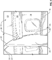
- FIG. 1 there is shown an interior section 10 of an aircraft.
- the interior section 10 includes ceiling panels 12, personal service units 14, sidewalls 16, a side ledge 18, and a bulkhead 20. It is readily apparent from Fig. 1 that there are multiple locations where there may be gaps or spaces between various ones of the interior features, primarily along the longitudinal length of the aircraft.
- two gaps 22 may be established between a bulkhead transition insert 24 and adjacent ceiling panels 12.
- a gap 26 may be established between the sidewall 16 and the bulkhead 20.
- a gap 28 may be established between the personal service unit 14 and the bulkhead 20.
- Another gap 82 may be established between a side ledge 18 and the bulkhead 20.
- Each of these gaps 22, 24, 28, 82 establish locations where the fit and finish of the interior of the aircraft may be diminished during the dynamic conditions associated with aircraft flexure. In particular, during instances of aircraft flexure, among other reasons, the gaps 22, 24, 28, 82 may increase in size, change shape, or otherwise negatively impact the appearance of the interior the aircraft.
- the present invention provides for several embodiments of buffer zones that are contemplated to reduce or eliminate the unsightly appearance of the gaps 22, 24, 28, 82, regardless of the static or dynamic conditions in the aircraft.
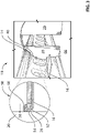
- FIG. 2 there is shown again an interior section 10 of an aircraft.
- a close-up view of the first buffer zone 30 according to the present invention is provided in the enlarged detail included in the drawing.
- the buffer zone 30 is associated with the bulkhead transition insert 24 and the adjacent ceiling panels 12.
- the bulkhead transition insert 24 extends along a circumferential arc within the interior of the aircraft between two bulkhead walls 20.
- the bulkhead transition insert 24 abuts against two soft seal elements 32 on opposite sides thereof.
- the soft seal elements 32 are positioned within cavities 34 established within the edges 36 of the ceiling panels 12.
- a gap 38 exists between the edges 36.
- the gap 38 has a width 40.
- the gap 38 exposes the surface of the bulkhead transition insert 24 so that the bulkhead transition insert 24 is made visible to persons within the interior section 10 of the aircraft.
- the edges 36 of the adjacent ceiling panels 12 extend across the width of the aircraft, along a lateral axis 42 perpendicular to a longitudinal axis 44 of the aircraft.
- the edges 36 form transitions along the entire length of the intersection between the ceiling panels 12 and the bulkhead transition insert 24.
- the edges 36 are made of a flexible material.
- the edges 36 may be greater than one inch wide, or alternatively greater than two inches in width, as required or as desired.
- the edges 36 are allowed to freely move in relation to the bulkhead transition insert 24.
- the flexible material that makes up the edges 36 may be an elastomeric material such as a rubber or polyurethane foam that is able to be compressed and spring back to its regular length during the ordinary compression and expansion of the aircraft fuselage during service.
- the soft seal elements 32 that are disposed within the edges 36 also are contemplated to be made of a flexible material.
- edges 36 are contemplated to be fashioned as hollow structures, defining the cavities 34 that house the soft seal elements 32.
- the edges 36 and soft seal elements 32 are contemplated to be biased against the bulkhead transition insert 24 in the direction of the arrows 46. With this construction, the edges 36 are biased to remain in constant contact with the surface of the bulkhead transition insert 24 regardless of the width 40 of the gap 38 between the edges 36.
- the soft seal elements 32 are contemplated to provide the primary biasing force for the edges 36 of the ceiling panels 12, pressing the edges 36 against the surface of the bulkhead transition insert 24. Due to the bias against the bulkhead transition insert 24 by the soft seal elements 32, the interior surfaces 48 of the edges 36 are pressed against the bulkhead transition insert 24. The interior surfaces 48, biased by the soft seal elements 32, slide across the surface bulkhead transition insert 24 as the ceiling panels 12 move with respect to one another during instances of aircraft flexure. As the edges 36 of the ceiling panels 12 move with respect to one another during aircraft flexure, the width 40 of the gap 38 changes in dimension.
- the soft seal elements 32 in cooperation with the flexible edges 36 of the ceiling panels 12, establish a first embodiment of the buffer zone 30 according to the present invention.
- the buffer zone 30 provides a gap-free transition between the ceiling panels 12 and the bulkhead transition insert 24.
- the creation of any gaps 22 between the edges 36 of the ceiling panels 12 and the bulkhead transition insert 24 is avoided or at least greatly reduced.
- the aesthetic appearance of the interior section 10 of the aircraft is improved regardless of the flexure condition of the aircraft.
- Fig. 3 again shows the interior section 10 of an aircraft.
- the sidewall 16 includes an edge 50 with a soft seal element 52 disposed therein.
- the edge 50 is flexible.
- the edge 50 establishes a cavity 54 that houses the soft seal element 52.
- the soft seal element 52 is biased in the direction of the arrow 56.
- the edge flexibly engages at the gap 26 forming the intersection between the sidewall 16 and the bulkhead 20.
- the flexible edge 52 creates a soft seal between the sidewall 16 and the bulkhead 20.
- the flexible edge 52 is made of a resilient material that may be compressed and bounce back to full length depending on the compression and expansion of the fuselage and the sidewall 16 relative to the bulkhead 20.
- the edge 52 may be at least one inch in width, or alternatively at least two inches in width, as required or as desired.
- the material forming the flexible edge 52 may be an elastomeric compound, a polyurethane foam, or other resilient polymer that is able to be compressed and then re-expanded during service.
- the soft seal element 52 also is contemplated to be made of a similar flexible material.
- the soft seal element 52 in cooperation with the flexible edge 50 of the sidewall 16, establish a second embodiment of a buffer zone 58 not according to the present invention.
- the buffer zone 58 provides a gap-free transition (or substantially gap-free transition) between the sidewall 16 and the bulkhead 20.
- the buffer zone 58 With the buffer zone 58, the creation of any gaps 26 between the edge 50 of the sidewall 16 and the bulkhead 20 is avoided or at least greatly reduced. As a result, the aesthetic appearance of the interior section 10 of the aircraft is improved regardless of the flexure condition of the aircraft.
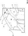
- Fig. 4 is a close up view of the bulkhead 20 that includes bulkhead surfaces 60, 62.
- the bulkhead surfaces 60, 62 are secured to an internal cage frame 64 that is anchored to the interior of the aircraft. It is contemplated that the cage frame 64 is secured to the floor 66 of the aircraft.
- a gap 68 is established between the bulkhead surfaces 60, 62.
- the cage frame 64 is disposed in the gap 68.
- the width 70 of the gap 68 is variable to accommodate the dynamic conditions associated with aircraft flexure.
- Fig. 4 illustrates a third embodiment of a buffer zone 72 between the bulkhead surfaces 60, 62.
- the buffer zone 72 permits the bulkhead surfaces 60, 62 to move in relation to one another on opposite sides of the cage frame 64.
- the bulkhead surfaces 60, 62 are attached to the cage frame 64 via soft seal elements 74. 76.
- the soft seal elements 74. 76 may be made from a flexible material such as foam, rubber, or any other type of elastomeric material.
- the bulkhead surface 60 is permitted to move in the direction of the arrows 78.
- the bulkhead surface 62 is permitted to move in the direction of the arrows 80.
- the soft seal elements 74, 76 flex during moments of aircraft flexure to permit the movement of the bulkhead surfaces 60, 62 in relation to the cage frame 64.
- the soft seal elements 74, 76 may be varied in size so that the bulkhead surfaces 60, 62 may be positioned immediately adjacent to the adjacent side ledges 18. In this fashion, the buffer zone 72 eliminates or at least minimize the formation of any gaps 82 between the side ledges 18 and the bulkhead 20, specifically the bulkhead surfaces 60, 62.
- the soft seal elements 74, 76 in cooperation with the bulkhead surfaces 60, 62 and the side ledges 18, establish the third embodiment of the buffer zone 72 not according to the present invention.
- the buffer zone 72 provides a gap-free transition between the side ledges 18 and the bulkhead surfaces 60, 62 of the bulkhead 20.
- the creation of any gaps 82 between the side ledges 18 and the bulkhead 20 are avoided or at least greatly reduced.
- the aesthetic appearance of the interior section 10 of the aircraft is improved regardless of the flexure condition of the aircraft.
- the side ledges 18 and the cage frame 64 are fixedly mounted within the aircraft.
- the cage frame 64 and the side ledges 18 are two of the features within the aircraft are the features around which other elements in the aircraft are designed.
- the buffer zone 72 cooperates with the buffer zone 58 to minimize or eliminate gaps 82 that may form during dynamic the conditions associated with aircraft flexure.
- Figs. 5-8 illustrate aspects of a fourth embodiment of a buffer zone 84 not according to the present invention.
- the buffer zone 84 is established between ends 86 of the personal service units 14 and the bulkhead 20, specifically the bulkhead surfaces 60, 62.
- the personal service unit 14 has a longitudinal end 86.
- the personal service unit 14 includes a front face 88 that runs longitudinally along the wall of a fuselage.
- a transition end cap 90 At the longitudinal end 86 of the personal service unit 14, there is shown a transition end cap 90.
- the transition end cap 90 is essentially an L-shaped bracket that is attached, at an attachment end 91, to the bulkhead 20.
- a protrusion 92 protrudes from the attachment end 91 of the transition end cap 90 and extends behind the end 86 of the personal service unit 14.
- the protrusion 92 may be provided with a soft seal element 94 that is positioned between the protrusion 92 and the rear surface of the personal service unit 14.
- the buffer zone 84 provides a gap-free transition between the end 86 of the personal service unit 14 and the protrusion 92 on the transition end cap 90 attached to the bulkhead 20.
- the buffer zone 84 With the buffer zone 84, the appearance of any gaps 26 between the bulkhead 20 and the personal service unit 14 are avoided or at least greatly reduced. As a result, the aesthetic appearance of the interior section 10 of the aircraft is improved regardless of the flexure condition of the aircraft.
- the construction offers an additional advantage in that the end 86 of the personal service unit 14 may abut against the bulkhead 20. Since the personal service unit 14 typically covers light strips, such as strips of light emitting diodes, the light strips may extend to a position near to the end 86 of the personal service unit 14. As a result of this construction, the lighting strips may extend to a location very near to the bulkhead 20. This further improves the aesthetic appearance of the interior of the aircraft.
- Fig. 7 is a graphical illustration that shows the relative positioning of the personal service unit 14, the transition end cap 90, and the bulkhead 20.
- the soft seal element 94 is shown.
- the soft seal element 94 is illustrated as being incorporated into the end of the protrusion 92, consistent with other embodiments as discussed above.
- the soft seal element 94 may be attached to the end of the protrusion 92.
- the soft seal element 94 biases the end of the protrusion 92 into contact with the end 86 of the personal service unit 14.
- Fig. 8 is an end view of the transition end cap 90 that is attached to the bulkhead 20.
- the transition end cap 90 is contemplated to be shaped such that it is complimentary to the shape of the personal service unit 14.
Landscapes
- Engineering & Computer Science (AREA)
- Aviation & Aerospace Engineering (AREA)
- Mechanical Engineering (AREA)
- Manufacturing & Machinery (AREA)
- Transportation (AREA)
- Vibration Dampers (AREA)
- Gasket Seals (AREA)
- Aiming, Guidance, Guns With A Light Source, Armor, Camouflage, And Targets (AREA)
- Connection Of Plates (AREA)
Description
- The present invention concerns configurations for the interior architecture of an aircraft. More specifically, the present invention concerns a construction for two or more adjacent elements on an aircraft that adjust for dynamic spacing between the elements to help control different gapping requirements between the elements installed in the aircraft.
- As known to those of skill in the art, an aircraft fuselage is subject to considerable expansion, contraction, bending, corkscrewing, and other flex forces during service (referred herein as "aircraft flexure" or "flexure").
- The dynamic movement of various aspects of the fuselage and interior components with respect to one another (i.e., aircraft flexure) introduces a changing environment that makes very difficult the close tolerance installation of various interior aircraft features with respect to one another and with respect to the fuselage walls.
- Aircraft flexure typically establishes gaps between elements on the aircraft. The gaps may be temporary, semi-permanent, or permanent depending upon the nature of the flexure. This gapping occurs, for instance, between wall panels or ceiling panels and bulkhead walls. Gapping can also occur between other aircraft features including interior elements and features.
- Aircraft building tolerances also require significant production time where installers have to cut and fit each component feature keeping in mind ordinary aircraft flexure. Aircraft build tolerances are also impacted by individual component manufacturing tolerances, build sequence installation, jig positioning, manual installation and aircraft structure build tolerances. The sum of these tolerances may create gaps that are independent of aircraft flexure.
- When aircraft flexure occurs, the gaps introduced thereby creates a drawback in the aesthetic appearance of the cabin features. Specifically, customers prefer not to see gaps or other inconsistencies between interior design details. In other words, customers prefer to see a high quality finish in the interior of an aircraft regardless of the aircraft flexure conditions.
- An example of a prior art cabin panel arrangement can be found in
US2008282636A1 . In this disclosure a gap covering for cabin panels in an aircraft is described. The gap covering comprises a flexible cover region that is arranged between the cabin panels and finished off so as to be substantially flush with surfaces of the panels. In this way, a lightweight economical gap covering which covers gaps in an effective and attractive manner and provides protection against injury is provided. - Accordingly, it is an object of the present invention to overcome the existing drawbacks with respect to gapping between interior aircraft features as result of aircraft flexure, manufacturing tolerances and build sequence. As will be discussed herein, the present invention establishes buffer zones at intersections between aircraft features to minimize or eliminate gaps between those features that may otherwise appear.
- It is, therefore, an aspect of the present invention to provide an aircraft interior panel configuration between adjacent panels that includes a first interior panel of the adjacent panels having a first edge, a first cavity formed in the first edge, a first soft seal element disposed in the first cavity, and a transition insert disposed adjacent to the first edge such that the first edge overlaps the transition insert. The transition insert is adapted to be fixedly mounted in an aircraft interior along an arc, the transition insert extending between the adjacent panels. The first soft seal element is biased to press the first edge against a surface of the transition insert. The transition element is a bulkhead transition insert. The edges are fashioned as hollow structures, defining the cavities that house the soft seal elements. The edges and soft seal elements are contemplated to be biased against the bulkhead transition insert in the direction vertical to the plane defined by the internal panel such that the first edge is biased to remain in constant contact with a surface of the transition element regardless of a width of a gap between the adjacent panels.
- It is contemplated for the aircraft interior panel configuration that the adjacent panels are one of an interior ceiling panel.
- It is also contemplated that the bulkhead transition insert extends between a first and a second bulkhead.
- In one contemplated embodiment, the first edge is a flexible material.
- In another contemplated embodiment, the first soft seal element is a flexible material.
- The aircraft interior panel configuration also may include a second panel having a second edge, a second cavity formed in the second edge, and a second soft seal element formed in the second cavity. Moreover, the second soft seal element may be biased to press the second edge against the transition insert such that the second edge is biased to remain in constant contact with the surface of the transition insert regardless of the width of the gap between the adjacent panels and wherein the second edge slides across the transition insert as the adjacent panels move with respect to one another.
- In this contemplated embodiment, the first edge and the second edge may be configured to slide against the surface of the transition insert while being pressed thereagainst.
- It is contemplated that the first soft seal element comprises at least one of an elastomeric compound, a polyurethane foam and a resilient polymer.
- Those skilled in the art will appreciate other aspects of the invention based on the discussion that follows and the drawings appended hereto.
- One or more embodiments of the present invention will now be described in connection with the figures appended hereto, in which:
-
Fig. 1 is a perspective view of a section of an interior of an aircraft showing multiple interior aircraft features and intersections; -
Fig. 2 is a perspective view of an interior of an aircraft having a blow up feature highlighting a bulkhead transition insert, showing a first buffer zone according to the present invention; -
Fig. 3 is another perspective view of an aircraft interior highlighting a soft seal intersection between a sidewall or headwall and a bulkhead, showing a second buffer zone not according to the present invention; -
Fig. 4 is a perspective view of an adjustable-width bulkhead, showing a third buffer zone according to the present invention; -
Fig. 5 is a perspective view of an end of a personal services service unit, showing a fourth embodiment of a buffer zone not according to the present invention; -
Fig. 6 is a perspective view of an end of the personal service unit show in inFig. 5 , in an orientation where the personal service unit is mounted against a bulkhead wall; -
Fig. 7 is a graphical illustration of the fourth embodiment of the buffer zone not to the present invention; and -
Fig. 8 is an end view of a transition end cap forming a part of the fourth embodiment of the buffer zone not according to the present invention. - The description of the invention set forth below focuses on one or more examples of the invention. These examples are intended to be exemplary of the invention and not limiting of the scope of the invention. As should be apparent to those skilled in the art, the examples described herein present aspects of the invention for which there are numerous variations and equivalents. Those variations and equivalents are intended to be encompassed by the present invention.
- The various figures presented herein are contemplated to be employed in connection with an aircraft typically referred to as a business aircraft or a personal aircraft. Business and personal aircraft share many features with commercial aircraft, except that business and private aircraft tend to be more modest in size and offer a different interior configuration for the passengers. While aspects of the present invention are intended to be employed in connection with a business aircraft or a private aircraft, it is noted that one or more aspects of the present invention may be employed on a commercial aircraft. Separately, it is contemplated that one or more aspects of the present invention may be employed on other vehicles, including recreational vehicles, boats, trains, etc., without departing from the scope of the present invention.
- Turning first to
Fig. 1 , there is shown aninterior section 10 of an aircraft. Theinterior section 10 includesceiling panels 12,personal service units 14,sidewalls 16, aside ledge 18, and abulkhead 20. It is readily apparent fromFig. 1 that there are multiple locations where there may be gaps or spaces between various ones of the interior features, primarily along the longitudinal length of the aircraft. - As illustrated in
Fig. 1 , twogaps 22 may be established between abulkhead transition insert 24 andadjacent ceiling panels 12. In addition, agap 26 may be established between thesidewall 16 and thebulkhead 20. Still further, agap 28 may be established between thepersonal service unit 14 and thebulkhead 20. Anothergap 82 may be established between aside ledge 18 and thebulkhead 20. Each of thesegaps gaps gaps - Turning now to
Fig. 2 there is shown again aninterior section 10 of an aircraft. A close-up view of thefirst buffer zone 30 according to the present invention is provided in the enlarged detail included in the drawing. As shown, thebuffer zone 30 is associated with thebulkhead transition insert 24 and theadjacent ceiling panels 12. - The
bulkhead transition insert 24 extends along a circumferential arc within the interior of the aircraft between twobulkhead walls 20. Thebulkhead transition insert 24 abuts against twosoft seal elements 32 on opposite sides thereof. Thesoft seal elements 32 are positioned withincavities 34 established within theedges 36 of theceiling panels 12. As illustrated, agap 38 exists between theedges 36. Thegap 38 has awidth 40. Thegap 38 exposes the surface of thebulkhead transition insert 24 so that thebulkhead transition insert 24 is made visible to persons within theinterior section 10 of the aircraft. - As made apparent in
Fig. 2 , theedges 36 of theadjacent ceiling panels 12 extend across the width of the aircraft, along alateral axis 42 perpendicular to alongitudinal axis 44 of the aircraft. Theedges 36 form transitions along the entire length of the intersection between theceiling panels 12 and thebulkhead transition insert 24. - The
edges 36 are made of a flexible material. Theedges 36 may be greater than one inch wide, or alternatively greater than two inches in width, as required or as desired. Theedges 36 are allowed to freely move in relation to thebulkhead transition insert 24. The flexible material that makes up theedges 36 may be an elastomeric material such as a rubber or polyurethane foam that is able to be compressed and spring back to its regular length during the ordinary compression and expansion of the aircraft fuselage during service. Thesoft seal elements 32 that are disposed within theedges 36 also are contemplated to be made of a flexible material. - With continued reference to
Fig. 2 , it is noted that theedges 36 are contemplated to be fashioned as hollow structures, defining thecavities 34 that house thesoft seal elements 32. Theedges 36 andsoft seal elements 32 are contemplated to be biased against thebulkhead transition insert 24 in the direction of thearrows 46. With this construction, theedges 36 are biased to remain in constant contact with the surface of thebulkhead transition insert 24 regardless of thewidth 40 of thegap 38 between theedges 36. - The
soft seal elements 32 are contemplated to provide the primary biasing force for theedges 36 of theceiling panels 12, pressing theedges 36 against the surface of thebulkhead transition insert 24. Due to the bias against thebulkhead transition insert 24 by thesoft seal elements 32, the interior surfaces 48 of theedges 36 are pressed against thebulkhead transition insert 24. The interior surfaces 48, biased by thesoft seal elements 32, slide across the surfacebulkhead transition insert 24 as theceiling panels 12 move with respect to one another during instances of aircraft flexure. As theedges 36 of theceiling panels 12 move with respect to one another during aircraft flexure, thewidth 40 of thegap 38 changes in dimension. - As should be apparent from the foregoing, the
soft seal elements 32, in cooperation with theflexible edges 36 of theceiling panels 12, establish a first embodiment of thebuffer zone 30 according to the present invention. In particular, thebuffer zone 30 provides a gap-free transition between theceiling panels 12 and thebulkhead transition insert 24. With thebuffer zone 30, the creation of anygaps 22 between theedges 36 of theceiling panels 12 and thebulkhead transition insert 24 is avoided or at least greatly reduced. As a result, the aesthetic appearance of theinterior section 10 of the aircraft is improved regardless of the flexure condition of the aircraft. -
Fig. 3 again shows theinterior section 10 of an aircraft. In this view, an enlarged section of thesidewall 16 is shown. Thesidewall 16 includes anedge 50 with asoft seal element 52 disposed therein. As in the embodiment of thebuffer zone 30, theedge 50 is flexible. Theedge 50 establishes acavity 54 that houses thesoft seal element 52. Thesoft seal element 52 is biased in the direction of thearrow 56. The edge flexibly engages at thegap 26 forming the intersection between thesidewall 16 and thebulkhead 20. Theflexible edge 52 creates a soft seal between thesidewall 16 and thebulkhead 20. Theflexible edge 52 is made of a resilient material that may be compressed and bounce back to full length depending on the compression and expansion of the fuselage and thesidewall 16 relative to thebulkhead 20. Theedge 52 may be at least one inch in width, or alternatively at least two inches in width, as required or as desired. The material forming theflexible edge 52 may be an elastomeric compound, a polyurethane foam, or other resilient polymer that is able to be compressed and then re-expanded during service. Thesoft seal element 52 also is contemplated to be made of a similar flexible material. - As should be apparent from the foregoing, the
soft seal element 52, in cooperation with theflexible edge 50 of thesidewall 16, establish a second embodiment of abuffer zone 58 not according to the present invention. In particular, thebuffer zone 58 provides a gap-free transition (or substantially gap-free transition) between thesidewall 16 and thebulkhead 20. With thebuffer zone 58, the creation of anygaps 26 between theedge 50 of thesidewall 16 and thebulkhead 20 is avoided or at least greatly reduced. As a result, the aesthetic appearance of theinterior section 10 of the aircraft is improved regardless of the flexure condition of the aircraft. -
Fig. 4 is a close up view of thebulkhead 20 that includes bulkhead surfaces 60, 62. The bulkhead surfaces 60, 62 are secured to aninternal cage frame 64 that is anchored to the interior of the aircraft. It is contemplated that thecage frame 64 is secured to thefloor 66 of the aircraft. - As illustrated in
Fig. 4 , agap 68 is established between the bulkhead surfaces 60, 62. Thecage frame 64 is disposed in thegap 68. Thewidth 70 of thegap 68 is variable to accommodate the dynamic conditions associated with aircraft flexure. -
Fig. 4 illustrates a third embodiment of abuffer zone 72 between the bulkhead surfaces 60, 62. Thebuffer zone 72 permits the bulkhead surfaces 60, 62 to move in relation to one another on opposite sides of thecage frame 64. To permit the bulkhead surfaces 60, 62 to move relative to one another and thecage frame 64, the bulkhead surfaces 60, 62 are attached to thecage frame 64 viasoft seal elements 74. 76. As in prior embodiments of thebuffer zone soft seal elements 74. 76 may be made from a flexible material such as foam, rubber, or any other type of elastomeric material. - As illustrated in
Fig. 4 , thebulkhead surface 60 is permitted to move in the direction of thearrows 78. Similarly, thebulkhead surface 62 is permitted to move in the direction of thearrows 80. Thesoft seal elements cage frame 64. - The
soft seal elements adjacent side ledges 18. In this fashion, thebuffer zone 72 eliminates or at least minimize the formation of anygaps 82 between theside ledges 18 and thebulkhead 20, specifically the bulkhead surfaces 60, 62. - As should be apparent from the foregoing, the
soft seal elements side ledges 18, establish the third embodiment of thebuffer zone 72 not according to the present invention. In particular, thebuffer zone 72 provides a gap-free transition between theside ledges 18 and the bulkhead surfaces 60, 62 of thebulkhead 20. With thebuffer zone 72, the creation of anygaps 82 between theside ledges 18 and thebulkhead 20 are avoided or at least greatly reduced. As a result, the aesthetic appearance of theinterior section 10 of the aircraft is improved regardless of the flexure condition of the aircraft. - In connection with the embodiment of the
buffer zone 72, it is noted that theside ledges 18 and thecage frame 64 are fixedly mounted within the aircraft. In particular, thecage frame 64 and theside ledges 18 are two of the features within the aircraft are the features around which other elements in the aircraft are designed. For this reason, thebuffer zone 72 cooperates with thebuffer zone 58 to minimize or eliminategaps 82 that may form during dynamic the conditions associated with aircraft flexure. -
Figs. 5-8 illustrate aspects of a fourth embodiment of abuffer zone 84 not according to the present invention. Here, thebuffer zone 84 is established between ends 86 of thepersonal service units 14 and thebulkhead 20, specifically the bulkhead surfaces 60, 62. - As illustrated in
Fig. 5 , thepersonal service unit 14 has alongitudinal end 86. Thepersonal service unit 14 includes afront face 88 that runs longitudinally along the wall of a fuselage. At thelongitudinal end 86 of thepersonal service unit 14, there is shown atransition end cap 90. Thetransition end cap 90 is essentially an L-shaped bracket that is attached, at anattachment end 91, to thebulkhead 20. Aprotrusion 92 protrudes from theattachment end 91 of thetransition end cap 90 and extends behind theend 86 of thepersonal service unit 14. - As made apparent by
Figs. 5 ,6 , and7 , during instances of aircraft flexure, theend 86 of thepersonal service unit 14 slides adjacent to theprotrusion 92 during instances of aircraft flexure. In this fashion, as thedistance 93 between theend 86 of thepersonal service unit 14 and thebulkhead 20 changes during aircraft flexure, the amount of theprotrusion 92 that is visible between theend 86 of thepersonal service unit 14 and thebulkhead 20 changes. While thisdistance 93 changes, novisible gaps 28 are created because theprotrusion 92 presents a sufficient length behind theend 86 of thepersonal service unit 14 that the surface of theprotrusion 92 remains visible to passengers in the aircraft. As such, while thedistance 93 changes, the passengers are unlikely to perceive the changes when the aircraft is subjected to dynamic conditions resulting in aircraft flexure. In one contemplated embodiment, theprotrusion 92 may be provided with asoft seal element 94 that is positioned between theprotrusion 92 and the rear surface of thepersonal service unit 14. - As should be apparent from the foregoing, cooperation between the
protrusion 92 on thetransition end cap 90 attached to thebulkhead 20 and theend 86 of thepersonal service unit 14 establishes the fourth embodiment of thebuffer zone 84 not according to the present invention. In particular, thebuffer zone 84 provides a gap-free transition between theend 86 of thepersonal service unit 14 and theprotrusion 92 on thetransition end cap 90 attached to thebulkhead 20. With thebuffer zone 84, the appearance of anygaps 26 between thebulkhead 20 and thepersonal service unit 14 are avoided or at least greatly reduced. As a result, the aesthetic appearance of theinterior section 10 of the aircraft is improved regardless of the flexure condition of the aircraft. - In connection with the fourth embodiment of the
buffer zone 84, it is noted that the construction offers an additional advantage in that theend 86 of thepersonal service unit 14 may abut against thebulkhead 20. Since thepersonal service unit 14 typically covers light strips, such as strips of light emitting diodes, the light strips may extend to a position near to theend 86 of thepersonal service unit 14. As a result of this construction, the lighting strips may extend to a location very near to thebulkhead 20. This further improves the aesthetic appearance of the interior of the aircraft. -
Fig. 7 is a graphical illustration that shows the relative positioning of thepersonal service unit 14, thetransition end cap 90, and thebulkhead 20. Thesoft seal element 94 is shown. Thesoft seal element 94 is illustrated as being incorporated into the end of theprotrusion 92, consistent with other embodiments as discussed above. In an alternative embodiment, thesoft seal element 94 may be attached to the end of theprotrusion 92. As with other embodiments, it is contemplated that thesoft seal element 94 biases the end of theprotrusion 92 into contact with theend 86 of thepersonal service unit 14. -
Fig. 8 is an end view of thetransition end cap 90 that is attached to thebulkhead 20. As is apparent, thetransition end cap 90 is contemplated to be shaped such that it is complimentary to the shape of thepersonal service unit 14. - Within the present specification, there may be explicit or implicit references to aspects of safety. It is noted that any comments or implications with respect to safety are merely for purposes of the present discussion. As should be apparent to those skilled in the art, any furniture and/or components that are incorporated in the interior space of an aircraft are subject to various federal regulations worldwide. As a result, any suggestion, whether explicit or otherwise, should not be taken as an indication that any component of an aircraft, whether currently produced or not, is more or less safe than any other component.
- As indicated above, the present invention is not intended to be limited solely to the examples described and/or illustrated herein. To the contrary, there are numerous variations and equivalents that should be apparent to those skilled in the art based upon the examples described and/or illustrated herein. Those variations and equivalents are intended to be encompassed by the present invention if not thereby departing from the scope as defined by the claims.
Claims (8)
- An aircraft interior panel (12) configuration between adjacent panels, comprising:a first interior panel of the adjacent panels having a first edge (36);a first cavity (34) formed in the first edge (36);a first soft seal element (32) disposed in the first cavity (34); anda transition insert (24) disposed adjacent to the first edge (36) such that the first edge (36) overlaps the transition insert (24) wherein the transition insert (24) is adapted to be fixedly mounted in an aircraft interior along an arc, the transition insert (24) extending between the adjacent panelswherein the first soft seal element (32) is biased to press the first edge (36) of the first panel against the transition insert (24),wherein the transition element (24) is a bulkhead transition insert (24),wherein the edges (36) are fashioned as hollow structures, defining the cavities (34) that house the soft seal elements (32),wherein the edges (36) and soft seal elements (32) are contemplated to be biased against the bulkhead transition insert (24) in the direction vertical to the plane defined by the internal panel (12) such that the first edge (36) is biased to remain in constant contact with a surface of the transition element (24) regardless of a width of a gap between the adjacent panels.
- The aircraft interior panel (12) configuration of claim 1, wherein the adjacent panels (12, 16) are one of an interior ceiling panel (12).
- The aircraft interior panel (12) configuration of claim 2, wherein the bulkhead transition insert (24) extends between a first and a second bulkhead wall.
- The aircraft interior panel (12) of claim 1, wherein the first edge (36) comprises a flexible material.
- The aircraft interior panel (12) configuration of claim 1, wherein the first soft seal element (32) comprises a flexible material.
- The aircraft interior panel (12) configuration of claim 1, further comprising:a second panel (12) having a second edge (36);a second cavity (34) formed in the second edge (36); anda second soft seal element (32) disposed in the second cavity (34);wherein the second soft seal element (32) is biased to press the second edge (36) against the transition insert (24) such that the second edge (36) is biased to remain in constant contact with the surface of the transition insert (24) regardless of the width of the gap between the adjacent panels and wherein the second edge (36) slides across the transition insert (24) as the adjacent panels move with respect to one another.
- The aircraft interior panel (12) configuration of claim 6,
wherein the first edge (36) and the second edge (36) are configured to slide against the surface of the transition insert (24) while being pressed thereagainst. - The aircraft interior panel (12) configuration of claim 5, wherein the first soft seal element (32) comprises at least one of an elastomeric compound, a polyurethane foam and a resilient polymer.
Applications Claiming Priority (2)
| Application Number | Priority Date | Filing Date | Title |
|---|---|---|---|
| US201461984631P | 2014-04-25 | 2014-04-25 | |
| PCT/IB2015/052876 WO2015162542A2 (en) | 2014-04-25 | 2015-04-20 | Buffer zone for interior aircraft features |
Publications (2)
| Publication Number | Publication Date |
|---|---|
| EP3134313A2 EP3134313A2 (en) | 2017-03-01 |
| EP3134313B1 true EP3134313B1 (en) | 2022-04-20 |
Family
ID=52998197
Family Applications (1)
| Application Number | Title | Priority Date | Filing Date |
|---|---|---|---|
| EP15718108.2A Active EP3134313B1 (en) | 2014-04-25 | 2015-04-20 | Buffer zone for interior aircraft features |
Country Status (5)
| Country | Link |
|---|---|
| US (2) | US11001361B2 (en) |
| EP (1) | EP3134313B1 (en) |
| CN (1) | CN106660627B (en) |
| CA (2) | CA2946818C (en) |
| WO (1) | WO2015162542A2 (en) |
Cited By (1)
| Publication number | Priority date | Publication date | Assignee | Title |
|---|---|---|---|---|
| EP4461637A1 (en) * | 2023-05-12 | 2024-11-13 | Airbus Operations GmbH | A cover for a transition from a lining to a monument |
Families Citing this family (4)
| Publication number | Priority date | Publication date | Assignee | Title |
|---|---|---|---|---|
| US10829217B2 (en) * | 2014-12-12 | 2020-11-10 | The Boeing Company | Light-limiting header assembly for a transition area within an interior cabin of an aircraft |
| EP3718876B1 (en) * | 2019-04-02 | 2021-11-24 | Airbus Operations GmbH | Panels for a cabin of an aircraft |
| EP4461636B1 (en) * | 2023-05-12 | 2025-11-19 | Airbus Operations GmbH | Interior aircraft cabin assembly for transitioning from a sidewall to a monument in an aircraft and method of adapting a sidewall |
| DE102024126119A1 (en) * | 2024-09-11 | 2026-03-12 | Airbus Operations Gmbh | Intermediate piece for covering a gap between a side wall and a monument wall and aircraft with such an intermediate piece |
Family Cites Families (29)
| Publication number | Priority date | Publication date | Assignee | Title |
|---|---|---|---|---|
| US2396039A (en) * | 1941-11-10 | 1946-03-05 | Douglas Aircraft Co Inc | Aircraft interior |
| US4050208A (en) | 1976-10-04 | 1977-09-27 | The Boeing Company | Aircraft interior ceiling panel assembly and attachment apparatus |
| US4741542A (en) | 1983-09-08 | 1988-05-03 | Rockwell International Corporation | Sealing construction |
| US4597549A (en) * | 1984-09-28 | 1986-07-01 | Falcon Jet Corporation | Aircraft mid-cabin divider |
| US4739955A (en) * | 1986-09-30 | 1988-04-26 | The Boeing Company | Aircraft cabin panel and insulation retainer with integrated use as a spacer-isolator |
| US6673187B2 (en) | 2000-10-07 | 2004-01-06 | The Boeing Company | Method for edge wrapping an aircraft interior panel |
| US6430884B1 (en) | 2001-06-27 | 2002-08-13 | Construction Specialties, Inc. | Seismic wall and ceiling expansion joint covers |
| US6871822B2 (en) | 2003-04-18 | 2005-03-29 | The Boeing Company | Apparatus and methods of attaching panels to support structures |
| US7004080B2 (en) * | 2003-10-09 | 2006-02-28 | Trn Business Trust | Boxcar with load restraint system |
| US7784799B2 (en) * | 2003-12-31 | 2010-08-31 | The Boeing Company | Apparatus and method for sealing surfaces |
| FR2869289B1 (en) * | 2004-04-27 | 2007-07-13 | Eads Sogerma Services Sa | INTERIOR ARRANGEMENT OF THE WINDOWS OF AN AIRCRAFT FUSELAGE. |
| DE102006017241B4 (en) * | 2006-04-12 | 2017-11-23 | Airbus Operations Gmbh | Level gap cover for cabin linings |
| FR2905748B1 (en) | 2006-09-08 | 2011-04-15 | Airbus France | PANEL ASSEMBLY AND MANUFACTURING METHOD |
| DE102007013904A1 (en) | 2007-03-22 | 2008-09-25 | Airbus Deutschland Gmbh | Spaltabdeckvorrichtung |
| DE102007061423A1 (en) * | 2007-12-20 | 2009-07-02 | Airbus Deutschland Gmbh | safety Enclosure |
| WO2009124832A2 (en) * | 2008-04-10 | 2009-10-15 | Airbus Operations Gmbh | Aircraft having a force transmission element between a cabin structural element and a primary structure |
| GB0901640D0 (en) * | 2009-02-03 | 2009-03-11 | Airbus Uk Ltd | Joint |
| CN201633920U (en) | 2010-01-07 | 2010-11-17 | 哈尔滨飞机工业集团有限责任公司 | frame of an aircraft |
| FR2963272B1 (en) * | 2010-07-29 | 2012-08-17 | Airbus Operations Sas | METHOD FOR MANUFACTURING A RAIDI PANEL IN COMPOSITE MATERIAL |
| DE102010038823B4 (en) | 2010-08-03 | 2017-03-09 | Airbus Operations Gmbh | Fairing arrangement as well as aircraft or spacecraft |
| ES2396843B1 (en) * | 2010-11-30 | 2014-01-29 | Airbus Operations, S.L. | INTERFACE PROVISION BETWEEN TWO COMPONENTS OF AN AIRCRAFT STRUCTURE USING AN INTERMEDIATE PART. |
| DE102011075774A1 (en) * | 2011-05-12 | 2012-11-15 | Airbus Operations Gmbh | PANEL, METHOD FOR MANUFACTURING A PANEL AND PLANE |
| DE102011111864A1 (en) * | 2011-08-31 | 2013-02-28 | Airbus Operations Gmbh | Covering system for an interior of a vehicle, method for covering a region of an interior of a vehicle and vehicle with an interior, which is at least partially covered by the cover system |
| DE102011120762A1 (en) * | 2011-12-09 | 2013-06-13 | Airbus Operations Gmbh | Cover device and aircraft area with cover device |
| US9365291B2 (en) * | 2012-02-14 | 2016-06-14 | C&D Zodiac, Inc. | Passenger service unit pod assembly |
| DE102012206288A1 (en) * | 2012-04-17 | 2013-10-17 | Siemens Aktiengesellschaft | Covering an inside of a side wall of a rail vehicle |
| DE102012011677A1 (en) | 2012-06-14 | 2013-12-19 | Elbe Flugzeugwerke Gmbh | Interior trim for means of transport with a fire-proof paint |
| US9180823B2 (en) * | 2013-05-15 | 2015-11-10 | Embraer S.A. | Adaptive decorative trim assemblies for vehicle cabin interiors |
| DE102013108121A1 (en) * | 2013-07-30 | 2015-02-05 | Airbus Operations Gmbh | Partition for a vehicle cabin, a monument arrangement in a cabin of a means of transport and a means of transport with a cabin and at least one such partition arranged therein |
-
2015
- 2015-04-20 WO PCT/IB2015/052876 patent/WO2015162542A2/en not_active Ceased
- 2015-04-20 CA CA2946818A patent/CA2946818C/en active Active
- 2015-04-20 CN CN201580022486.1A patent/CN106660627B/en active Active
- 2015-04-20 CA CA3192310A patent/CA3192310A1/en active Pending
- 2015-04-20 EP EP15718108.2A patent/EP3134313B1/en active Active
- 2015-04-20 US US15/306,241 patent/US11001361B2/en active Active
-
2021
- 2021-04-14 US US17/230,340 patent/US11772772B2/en active Active
Cited By (2)
| Publication number | Priority date | Publication date | Assignee | Title |
|---|---|---|---|---|
| EP4461637A1 (en) * | 2023-05-12 | 2024-11-13 | Airbus Operations GmbH | A cover for a transition from a lining to a monument |
| US12534202B2 (en) | 2023-05-12 | 2026-01-27 | Airbus Operations Gmbh | Cover for a transition from a lining to a monument |
Also Published As
| Publication number | Publication date |
|---|---|
| CA2946818A1 (en) | 2015-10-29 |
| US11001361B2 (en) | 2021-05-11 |
| US20210237844A1 (en) | 2021-08-05 |
| US11772772B2 (en) | 2023-10-03 |
| WO2015162542A2 (en) | 2015-10-29 |
| US20170043855A1 (en) | 2017-02-16 |
| CA2946818C (en) | 2023-05-09 |
| CN106660627B (en) | 2020-06-16 |
| EP3134313A2 (en) | 2017-03-01 |
| CA3192310A1 (en) | 2015-10-29 |
| WO2015162542A9 (en) | 2016-11-24 |
| WO2015162542A3 (en) | 2016-10-13 |
| CN106660627A (en) | 2017-05-10 |
Similar Documents
| Publication | Publication Date | Title |
|---|---|---|
| US11772772B2 (en) | Buffer zone for interior aircraft features | |
| CN107054062B (en) | Baffle assembly and vehicle | |
| US9874344B2 (en) | Accent lighting for demountable wall system | |
| US9010045B1 (en) | Add-on wall panel arrangement for wall systems | |
| US9815351B2 (en) | Window or door covering assembly for a vehicle | |
| CN106167087B (en) | Aircraft door with compressible head | |
| US9776479B2 (en) | Vehicle door having a glass channel with separate bracket | |
| EP2803568B1 (en) | Adaptive decorative trim assemblies for vehicle cabin interiors | |
| JP6573446B2 (en) | Wall construction material | |
| EP3319825B1 (en) | Window or door covering assembly for a vehicle | |
| JP2018035622A (en) | Door gap shielding structure | |
| US9051740B1 (en) | Arrangement and method for retrofitting glass wall panel system with glass wall panel | |
| US20170008608A1 (en) | Self-adjusting door jamb for an aircraft door | |
| KR20210021771A (en) | Combination structure and method for replacing decoration panel of elevator door | |
| US20240375772A1 (en) | Cover for a transition from a lining to a monument | |
| KR101995661B1 (en) | Door for elevator and assembly method thereof | |
| EP2961651B1 (en) | Modular indexing for aircraft interior | |
| EP2920393B1 (en) | Multilayer panel for partition walls | |
| CA2991602C (en) | Window or door covering assembly for a vehicle | |
| JP2009029297A (en) | Automobile door trim | |
| GB2572817A (en) | Seat track cover |
Legal Events
| Date | Code | Title | Description |
|---|---|---|---|
| STAA | Information on the status of an ep patent application or granted ep patent |
Free format text: STATUS: THE INTERNATIONAL PUBLICATION HAS BEEN MADE |
|
| PUAI | Public reference made under article 153(3) epc to a published international application that has entered the european phase |
Free format text: ORIGINAL CODE: 0009012 |
|
| STAA | Information on the status of an ep patent application or granted ep patent |
Free format text: STATUS: REQUEST FOR EXAMINATION WAS MADE |
|
| 17P | Request for examination filed |
Effective date: 20161101 |
|
| AK | Designated contracting states |
Kind code of ref document: A2 Designated state(s): AL AT BE BG CH CY CZ DE DK EE ES FI FR GB GR HR HU IE IS IT LI LT LU LV MC MK MT NL NO PL PT RO RS SE SI SK SM TR |
|
| AX | Request for extension of the european patent |
Extension state: BA ME |
|
| DAV | Request for validation of the european patent (deleted) | ||
| DAX | Request for extension of the european patent (deleted) | ||
| STAA | Information on the status of an ep patent application or granted ep patent |
Free format text: STATUS: EXAMINATION IS IN PROGRESS |
|
| 17Q | First examination report despatched |
Effective date: 20200110 |
|
| REG | Reference to a national code |
Ref country code: DE Ref legal event code: R079 Ref document number: 602015078338 Country of ref document: DE Free format text: PREVIOUS MAIN CLASS: B64C0001060000 Ipc: B64D0011000000 |
|
| RIC1 | Information provided on ipc code assigned before grant |
Ipc: B64D 11/00 20060101AFI20210706BHEP Ipc: B64F 5/10 20170101ALI20210706BHEP Ipc: B64C 1/06 20060101ALI20210706BHEP |
|
| GRAP | Despatch of communication of intention to grant a patent |
Free format text: ORIGINAL CODE: EPIDOSNIGR1 |
|
| STAA | Information on the status of an ep patent application or granted ep patent |
Free format text: STATUS: GRANT OF PATENT IS INTENDED |
|
| INTG | Intention to grant announced |
Effective date: 20211104 |
|
| GRAS | Grant fee paid |
Free format text: ORIGINAL CODE: EPIDOSNIGR3 |
|
| GRAA | (expected) grant |
Free format text: ORIGINAL CODE: 0009210 |
|
| STAA | Information on the status of an ep patent application or granted ep patent |
Free format text: STATUS: THE PATENT HAS BEEN GRANTED |
|
| AK | Designated contracting states |
Kind code of ref document: B1 Designated state(s): AL AT BE BG CH CY CZ DE DK EE ES FI FR GB GR HR HU IE IS IT LI LT LU LV MC MK MT NL NO PL PT RO RS SE SI SK SM TR |
|
| REG | Reference to a national code |
Ref country code: GB Ref legal event code: FG4D |
|
| REG | Reference to a national code |
Ref country code: CH Ref legal event code: EP |
|
| REG | Reference to a national code |
Ref country code: IE Ref legal event code: FG4D |
|
| REG | Reference to a national code |
Ref country code: DE Ref legal event code: R096 Ref document number: 602015078338 Country of ref document: DE |
|
| REG | Reference to a national code |
Ref country code: AT Ref legal event code: REF Ref document number: 1484994 Country of ref document: AT Kind code of ref document: T Effective date: 20220515 |
|
| REG | Reference to a national code |
Ref country code: LT Ref legal event code: MG9D |
|
| REG | Reference to a national code |
Ref country code: NL Ref legal event code: MP Effective date: 20220420 |
|
| REG | Reference to a national code |
Ref country code: AT Ref legal event code: MK05 Ref document number: 1484994 Country of ref document: AT Kind code of ref document: T Effective date: 20220420 |
|
| PG25 | Lapsed in a contracting state [announced via postgrant information from national office to epo] |
Ref country code: NL Free format text: LAPSE BECAUSE OF FAILURE TO SUBMIT A TRANSLATION OF THE DESCRIPTION OR TO PAY THE FEE WITHIN THE PRESCRIBED TIME-LIMIT Effective date: 20220420 |
|
| PG25 | Lapsed in a contracting state [announced via postgrant information from national office to epo] |
Ref country code: SE Free format text: LAPSE BECAUSE OF FAILURE TO SUBMIT A TRANSLATION OF THE DESCRIPTION OR TO PAY THE FEE WITHIN THE PRESCRIBED TIME-LIMIT Effective date: 20220420 Ref country code: PT Free format text: LAPSE BECAUSE OF FAILURE TO SUBMIT A TRANSLATION OF THE DESCRIPTION OR TO PAY THE FEE WITHIN THE PRESCRIBED TIME-LIMIT Effective date: 20220822 Ref country code: NO Free format text: LAPSE BECAUSE OF FAILURE TO SUBMIT A TRANSLATION OF THE DESCRIPTION OR TO PAY THE FEE WITHIN THE PRESCRIBED TIME-LIMIT Effective date: 20220720 Ref country code: LT Free format text: LAPSE BECAUSE OF FAILURE TO SUBMIT A TRANSLATION OF THE DESCRIPTION OR TO PAY THE FEE WITHIN THE PRESCRIBED TIME-LIMIT Effective date: 20220420 Ref country code: HR Free format text: LAPSE BECAUSE OF FAILURE TO SUBMIT A TRANSLATION OF THE DESCRIPTION OR TO PAY THE FEE WITHIN THE PRESCRIBED TIME-LIMIT Effective date: 20220420 Ref country code: GR Free format text: LAPSE BECAUSE OF FAILURE TO SUBMIT A TRANSLATION OF THE DESCRIPTION OR TO PAY THE FEE WITHIN THE PRESCRIBED TIME-LIMIT Effective date: 20220721 Ref country code: FI Free format text: LAPSE BECAUSE OF FAILURE TO SUBMIT A TRANSLATION OF THE DESCRIPTION OR TO PAY THE FEE WITHIN THE PRESCRIBED TIME-LIMIT Effective date: 20220420 Ref country code: ES Free format text: LAPSE BECAUSE OF FAILURE TO SUBMIT A TRANSLATION OF THE DESCRIPTION OR TO PAY THE FEE WITHIN THE PRESCRIBED TIME-LIMIT Effective date: 20220420 Ref country code: BG Free format text: LAPSE BECAUSE OF FAILURE TO SUBMIT A TRANSLATION OF THE DESCRIPTION OR TO PAY THE FEE WITHIN THE PRESCRIBED TIME-LIMIT Effective date: 20220720 Ref country code: AT Free format text: LAPSE BECAUSE OF FAILURE TO SUBMIT A TRANSLATION OF THE DESCRIPTION OR TO PAY THE FEE WITHIN THE PRESCRIBED TIME-LIMIT Effective date: 20220420 |
|
| PG25 | Lapsed in a contracting state [announced via postgrant information from national office to epo] |
Ref country code: RS Free format text: LAPSE BECAUSE OF FAILURE TO SUBMIT A TRANSLATION OF THE DESCRIPTION OR TO PAY THE FEE WITHIN THE PRESCRIBED TIME-LIMIT Effective date: 20220420 Ref country code: PL Free format text: LAPSE BECAUSE OF FAILURE TO SUBMIT A TRANSLATION OF THE DESCRIPTION OR TO PAY THE FEE WITHIN THE PRESCRIBED TIME-LIMIT Effective date: 20220420 Ref country code: LV Free format text: LAPSE BECAUSE OF FAILURE TO SUBMIT A TRANSLATION OF THE DESCRIPTION OR TO PAY THE FEE WITHIN THE PRESCRIBED TIME-LIMIT Effective date: 20220420 Ref country code: IS Free format text: LAPSE BECAUSE OF FAILURE TO SUBMIT A TRANSLATION OF THE DESCRIPTION OR TO PAY THE FEE WITHIN THE PRESCRIBED TIME-LIMIT Effective date: 20220820 |
|
| REG | Reference to a national code |
Ref country code: CH Ref legal event code: PL |
|
| REG | Reference to a national code |
Ref country code: BE Ref legal event code: MM Effective date: 20220430 |
|
| REG | Reference to a national code |
Ref country code: DE Ref legal event code: R097 Ref document number: 602015078338 Country of ref document: DE |
|
| PG25 | Lapsed in a contracting state [announced via postgrant information from national office to epo] |
Ref country code: SM Free format text: LAPSE BECAUSE OF FAILURE TO SUBMIT A TRANSLATION OF THE DESCRIPTION OR TO PAY THE FEE WITHIN THE PRESCRIBED TIME-LIMIT Effective date: 20220420 Ref country code: SK Free format text: LAPSE BECAUSE OF FAILURE TO SUBMIT A TRANSLATION OF THE DESCRIPTION OR TO PAY THE FEE WITHIN THE PRESCRIBED TIME-LIMIT Effective date: 20220420 Ref country code: RO Free format text: LAPSE BECAUSE OF FAILURE TO SUBMIT A TRANSLATION OF THE DESCRIPTION OR TO PAY THE FEE WITHIN THE PRESCRIBED TIME-LIMIT Effective date: 20220420 Ref country code: MC Free format text: LAPSE BECAUSE OF FAILURE TO SUBMIT A TRANSLATION OF THE DESCRIPTION OR TO PAY THE FEE WITHIN THE PRESCRIBED TIME-LIMIT Effective date: 20220420 Ref country code: LU Free format text: LAPSE BECAUSE OF NON-PAYMENT OF DUE FEES Effective date: 20220420 Ref country code: LI Free format text: LAPSE BECAUSE OF NON-PAYMENT OF DUE FEES Effective date: 20220430 Ref country code: EE Free format text: LAPSE BECAUSE OF FAILURE TO SUBMIT A TRANSLATION OF THE DESCRIPTION OR TO PAY THE FEE WITHIN THE PRESCRIBED TIME-LIMIT Effective date: 20220420 Ref country code: DK Free format text: LAPSE BECAUSE OF FAILURE TO SUBMIT A TRANSLATION OF THE DESCRIPTION OR TO PAY THE FEE WITHIN THE PRESCRIBED TIME-LIMIT Effective date: 20220420 Ref country code: CZ Free format text: LAPSE BECAUSE OF FAILURE TO SUBMIT A TRANSLATION OF THE DESCRIPTION OR TO PAY THE FEE WITHIN THE PRESCRIBED TIME-LIMIT Effective date: 20220420 Ref country code: CH Free format text: LAPSE BECAUSE OF NON-PAYMENT OF DUE FEES Effective date: 20220430 |
|
| PLBE | No opposition filed within time limit |
Free format text: ORIGINAL CODE: 0009261 |
|
| STAA | Information on the status of an ep patent application or granted ep patent |
Free format text: STATUS: NO OPPOSITION FILED WITHIN TIME LIMIT |
|
| PG25 | Lapsed in a contracting state [announced via postgrant information from national office to epo] |
Ref country code: BE Free format text: LAPSE BECAUSE OF NON-PAYMENT OF DUE FEES Effective date: 20220430 |
|
| 26N | No opposition filed |
Effective date: 20230123 |
|
| PG25 | Lapsed in a contracting state [announced via postgrant information from national office to epo] |
Ref country code: AL Free format text: LAPSE BECAUSE OF FAILURE TO SUBMIT A TRANSLATION OF THE DESCRIPTION OR TO PAY THE FEE WITHIN THE PRESCRIBED TIME-LIMIT Effective date: 20220420 |
|
| PG25 | Lapsed in a contracting state [announced via postgrant information from national office to epo] |
Ref country code: IE Free format text: LAPSE BECAUSE OF NON-PAYMENT OF DUE FEES Effective date: 20220420 |
|
| PG25 | Lapsed in a contracting state [announced via postgrant information from national office to epo] |
Ref country code: SI Free format text: LAPSE BECAUSE OF FAILURE TO SUBMIT A TRANSLATION OF THE DESCRIPTION OR TO PAY THE FEE WITHIN THE PRESCRIBED TIME-LIMIT Effective date: 20220420 |
|
| P01 | Opt-out of the competence of the unified patent court (upc) registered |
Effective date: 20230529 |
|
| PG25 | Lapsed in a contracting state [announced via postgrant information from national office to epo] |
Ref country code: IT Free format text: LAPSE BECAUSE OF FAILURE TO SUBMIT A TRANSLATION OF THE DESCRIPTION OR TO PAY THE FEE WITHIN THE PRESCRIBED TIME-LIMIT Effective date: 20220420 |
|
| PG25 | Lapsed in a contracting state [announced via postgrant information from national office to epo] |
Ref country code: HU Free format text: LAPSE BECAUSE OF FAILURE TO SUBMIT A TRANSLATION OF THE DESCRIPTION OR TO PAY THE FEE WITHIN THE PRESCRIBED TIME-LIMIT; INVALID AB INITIO Effective date: 20150420 |
|
| PG25 | Lapsed in a contracting state [announced via postgrant information from national office to epo] |
Ref country code: MK Free format text: LAPSE BECAUSE OF FAILURE TO SUBMIT A TRANSLATION OF THE DESCRIPTION OR TO PAY THE FEE WITHIN THE PRESCRIBED TIME-LIMIT Effective date: 20220420 Ref country code: CY Free format text: LAPSE BECAUSE OF FAILURE TO SUBMIT A TRANSLATION OF THE DESCRIPTION OR TO PAY THE FEE WITHIN THE PRESCRIBED TIME-LIMIT Effective date: 20220420 |
|
| PG25 | Lapsed in a contracting state [announced via postgrant information from national office to epo] |
Ref country code: TR Free format text: LAPSE BECAUSE OF FAILURE TO SUBMIT A TRANSLATION OF THE DESCRIPTION OR TO PAY THE FEE WITHIN THE PRESCRIBED TIME-LIMIT Effective date: 20220420 |
|
| PG25 | Lapsed in a contracting state [announced via postgrant information from national office to epo] |
Ref country code: MT Free format text: LAPSE BECAUSE OF FAILURE TO SUBMIT A TRANSLATION OF THE DESCRIPTION OR TO PAY THE FEE WITHIN THE PRESCRIBED TIME-LIMIT Effective date: 20220420 |
|
| PG25 | Lapsed in a contracting state [announced via postgrant information from national office to epo] |
Ref country code: BG Free format text: LAPSE BECAUSE OF FAILURE TO SUBMIT A TRANSLATION OF THE DESCRIPTION OR TO PAY THE FEE WITHIN THE PRESCRIBED TIME-LIMIT Effective date: 20220420 |
|
| PG25 | Lapsed in a contracting state [announced via postgrant information from national office to epo] |
Ref country code: BG Free format text: LAPSE BECAUSE OF FAILURE TO SUBMIT A TRANSLATION OF THE DESCRIPTION OR TO PAY THE FEE WITHIN THE PRESCRIBED TIME-LIMIT Effective date: 20220420 |
|
| PGFP | Annual fee paid to national office [announced via postgrant information from national office to epo] |
Ref country code: DE Payment date: 20250422 Year of fee payment: 11 |
|
| PGFP | Annual fee paid to national office [announced via postgrant information from national office to epo] |
Ref country code: GB Payment date: 20250423 Year of fee payment: 11 |
|
| PGFP | Annual fee paid to national office [announced via postgrant information from national office to epo] |
Ref country code: FR Payment date: 20250425 Year of fee payment: 11 |