EP3134033B1 - Prosthesis and delivery device - Google Patents
Prosthesis and delivery device Download PDFInfo
- Publication number
- EP3134033B1 EP3134033B1 EP15736330.0A EP15736330A EP3134033B1 EP 3134033 B1 EP3134033 B1 EP 3134033B1 EP 15736330 A EP15736330 A EP 15736330A EP 3134033 B1 EP3134033 B1 EP 3134033B1
- Authority
- EP
- European Patent Office
- Prior art keywords
- inner retention
- elongate hollow
- delivery system
- prosthesis
- expandable prosthesis
- Prior art date
- Legal status (The legal status is an assumption and is not a legal conclusion. Google has not performed a legal analysis and makes no representation as to the accuracy of the status listed.)
- Active
Links
Images


Classifications
-
- A—HUMAN NECESSITIES
- A61—MEDICAL OR VETERINARY SCIENCE; HYGIENE
- A61F—FILTERS IMPLANTABLE INTO BLOOD VESSELS; PROSTHESES; DEVICES PROVIDING PATENCY TO, OR PREVENTING COLLAPSING OF, TUBULAR STRUCTURES OF THE BODY, e.g. STENTS; ORTHOPAEDIC, NURSING OR CONTRACEPTIVE DEVICES; FOMENTATION; TREATMENT OR PROTECTION OF EYES OR EARS; BANDAGES, DRESSINGS OR ABSORBENT PADS; FIRST-AID KITS
- A61F2/00—Filters implantable into blood vessels; Prostheses, i.e. artificial substitutes or replacements for parts of the body; Appliances for connecting them with the body; Devices providing patency to, or preventing collapsing of, tubular structures of the body, e.g. stents
- A61F2/02—Prostheses implantable into the body
- A61F2/24—Heart valves ; Vascular valves, e.g. venous valves; Heart implants, e.g. passive devices for improving the function of the native valve or the heart muscle; Transmyocardial revascularisation [TMR] devices; Valves implantable in the body
- A61F2/2427—Devices for manipulating or deploying heart valves during implantation
- A61F2/2439—Expansion controlled by filaments
-
- A—HUMAN NECESSITIES
- A61—MEDICAL OR VETERINARY SCIENCE; HYGIENE
- A61F—FILTERS IMPLANTABLE INTO BLOOD VESSELS; PROSTHESES; DEVICES PROVIDING PATENCY TO, OR PREVENTING COLLAPSING OF, TUBULAR STRUCTURES OF THE BODY, e.g. STENTS; ORTHOPAEDIC, NURSING OR CONTRACEPTIVE DEVICES; FOMENTATION; TREATMENT OR PROTECTION OF EYES OR EARS; BANDAGES, DRESSINGS OR ABSORBENT PADS; FIRST-AID KITS
- A61F2/00—Filters implantable into blood vessels; Prostheses, i.e. artificial substitutes or replacements for parts of the body; Appliances for connecting them with the body; Devices providing patency to, or preventing collapsing of, tubular structures of the body, e.g. stents
- A61F2/02—Prostheses implantable into the body
- A61F2/24—Heart valves ; Vascular valves, e.g. venous valves; Heart implants, e.g. passive devices for improving the function of the native valve or the heart muscle; Transmyocardial revascularisation [TMR] devices; Valves implantable in the body
- A61F2/2427—Devices for manipulating or deploying heart valves during implantation
- A61F2/2436—Deployment by retracting a sheath
-
- A—HUMAN NECESSITIES
- A61—MEDICAL OR VETERINARY SCIENCE; HYGIENE
- A61F—FILTERS IMPLANTABLE INTO BLOOD VESSELS; PROSTHESES; DEVICES PROVIDING PATENCY TO, OR PREVENTING COLLAPSING OF, TUBULAR STRUCTURES OF THE BODY, e.g. STENTS; ORTHOPAEDIC, NURSING OR CONTRACEPTIVE DEVICES; FOMENTATION; TREATMENT OR PROTECTION OF EYES OR EARS; BANDAGES, DRESSINGS OR ABSORBENT PADS; FIRST-AID KITS
- A61F2/00—Filters implantable into blood vessels; Prostheses, i.e. artificial substitutes or replacements for parts of the body; Appliances for connecting them with the body; Devices providing patency to, or preventing collapsing of, tubular structures of the body, e.g. stents
- A61F2/95—Instruments specially adapted for placement or removal of stents or stent-grafts
- A61F2/962—Instruments specially adapted for placement or removal of stents or stent-grafts having an outer sleeve
- A61F2/966—Instruments specially adapted for placement or removal of stents or stent-grafts having an outer sleeve with relative longitudinal movement between outer sleeve and prosthesis, e.g. using a push rod
- A61F2002/9665—Instruments specially adapted for placement or removal of stents or stent-grafts having an outer sleeve with relative longitudinal movement between outer sleeve and prosthesis, e.g. using a push rod with additional retaining means
Definitions
- Certain embodiments disclosed herein relate generally to prostheses for implantation within a lumen or body cavity and delivery devices for a prosthesis.
- the prostheses and delivery devices relate in some embodiments to replacement heart valves, such as replacement mitral heart valves.
- Human heart valves which include the aortic, pulmonary, mitral and tricuspid valves, function essentially as one-way valves operating in synchronization with the pumping heart.
- the valves allow blood to flow downstream, but block blood from flowing upstream.
- Diseased heart valves exhibit impairments such as narrowing of the valve or regurgitation, which inhibit the valves' ability to control blood flow.
- Such impairments reduce the heart's blood-pumping efficiency and can be a debilitating and life threatening condition.
- valve insufficiency can lead to conditions such as heart hypertrophy and dilation of the ventricle.
- extensive efforts have been made to develop methods and apparatuses to repair or replace impaired heart valves.
- Prostheses exist to correct problems associated with impaired heart valves.
- mechanical and tissue-based heart valve prostheses can be used to replace impaired native heart valves.
- substantial effort has been dedicated to developing replacement heart valves, particularly tissue-based replacement heart valves that can be delivered with less trauma to the patient than through open heart surgery.
- Replacement valves are being designed to be delivered through minimally invasive procedures and even percutaneous procedures.
- Such replacement valves often include a tissue-based valve body that is connected to an expandable frame that is then delivered to the native valve's annulus.
- prostheses including but not limited to replacement heart valves that can be compacted for delivery and then controllably expanded for controlled placement has proven to be particularly challenging.
- An additional challenge relates to the ability of such prostheses to be secured relative to intralumenal tissue, e.g., tissue within any body lumen or cavity, in an atraumatic manner.
- Delivering a prosthesis to a desired location in the human body can also be challenging.
- Obtaining access to perform procedures in the heart or in other anatomical locations may require delivery of devices percutaneously through tortuous vasculature or through open or semi-open surgical procedures.
- the ability to control the deployment of the prosthesis at the desired location can also be challenging.
- WO 2012/095455 A2 discloses a delivery system in accordance with the preamble of claim 1.
- US 2010/0069852 A2 describes a further prior art delivery system for the deployment of an expandable prosthesis having two concentric tubes that move relative to each other to expose a prosthesis loaded onto a catheter. A portion of the sheath is arranged so as to invert upon itself so that axial movement of one tube relative to the other simultaneously moves the conversion point over away from the prosthesis, alternatively covering or exposing the prosthesis.
- Embodiments of the present disclosure are directed to delivery systems as disclosed in the appended claims to deliver and/or controllably deploy a prosthesis, such as but not limited to a replacement heart valve, to a desired location within the body.
- a replacement heart valve and methods for delivering a replacement heart valve to a native heart valve, such as a mitral valve are provided.
- the delivery devices described herein utilize an outer elongate hollow member which compresses or collapses to expose the prosthesis contained therein. Accordingly, the delivery devices can have a significantly reduced length as compared to delivery devices which utilize a rigid capsule assembly.
- Rigid capsule delivery devices can often require a straight, rigid length which is about twice as long as the prosthesis as the entirety of the rigid capsule, which has a length about equal to the prosthesis, must be fully withdrawn over the prosthesis to expose the prosthesis.
- the outer elongate hollow member of the devices described herein can collapse and reduce in length to expose the prosthesis, thereby greatly reducing the length of the delivery device.
- a delivery system for controlled deployment of an expandable prosthesis includes an inner retention assembly comprising an inner elongate member having a proximal end and a distal end configured to carry the expandable prosthesis to an in situ target location, wherein the inner retention assembly is configured to radially restrain a first end of the expandable prosthesis when the expandable prosthesis is mounted over the inner elongate member with the second end of the expandable prosthesis positioned proximally of the first end, an outer elongate hollow member having a proximal end and a distal end that is slidable over the inner retention assembly, the outer elongate hollow member configured to cover the first and second ends of the expandable prosthesis when the expandable prosthesis is mounted over the inner elongate member, and a receiving member provided at the distal end of the outer elongate hollow member, wherein the distal end of the outer elongate hollow member is positioned within the receiving member and the proximal end of the outer elongate hollow member
- the inner retention assembly can comprise an inner retention ring at the distal end of the inner elongate member configured to engage the first end of the expandable prosthesis. In some embodiments, the inner retention assembly can further comprise an outer retention ring configured to cover the inner retention ring when the inner retention ring engages the first end of the expandable prosthesis.
- the receiving member can comprise a nose cone.
- the delivery system can further comprise a nose cone shaft slidable within the inner elongate member, wherein the nose cone is connected to a distal end of the nose cone shaft.
- the delivery device further comprises a squash plate configured to cause longitudinal collapse of the outer member.
- the delivery device can further comprise a compression shaft slidable within the inner retention assembly, wherein the squash plate is connected to a distal end of the compression shaft.
- the outer elongate hollow member can comprise a collapsible polymer sheath.
- the delivery device can further comprise an expandable prosthesis having a first end radially restrained by the inner retention assembly and wherein the first end and the second end of the expandable prosthesis are covered by the outer elongate hollow member.
- the present specification and drawings provide aspects and features of the disclosure in the context of several embodiments of replacement heart valves, delivery devices and methods that are configured for use in the vasculature of a patient, such as for replacement of natural heart valves in a patient.
- the devices, systems, and methods described herein can be used to transapically deliver a replacement heart valve to a mitral valve location.
- these embodiments may be discussed in connection with replacing specific valves such as the patient's aortic or mitral valve, it is to be understood that the features and concepts discussed herein can be applied to products other than heart valve implants.
- controlled positioning, deployment, and securing features described herein can be applied to medical implants, for example other types of expandable prostheses, for use elsewhere in the body, such as within an artery, a vein, or other body cavities or locations.
- medical implants for example other types of expandable prostheses, for use elsewhere in the body, such as within an artery, a vein, or other body cavities or locations.
- particular features of a valve, delivery device, etc. should not be taken as limiting, and features of any one embodiment discussed herein can be combined with features of other embodiments as desired and when appropriate.
- the implant or prosthesis can take any number of different forms.
- Example designs for a prosthesis are described in U.S. Patent Nos. 8,403,983 , 8,414,644 , and 8,652,203 ; U.S. Patent Publication Nos. 2011/0313515 and US 2012/0215303 ; U.S. Application Nos. 14/197,590 , 14/197,639 and 14/197,690 , all applications filed March 5, 2014.
- the longitudinal axis of the prosthesis which runs between the first and second ends of the prosthesis, can be parallel to and/or concentric with the longitudinal axis of one or more shafts and/or sheaths of the delivery systems described herein. Further, while specific embodiments of delivery systems are disclosed herein, they can be used in conjunction with delivery devices described in U.S. Pat. App. Nos. 14/716,507 and 14/628,034 .
- the delivery system 100 can include an outer elongate hollow member 110 such as a sheath, a receiving member 112 such as a nose cone, and one or more pull wires 114.
- the outer elongate hollow member 110 can have a distal end being positioned at least partially within the receiving member 112 (toward the left in Figures 1A-B ) and a proximal end being spaced away from the receiving member 112 (toward the right in Figures 1A-B ).
- proximal refers to a location of the component that is closer to the operator
- distal refers to a location of the component that is further from the operator. Based on the orientation of these figures, “proximal” would refer to a location to the right of the figures whereas “distal” would refer to a location to the left of the figures.
- the one or more pull wires 114 can be attached to at least a portion of the outer elongate hollow member 110. Preferably, the one or more pull wires 114 are attached to a proximal portion of the outer elongate hollow member 110.
- the one or more pull wires 114 are attached proximate to or at the proximal end of the outer elongate hollow member 110. As will be described in further detail below, the one or more pull wires 114 can be used to collapse the outer elongate hollow member 110 to uncover at least part of a prosthesis, such as an expandable prosthesis, engaged on the delivery system 100.
- the delivery system 100 can include an inner retention assembly 116 designed to carry the expandable prosthesis to an in situ target location.
- the inner retention assembly 116 can be designed to radially restrain a first end of the expandable prosthesis when the expandable prosthesis is mounted thereon with a second end of the expandable prosthesis extending proximally therefrom.
- the inner retention assembly 116 can include an inner retention shaft 117, having a proximal and distal end, over which the expandable prosthesis can be mounted.
- the inner retention shaft 117 can be used to carry and/or transport the expandable prosthesis to the in situ target location.
- the inner retention assembly 116 can include an inner retention member 118, such as an inner retention ring, attached to a distal end of the inner retention shaft 117.
- the inner retention member 118 can include slots, grooves, clips, or other structures to engage at least a portion, if not the entirety, of the first end of the expandable prosthesis.
- the inner retention member 118 may be used to engage tabs on the longitudinal struts 12 of the prosthesis 10 illustrated in Figure 1A of U.S. Application No. 14/197,690 .
- the inner retention assembly 116 can include an outer retention shaft 119 to which an outer retention member 120, such as an outer retention ring, can be attached at a distal end of the outer retention shaft 119.
- the inner retention member 118 and the outer retention member 120 can be moveable relative to each other and can cooperate to release the expandable prosthesis from the inner retention assembly 116.
- the outer retention member 120 can be sized and shaped to cover the inner retention member 118 when the first end of the expandable prosthesis is engaged with the inner retention member 118.
- the inner retention shaft 117 may be hollow so that the outer retention shaft 119 is slidable within the inner retention shaft 117.
- use of the outer retention member 120 over the inner retention member 118 can restrain the expandable prosthesis from expanding radially outward from the longitudinal axis of the prosthesis.
- the inner retention member 118 Upon movement of the outer retention member 120 relatively away from the inner retention member 118, the inner retention member 118 can be uncovered such that the expandable prosthesis can expand radially outward from the longitudinal axis of the prosthesis. In some embodiments, release of the first end of the expandable prosthesis from the inner retention assembly 116 wholly releases the expandable prosthesis from the delivery system 100. Further details of an inner retention assembly are found in U.S. Patent No. US 8,652,203 referenced above.
- the outer elongate hollow member 110 can be sized and shaped such that, when the expandable prosthesis is mounted on the inner retention assembly 116 and/or the inner retention shaft 117, the outer elongate hollow member 110 covers both the first and second ends of the expandable prosthesis to hold the prosthesis in a radially restrained configuration.
- the outer elongate hollow member 110 can be sized and shaped to be slidable over the inner retention assembly 116.
- the outer elongate hollow member 110 may comprise a flexible plastic material, and in some embodiments may be slitted at its proximal end to facilitate moving the outer elongate hollow member 110 over the prosthesis when the prosthesis is loaded onto the delivery system.
- the outer elongate hollow member 110 may comprise structures and/or materials that are generally resistant to radial expansion while being generally compliant to radial collapse.
- the outer elongate hollow member 110 can be designed such that the outer elongate hollow member 110 can slide distally relative to the inner retention assembly 116 and/or the inner retention assembly 116 can slide proximally relative to the outer elongate hollow member 110. In some embodiments, distal movement of the outer elongate hollow member 110 relative to the inner retention assembly 116 can uncover at least the second end of the expandable prosthesis when the expandable prosthesis is mounted on the inner retention assembly 116.
- Distal movement of the outer elongate hollow member 110 relative to the inner retention assembly 116 and/or receiving member 112 can cause longitudinal compression or collapse of at least a portion of the outer elongate hollow member 110 into the receiving member 112.
- the outer elongate hollow member 110, or at least some portion thereof such as a proximal portion can be formed from a generally deformable material.
- the outer elongate hollow member 110 can be a collapsible polymer sheath.
- the delivery system 200 can include components, structures, features and/or functionality which are the same as, or similar to, those described in connection with any of the delivery systems described herein such as delivery system 100.
- the delivery system 200 can include a plurality of sheaths and/or shafts which can be sized and shaped to be slidable relative to each other. Accordingly, it should be understood that one or more of the plurality of shafts can be concentric with respect to another of the shafts to facilitate slidable movement of the shafts relative to each other.
- the plurality of shafts can be coupled to one or more other components of the delivery system 200.
- the delivery system 200 can include an outer elongate hollow member 210 such as a sheath, a receiving member 212, and one or more pull wires 214. Similar to outer elongate hollow member 110, the outer elongate hollow member 210 can have a proximal and distal end, with the receiving member 212 positioned around the distal end of the outer elongate hollow member 210. The one or more pull wires 214 can be attached to at least a portion of the outer elongate hollow member 210.
- the one or more pull wires can be attached to one or more corresponding connector mechanisms 215 attached along a proximal portion of the outer elongate hollow member 210.
- connector mechanism 215 can be a clip, suture, or fastener or other mechanical fastener as desired.
- connector mechanism 215 can be a bonding agent such as an adhesive or weld directly formed on the outer elongate hollow member 210.
- Connector mechanisms 215 can be formed from a material different from that of the outer elongate hollow member 210 or can be formed from the same material.
- the one or more pull wires 214 are integral with the outer elongate hollow member 210.
- inner retention assembly 216 of the delivery system 200 is more clearly illustrated. Similar to inner retention assembly 116, inner retention assembly 216 can be designed to carry an expandable prosthesis to an in situ target location. The inner retention assembly 216 can radially restrain a first end of the expandable prosthesis when the expandable prosthesis is mounted thereon with a second end of the expandable prosthesis extending proximally therefrom.
- the inner retention assembly 216 can include an inner retention shaft 218, having a proximal and distal end, over which the expandable prosthesis can be mounted.
- An inner retention member 220 such as an inner retention ring, can be attached to a distal end of the inner retention shaft 218.
- the inner retention shaft 218 and inner retention member 220 can form a monolithic unit.
- the inner retention shaft 218 and inner retention member 220 can be separate components which can be attached after manufacture.
- the inner retention assembly 216 can include an outer retention shaft 222 having a proximal end and a distal end to which an outer retention member 224, such as an outer retention ring, can be attached.
- the inner retention member 220 and the outer retention member 224 can be moveable relative to each other and can cooperate to release the expandable prosthesis from the inner retention assembly 216.
- the outer retention member 224 can be sized and shaped to cover the inner retention member 220 when the first end of the expandable prosthesis is engaged with the inner retention member 220.
- the inner retention member 220 can be uncovered such that the expandable prosthesis can expand radially outward from the longitudinal axis of the prosthesis.
- release of the first end of the expandable prosthesis from the inner retention assembly 216 wholly releases the expandable prosthesis from the delivery system 200.
- the inner retention member 220 and the outer retention member 224 can be moved relative to each other via moving either the inner retention shaft 218 relative to the outer retention shaft 222 or by moving the outer retention shaft 222 relative to the inner retention shaft 218.
- the outer retention shaft 222 can be sized and shaped to be slidable relative to the inner retention shaft 218.
- the outer retention shaft 222 can be sized to be slidable within the inner retention shaft 218.
- the receiving member 212 can include a nose cone 226 and an insert 228.
- the insert 228 can engage the nose cone 226 via a threaded end 229 as illustrated or via any other suitable mechanism such as a snap-fit connection, clips, separate fasteners such as screws, bolts, rivets and the like, bonding agents such as an adhesive, welds or other bonding techniques, any other attachment mechanism or technique as desired, or any combination of these mechanisms and techniques.
- the insert 228 can include a path 230 through which the one or more pull wires 224 can be inserted and guided.
- the path 230 can be curved and, in some embodiments, have a "U" shape.
- the one or more pull wires 224 can extend from the corresponding connector mechanisms 215, pass through the path 230 of the receiving member 212 and pass through and out of the inner retention assembly 216. Accordingly, proximal movement of the end 232 of the one or more pull wires 224 can result in distal movement of the end of the one or more pull wires 224 attached to corresponding connector mechanisms 215. As a result, retraction of the end 232 of pull wire 224 in a proximal direction can cause the proximal portion of the outer elongate hollow member 210 to be moved distally and relatively toward the receiving member 212 to which the outer elongate hollow member 210 is attached. As shown in the embodiment of Figure 5 , the outer elongate hollow member 210 can longitudinally compress or collapsed into the receiving member 212.
- the delivery system 200 can include a nose cone shaft 234 having a proximal and distal end.
- the nose cone 226 and/or insert 228 can be attached to a distal end of the nose cone shaft 234.
- the nose cone shaft 234 can be sized and shaped to be moveable relative to the inner retention assembly 216.
- the nose cone shaft 234 can be sized and shaped to be slidable within the outer retention shaft 222.
- the nose cone shaft 234 can also be sized and shaped to allow a guidewire to pass therethrough.
- the delivery system 300 can include components, structures, features and/or functionality which are the same as, or similar to, those described in connection with any of the delivery systems described herein such as delivery systems 100, 200.
- the delivery system 300 can include a plurality of sheaths and/or shafts which can be sized and shaped to be slidable relative to each other. Accordingly, it should be understood that one or more of the plurality of shafts can be concentric with respect to another of the shafts to facilitate slidable movement of the shafts relative to each other.
- the plurality of shafts can be coupled to one or more other components of the delivery system 300.
- the delivery system 300 can include an outer elongate hollow member 310 such as a sheath and a receiving member 312. Similar to outer elongate hollow member 210, the outer elongate hollow member 310 can have a proximal and distal end, with the receiving member 312 positioned around the distal end of the outer elongate hollow member 310. Similar to delivery system 200, the delivery system 300 can include an inner retention assembly 316 which can be designed to carry an expandable prosthesis to an in situ target location. The inner retention assembly 316 can radially restrain a first end of the expandable prosthesis when the expandable prosthesis is mounted thereon with a second end of the expandable prosthesis extending proximally therefrom.
- the inner retention assembly 316 can include an inner retention shaft 318, an inner retention member 320, an outer retention shaft 322 and an outer retention member 324 which can have structures, features and/or functionality which are the same as, or similar to, those of inner retention shaft 218, inner retention member 220, outer retention shaft 222 and outer retention member 224 respectively.
- the receiving member 312 can include a nose cone 326, an insert 328, and a nose cone shaft 334. Nose cone 326, insert 328 and nose cone shaft 334 can have structures, features and/or functionality which are the same as, or similar to, those of nose cone 226, insert 228, and nose cone shaft 334 respectively.
- insert 328 does not include a guide path.
- delivery system 300 includes a compression member 330, which is a squash plate, designed to compress or collapse the outer elongate hollow member 310.
- the compression member 330 can have a tapered or non-tapered proximal side 331 and a toothed distal side 333 having a plurality of slots or teeth for engaging an inner surface the outer elongate hollow member 310.
- the compression member 330 can be attached to the distal end of a compression shaft 332.
- the compression member 330 can be moveable relative to the inner retention assembly 316 and/or receiving member 312 to compress or collapse the outer elongate hollow member 310.
- the compression member 330 can be moved relative to the inner retention assembly 316 and/or the receiving member 312 via movement of one or more of the inner retention shaft 318, outer retention shaft 322, and nose cone shaft 334 relative to the compression shaft 332.
- the compression shaft 332 can be sized and shaped to be slidable within the inner retention assembly 316.
- FIG. 8-13 illustrates steps of a method of operating the delivery system 300 and releasing a prosthesis, such as an intralumenal frame assembly, to intralumenal tissue at an in situ target location.
- the steps of this method can be carried out while the prosthesis is in a radially compacted state within the delivery system 300.
- the longitudinal axis of the prosthesis which runs between the first and second ends of the prosthesis, can be parallel to and/or concentric with the longitudinal axis of one or more shafts of the delivery system 300.
- the steps of this method can be used to transapically deliver a replacement heart valve to a mitral valve location.
- the delivery system 300 is shown with the receiving member 312, the inner retention assembly 316, and the compression member 330 in a second configuration.
- the inner retention assembly 316 and compression member 330 are spaced away from the receiving member 312 such that a gap 336 is formed between the compression member 330 and the receiving member 312.
- These components can be transitioned from the first configuration illustrated in Figure 6 to the second configuration illustrated in Figure 8 via movement of the compression member 330 and the inner retention assembly 316 relatively away from the receiving member 312.
- the receiving member 312 can be advanced distally relative to the compression member 330 and the inner retention assembly 316.
- the compression member 330 and the inner retention assembly 316 can be retracted proximally relative to the receiving member 312. Either of these movements may cause a prosthesis within the outer elongate hollow member 310 to become at least partially uncovered. For example, a second end of a prosthesis may be uncovered and be allowed to radially expand due to either of these movements, with the first end of the prosthesis still restrained by the inner retention assembly 316.
- the delivery system 300 is shown with the receiving member 312, the inner retention assembly 316, and the compression member 330 back in the first configuration.
- These components can be transitioned from the second configuration back to the first configuration via movement of the compression member 330 and the inner retention assembly 316 relatively toward the receiving member 312.
- the receiving member 312 can be retracted proximally relative to the compression member 330 and the inner retention assembly 316.
- the compression member 330 and the inner retention assembly 316 can be advanced distally relative to the receiving member 312.
- the outer elongate hollow member 310 is moved relatively toward the receiving member 312. Without being limited to a particular theory of operation, this movement can result from frictional engagement between the compression member 330 and/or the inner retention assembly 316 with the outer elongate hollow member 310.
- the outer elongate hollow member 310 can be compressed or collapsed into the gap 336 between the receiving member 312 and the compression member 330. As shown in the illustrated embodiment, the outer elongate hollow member 310 has slightly folded within this gap 336.
- the delivery system 300 is shown with the receiving member 312, the inner retention assembly 316, and the compression member 330 in a third configuration.
- These components can be transitioned from the first configuration to the third configuration via movement of the inner retention assembly 316 relatively away from the receiving member 312 while maintaining the compression member 330 generally in the same position relative to the receiving member 312.
- the receiving member 312 and compression member 330 can be advanced distally relative to the inner retention assembly 316.
- the inner retention assembly 316 can be retracted proximally relative to the receiving member 312 and the compression member 330. Either of these movements may further uncover the prosthesis and permit it to radially expand.
- the outer elongate hollow member 310 Due to the compression member 330 remaining in contact with folds of the outer elongate hollow member 310, the outer elongate hollow member 310 remains generally in the same compressed or collapsed configuration as the inner retention assembly 316 is moved relatively away from the receiving member 312. Accordingly, it should be noted that the outer elongate hollow member 310 remains in generally the same compressed or collapsed state as when the components were in the previous configuration (as shown in Figure 9 ).
- the delivery system 300 is shown with the receiving member 312, the inner retention assembly 316, and the compression member 330 back in the second configuration.
- These components can be transitioned from the third configuration back to the second configuration via movement of the compression member 330 relatively away from the receiving member 312 while maintaining the inner retention assembly 316 generally in the same position relative to the receiving member 312.
- the compression member 330 can be retracted proximally relative to the receiving member 312 and the inner retention assembly 316.
- the receiving member 312 and the inner retention assembly 316 can be advanced distally relative to the compression member 330.
- the outer elongate hollow member 310 Due in part to the tapered shape of the compression member 330 on the proximal side and contact between the inner retention assembly 316 and the outer elongate hollow member 310, the outer elongate hollow member 310 remains generally in the same compressed or collapsed configuration as when the components were in the previous configurations (as shown in Figures 9 and 10 ). It should be noted that while the receiving member 312, the inner retention assembly 316 and the compression member 330 are in a similar position to that shown in Figure 8 , movement of these components from the second configuration to the first configuration, from the first configuration to the third configuration, and from the third configuration back to the second configuration causes compression or collapse of the outer elongate hollow member 310.
- the outer elongate hollow member 310 can be manufactured from a material and/or have a structure with reduced column strength.
- the delivery device 300 is shown in the second configuration with the outer elongate hollow member 310 having been moved sufficiently towards the receiving member 312. At this point, the prosthesis may be entirely or almost entirely uncovered other than its first end being retained by the inner retention assembly 316.
- the inner retention assembly 316 can be actuated to release the prosthesis from the delivery system 300. As shown in the illustrated embodiment, release of the prosthesis can be achieved by moving the inner retention member 320 relatively away from the outer retention member 324.
- the delivery devices can include many additional features similar to those described in U.S. Patent Nos. 8,414,644 and 8,652,203 .
- the nose cone can include a prosthesis retention mechanism such as an inner retention ring that can be used to engage with the prosthesis as may be described in these applications. Struts or other parts of a prosthesis can be engaged with the inner retention ring and the nose cone can cover both the prosthesis and the inner retention ring to secure the prosthesis on the delivery devices 100, 200, 300.
- the delivery device can be used in delivery methods similar to those described in the above referenced patents and application.
Landscapes
- Health & Medical Sciences (AREA)
- Cardiology (AREA)
- Engineering & Computer Science (AREA)
- Biomedical Technology (AREA)
- Heart & Thoracic Surgery (AREA)
- Transplantation (AREA)
- Oral & Maxillofacial Surgery (AREA)
- Vascular Medicine (AREA)
- Life Sciences & Earth Sciences (AREA)
- Animal Behavior & Ethology (AREA)
- General Health & Medical Sciences (AREA)
- Public Health (AREA)
- Veterinary Medicine (AREA)
- Prostheses (AREA)
Description
- Certain embodiments disclosed herein relate generally to prostheses for implantation within a lumen or body cavity and delivery devices for a prosthesis. In particular, the prostheses and delivery devices relate in some embodiments to replacement heart valves, such as replacement mitral heart valves.
- Human heart valves, which include the aortic, pulmonary, mitral and tricuspid valves, function essentially as one-way valves operating in synchronization with the pumping heart. The valves allow blood to flow downstream, but block blood from flowing upstream. Diseased heart valves exhibit impairments such as narrowing of the valve or regurgitation, which inhibit the valves' ability to control blood flow. Such impairments reduce the heart's blood-pumping efficiency and can be a debilitating and life threatening condition. For example, valve insufficiency can lead to conditions such as heart hypertrophy and dilation of the ventricle. Thus, extensive efforts have been made to develop methods and apparatuses to repair or replace impaired heart valves.
- Prostheses exist to correct problems associated with impaired heart valves. For example, mechanical and tissue-based heart valve prostheses can be used to replace impaired native heart valves. More recently, substantial effort has been dedicated to developing replacement heart valves, particularly tissue-based replacement heart valves that can be delivered with less trauma to the patient than through open heart surgery. Replacement valves are being designed to be delivered through minimally invasive procedures and even percutaneous procedures. Such replacement valves often include a tissue-based valve body that is connected to an expandable frame that is then delivered to the native valve's annulus.
- Development of prostheses including but not limited to replacement heart valves that can be compacted for delivery and then controllably expanded for controlled placement has proven to be particularly challenging. An additional challenge relates to the ability of such prostheses to be secured relative to intralumenal tissue, e.g., tissue within any body lumen or cavity, in an atraumatic manner.
- Delivering a prosthesis to a desired location in the human body, for example delivering a replacement heart valve to the mitral valve, can also be challenging. Obtaining access to perform procedures in the heart or in other anatomical locations may require delivery of devices percutaneously through tortuous vasculature or through open or semi-open surgical procedures. The ability to control the deployment of the prosthesis at the desired location can also be challenging.
-
WO 2012/095455 A2 discloses a delivery system in accordance with the preamble of claim 1. -
US 2010/0069852 A2 describes a further prior art delivery system for the deployment of an expandable prosthesis having two concentric tubes that move relative to each other to expose a prosthesis loaded onto a catheter. A portion of the sheath is arranged so as to invert upon itself so that axial movement of one tube relative to the other simultaneously moves the conversion point over away from the prosthesis, alternatively covering or exposing the prosthesis. - Embodiments of the present disclosure are directed to delivery systems as disclosed in the appended claims to deliver and/or controllably deploy a prosthesis, such as but not limited to a replacement heart valve, to a desired location within the body. In some examples not forming part of the invention as claimed, a replacement heart valve and methods for delivering a replacement heart valve to a native heart valve, such as a mitral valve, are provided.
- Insofar as the term "invention" and "embodiment" are used in the following and/or features are presented as being optional, this should be interpreted in such a way that the only protection sought is that of the invention as claimed.
- It should be appreciated that access to certain anatomical features can be difficult due to limited anatomical space to maneuver surgical tools and instruments. This can be particularly true for access to the mitral valve via transfemoral, transatrial and transapical approaches. Accordingly, it is generally advantageous to reduce the form factor for these surgical tools and instruments to more efficiently maneuver the tools and instruments within the limited anatomical space. The delivery devices described herein utilize an outer elongate hollow member which compresses or collapses to expose the prosthesis contained therein. Accordingly, the delivery devices can have a significantly reduced length as compared to delivery devices which utilize a rigid capsule assembly. Rigid capsule delivery devices can often require a straight, rigid length which is about twice as long as the prosthesis as the entirety of the rigid capsule, which has a length about equal to the prosthesis, must be fully withdrawn over the prosthesis to expose the prosthesis. In contrast, the outer elongate hollow member of the devices described herein can collapse and reduce in length to expose the prosthesis, thereby greatly reducing the length of the delivery device.
- In accordance with claim 1, a delivery system for controlled deployment of an expandable prosthesis includes an inner retention assembly comprising an inner elongate member having a proximal end and a distal end configured to carry the expandable prosthesis to an in situ target location, wherein the inner retention assembly is configured to radially restrain a first end of the expandable prosthesis when the expandable prosthesis is mounted over the inner elongate member with the second end of the expandable prosthesis positioned proximally of the first end, an outer elongate hollow member having a proximal end and a distal end that is slidable over the inner retention assembly, the outer elongate hollow member configured to cover the first and second ends of the expandable prosthesis when the expandable prosthesis is mounted over the inner elongate member, and a receiving member provided at the distal end of the outer elongate hollow member, wherein the distal end of the outer elongate hollow member is positioned within the receiving member and the proximal end of the outer elongate hollow member is spaced proximally away from the receiving member, wherein the outer elongate hollow member is moveable in a distal direction relative to the inner retention assembly to uncover at least the second end of the expandable prosthesis when the expandable prosthesis is mounted over the inner elongate member, wherein distal movement of the outer elongate hollow member relative to the inner retention assembly causes longitudinal collapse of at least a portion of the outer elongate hollow member into the receiving member.
- In some embodiments, the inner retention assembly can comprise an inner retention ring at the distal end of the inner elongate member configured to engage the first end of the expandable prosthesis. In some embodiments, the inner retention assembly can further comprise an outer retention ring configured to cover the inner retention ring when the inner retention ring engages the first end of the expandable prosthesis.
- In some embodiments, the receiving member can comprise a nose cone. In some embodiments, the delivery system can further comprise a nose cone shaft slidable within the inner elongate member, wherein the nose cone is connected to a distal end of the nose cone shaft.
- The delivery device further comprises a squash plate configured to cause longitudinal collapse of the outer member. In some embodiments, the delivery device can further comprise a compression shaft slidable within the inner retention assembly, wherein the squash plate is connected to a distal end of the compression shaft.
- In some embodiments, the outer elongate hollow member can comprise a collapsible polymer sheath. In some embodiments, the delivery device can further comprise an expandable prosthesis having a first end radially restrained by the inner retention assembly and wherein the first end and the second end of the expandable prosthesis are covered by the outer elongate hollow member.
- These and other features, aspects and advantages are described below with reference to the drawings, which are intended to illustrate but not to limit the invention.
-
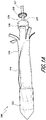
Figure 1A shows a side elevation view of an embodiment of a delivery system having pull wires. -
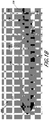
Figure 1B shows a photograph of a side elevation view of an embodiment of a delivery system having pull wires. -
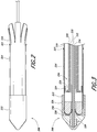
Figure 2 shows a side elevation view another embodiment of a delivery system having pull wires in a first state. -
Figure 3 illustrates a partial, cross-sectional view of the delivery system ofFigure 2 . -
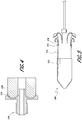
Figure 4 illustrates a partial cross-sectional view of an insert of the delivery system ofFigure 2 -
Figure 5 illustrates the delivery system ofFigure 2 in a second state. -
Figure 6 shows another embodiment of a delivery system having a compression member. -
Figure 7 illustrates a perspective view of a compression member and compression shaft of the delivery system ofFigure 6 . -
Figures 8-13 illustrate steps of a deployment method using the delivery system ofFigure 6 . - The present specification and drawings provide aspects and features of the disclosure in the context of several embodiments of replacement heart valves, delivery devices and methods that are configured for use in the vasculature of a patient, such as for replacement of natural heart valves in a patient. The devices, systems, and methods described herein can be used to transapically deliver a replacement heart valve to a mitral valve location. However, while these embodiments may be discussed in connection with replacing specific valves such as the patient's aortic or mitral valve, it is to be understood that the features and concepts discussed herein can be applied to products other than heart valve implants. For example, the controlled positioning, deployment, and securing features described herein can be applied to medical implants, for example other types of expandable prostheses, for use elsewhere in the body, such as within an artery, a vein, or other body cavities or locations. In addition, particular features of a valve, delivery device, etc. should not be taken as limiting, and features of any one embodiment discussed herein can be combined with features of other embodiments as desired and when appropriate.
- The implant or prosthesis can take any number of different forms. Example designs for a prosthesis are described in
U.S. Patent Nos. 8,403,983 ,8,414,644 , and8,652,203 ;U.S. Patent Publication Nos. 2011/0313515 andUS 2012/0215303 ;U.S. Application Nos. 14/197,590 ,14/197,639 14/197,690 U.S. Pat. App. Nos. 14/716,507 and14/628,034 - With reference first to the example shown in
Figures 1A-B which illustrates a delivery device orsystem 100, thedelivery system 100 can include an outer elongatehollow member 110 such as a sheath, a receivingmember 112 such as a nose cone, and one ormore pull wires 114. As shown in the illustrated example, the outer elongatehollow member 110 can have a distal end being positioned at least partially within the receiving member 112 (toward the left inFigures 1A-B ) and a proximal end being spaced away from the receiving member 112 (toward the right inFigures 1A-B ). As used to describe the components of the delivery system, "proximal" refers to a location of the component that is closer to the operator, and "distal" refers to a location of the component that is further from the operator. Based on the orientation of these figures, "proximal" would refer to a location to the right of the figures whereas "distal" would refer to a location to the left of the figures. The one ormore pull wires 114 can be attached to at least a portion of the outer elongatehollow member 110. Preferably, the one ormore pull wires 114 are attached to a proximal portion of the outer elongatehollow member 110. In some examples, the one ormore pull wires 114 are attached proximate to or at the proximal end of the outer elongatehollow member 110. As will be described in further detail below, the one ormore pull wires 114 can be used to collapse the outer elongatehollow member 110 to uncover at least part of a prosthesis, such as an expandable prosthesis, engaged on thedelivery system 100. - With continued reference to the example shown in
Figures 1A-B , thedelivery system 100 can include aninner retention assembly 116 designed to carry the expandable prosthesis to an in situ target location. Theinner retention assembly 116 can be designed to radially restrain a first end of the expandable prosthesis when the expandable prosthesis is mounted thereon with a second end of the expandable prosthesis extending proximally therefrom. In some embodiments, theinner retention assembly 116 can include aninner retention shaft 117, having a proximal and distal end, over which the expandable prosthesis can be mounted. In some embodiments, theinner retention shaft 117 can be used to carry and/or transport the expandable prosthesis to the in situ target location. As shown in the illustrated embodiment, theinner retention assembly 116 can include aninner retention member 118, such as an inner retention ring, attached to a distal end of theinner retention shaft 117. Theinner retention member 118 can include slots, grooves, clips, or other structures to engage at least a portion, if not the entirety, of the first end of the expandable prosthesis. For example, theinner retention member 118 may be used to engage tabs on the longitudinal struts 12 of the prosthesis 10 illustrated inFigure 1A ofU.S. Application No. 14/197,690 . In some embodiments, theinner retention assembly 116 can include anouter retention shaft 119 to which anouter retention member 120, such as an outer retention ring, can be attached at a distal end of theouter retention shaft 119. - As shown in the illustrated embodiment, the
inner retention member 118 and theouter retention member 120 can be moveable relative to each other and can cooperate to release the expandable prosthesis from theinner retention assembly 116. For example, theouter retention member 120 can be sized and shaped to cover theinner retention member 118 when the first end of the expandable prosthesis is engaged with theinner retention member 118. In this embodiment, theinner retention shaft 117 may be hollow so that theouter retention shaft 119 is slidable within theinner retention shaft 117. In embodiments where the expandable prosthesis is engaged with theinner retention member 118, use of theouter retention member 120 over theinner retention member 118 can restrain the expandable prosthesis from expanding radially outward from the longitudinal axis of the prosthesis. Upon movement of theouter retention member 120 relatively away from theinner retention member 118, theinner retention member 118 can be uncovered such that the expandable prosthesis can expand radially outward from the longitudinal axis of the prosthesis. In some embodiments, release of the first end of the expandable prosthesis from theinner retention assembly 116 wholly releases the expandable prosthesis from thedelivery system 100. Further details of an inner retention assembly are found inU.S. Patent No. US 8,652,203 referenced above. With continued reference to the embodiment shown inFigures 1A-B , the outer elongatehollow member 110 can be sized and shaped such that, when the expandable prosthesis is mounted on theinner retention assembly 116 and/or theinner retention shaft 117, the outer elongatehollow member 110 covers both the first and second ends of the expandable prosthesis to hold the prosthesis in a radially restrained configuration. The outer elongatehollow member 110 can be sized and shaped to be slidable over theinner retention assembly 116. With respect to the arrangement shown inFigures 1A-B , when the first end of a prosthesis is mounted on theinner retention assembly 116 and the second end of the prosthesis is positioned proximally of the first end, the outer elongatehollow member 110 would be moved proximally relative to theinner retention assembly 116 so that theinner retention assembly 116 and the prosthesis are covered by the outer elongatehollow member 110. The outer elongatehollow member 110 may comprise a flexible plastic material, and in some embodiments may be slitted at its proximal end to facilitate moving the outer elongatehollow member 110 over the prosthesis when the prosthesis is loaded onto the delivery system. The outer elongatehollow member 110 may comprise structures and/or materials that are generally resistant to radial expansion while being generally compliant to radial collapse. - With the
inner retention assembly 116 and the prosthesis covered by the outer elongatehollow member 110, the outer elongatehollow member 110 can be designed such that the outer elongatehollow member 110 can slide distally relative to theinner retention assembly 116 and/or theinner retention assembly 116 can slide proximally relative to the outer elongatehollow member 110. In some embodiments, distal movement of the outer elongatehollow member 110 relative to theinner retention assembly 116 can uncover at least the second end of the expandable prosthesis when the expandable prosthesis is mounted on theinner retention assembly 116. Distal movement of the outer elongatehollow member 110 relative to theinner retention assembly 116 and/or receivingmember 112 can cause longitudinal compression or collapse of at least a portion of the outer elongatehollow member 110 into the receivingmember 112. Accordingly, it should be understood that in some embodiments the outer elongatehollow member 110, or at least some portion thereof such as a proximal portion, can be formed from a generally deformable material. For example, the outer elongatehollow member 110 can be a collapsible polymer sheath. - With reference now to the embodiment shown in
Figures 2-5 which illustrates a delivery device orsystem 200, thedelivery system 200 can include components, structures, features and/or functionality which are the same as, or similar to, those described in connection with any of the delivery systems described herein such asdelivery system 100. Thedelivery system 200 can include a plurality of sheaths and/or shafts which can be sized and shaped to be slidable relative to each other. Accordingly, it should be understood that one or more of the plurality of shafts can be concentric with respect to another of the shafts to facilitate slidable movement of the shafts relative to each other. The plurality of shafts can be coupled to one or more other components of thedelivery system 200. - With reference first to the embodiment of
Figure 2 which illustrates a side elevation view of thedelivery system 200, thedelivery system 200 can include an outer elongatehollow member 210 such as a sheath, a receivingmember 212, and one ormore pull wires 214. Similar to outer elongatehollow member 110, the outer elongatehollow member 210 can have a proximal and distal end, with the receivingmember 212 positioned around the distal end of the outer elongatehollow member 210. The one ormore pull wires 214 can be attached to at least a portion of the outer elongatehollow member 210. As shown in the illustrated embodiment, the one or more pull wires can be attached to one or morecorresponding connector mechanisms 215 attached along a proximal portion of the outer elongatehollow member 210. In some embodiments,connector mechanism 215 can be a clip, suture, or fastener or other mechanical fastener as desired. In some embodiments,connector mechanism 215 can be a bonding agent such as an adhesive or weld directly formed on the outer elongatehollow member 210.Connector mechanisms 215 can be formed from a material different from that of the outer elongatehollow member 210 or can be formed from the same material. In some embodiments, the one ormore pull wires 214 are integral with the outer elongatehollow member 210. - With reference now to the embodiment shown in
Figure 3 which illustrates a partial cross-sectional view of thedelivery system 200, aninner retention assembly 216 of thedelivery system 200 is more clearly illustrated. Similar toinner retention assembly 116,inner retention assembly 216 can be designed to carry an expandable prosthesis to an in situ target location. Theinner retention assembly 216 can radially restrain a first end of the expandable prosthesis when the expandable prosthesis is mounted thereon with a second end of the expandable prosthesis extending proximally therefrom. - As shown in the illustrated embodiment, the
inner retention assembly 216 can include aninner retention shaft 218, having a proximal and distal end, over which the expandable prosthesis can be mounted. Aninner retention member 220, such as an inner retention ring, can be attached to a distal end of theinner retention shaft 218. In some embodiments, theinner retention shaft 218 andinner retention member 220 can form a monolithic unit. In other embodiments, theinner retention shaft 218 andinner retention member 220 can be separate components which can be attached after manufacture. Theinner retention assembly 216 can include anouter retention shaft 222 having a proximal end and a distal end to which anouter retention member 224, such as an outer retention ring, can be attached. Theinner retention member 220 and theouter retention member 224 can be moveable relative to each other and can cooperate to release the expandable prosthesis from theinner retention assembly 216. For example, as shown in the illustrated embodiment, theouter retention member 224 can be sized and shaped to cover theinner retention member 220 when the first end of the expandable prosthesis is engaged with theinner retention member 220. Upon movement of theouter retention member 224 relatively away from theinner retention member 220, theinner retention member 220 can be uncovered such that the expandable prosthesis can expand radially outward from the longitudinal axis of the prosthesis. In some embodiments, release of the first end of the expandable prosthesis from theinner retention assembly 216 wholly releases the expandable prosthesis from thedelivery system 200. - With continued reference to the embodiment shown in
Figure 3 , theinner retention member 220 and theouter retention member 224 can be moved relative to each other via moving either theinner retention shaft 218 relative to theouter retention shaft 222 or by moving theouter retention shaft 222 relative to theinner retention shaft 218. Accordingly, theouter retention shaft 222 can be sized and shaped to be slidable relative to theinner retention shaft 218. For example, as shown in the illustrated embodiment, theouter retention shaft 222 can be sized to be slidable within theinner retention shaft 218. - With continued reference to the embodiment shown in
Figures 3 and4 , the receivingmember 212 can include anose cone 226 and aninsert 228. Theinsert 228 can engage thenose cone 226 via a threadedend 229 as illustrated or via any other suitable mechanism such as a snap-fit connection, clips, separate fasteners such as screws, bolts, rivets and the like, bonding agents such as an adhesive, welds or other bonding techniques, any other attachment mechanism or technique as desired, or any combination of these mechanisms and techniques. Theinsert 228 can include apath 230 through which the one ormore pull wires 224 can be inserted and guided. Thepath 230 can be curved and, in some embodiments, have a "U" shape. As shown in the illustrated embodiment, the one ormore pull wires 224 can extend from the correspondingconnector mechanisms 215, pass through thepath 230 of the receivingmember 212 and pass through and out of theinner retention assembly 216. Accordingly, proximal movement of theend 232 of the one ormore pull wires 224 can result in distal movement of the end of the one ormore pull wires 224 attached to correspondingconnector mechanisms 215. As a result, retraction of theend 232 ofpull wire 224 in a proximal direction can cause the proximal portion of the outer elongatehollow member 210 to be moved distally and relatively toward the receivingmember 212 to which the outer elongatehollow member 210 is attached. As shown in the embodiment ofFigure 5 , the outer elongatehollow member 210 can longitudinally compress or collapsed into the receivingmember 212. - With reference back to the embodiment shown in
Figure 3 , thedelivery system 200 can include anose cone shaft 234 having a proximal and distal end. Thenose cone 226 and/or insert 228 can be attached to a distal end of thenose cone shaft 234. Thenose cone shaft 234 can be sized and shaped to be moveable relative to theinner retention assembly 216. For example, as shown in the illustrated embodiment, thenose cone shaft 234 can be sized and shaped to be slidable within theouter retention shaft 222. Thenose cone shaft 234 can also be sized and shaped to allow a guidewire to pass therethrough. - With reference now to the embodiment shown in
Figures 6-13 which illustrates a delivery device orsystem 300, thedelivery system 300 can include components, structures, features and/or functionality which are the same as, or similar to, those described in connection with any of the delivery systems described herein such asdelivery systems delivery system 300 can include a plurality of sheaths and/or shafts which can be sized and shaped to be slidable relative to each other. Accordingly, it should be understood that one or more of the plurality of shafts can be concentric with respect to another of the shafts to facilitate slidable movement of the shafts relative to each other. The plurality of shafts can be coupled to one or more other components of thedelivery system 300. - With reference first to the embodiment of
Figure 6 , thedelivery system 300 can include an outer elongatehollow member 310 such as a sheath and a receivingmember 312. Similar to outer elongatehollow member 210, the outer elongatehollow member 310 can have a proximal and distal end, with the receivingmember 312 positioned around the distal end of the outer elongatehollow member 310. Similar todelivery system 200, thedelivery system 300 can include aninner retention assembly 316 which can be designed to carry an expandable prosthesis to an in situ target location. Theinner retention assembly 316 can radially restrain a first end of the expandable prosthesis when the expandable prosthesis is mounted thereon with a second end of the expandable prosthesis extending proximally therefrom. - As shown in the illustrated embodiment, the
inner retention assembly 316 can include aninner retention shaft 318, aninner retention member 320, anouter retention shaft 322 and anouter retention member 324 which can have structures, features and/or functionality which are the same as, or similar to, those ofinner retention shaft 218,inner retention member 220,outer retention shaft 222 andouter retention member 224 respectively. Moreover, the receivingmember 312 can include anose cone 326, aninsert 328, and anose cone shaft 334.Nose cone 326, insert 328 andnose cone shaft 334 can have structures, features and/or functionality which are the same as, or similar to, those ofnose cone 226, insert 228, andnose cone shaft 334 respectively. For purposes of brevity, reference should be made to the discussion of these components above in connection withFigures 2-5 . As shown in the illustrated embodiment, insert 328 does not include a guide path. - With continued reference to the embodiment shown in
Figures 6 and 7 ,delivery system 300 includes acompression member 330, which is a squash plate, designed to compress or collapse the outer elongatehollow member 310. Thecompression member 330 can have a tapered or non-taperedproximal side 331 and a tootheddistal side 333 having a plurality of slots or teeth for engaging an inner surface the outer elongatehollow member 310. Thecompression member 330 can be attached to the distal end of acompression shaft 332. Thecompression member 330 can be moveable relative to theinner retention assembly 316 and/or receivingmember 312 to compress or collapse the outer elongatehollow member 310. As shown in the illustrated embodiment, thecompression member 330 can be moved relative to theinner retention assembly 316 and/or the receivingmember 312 via movement of one or more of theinner retention shaft 318,outer retention shaft 322, andnose cone shaft 334 relative to thecompression shaft 332. As shown in the illustrated embodiment, thecompression shaft 332 can be sized and shaped to be slidable within theinner retention assembly 316. - The example of
Figures 8-13 illustrates steps of a method of operating thedelivery system 300 and releasing a prosthesis, such as an intralumenal frame assembly, to intralumenal tissue at an in situ target location. The steps of this method can be carried out while the prosthesis is in a radially compacted state within thedelivery system 300. In some embodiments, the longitudinal axis of the prosthesis, which runs between the first and second ends of the prosthesis, can be parallel to and/or concentric with the longitudinal axis of one or more shafts of thedelivery system 300. The steps of this method can be used to transapically deliver a replacement heart valve to a mitral valve location. - With reference first to the step of
Figure 8 , thedelivery system 300 is shown with the receivingmember 312, theinner retention assembly 316, and thecompression member 330 in a second configuration. In this second configuration, theinner retention assembly 316 andcompression member 330 are spaced away from the receivingmember 312 such that agap 336 is formed between thecompression member 330 and the receivingmember 312. These components can be transitioned from the first configuration illustrated inFigure 6 to the second configuration illustrated inFigure 8 via movement of thecompression member 330 and theinner retention assembly 316 relatively away from the receivingmember 312. For example, the receivingmember 312 can be advanced distally relative to thecompression member 330 and theinner retention assembly 316. Likewise, thecompression member 330 and theinner retention assembly 316 can be retracted proximally relative to the receivingmember 312. Either of these movements may cause a prosthesis within the outer elongatehollow member 310 to become at least partially uncovered. For example, a second end of a prosthesis may be uncovered and be allowed to radially expand due to either of these movements, with the first end of the prosthesis still restrained by theinner retention assembly 316. - With reference next to the step of
Figure 9 , thedelivery system 300 is shown with the receivingmember 312, theinner retention assembly 316, and thecompression member 330 back in the first configuration. These components can be transitioned from the second configuration back to the first configuration via movement of thecompression member 330 and theinner retention assembly 316 relatively toward the receivingmember 312. For example, the receivingmember 312 can be retracted proximally relative to thecompression member 330 and theinner retention assembly 316. Likewise, thecompression member 330 and theinner retention assembly 316 can be advanced distally relative to the receivingmember 312. - As a result of this relative movement of the
compression member 330 and theinner retention assembly 316 towards the receivingmember 312, the outer elongatehollow member 310 is moved relatively toward the receivingmember 312. Without being limited to a particular theory of operation, this movement can result from frictional engagement between thecompression member 330 and/or theinner retention assembly 316 with the outer elongatehollow member 310. As a result of movement of the outer elongatehollow member 310, the outer elongatehollow member 310 can be compressed or collapsed into thegap 336 between the receivingmember 312 and thecompression member 330. As shown in the illustrated embodiment, the outer elongatehollow member 310 has slightly folded within thisgap 336. Once the movement illustrated inFigure 9 has been achieved, a prosthesis covered by the outer elongatehollow member 310 may be further exposed and may further radially expand. - With reference next to the step of
Figure 10 , thedelivery system 300 is shown with the receivingmember 312, theinner retention assembly 316, and thecompression member 330 in a third configuration. These components can be transitioned from the first configuration to the third configuration via movement of theinner retention assembly 316 relatively away from the receivingmember 312 while maintaining thecompression member 330 generally in the same position relative to the receivingmember 312. For example, the receivingmember 312 andcompression member 330 can be advanced distally relative to theinner retention assembly 316. Likewise, theinner retention assembly 316 can be retracted proximally relative to the receivingmember 312 and thecompression member 330. Either of these movements may further uncover the prosthesis and permit it to radially expand. - Due to the
compression member 330 remaining in contact with folds of the outer elongatehollow member 310, the outer elongatehollow member 310 remains generally in the same compressed or collapsed configuration as theinner retention assembly 316 is moved relatively away from the receivingmember 312. Accordingly, it should be noted that the outer elongatehollow member 310 remains in generally the same compressed or collapsed state as when the components were in the previous configuration (as shown inFigure 9 ). - With reference next to the step of
Figure 11 , thedelivery system 300 is shown with the receivingmember 312, theinner retention assembly 316, and thecompression member 330 back in the second configuration. These components can be transitioned from the third configuration back to the second configuration via movement of thecompression member 330 relatively away from the receivingmember 312 while maintaining theinner retention assembly 316 generally in the same position relative to the receivingmember 312. For example, thecompression member 330 can be retracted proximally relative to the receivingmember 312 and theinner retention assembly 316. Likewise, the receivingmember 312 and theinner retention assembly 316 can be advanced distally relative to thecompression member 330. - Due in part to the tapered shape of the
compression member 330 on the proximal side and contact between theinner retention assembly 316 and the outer elongatehollow member 310, the outer elongatehollow member 310 remains generally in the same compressed or collapsed configuration as when the components were in the previous configurations (as shown inFigures 9 and10 ). It should be noted that while the receivingmember 312, theinner retention assembly 316 and thecompression member 330 are in a similar position to that shown inFigure 8 , movement of these components from the second configuration to the first configuration, from the first configuration to the third configuration, and from the third configuration back to the second configuration causes compression or collapse of the outer elongatehollow member 310. This procedure can be repeated until the outer elongatehollow member 310 has been moved sufficiently toward the receivingmember 312 to expose at least a portion, if not the entirety, of the prosthesis contained on thedelivery system 300. In order to facilitate compression or collapse of the outer elongatehollow member 310, the outer elongatehollow member 310 can be manufactured from a material and/or have a structure with reduced column strength. - With reference next to the step of
Figure 12 , thedelivery device 300 is shown in the second configuration with the outer elongatehollow member 310 having been moved sufficiently towards the receivingmember 312. At this point, the prosthesis may be entirely or almost entirely uncovered other than its first end being retained by theinner retention assembly 316. With reference next to the step ofFigure 13 , theinner retention assembly 316 can be actuated to release the prosthesis from thedelivery system 300. As shown in the illustrated embodiment, release of the prosthesis can be achieved by moving theinner retention member 320 relatively away from theouter retention member 324. - It will be understood that the delivery devices, such as
delivery devices U.S. Patent Nos. 8,414,644 and8,652,203 . For example, the nose cone can include a prosthesis retention mechanism such as an inner retention ring that can be used to engage with the prosthesis as may be described in these applications. Struts or other parts of a prosthesis can be engaged with the inner retention ring and the nose cone can cover both the prosthesis and the inner retention ring to secure the prosthesis on thedelivery devices - Although this invention has been disclosed in the context of certain preferred embodiments and examples, it will be understood by those skilled in the art that the present invention extends beyond the specifically disclosed embodiments to other alternative embodiments and/or uses of the invention and obvious modifications, as long as the resulting embodiment falls within the scope of the invention as claimed. The scope of the present invention herein disclosed should not be limited by the particular disclosed embodiments described above, but should be determined only by a fair reading of the claims that follow.
Claims (8)
- A delivery system (300) for controlled deployment of an expandable prosthesis, the delivery system (300) comprising:an inner retention assembly (316) comprising an inner elongate member (318) having a proximal end and a distal end configured to carry the expandable prosthesis to an in situ target locationan outer elongate hollow member (310) having a proximal end and a distal end that is slidable over the inner retention assembly (316), the outer elongate hollow member (310) configured to cover the first and second ends of the expandable prosthesis when the expandable prosthesis is mounted over the inner elongate member (318); andwherein the outer elongate hollow member (310) is moveable in a distal direction relative to the inner retention assembly (316) to uncover at least the second end of the expandable prosthesis when the expandable prosthesis is mounted over the inner elongate member (318), wherein distal movement of the outer elongate hollow member (310) relative to the inner retention assembly (316) causes longitudinal collapse of at least a portion of the outer elongate hollow member (310),characterized in thatthe inner retention assembly (316) is configured to radially restrain a first end of the expandable prosthesis when the expandable prosthesis is mounted over the inner elongate member (318) with the second end of the expandable prosthesis positioned proximally of the first end,wherein the delivery system (300) further comprises a receiving member (312) provided at the distal end of the outer elongate hollow member (310), wherein the distal end of the outer elongate hollow member (310) is positioned within the receiving member (312) and the proximal end of the outer elongate hollow member (310) is spaced proximally away from the receiving member (312) and a squash plate (330) configured to cause longitudinal collapse of the outer member into the receiving member (312).
- The delivery system (300) of Claim 1, wherein the inner retention assembly (316) comprises an inner retention ring (320) at the distal end of the inner elongate member (318) configured to engage the first end of the expandable prosthesis.
- The delivery system (300) of Claim 2, wherein the inner retention assembly (316) further comprises an outer retention ring (324) configured to cover the inner retention ring (320) when the inner retention ring (320) engages the first end of the expandable prosthesis.
- The delivery system (300) of any one of the preceding claims, wherein the receiving member (312) comprises a nose cone (326).
- The delivery system (300) of Claim 4, further comprising a nose cone shaft (334) slidable within the inner elongate member (318), wherein the nose cone (326) is connected to a distal end of the nose cone shaft (334).
- The delivery system (300) of Claim 1, further comprising a compression shaft (332) slidable within the inner retention assembly (316), wherein the squash plate (330) is connected to a distal end of the compression shaft (332).
- The delivery system (300) of any one of the preceding claims, wherein the outer elongate hollow member (310) comprises a collapsible polymer sheath.
- The delivery system (300) of any one of the preceding claims, further comprising an expandable prosthesis having a first end radially restrained by the inner retention assembly (316) and wherein the first end and the second end of the expandable prosthesis are covered by the outer elongate hollow member (310).
Applications Claiming Priority (2)
| Application Number | Priority Date | Filing Date | Title |
|---|---|---|---|
| US201462004610P | 2014-05-29 | 2014-05-29 | |
| PCT/US2015/032978 WO2015184138A1 (en) | 2014-05-29 | 2015-05-28 | Prosthesis, delivery device and methods of use |
Publications (2)
| Publication Number | Publication Date |
|---|---|
| EP3134033A1 EP3134033A1 (en) | 2017-03-01 |
| EP3134033B1 true EP3134033B1 (en) | 2018-04-04 |
Family
ID=53540831
Family Applications (1)
| Application Number | Title | Priority Date | Filing Date |
|---|---|---|---|
| EP15736330.0A Active EP3134033B1 (en) | 2014-05-29 | 2015-05-28 | Prosthesis and delivery device |
Country Status (3)
| Country | Link |
|---|---|
| US (1) | US9687345B2 (en) |
| EP (1) | EP3134033B1 (en) |
| WO (1) | WO2015184138A1 (en) |
Cited By (15)
| Publication number | Priority date | Publication date | Assignee | Title |
|---|---|---|---|---|
| US10856984B2 (en) | 2017-08-25 | 2020-12-08 | Neovasc Tiara Inc. | Sequentially deployed transcatheter mitral valve prosthesis |
| US10940001B2 (en) | 2012-05-30 | 2021-03-09 | Neovasc Tiara Inc. | Methods and apparatus for loading a prosthesis onto a delivery system |
| US11311376B2 (en) | 2019-06-20 | 2022-04-26 | Neovase Tiara Inc. | Low profile prosthetic mitral valve |
| US11357622B2 (en) | 2016-01-29 | 2022-06-14 | Neovase Tiara Inc. | Prosthetic valve for avoiding obstruction of outflow |
| US11389291B2 (en) | 2013-04-04 | 2022-07-19 | Neovase Tiara Inc. | Methods and apparatus for delivering a prosthetic valve to a beating heart |
| US11413139B2 (en) | 2011-11-23 | 2022-08-16 | Neovasc Tiara Inc. | Sequentially deployed transcatheter mitral valve prosthesis |
| US11419720B2 (en) | 2010-05-05 | 2022-08-23 | Neovasc Tiara Inc. | Transcatheter mitral valve prosthesis |
| US11464631B2 (en) | 2016-11-21 | 2022-10-11 | Neovasc Tiara Inc. | Methods and systems for rapid retraction of a transcatheter heart valve delivery system |
| US11491006B2 (en) | 2019-04-10 | 2022-11-08 | Neovasc Tiara Inc. | Prosthetic valve with natural blood flow |
| US11497602B2 (en) | 2012-02-14 | 2022-11-15 | Neovasc Tiara Inc. | Methods and apparatus for engaging a valve prosthesis with tissue |
| US11602429B2 (en) | 2019-04-01 | 2023-03-14 | Neovasc Tiara Inc. | Controllably deployable prosthetic valve |
| US11737872B2 (en) | 2018-11-08 | 2023-08-29 | Neovasc Tiara Inc. | Ventricular deployment of a transcatheter mitral valve prosthesis |
| US11779742B2 (en) | 2019-05-20 | 2023-10-10 | Neovasc Tiara Inc. | Introducer with hemostasis mechanism |
| US11998447B2 (en) | 2019-03-08 | 2024-06-04 | Neovasc Tiara Inc. | Retrievable prosthesis delivery system |
| US12109111B2 (en) | 2015-12-15 | 2024-10-08 | Neovasc Tiara Inc. | Transseptal delivery system |
Families Citing this family (45)
| Publication number | Priority date | Publication date | Assignee | Title |
|---|---|---|---|---|
| US7704277B2 (en) | 2004-09-14 | 2010-04-27 | Edwards Lifesciences Ag | Device and method for treatment of heart valve regurgitation |
| CA2629534C (en) | 2005-11-10 | 2015-02-24 | Arshad Quadri | Balloon-expandable, self-expanding, vascular prosthesis connecting stent |
| US20090276040A1 (en) | 2008-05-01 | 2009-11-05 | Edwards Lifesciences Corporation | Device and method for replacing mitral valve |
| WO2010121076A2 (en) | 2009-04-15 | 2010-10-21 | Cardiaq Valve Technologies, Inc. | Vascular implant and delivery system |
| EP4035623A1 (en) | 2009-04-29 | 2022-08-03 | Edwards Lifesciences Corporation | Apparatus and method for replacing a diseased cardiac valve |
| US8449599B2 (en) | 2009-12-04 | 2013-05-28 | Edwards Lifesciences Corporation | Prosthetic valve for replacing mitral valve |
| US8870950B2 (en) | 2009-12-08 | 2014-10-28 | Mitral Tech Ltd. | Rotation-based anchoring of an implant |
| US20110224785A1 (en) | 2010-03-10 | 2011-09-15 | Hacohen Gil | Prosthetic mitral valve with tissue anchors |
| US11653910B2 (en) | 2010-07-21 | 2023-05-23 | Cardiovalve Ltd. | Helical anchor implantation |
| EP3459500B1 (en) | 2010-09-23 | 2020-09-16 | Edwards Lifesciences CardiAQ LLC | Replacement heart valves and delivery devices |
| WO2013021374A2 (en) | 2011-08-05 | 2013-02-14 | Mitraltech Ltd. | Techniques for percutaneous mitral valve replacement and sealing |
| US8852272B2 (en) | 2011-08-05 | 2014-10-07 | Mitraltech Ltd. | Techniques for percutaneous mitral valve replacement and sealing |
| EP3417813B1 (en) | 2011-08-05 | 2020-05-13 | Cardiovalve Ltd | Percutaneous mitral valve replacement |
| WO2014115149A2 (en) | 2013-01-24 | 2014-07-31 | Mitraltech Ltd. | Ventricularly-anchored prosthetic valves |
| US9439763B2 (en) | 2013-02-04 | 2016-09-13 | Edwards Lifesciences Corporation | Prosthetic valve for replacing mitral valve |
| US10583002B2 (en) | 2013-03-11 | 2020-03-10 | Neovasc Tiara Inc. | Prosthetic valve with anti-pivoting mechanism |
| US20140277427A1 (en) | 2013-03-14 | 2014-09-18 | Cardiaq Valve Technologies, Inc. | Prosthesis for atraumatically grasping intralumenal tissue and methods of delivery |
| US9532870B2 (en) | 2014-06-06 | 2017-01-03 | Edwards Lifesciences Corporation | Prosthetic valve for replacing a mitral valve |
| WO2016016899A1 (en) | 2014-07-30 | 2016-02-04 | Mitraltech Ltd. | Articulatable prosthetic valve |
| CN106852115A (en) | 2014-09-28 | 2017-06-13 | 卡迪欧凯尼迪克斯公司 | device for treating cardiac insufficiency |
| ES2989081T3 (en) | 2014-11-26 | 2024-11-25 | Edwards Lifesciences Corp | Transcatheter prosthetic heart valve and delivery system |
| CA3162308A1 (en) | 2015-02-05 | 2016-08-11 | Cardiovalve Ltd. | Prosthetic valve with axially-sliding frames |
| US9974651B2 (en) | 2015-02-05 | 2018-05-22 | Mitral Tech Ltd. | Prosthetic valve with axially-sliding frames |
| EP3271000B1 (en) | 2015-03-20 | 2020-06-17 | Cardiokinetix, Inc. | Systems for delivering an implantable device |
| US10531866B2 (en) | 2016-02-16 | 2020-01-14 | Cardiovalve Ltd. | Techniques for providing a replacement valve and transseptal communication |
| US10758350B2 (en) * | 2016-06-06 | 2020-09-01 | Medtronic Vascular, Inc. | Transcatheter prosthetic heart valve delivery system with protective feature |
| US10350062B2 (en) | 2016-07-21 | 2019-07-16 | Edwards Lifesciences Corporation | Replacement heart valve prosthesis |
| US20190231525A1 (en) | 2016-08-01 | 2019-08-01 | Mitraltech Ltd. | Minimally-invasive delivery systems |
| EP4523659A3 (en) | 2016-08-10 | 2025-06-04 | Cardiovalve Ltd. | Prosthetic valve with concentric frames |
| US10646338B2 (en) | 2017-06-02 | 2020-05-12 | Twelve, Inc. | Delivery systems with telescoping capsules for deploying prosthetic heart valve devices and associated methods |
| US10537426B2 (en) | 2017-08-03 | 2020-01-21 | Cardiovalve Ltd. | Prosthetic heart valve |
| US11246704B2 (en) | 2017-08-03 | 2022-02-15 | Cardiovalve Ltd. | Prosthetic heart valve |
| US11793633B2 (en) | 2017-08-03 | 2023-10-24 | Cardiovalve Ltd. | Prosthetic heart valve |
| US10888421B2 (en) | 2017-09-19 | 2021-01-12 | Cardiovalve Ltd. | Prosthetic heart valve with pouch |
| US12064347B2 (en) | 2017-08-03 | 2024-08-20 | Cardiovalve Ltd. | Prosthetic heart valve |
| US10575948B2 (en) | 2017-08-03 | 2020-03-03 | Cardiovalve Ltd. | Prosthetic heart valve |
| US12458493B2 (en) | 2017-09-19 | 2025-11-04 | Cardiovalve Ltd. | Prosthetic heart valve and delivery systems and methods |
| GB201720803D0 (en) | 2017-12-13 | 2018-01-24 | Mitraltech Ltd | Prosthetic Valve and delivery tool therefor |
| GB201800399D0 (en) | 2018-01-10 | 2018-02-21 | Mitraltech Ltd | Temperature-control during crimping of an implant |
| WO2019147846A2 (en) | 2018-01-25 | 2019-08-01 | Edwards Lifesciences Corporation | Delivery system for aided replacement valve recapture and repositioning post- deployment |
| WO2020210794A1 (en) | 2019-04-12 | 2020-10-15 | W. L. Gore & Associates, Inc. | Valve with multi-part frame and associated resilient bridging features |
| EP3958792B1 (en) | 2019-04-23 | 2024-02-14 | Edwards Lifesciences Corporation | Motorized implant delivery system |
| US12357459B2 (en) | 2020-12-03 | 2025-07-15 | Cardiovalve Ltd. | Transluminal delivery system |
| EP4247297A1 (en) | 2020-12-18 | 2023-09-27 | Edwards Lifesciences Corporation | Storage jar assembly for aprosthetic heart valve |
| US20230149164A1 (en) * | 2021-11-17 | 2023-05-18 | Neovasc Tiara Inc. | Systems and methods for deploying and retrieving a prosthesis |
Family Cites Families (183)
| Publication number | Priority date | Publication date | Assignee | Title |
|---|---|---|---|---|
| US4378224A (en) | 1980-09-19 | 1983-03-29 | Nimni Marcel E | Coating for bioprosthetic device and method of making same |
| FR2523810B1 (en) | 1982-03-23 | 1988-11-25 | Carpentier Alain | ORGANIC GRAFT FABRIC AND PROCESS FOR ITS PREPARATION |
| IT1194556B (en) | 1983-03-11 | 1988-09-22 | Carlo Rebuffat | CURVED BRANCH ENTER SWITCH FOR THE AUTOMATIC EXECUTION OF TOBACCO BAG SUTURES ON CABLE VISCERS |
| US4582181A (en) | 1983-08-12 | 1986-04-15 | Advanced Cardiovascular Systems, Inc. | Steerable dilatation catheter |
| US4753652A (en) | 1984-05-04 | 1988-06-28 | Children's Medical Center Corporation | Biomaterial implants which resist calcification |
| US4573470A (en) | 1984-05-30 | 1986-03-04 | Advanced Cardiovascular Systems, Inc. | Low-profile steerable intraoperative balloon dilitation catheter |
| US4553974A (en) | 1984-08-14 | 1985-11-19 | Mayo Foundation | Treatment of collagenous tissue with glutaraldehyde and aminodiphosphonate calcification inhibitor |
| US4944740A (en) | 1984-09-18 | 1990-07-31 | Medtronic Versaflex, Inc. | Outer exchange catheter system |
| US5125895A (en) | 1986-07-22 | 1992-06-30 | Medtronic Versaflex, Inc. | Steerable catheter |
| US6071273A (en) | 1988-02-29 | 2000-06-06 | Scimed Life Systems, Inc. | Fixed wire dilatation balloon catheter |
| US5059186A (en) | 1988-03-07 | 1991-10-22 | Vitaphore Corporation | Percutaneous access device |
| US5318587A (en) | 1989-08-25 | 1994-06-07 | C. R. Bard, Inc. | Pleated balloon dilatation catheter and method of use |
| US6033378A (en) | 1990-02-02 | 2000-03-07 | Ep Technologies, Inc. | Catheter steering mechanism |
| US5766151A (en) | 1991-07-16 | 1998-06-16 | Heartport, Inc. | Endovascular system for arresting the heart |
| US5795325A (en) | 1991-07-16 | 1998-08-18 | Heartport, Inc. | Methods and apparatus for anchoring an occluding member |
| US5370685A (en) | 1991-07-16 | 1994-12-06 | Stanford Surgical Technologies, Inc. | Endovascular aortic valve replacement |
| US5571215A (en) | 1993-02-22 | 1996-11-05 | Heartport, Inc. | Devices and methods for intracardiac procedures |
| DE4137218C1 (en) | 1991-11-13 | 1993-02-11 | Heidmueller, Harald, 5000 Koeln, De | |
| US5417700A (en) | 1992-03-30 | 1995-05-23 | Thomas D. Egan | Automatic suturing and ligating device |
| US5425737A (en) | 1992-04-08 | 1995-06-20 | American Cyanamid Co. | Surgical purse string suturing instrument and method |
| US5368601A (en) | 1992-04-30 | 1994-11-29 | Lasersurge, Inc. | Trocar wound closure device |
| US5188636A (en) | 1992-05-07 | 1993-02-23 | Ethicon, Inc. | Purse string suture instrument |
| US6336938B1 (en) | 1992-08-06 | 2002-01-08 | William Cook Europe A/S | Implantable self expanding prosthetic device |
| US5364408A (en) | 1992-09-04 | 1994-11-15 | Laurus Medical Corporation | Endoscopic suture system |
| CA2106127A1 (en) | 1992-09-23 | 1994-03-24 | Peter W.J. Hinchliffe | Instrument for closing trocar puncture wounds |
| US5304184A (en) | 1992-10-19 | 1994-04-19 | Indiana University Foundation | Apparatus and method for positive closure of an internal tissue membrane opening |
| DE4237194A1 (en) | 1992-11-04 | 1994-05-05 | Bosch Gmbh Robert | Device for determining the speed gradient |
| US6283127B1 (en) | 1992-12-03 | 2001-09-04 | Wesley D. Sterman | Devices and methods for intracardiac procedures |
| US5718725A (en) | 1992-12-03 | 1998-02-17 | Heartport, Inc. | Devices and methods for intracardiac procedures |
| US5417699A (en) | 1992-12-10 | 1995-05-23 | Perclose Incorporated | Device and method for the percutaneous suturing of a vascular puncture site |
| US5972030A (en) | 1993-02-22 | 1999-10-26 | Heartport, Inc. | Less-invasive devices and methods for treatment of cardiac valves |
| US5797960A (en) | 1993-02-22 | 1998-08-25 | Stevens; John H. | Method and apparatus for thoracoscopic intracardiac procedures |
| US5728151A (en) | 1993-02-22 | 1998-03-17 | Heartport, Inc. | Intercostal access devices for less-invasive cardiovascular surgery |
| US6346074B1 (en) | 1993-02-22 | 2002-02-12 | Heartport, Inc. | Devices for less invasive intracardiac interventions |
| US5306234A (en) | 1993-03-23 | 1994-04-26 | Johnson W Dudley | Method for closing an atrial appendage |
| US5374275A (en) | 1993-03-25 | 1994-12-20 | Synvasive Technology, Inc. | Surgical suturing device and method of use |
| EP0711130B1 (en) | 1993-07-30 | 2002-11-06 | Boston Scientific Limited | Catheter with bendable tip assembly |
| US5527322A (en) | 1993-11-08 | 1996-06-18 | Perclose, Inc. | Device and method for suturing of internal puncture sites |
| US5350361A (en) | 1993-11-10 | 1994-09-27 | Medtronic, Inc. | Tri-fold balloon for dilatation catheter and related method |
| US5431666A (en) | 1994-02-24 | 1995-07-11 | Lasersurge, Inc. | Surgical suture instrument |
| US5458572A (en) | 1994-07-01 | 1995-10-17 | Boston Scientific Corp. | Catheter with balloon folding into predetermined configurations and method of manufacture |
| US5599305A (en) | 1994-10-24 | 1997-02-04 | Cardiovascular Concepts, Inc. | Large-diameter introducer sheath having hemostasis valve and removable steering mechanism |
| US5534007A (en) * | 1995-05-18 | 1996-07-09 | Scimed Life Systems, Inc. | Stent deployment catheter with collapsible sheath |
| US6562052B2 (en) | 1995-08-24 | 2003-05-13 | Sutura, Inc. | Suturing device and method |
| US5860990A (en) | 1995-08-24 | 1999-01-19 | Nr Medical, Inc. | Method and apparatus for suturing |
| US6117144A (en) | 1995-08-24 | 2000-09-12 | Sutura, Inc. | Suturing device and method for sealing an opening in a blood vessel or other biological structure |
| GB9522332D0 (en) | 1995-11-01 | 1996-01-03 | Biocompatibles Ltd | Braided stent |
| AUPN766296A0 (en) | 1996-01-22 | 1996-02-15 | Endogad Research Pty Limited | Trocar and introducing kit |
| AUPN775296A0 (en) | 1996-01-25 | 1996-02-22 | Endogad Research Pty Limited | Directional catheter |
| US5843161A (en) | 1996-06-26 | 1998-12-01 | Cordis Corporation | Endoprosthesis assembly for percutaneous deployment and method of deploying same |
| US5820631A (en) | 1996-08-01 | 1998-10-13 | Nr Medical, Inc. | Device and method for suturing tissue adjacent to a blood vessel |
| US5968068A (en) | 1996-09-12 | 1999-10-19 | Baxter International Inc. | Endovascular delivery system |
| US5792172A (en) | 1996-12-23 | 1998-08-11 | Isostent, Inc. | Multifold balloon for stent deployment |
| EP0850607A1 (en) | 1996-12-31 | 1998-07-01 | Cordis Corporation | Valve prosthesis for implantation in body channels |
| US6506339B1 (en) | 1997-02-10 | 2003-01-14 | Biomedical Design, Inc. | Method of sterilization |
| US5891159A (en) | 1997-05-02 | 1999-04-06 | Cardiothoratic Systems, Inc. | Automatic purse string suture device |
| US6004328A (en) * | 1997-06-19 | 1999-12-21 | Solar; Ronald J. | Radially expandable intraluminal stent and delivery catheter therefore and method of using the same |
| WO1999000059A1 (en) | 1997-06-27 | 1999-01-07 | The Trustees Of Columbia University In The City Of New York | Method and apparatus for circulatory valve repair |
| KR100235464B1 (en) | 1997-07-19 | 1999-12-15 | 성재갑 | Process for preparing abs resins |
| US5928131A (en) | 1997-11-26 | 1999-07-27 | Vascor, Inc. | Magnetically suspended fluid pump and control system |
| US6251092B1 (en) | 1997-12-30 | 2001-06-26 | Medtronic, Inc. | Deflectable guiding catheter |
| WO1999040868A1 (en) | 1998-02-13 | 1999-08-19 | Ventrica, Inc. | Methods and devices providing transmyocardial blood flow to the arterial vascular system of the heart |
| US5972005A (en) | 1998-02-17 | 1999-10-26 | Advanced Cardiovascular Systems, Ind. | Wound closure assembly and method of use |
| US6174327B1 (en) * | 1998-02-27 | 2001-01-16 | Scimed Life Systems, Inc. | Stent deployment apparatus and method |
| US7569062B1 (en) | 1998-07-15 | 2009-08-04 | St. Jude Medical, Inc. | Mitral and tricuspid valve repair |
| US6260552B1 (en) | 1998-07-29 | 2001-07-17 | Myocor, Inc. | Transventricular implant tools and devices |
| US6143004A (en) | 1998-08-18 | 2000-11-07 | Atrion Medical Products, Inc. | Suturing device |
| US6013092A (en) | 1998-08-18 | 2000-01-11 | Baxter International Inc. | Folding of catheter-mounted balloons to facilitate non-rotational radial expansion of intraluminal devices |
| US6001056A (en) | 1998-11-13 | 1999-12-14 | Baxter International Inc. | Smooth ventricular assist device conduit |
| US6591472B1 (en) | 1998-12-08 | 2003-07-15 | Medtronic, Inc. | Multiple segment catheter and method of fabrication |
| US6558418B2 (en) | 1999-01-26 | 2003-05-06 | Edwards Lifesciences Corporation | Flexible heart valve |
| US6425916B1 (en) | 1999-02-10 | 2002-07-30 | Michi E. Garrison | Methods and devices for implanting cardiac valves |
| DE19907646A1 (en) | 1999-02-23 | 2000-08-24 | Georg Berg | Valve for blood vessels uses flap holders and counterpart holders on stent to latch together in place and all channeled for guide wire. |
| US6146325A (en) | 1999-06-03 | 2000-11-14 | Arrow International, Inc. | Ventricular assist device |
| WO2001008050A1 (en) | 1999-07-21 | 2001-02-01 | Queryobject Systems Corporation | Database management system |
| US6358258B1 (en) | 1999-09-14 | 2002-03-19 | Abbott Laboratories | Device and method for performing end-to-side anastomosis |
| US6592602B1 (en) | 1999-10-08 | 2003-07-15 | General Surgical Innovations, Inc. | Balloon dissection apparatus |
| WO2001030245A1 (en) | 1999-10-26 | 2001-05-03 | H Randall Craig | Helical suture instrument |
| FR2800984B1 (en) | 1999-11-17 | 2001-12-14 | Jacques Seguin | DEVICE FOR REPLACING A HEART VALVE PERCUTANEOUSLY |
| US20070043435A1 (en) | 1999-11-17 | 2007-02-22 | Jacques Seguin | Non-cylindrical prosthetic valve system for transluminal delivery |
| WO2001049356A1 (en) | 2000-01-06 | 2001-07-12 | Bedell Raymond L | Steerable fiberoptic epidural balloon catheter and scope |
| US6821297B2 (en) | 2000-02-02 | 2004-11-23 | Robert V. Snyders | Artificial heart valve, implantation instrument and method therefor |
| AU2001233227A1 (en) | 2000-02-02 | 2001-08-14 | Robert V. Snyders | Artificial heart valve |
| US6869444B2 (en) | 2000-05-22 | 2005-03-22 | Shlomo Gabbay | Low invasive implantable cardiac prosthesis and method for helping improve operation of a heart valve |
| US6743239B1 (en) | 2000-05-25 | 2004-06-01 | St. Jude Medical, Inc. | Devices with a bendable tip for medical procedures |
| EP1303218A1 (en) | 2000-06-14 | 2003-04-23 | Sterilis, Inc. | Suturing method and apparatus |
| US20040116897A1 (en) | 2000-07-12 | 2004-06-17 | Walid Aboul- Hosn | Minimally invasive bypass system and related methods |
| US6482221B1 (en) | 2000-08-21 | 2002-11-19 | Counter Clockwise, Inc. | Manipulatable delivery catheter for occlusive devices (II) |
| WO2002015795A2 (en) | 2000-08-25 | 2002-02-28 | Sutura, Inc. | Suture cutter |
| US7510572B2 (en) | 2000-09-12 | 2009-03-31 | Shlomo Gabbay | Implantation system for delivery of a heart valve prosthesis |
| US20060142848A1 (en) | 2000-09-12 | 2006-06-29 | Shlomo Gabbay | Extra-anatomic aortic valve placement |
| AU2002220270A1 (en) | 2000-10-27 | 2002-05-06 | Viacor, Inc. | Intracardiovascular access (icvatm) system |
| US6454777B1 (en) | 2001-02-27 | 2002-09-24 | David T. Green | Apparatus and method for suturing a blood vessel |
| US6537295B2 (en) * | 2001-03-06 | 2003-03-25 | Scimed Life Systems, Inc. | Wire and lock mechanism |
| US7078163B2 (en) | 2001-03-30 | 2006-07-18 | Medtronic, Inc. | Process for reducing mineralization of tissue used in transplantation |
| US6682558B2 (en) | 2001-05-10 | 2004-01-27 | 3F Therapeutics, Inc. | Delivery system for a stentless valve bioprosthesis |
| ITMI20011012A1 (en) | 2001-05-17 | 2002-11-17 | Ottavio Alfieri | ANNULAR PROSTHESIS FOR MITRAL VALVE |
| US6858039B2 (en) | 2002-07-08 | 2005-02-22 | Edwards Lifesciences Corporation | Mitral valve annuloplasty ring having a posterior bow |
| US7935145B2 (en) | 2001-05-17 | 2011-05-03 | Edwards Lifesciences Corporation | Annuloplasty ring for ischemic mitral valve insuffuciency |
| US6716207B2 (en) | 2001-05-22 | 2004-04-06 | Scimed Life Systems, Inc. | Torqueable and deflectable medical device shaft |
| US6994666B2 (en) | 2001-06-05 | 2006-02-07 | Edwards Lifesciences Corporation | Non-porous smooth ventricular assist device conduit |
| JP4512362B2 (en) | 2001-07-06 | 2010-07-28 | アンギオメット ゲゼルシャフト ミット ベシュレンクテル ハフツング ウント コムパニー メディツィンテヒニク コマンデイトゲゼルシャフト | Self-expanding stent rapid pusher assembly and delivery system with stent replacement configuration |
| US6749630B2 (en) | 2001-08-28 | 2004-06-15 | Edwards Lifesciences Corporation | Tricuspid ring and template |
| US7367991B2 (en) | 2001-08-28 | 2008-05-06 | Edwards Lifesciences Corporation | Conformal tricuspid annuloplasty ring and template |
| US7097659B2 (en) | 2001-09-07 | 2006-08-29 | Medtronic, Inc. | Fixation band for affixing a prosthetic heart valve to tissue |
| EP1437959B1 (en) | 2001-10-01 | 2012-11-07 | DePuy Mitek, Inc. | Suturing apparatus |
| US6893460B2 (en) | 2001-10-11 | 2005-05-17 | Percutaneous Valve Technologies Inc. | Implantable prosthetic valve |
| US6702255B2 (en) | 2001-11-08 | 2004-03-09 | Edwards Lifesciences Corporation | H-shape duckbill hemostasis valve assembly including guide wire seal |
| US6805710B2 (en) | 2001-11-13 | 2004-10-19 | Edwards Lifesciences Corporation | Mitral valve annuloplasty ring for molding left ventricle geometry |
| US6978176B2 (en) | 2001-12-08 | 2005-12-20 | Lattouf Omar M | Treatment for patient with congestive heart failure |
| US20080004597A1 (en) | 2001-12-08 | 2008-01-03 | Lattouf Omar M | Methods and devices for endocardiac access |
| US6974464B2 (en) | 2002-02-28 | 2005-12-13 | 3F Therapeutics, Inc. | Supportless atrioventricular heart valve and minimally invasive delivery systems thereof |
| US8721713B2 (en) | 2002-04-23 | 2014-05-13 | Medtronic, Inc. | System for implanting a replacement valve |
| DE10362367B3 (en) | 2002-08-13 | 2022-02-24 | Jenavalve Technology Inc. | Device for anchoring and aligning prosthetic heart valves |
| US7041132B2 (en) | 2002-08-16 | 2006-05-09 | 3F Therapeutics, Inc, | Percutaneously delivered heart valve and delivery means thereof |
| US7323004B2 (en) | 2002-09-30 | 2008-01-29 | Ethicon, Inc. | Device for providing automatic stitching of an incision |
| WO2004058326A2 (en) | 2002-12-20 | 2004-07-15 | Cardiac Inventions Unlimited, Inc. | Left ventricular pacing lead and implantation method |
| US8021359B2 (en) | 2003-02-13 | 2011-09-20 | Coaptus Medical Corporation | Transseptal closure of a patent foramen ovale and other cardiac defects |
| US7077801B2 (en) | 2003-02-19 | 2006-07-18 | Corlife Gbr | Methods and devices for improving cardiac output |
| US7399315B2 (en) | 2003-03-18 | 2008-07-15 | Edwards Lifescience Corporation | Minimally-invasive heart valve with cusp positioners |
| MXPA05010720A (en) | 2003-04-04 | 2007-01-26 | Minnesota Medtec Inc | Introduction apparatus. |
| US7201772B2 (en) | 2003-07-08 | 2007-04-10 | Ventor Technologies, Ltd. | Fluid flow prosthetic device |
| US7160322B2 (en) | 2003-08-13 | 2007-01-09 | Shlomo Gabbay | Implantable cardiac prosthesis for mitigating prolapse of a heart valve |
| US20060212056A1 (en) | 2003-08-21 | 2006-09-21 | Larry Salvadori | Surgical instrument |
| US7998112B2 (en) | 2003-09-30 | 2011-08-16 | Abbott Cardiovascular Systems Inc. | Deflectable catheter assembly and method of making same |
| US10219899B2 (en) | 2004-04-23 | 2019-03-05 | Medtronic 3F Therapeutics, Inc. | Cardiac valve replacement systems |
| US7101396B2 (en) | 2003-10-06 | 2006-09-05 | 3F Therapeutics, Inc. | Minimally invasive valve replacement system |
| US7604650B2 (en) | 2003-10-06 | 2009-10-20 | 3F Therapeutics, Inc. | Method and assembly for distal embolic protection |
| WO2005034801A2 (en) | 2003-10-08 | 2005-04-21 | The General Hospital Corporation D/B/A Massachusetts General Hospital | Pain management using localized hypothermia |
| US8182528B2 (en) | 2003-12-23 | 2012-05-22 | Sadra Medical, Inc. | Locking heart valve anchor |
| US7871435B2 (en) | 2004-01-23 | 2011-01-18 | Edwards Lifesciences Corporation | Anatomically approximate prosthetic mitral heart valve |
| US20050209671A1 (en) | 2004-03-02 | 2005-09-22 | Cardiomind, Inc. | Corewire actuated delivery system with fixed distal stent-carrying extension |
| US7323006B2 (en) * | 2004-03-30 | 2008-01-29 | Xtent, Inc. | Rapid exchange interventional devices and methods |
| AU2005234793B2 (en) | 2004-04-23 | 2012-01-19 | 3F Therapeutics, Inc. | Implantable prosthetic valve |
| US7294148B2 (en) | 2004-04-29 | 2007-11-13 | Edwards Lifesciences Corporation | Annuloplasty ring for mitral valve prolapse |
| EP2422751A3 (en) | 2004-05-05 | 2013-01-02 | Direct Flow Medical, Inc. | Unstented heart valve with formed in place support structure |
| US20050271844A1 (en) | 2004-06-07 | 2005-12-08 | Scimed Life Systems, Inc. | Artificial silk reinforcement of PTCA balloon |
| US7276078B2 (en) | 2004-06-30 | 2007-10-02 | Edwards Lifesciences Pvt | Paravalvular leak detection, sealing, and prevention |
| US7462191B2 (en) | 2004-06-30 | 2008-12-09 | Edwards Lifesciences Pvt, Inc. | Device and method for assisting in the implantation of a prosthetic valve |
| US20060014002A1 (en) | 2004-07-14 | 2006-01-19 | Moulton Jeffrey D | High barrier antifog laminate for case ready meat packaging |
| US20060036313A1 (en) | 2004-08-11 | 2006-02-16 | Vassiliades Thomas A | Apicoaortic conduit connector and method for using |
| US7637918B2 (en) | 2004-08-16 | 2009-12-29 | Zimmer Spine, Inc. | Helical suturing device |
| GB0418580D0 (en) | 2004-08-21 | 2004-09-22 | Ivax Pharmaceuticals Sro | Clopidogrel salt |
| FR2874813B1 (en) | 2004-09-07 | 2007-06-22 | Perouse Soc Par Actions Simpli | VALVULAR PROSTHESIS |
| US7803167B2 (en) | 2004-09-27 | 2010-09-28 | Nobles Anthony A | Handle for suturing apparatus |
| EP3593760B1 (en) | 2004-10-02 | 2021-03-31 | Edwards Lifesciences CardiAQ LLC | Methods and devices for repair or replacement of heart valves or adjacent tissue without the need for full cardiopulmonary support (ii) |
| EP1845861B1 (en) | 2005-01-21 | 2011-06-22 | Mayo Foundation for Medical Education and Research | Thorascopic heart valve repair apparatus |
| US20060178675A1 (en) | 2005-02-10 | 2006-08-10 | Castlewood Medical Technologies Llc | System, device, and method for providing access in a cardiovascular environment |
| US7575595B2 (en) | 2005-03-23 | 2009-08-18 | Edwards Lifesciences Corporation | Annuloplasty ring and holder combination |
| US20060282102A1 (en) | 2005-05-23 | 2006-12-14 | Nobles Anthony A | Method and apparatus for holding suture ends to facilitate tying of knots |
| US20070021819A1 (en) | 2005-05-23 | 2007-01-25 | Jeff Krolik | Apparatus and Methods for Locating an Ostium of a Vessel |
| US8043352B2 (en) | 2005-05-24 | 2011-10-25 | Cook Medical Technologies Llc | Medical device delivery system with captive inner member |
| US7739971B2 (en) | 2005-06-07 | 2010-06-22 | Edwards Lifesciences Corporation | Systems and methods for assembling components of a fabric-covered prosthetic heart valve |
| US7780723B2 (en) | 2005-06-13 | 2010-08-24 | Edwards Lifesciences Corporation | Heart valve delivery system |
| US8435279B2 (en) * | 2005-06-14 | 2013-05-07 | Advanced Cardiovascular Systems, Inc. | Delivery system for a device such as a stent |
| JP5186366B2 (en) | 2005-06-20 | 2013-04-17 | スーチュラ,インコーポレイテッド | Device for knotting sutures |
| US8685083B2 (en) | 2005-06-27 | 2014-04-01 | Edwards Lifesciences Corporation | Apparatus, system, and method for treatment of posterior leaflet prolapse |
| US20070034647A1 (en) | 2005-06-29 | 2007-02-15 | Patrick Michael K | Dispensing pouch and a method of making the same |
| US9456811B2 (en) | 2005-08-24 | 2016-10-04 | Abbott Vascular Inc. | Vascular closure methods and apparatuses |
| US8764820B2 (en) | 2005-11-16 | 2014-07-01 | Edwards Lifesciences Corporation | Transapical heart valve delivery system and method |
| US20070149987A1 (en) | 2005-12-22 | 2007-06-28 | Ethicon, Inc. | Vessel wound closure device |
| WO2007092323A1 (en) | 2006-02-07 | 2007-08-16 | Sutura, Inc. | Reverse tapered guidewire and method of use |
| US8219229B2 (en) | 2006-03-02 | 2012-07-10 | Edwards Lifesciences Corporation | Virtual heart valve |
| US20080033459A1 (en) | 2006-08-03 | 2008-02-07 | Surgsolutions, Llp | Suturing apparatus for closing tissue defects |
| US8052750B2 (en) | 2006-09-19 | 2011-11-08 | Medtronic Ventor Technologies Ltd | Valve prosthesis fixation techniques using sandwiching |
| CN101522468A (en) | 2006-11-14 | 2009-09-02 | W.E.T.汽车系统股份公司 | Air-conditioned seat comprising a basting groove and a stretching device thereof |
| FR2910269B1 (en) | 2006-12-22 | 2009-02-27 | Corevalve Inc | TREATMENT EQUIPMENT FOR A CARDIAC VALVE, IN PARTICULAR A MITRAL VALVE |
| CA2675376C (en) | 2007-01-18 | 2012-07-10 | Valvexchange Inc. | Tools for removal and installation of exchangeable cardiovascular valves |
| EP2134266B1 (en) | 2007-03-29 | 2024-12-25 | Nobles Medical Technologies, Inc. | Suturing devices for closing a patent foramen ovale |
| US8679134B2 (en) | 2007-08-08 | 2014-03-25 | Spirx Pte. Ltd. | Methods and devices for delivering sutures in tissue |
| US8696689B2 (en) | 2008-03-18 | 2014-04-15 | Medtronic Ventor Technologies Ltd. | Medical suturing device and method for use thereof |
| JP5848125B2 (en) | 2008-05-09 | 2016-01-27 | ノーブルズ メディカル テクノロジーズ、インコーポレイテッド | Suture device and method for suturing anatomic valves |
| US8668668B2 (en) | 2008-05-14 | 2014-03-11 | Onset Medical Corporation | Expandable iliac sheath and method of use |
| US8721714B2 (en) | 2008-09-17 | 2014-05-13 | Medtronic Corevalve Llc | Delivery system for deployment of medical devices |
| CA2749026C (en) | 2008-09-29 | 2018-01-09 | Impala, Inc. | Heart valve |
| DE202010000329U1 (en) | 2009-04-09 | 2010-05-27 | Aesculap Ag | Surgical instruments |
| WO2010121076A2 (en) | 2009-04-15 | 2010-10-21 | Cardiaq Valve Technologies, Inc. | Vascular implant and delivery system |
| US8500757B2 (en) | 2009-07-28 | 2013-08-06 | Edwards Lifesciences Corporation | Surgical puncture cinch and closure system |
| US9730790B2 (en) | 2009-09-29 | 2017-08-15 | Edwards Lifesciences Cardiaq Llc | Replacement valve and method |
| WO2011081997A1 (en) | 2009-12-30 | 2011-07-07 | Wilson-Cook Medical Inc. | Proximal release delivery device |
| WO2011163275A2 (en) | 2010-06-21 | 2011-12-29 | Cardiaq Valve Technologies, Inc. | Replacement heart valve |
| EP3459500B1 (en) | 2010-09-23 | 2020-09-16 | Edwards Lifesciences CardiAQ LLC | Replacement heart valves and delivery devices |
| EP2474287A1 (en) * | 2011-01-11 | 2012-07-11 | Symetis Sa | Delivery catheter for stent-valve, and sub-assembly therefor |
-
2015
- 2015-05-28 US US14/724,355 patent/US9687345B2/en active Active
- 2015-05-28 WO PCT/US2015/032978 patent/WO2015184138A1/en not_active Ceased
- 2015-05-28 EP EP15736330.0A patent/EP3134033B1/en active Active
Cited By (24)
| Publication number | Priority date | Publication date | Assignee | Title |
|---|---|---|---|---|
| US11419720B2 (en) | 2010-05-05 | 2022-08-23 | Neovasc Tiara Inc. | Transcatheter mitral valve prosthesis |
| US11413139B2 (en) | 2011-11-23 | 2022-08-16 | Neovasc Tiara Inc. | Sequentially deployed transcatheter mitral valve prosthesis |
| US12053369B2 (en) | 2011-11-23 | 2024-08-06 | Neovasc Tiara Inc. | Sequentially deployed transcatheter mitral valve prosthesis |
| US12138159B2 (en) | 2012-02-14 | 2024-11-12 | Neovasc Tiara Inc. | Methods and apparatus for engaging a valve prosthesis with tissue |
| US11497602B2 (en) | 2012-02-14 | 2022-11-15 | Neovasc Tiara Inc. | Methods and apparatus for engaging a valve prosthesis with tissue |
| US11617650B2 (en) | 2012-05-30 | 2023-04-04 | Neovasc Tiara Inc. | Methods and apparatus for loading a prosthesis onto a delivery system |
| US11389294B2 (en) | 2012-05-30 | 2022-07-19 | Neovasc Tiara Inc. | Methods and apparatus for loading a prosthesis onto a delivery system |
| US10940001B2 (en) | 2012-05-30 | 2021-03-09 | Neovasc Tiara Inc. | Methods and apparatus for loading a prosthesis onto a delivery system |
| US11389291B2 (en) | 2013-04-04 | 2022-07-19 | Neovase Tiara Inc. | Methods and apparatus for delivering a prosthetic valve to a beating heart |
| US12109111B2 (en) | 2015-12-15 | 2024-10-08 | Neovasc Tiara Inc. | Transseptal delivery system |
| US12193932B2 (en) | 2016-01-29 | 2025-01-14 | Neovasc Tiara Inc. | Prosthetic valve for avoiding obstruction of outflow |
| US11357622B2 (en) | 2016-01-29 | 2022-06-14 | Neovase Tiara Inc. | Prosthetic valve for avoiding obstruction of outflow |
| US11464631B2 (en) | 2016-11-21 | 2022-10-11 | Neovasc Tiara Inc. | Methods and systems for rapid retraction of a transcatheter heart valve delivery system |
| US12201524B2 (en) | 2016-11-21 | 2025-01-21 | Neovasc Tiara Inc. | Methods and systems for rapid retraction of a transcatheter heart valve delivery system |
| US10856984B2 (en) | 2017-08-25 | 2020-12-08 | Neovasc Tiara Inc. | Sequentially deployed transcatheter mitral valve prosthesis |
| US11793640B2 (en) | 2017-08-25 | 2023-10-24 | Neovasc Tiara Inc. | Sequentially deployed transcatheter mitral valve prosthesis |
| US11737872B2 (en) | 2018-11-08 | 2023-08-29 | Neovasc Tiara Inc. | Ventricular deployment of a transcatheter mitral valve prosthesis |
| US11998447B2 (en) | 2019-03-08 | 2024-06-04 | Neovasc Tiara Inc. | Retrievable prosthesis delivery system |
| US11602429B2 (en) | 2019-04-01 | 2023-03-14 | Neovasc Tiara Inc. | Controllably deployable prosthetic valve |
| US12036117B2 (en) | 2019-04-10 | 2024-07-16 | Neovasc Tiara Inc. | Prosthetic valve with natural blood flow |
| US11491006B2 (en) | 2019-04-10 | 2022-11-08 | Neovasc Tiara Inc. | Prosthetic valve with natural blood flow |
| US11779742B2 (en) | 2019-05-20 | 2023-10-10 | Neovasc Tiara Inc. | Introducer with hemostasis mechanism |
| US11311376B2 (en) | 2019-06-20 | 2022-04-26 | Neovase Tiara Inc. | Low profile prosthetic mitral valve |
| US11931254B2 (en) | 2019-06-20 | 2024-03-19 | Neovasc Tiara Inc. | Low profile prosthetic mitral valve |
Also Published As
| Publication number | Publication date |
|---|---|
| EP3134033A1 (en) | 2017-03-01 |
| US20150342736A1 (en) | 2015-12-03 |
| WO2015184138A1 (en) | 2015-12-03 |
| US9687345B2 (en) | 2017-06-27 |
Similar Documents
| Publication | Publication Date | Title |
|---|---|---|
| EP3134033B1 (en) | Prosthesis and delivery device | |
| US11633279B2 (en) | Prosthesis, delivery device and methods of use | |
| US11833045B2 (en) | Transcatheter delivery system and method with controlled expansion and contraction of prosthetic heart valve | |
| US11389292B2 (en) | Replacement mitral valve, delivery system for replacement mitral valve and methods of use | |
| CN102811682B (en) | Have recapture structure through conduit prosthetic heart valve delivery system and method | |
| JP6227047B2 (en) | Stent valve, delivery device, and delivery method | |
| CN102883683B (en) | Transcatheter prosthetic heart valve delivery system and method with recapture structure | |
| EP3410987B1 (en) | Devices and systems for docking a heart valve | |
| EP2560589B1 (en) | Delivery systems for prosthetic heart valves | |
| EP2914210B1 (en) | Transcatheter valve prosthesis delivery system with recapturing feature | |
| CN103025272A (en) | Transcatheter heart valve delivery system with reduced area moment of inertia | |
| HK40055728A (en) | Devices and systems for docking a heart valve |
Legal Events
| Date | Code | Title | Description |
|---|---|---|---|
| STAA | Information on the status of an ep patent application or granted ep patent |
Free format text: STATUS: THE INTERNATIONAL PUBLICATION HAS BEEN MADE |
|
| PUAI | Public reference made under article 153(3) epc to a published international application that has entered the european phase |
Free format text: ORIGINAL CODE: 0009012 |
|
| STAA | Information on the status of an ep patent application or granted ep patent |
Free format text: STATUS: REQUEST FOR EXAMINATION WAS MADE |
|
| 17P | Request for examination filed |
Effective date: 20161125 |
|
| AK | Designated contracting states |
Kind code of ref document: A1 Designated state(s): AL AT BE BG CH CY CZ DE DK EE ES FI FR GB GR HR HU IE IS IT LI LT LU LV MC MK MT NL NO PL PT RO RS SE SI SK SM TR |
|
| AX | Request for extension of the european patent |
Extension state: BA ME |
|
| DAV | Request for validation of the european patent (deleted) | ||
| DAX | Request for extension of the european patent (deleted) | ||
| GRAP | Despatch of communication of intention to grant a patent |
Free format text: ORIGINAL CODE: EPIDOSNIGR1 |
|
| STAA | Information on the status of an ep patent application or granted ep patent |
Free format text: STATUS: GRANT OF PATENT IS INTENDED |
|
| RIC1 | Information provided on ipc code assigned before grant |
Ipc: A61F 2/24 20060101AFI20170831BHEP Ipc: A61F 2/966 20130101ALN20170831BHEP |
|
| RIC1 | Information provided on ipc code assigned before grant |
Ipc: A61F 2/24 20060101AFI20170901BHEP Ipc: A61F 2/966 20130101ALN20170901BHEP |
|
| RIC1 | Information provided on ipc code assigned before grant |
Ipc: A61F 2/966 20130101ALN20170913BHEP Ipc: A61F 2/24 20060101AFI20170913BHEP |
|
| INTG | Intention to grant announced |
Effective date: 20170928 |
|
| GRAJ | Information related to disapproval of communication of intention to grant by the applicant or resumption of examination proceedings by the epo deleted |
Free format text: ORIGINAL CODE: EPIDOSDIGR1 |
|
| STAA | Information on the status of an ep patent application or granted ep patent |
Free format text: STATUS: REQUEST FOR EXAMINATION WAS MADE |
|
| GRAR | Information related to intention to grant a patent recorded |
Free format text: ORIGINAL CODE: EPIDOSNIGR71 |
|
| GRAS | Grant fee paid |
Free format text: ORIGINAL CODE: EPIDOSNIGR3 |
|
| STAA | Information on the status of an ep patent application or granted ep patent |
Free format text: STATUS: GRANT OF PATENT IS INTENDED |
|
| GRAA | (expected) grant |
Free format text: ORIGINAL CODE: 0009210 |
|
| STAA | Information on the status of an ep patent application or granted ep patent |
Free format text: STATUS: THE PATENT HAS BEEN GRANTED |
|
| INTC | Intention to grant announced (deleted) | ||
| AK | Designated contracting states |
Kind code of ref document: B1 Designated state(s): AL AT BE BG CH CY CZ DE DK EE ES FI FR GB GR HR HU IE IS IT LI LT LU LV MC MK MT NL NO PL PT RO RS SE SI SK SM TR |
|
| INTG | Intention to grant announced |
Effective date: 20180227 |
|
| REG | Reference to a national code |
Ref country code: GB Ref legal event code: FG4D |
|
| RIC1 | Information provided on ipc code assigned before grant |
Ipc: A61F 2/24 20060101AFI20180223BHEP Ipc: A61F 2/966 20130101ALN20180223BHEP |
|
| REG | Reference to a national code |
Ref country code: CH Ref legal event code: EP |
|
| REG | Reference to a national code |
Ref country code: AT Ref legal event code: REF Ref document number: 984748 Country of ref document: AT Kind code of ref document: T Effective date: 20180415 |
|
| REG | Reference to a national code |
Ref country code: IE Ref legal event code: FG4D |
|
| REG | Reference to a national code |
Ref country code: DE Ref legal event code: R096 Ref document number: 602015009639 Country of ref document: DE |
|
| REG | Reference to a national code |
Ref country code: NL Ref legal event code: MP Effective date: 20180404 |
|
| REG | Reference to a national code |
Ref country code: LT Ref legal event code: MG4D |
|
| PG25 | Lapsed in a contracting state [announced via postgrant information from national office to epo] |
Ref country code: NL Free format text: LAPSE BECAUSE OF FAILURE TO SUBMIT A TRANSLATION OF THE DESCRIPTION OR TO PAY THE FEE WITHIN THE PRESCRIBED TIME-LIMIT Effective date: 20180404 |
|
| PG25 | Lapsed in a contracting state [announced via postgrant information from national office to epo] |
Ref country code: ES Free format text: LAPSE BECAUSE OF FAILURE TO SUBMIT A TRANSLATION OF THE DESCRIPTION OR TO PAY THE FEE WITHIN THE PRESCRIBED TIME-LIMIT Effective date: 20180404 Ref country code: LT Free format text: LAPSE BECAUSE OF FAILURE TO SUBMIT A TRANSLATION OF THE DESCRIPTION OR TO PAY THE FEE WITHIN THE PRESCRIBED TIME-LIMIT Effective date: 20180404 Ref country code: NO Free format text: LAPSE BECAUSE OF FAILURE TO SUBMIT A TRANSLATION OF THE DESCRIPTION OR TO PAY THE FEE WITHIN THE PRESCRIBED TIME-LIMIT Effective date: 20180704 Ref country code: FI Free format text: LAPSE BECAUSE OF FAILURE TO SUBMIT A TRANSLATION OF THE DESCRIPTION OR TO PAY THE FEE WITHIN THE PRESCRIBED TIME-LIMIT Effective date: 20180404 Ref country code: PL Free format text: LAPSE BECAUSE OF FAILURE TO SUBMIT A TRANSLATION OF THE DESCRIPTION OR TO PAY THE FEE WITHIN THE PRESCRIBED TIME-LIMIT Effective date: 20180404 Ref country code: BG Free format text: LAPSE BECAUSE OF FAILURE TO SUBMIT A TRANSLATION OF THE DESCRIPTION OR TO PAY THE FEE WITHIN THE PRESCRIBED TIME-LIMIT Effective date: 20180704 Ref country code: SE Free format text: LAPSE BECAUSE OF FAILURE TO SUBMIT A TRANSLATION OF THE DESCRIPTION OR TO PAY THE FEE WITHIN THE PRESCRIBED TIME-LIMIT Effective date: 20180404 Ref country code: AL Free format text: LAPSE BECAUSE OF FAILURE TO SUBMIT A TRANSLATION OF THE DESCRIPTION OR TO PAY THE FEE WITHIN THE PRESCRIBED TIME-LIMIT Effective date: 20180404 |
|
| PG25 | Lapsed in a contracting state [announced via postgrant information from national office to epo] |
Ref country code: GR Free format text: LAPSE BECAUSE OF FAILURE TO SUBMIT A TRANSLATION OF THE DESCRIPTION OR TO PAY THE FEE WITHIN THE PRESCRIBED TIME-LIMIT Effective date: 20180705 Ref country code: HR Free format text: LAPSE BECAUSE OF FAILURE TO SUBMIT A TRANSLATION OF THE DESCRIPTION OR TO PAY THE FEE WITHIN THE PRESCRIBED TIME-LIMIT Effective date: 20180404 Ref country code: RS Free format text: LAPSE BECAUSE OF FAILURE TO SUBMIT A TRANSLATION OF THE DESCRIPTION OR TO PAY THE FEE WITHIN THE PRESCRIBED TIME-LIMIT Effective date: 20180404 Ref country code: LV Free format text: LAPSE BECAUSE OF FAILURE TO SUBMIT A TRANSLATION OF THE DESCRIPTION OR TO PAY THE FEE WITHIN THE PRESCRIBED TIME-LIMIT Effective date: 20180404 |
|
| REG | Reference to a national code |
Ref country code: CH Ref legal event code: PL |
|
| REG | Reference to a national code |
Ref country code: AT Ref legal event code: MK05 Ref document number: 984748 Country of ref document: AT Kind code of ref document: T Effective date: 20180404 |
|
| PG25 | Lapsed in a contracting state [announced via postgrant information from national office to epo] |
Ref country code: PT Free format text: LAPSE BECAUSE OF FAILURE TO SUBMIT A TRANSLATION OF THE DESCRIPTION OR TO PAY THE FEE WITHIN THE PRESCRIBED TIME-LIMIT Effective date: 20180806 |
|
| REG | Reference to a national code |
Ref country code: DE Ref legal event code: R097 Ref document number: 602015009639 Country of ref document: DE |
|
| REG | Reference to a national code |
Ref country code: BE Ref legal event code: MM Effective date: 20180531 |
|
| PG25 | Lapsed in a contracting state [announced via postgrant information from national office to epo] |
Ref country code: CZ Free format text: LAPSE BECAUSE OF FAILURE TO SUBMIT A TRANSLATION OF THE DESCRIPTION OR TO PAY THE FEE WITHIN THE PRESCRIBED TIME-LIMIT Effective date: 20180404 Ref country code: RO Free format text: LAPSE BECAUSE OF FAILURE TO SUBMIT A TRANSLATION OF THE DESCRIPTION OR TO PAY THE FEE WITHIN THE PRESCRIBED TIME-LIMIT Effective date: 20180404 Ref country code: MC Free format text: LAPSE BECAUSE OF FAILURE TO SUBMIT A TRANSLATION OF THE DESCRIPTION OR TO PAY THE FEE WITHIN THE PRESCRIBED TIME-LIMIT Effective date: 20180404 Ref country code: SK Free format text: LAPSE BECAUSE OF FAILURE TO SUBMIT A TRANSLATION OF THE DESCRIPTION OR TO PAY THE FEE WITHIN THE PRESCRIBED TIME-LIMIT Effective date: 20180404 Ref country code: DK Free format text: LAPSE BECAUSE OF FAILURE TO SUBMIT A TRANSLATION OF THE DESCRIPTION OR TO PAY THE FEE WITHIN THE PRESCRIBED TIME-LIMIT Effective date: 20180404 Ref country code: EE Free format text: LAPSE BECAUSE OF FAILURE TO SUBMIT A TRANSLATION OF THE DESCRIPTION OR TO PAY THE FEE WITHIN THE PRESCRIBED TIME-LIMIT Effective date: 20180404 Ref country code: AT Free format text: LAPSE BECAUSE OF FAILURE TO SUBMIT A TRANSLATION OF THE DESCRIPTION OR TO PAY THE FEE WITHIN THE PRESCRIBED TIME-LIMIT Effective date: 20180404 |
|
| PLBE | No opposition filed within time limit |
Free format text: ORIGINAL CODE: 0009261 |
|
| STAA | Information on the status of an ep patent application or granted ep patent |
Free format text: STATUS: NO OPPOSITION FILED WITHIN TIME LIMIT |
|
| REG | Reference to a national code |
Ref country code: IE Ref legal event code: MM4A |
|
| PG25 | Lapsed in a contracting state [announced via postgrant information from national office to epo] |
Ref country code: IT Free format text: LAPSE BECAUSE OF FAILURE TO SUBMIT A TRANSLATION OF THE DESCRIPTION OR TO PAY THE FEE WITHIN THE PRESCRIBED TIME-LIMIT Effective date: 20180404 Ref country code: CH Free format text: LAPSE BECAUSE OF NON-PAYMENT OF DUE FEES Effective date: 20180531 Ref country code: SM Free format text: LAPSE BECAUSE OF FAILURE TO SUBMIT A TRANSLATION OF THE DESCRIPTION OR TO PAY THE FEE WITHIN THE PRESCRIBED TIME-LIMIT Effective date: 20180404 Ref country code: LI Free format text: LAPSE BECAUSE OF NON-PAYMENT OF DUE FEES Effective date: 20180531 |
|
| 26N | No opposition filed |
Effective date: 20190107 |
|
| PG25 | Lapsed in a contracting state [announced via postgrant information from national office to epo] |
Ref country code: LU Free format text: LAPSE BECAUSE OF NON-PAYMENT OF DUE FEES Effective date: 20180528 |
|
| PG25 | Lapsed in a contracting state [announced via postgrant information from national office to epo] |
Ref country code: FR Free format text: LAPSE BECAUSE OF NON-PAYMENT OF DUE FEES Effective date: 20180604 Ref country code: IE Free format text: LAPSE BECAUSE OF NON-PAYMENT OF DUE FEES Effective date: 20180528 |
|
| PG25 | Lapsed in a contracting state [announced via postgrant information from national office to epo] |
Ref country code: SI Free format text: LAPSE BECAUSE OF FAILURE TO SUBMIT A TRANSLATION OF THE DESCRIPTION OR TO PAY THE FEE WITHIN THE PRESCRIBED TIME-LIMIT Effective date: 20180404 Ref country code: BE Free format text: LAPSE BECAUSE OF NON-PAYMENT OF DUE FEES Effective date: 20180531 |
|
| PG25 | Lapsed in a contracting state [announced via postgrant information from national office to epo] |
Ref country code: MT Free format text: LAPSE BECAUSE OF NON-PAYMENT OF DUE FEES Effective date: 20180528 |
|
| PG25 | Lapsed in a contracting state [announced via postgrant information from national office to epo] |
Ref country code: TR Free format text: LAPSE BECAUSE OF FAILURE TO SUBMIT A TRANSLATION OF THE DESCRIPTION OR TO PAY THE FEE WITHIN THE PRESCRIBED TIME-LIMIT Effective date: 20180404 |
|
| REG | Reference to a national code |
Ref country code: DE Ref legal event code: R082 Ref document number: 602015009639 Country of ref document: DE Representative=s name: FISH & RICHARDSON P.C., DE |
|
| PG25 | Lapsed in a contracting state [announced via postgrant information from national office to epo] |
Ref country code: MK Free format text: LAPSE BECAUSE OF NON-PAYMENT OF DUE FEES Effective date: 20180404 Ref country code: CY Free format text: LAPSE BECAUSE OF FAILURE TO SUBMIT A TRANSLATION OF THE DESCRIPTION OR TO PAY THE FEE WITHIN THE PRESCRIBED TIME-LIMIT Effective date: 20180404 Ref country code: HU Free format text: LAPSE BECAUSE OF FAILURE TO SUBMIT A TRANSLATION OF THE DESCRIPTION OR TO PAY THE FEE WITHIN THE PRESCRIBED TIME-LIMIT; INVALID AB INITIO Effective date: 20150528 |
|
| PG25 | Lapsed in a contracting state [announced via postgrant information from national office to epo] |
Ref country code: IS Free format text: LAPSE BECAUSE OF FAILURE TO SUBMIT A TRANSLATION OF THE DESCRIPTION OR TO PAY THE FEE WITHIN THE PRESCRIBED TIME-LIMIT Effective date: 20180804 |
|
| P01 | Opt-out of the competence of the unified patent court (upc) registered |
Effective date: 20230608 |
|
| PGFP | Annual fee paid to national office [announced via postgrant information from national office to epo] |
Ref country code: DE Payment date: 20250402 Year of fee payment: 11 |
|
| PGFP | Annual fee paid to national office [announced via postgrant information from national office to epo] |
Ref country code: GB Payment date: 20250401 Year of fee payment: 11 |