EP3133703B1 - Teststeckerhaltende kabelbaumanordnung - Google Patents
Teststeckerhaltende kabelbaumanordnung Download PDFInfo
- Publication number
- EP3133703B1 EP3133703B1 EP16184206.7A EP16184206A EP3133703B1 EP 3133703 B1 EP3133703 B1 EP 3133703B1 EP 16184206 A EP16184206 A EP 16184206A EP 3133703 B1 EP3133703 B1 EP 3133703B1
- Authority
- EP
- European Patent Office
- Prior art keywords
- electrical
- retaining
- electrical connector
- harness assembly
- connector
- Prior art date
- Legal status (The legal status is an assumption and is not a legal conclusion. Google has not performed a legal analysis and makes no representation as to the accuracy of the status listed.)
- Active
Links
Images

Classifications
-
- G—PHYSICS
- G01—MEASURING; TESTING
- G01R—MEASURING ELECTRIC VARIABLES; MEASURING MAGNETIC VARIABLES
- G01R1/00—Details of instruments or arrangements of the types included in groups G01R5/00 - G01R13/00 and G01R31/00
- G01R1/02—General constructional details
- G01R1/04—Housings; Supporting members; Arrangements of terminals
- G01R1/0408—Test fixtures or contact fields; Connectors or connecting adaptors; Test clips; Test sockets
- G01R1/0416—Connectors, terminals
-
- G—PHYSICS
- G01—MEASURING; TESTING
- G01R—MEASURING ELECTRIC VARIABLES; MEASURING MAGNETIC VARIABLES
- G01R31/00—Arrangements for testing electric properties; Arrangements for locating electric faults; Arrangements for electrical testing characterised by what is being tested not provided for elsewhere
- G01R31/005—Testing of electric installations on transport means
- G01R31/008—Testing of electric installations on transport means on air- or spacecraft, railway rolling stock or sea-going vessels
-
- H—ELECTRICITY
- H01—ELECTRIC ELEMENTS
- H01R—ELECTRICALLY-CONDUCTIVE CONNECTIONS; STRUCTURAL ASSOCIATIONS OF A PLURALITY OF MUTUALLY-INSULATED ELECTRICAL CONNECTING ELEMENTS; COUPLING DEVICES; CURRENT COLLECTORS
- H01R13/00—Details of coupling devices of the kinds covered by groups H01R12/70 or H01R24/00 - H01R33/00
- H01R13/62—Means for facilitating engagement or disengagement of coupling parts or for holding them in engagement
- H01R13/639—Additional means for holding or locking coupling parts together, after engagement, e.g. separate keylock, retainer strap
- H01R13/6395—Additional means for holding or locking coupling parts together, after engagement, e.g. separate keylock, retainer strap for wall or panel outlets
-
- H—ELECTRICITY
- H01—ELECTRIC ELEMENTS
- H01R—ELECTRICALLY-CONDUCTIVE CONNECTIONS; STRUCTURAL ASSOCIATIONS OF A PLURALITY OF MUTUALLY-INSULATED ELECTRICAL CONNECTING ELEMENTS; COUPLING DEVICES; CURRENT COLLECTORS
- H01R13/00—Details of coupling devices of the kinds covered by groups H01R12/70 or H01R24/00 - H01R33/00
- H01R13/62—Means for facilitating engagement or disengagement of coupling parts or for holding them in engagement
- H01R13/639—Additional means for holding or locking coupling parts together, after engagement, e.g. separate keylock, retainer strap
- H01R13/6392—Additional means for holding or locking coupling parts together, after engagement, e.g. separate keylock, retainer strap for extension cord
-
- H—ELECTRICITY
- H01—ELECTRIC ELEMENTS
- H01R—ELECTRICALLY-CONDUCTIVE CONNECTIONS; STRUCTURAL ASSOCIATIONS OF A PLURALITY OF MUTUALLY-INSULATED ELECTRICAL CONNECTING ELEMENTS; COUPLING DEVICES; CURRENT COLLECTORS
- H01R2201/00—Connectors or connections adapted for particular applications
- H01R2201/26—Connectors or connections adapted for particular applications for vehicles
Definitions
- Embodiments of the present disclosure generally relate to systems and methods for connecting electrical connectors together, and, more particularly, to systems and methods for securely connecting electrical connectors together with a retaining harness assembly.
- a galley within a cabin of an aircraft may include various devices, or be in communication with systems and the like, that are electrically tested.
- a first electrical connector such as a shipside connector, may be coupled to a main electrical board and/or power panel within the galley.
- a testing device may be configured to electrically couple to the first electrical connector through a second electrical connector, such as a test connector. The first and second electrical connectors may be removably connected together and the testing device may then be used to test one or more electrical responses or characteristics of various systems, devices, components, and the like within the aircraft.
- a shipside connector in an aircraft galley removably connects to a test connector through a threaded interface.
- the shipside connector may be a relatively large connector having an outer diameter that is 2 inches (5.1cm) or greater.
- the shipside connector includes a torque ring that is configured to prevent the shipside connector from rotating when connected to the test connector.
- the torque ring is used to securely tighten the connection between the shipside connector and the test connector. Once securely connected together, the torque ring prevents the connectors from rotating with respect to one another.
- the torque ring is torqued or otherwise rotated in order to provide a secure connection between the shipside connector and the test connector.
- a high degree of force for example, over sixty pounds of pressure
- the securing force of the torque ring needs to be overcome.
- an individual such as a maintenance technician, uses one or more strap wrenches to engage the torque ring in order to disconnect the connectors from one another.
- the time it takes to disconnect a single test connector from the shipside connector may exceed thirty minutes.
- the force used to disconnect the connectors, as well as the awkward positions used to engage the torque ring with one or more strap wrenches may lead to discomfort and injuries. For example, individuals often suffer cuts to their hands, repetitive stress injuries (such as carpel tunnel syndrome), stress and strain to muscles (such as in arms and shoulders), and the like when connecting and disconnecting the connectors.
- the high levels of force used to disconnect the test connector from the shipside connector may cause damage to portions of the connectors, testing equipment, or components within the aircraft.
- a grip force used to loosen a test connector within a galley of an aircraft is often exerted with an awkward wrist posture in order to manipulate a hand or strap wrench into a firm position around a torque ring of a shipside connector. Due to the awkward wrist position, an individual may be susceptible to injury. As noted above, the force used to tighten and loosen the torque ring often exceeds sixty pounds. In general, the task of disconnecting a test connector from a shipside connector within a galley of an aircraft represents a high risk procedure that leads to numerous hand and wrist injuries.
- US 5,013,258 purports to disclose a latching structure designed to removably maintain connection between a base portion of a light bulb, such as a "Christmas Tree” or like decorative light, and a socket which includes electrical connection means for providing current to the base when the base is received therein from a conventional power supply.
- Certain embodiments of the present disclosure provide an electrical system that may include a first electrical connector (such as a shipside connector within a galley of an aircraft) configured to be coupled to an electrical panel, a second electrical connector (such as test connector) configured to be coupled to a testing device that is configured to test components coupled to the electrical panel, and a retaining harness assembly that removably connects to the first and second electrical connectors to maintain a secure mating relationship between the first and second electrical connectors.
- a first electrical connector such as a shipside connector within a galley of an aircraft
- a second electrical connector such as test connector
- a testing device that is configured to test components coupled to the electrical panel
- a retaining harness assembly that removably connects to the first and second electrical connectors to maintain a secure mating relationship between the first and second electrical connectors.
- the first and second electrical connectors may be configured to mate together in a linear, non-rotational direction.
- One or both of the first and second electrical connectors may be devoid of a threaded connection interface.
- the retaining harness assembly may bias the first electrical connector toward the second electrical connector.
- the retaining harness assembly includes a rear wall connected to opposed lateral walls. A connecting chamber is defined between the rear wall and the lateral walls.
- the retaining harness assembly also includes a lower ledge separated from an upper ledge by a flange-receiving slot. A flange of the second electrical connector is received and retained within the flange-receiving slot. The lower ledge exerts a first retaining force into the flange.
- a retaining collar secures around a portion of a backplane of the first electrical connector and abuts into a torque ring of the first electrical connector. The retaining collar exerts a second retaining force into the torque ring.
- the retaining harness assembly may also include one or more lead-in walls that connect to the flange-receiving slot.
- the retaining collar includes one or more recessed areas configured to conform to a portion of an outer surface of the backplane.
- the opposed lateral walls are configured to be deflected into an open position in order to remove the retaining harness
- the retaining harness assembly may include a securing strap that abuts into a flange of the second electrical connector.
- the securing strap may exert a first retaining force into the flange.
- the retaining harness assembly may also include at least one retaining arm having a protuberance that abuts into a backplane of the first electrical connector and is supported over an edge of a torque ring.
- the protuberance may exert a second retaining force into the torque ring.
- the retaining arm(s) is configured to be deflected into an open position in order to disconnect the retaining harness assembly from the first and second electrical connectors.
- the retaining harness assembly may include a retainer housing secured around a portion of a backshell of the first electrical connector, a spring override ring secured around a portion of the retainer housing and operatively coupled to a torque ring of the first electrical connector, and a biasing spring having a first end retained by the retainer housing.
- the spring override ring may be configured to be rotated between a first position in which the biasing spring biases the spring override ring into the torque ring, and a second position in which the biasing spring is compressed toward the retainer housing. Compression of the biasing spring toward the retainer housing allows the torque ring to be rotated.
- the retainer housing may include a shroud that retains the first end of the biasing spring.
- the spring override ring may connect to the torque ring through a ratchet interface.
- the spring override ring may include one or more inwardly-directed protuberances that are retained within one or more tracks formed in the retainer housing.
- the inwardly-directed protuberance(s) may be configured to vary a compression of the biasing spring as the spring override ring is rotated relative to the retainer housing and the torque ring.
- Certain embodiments of the present disclosure provide a retaining harness assembly that is configured to securely, safely, easily, and efficiently secure a first electrical connector, such as a test connector, to a second electrical connector, such as a shipside connector within a galley of an aircraft.
- the first electrical connector and/or the second electrical connector may be devoid of a threaded mating interface.
- the connectors may not connect together through rotatable mating. Instead, the connectors may be initially mated through a linear direction (such as the first electrical connector plugging into the second electrical connector in a single linear direction).
- the retaining harness assembly may then be used to ensure that the first and second electrical connectors remain securely mated together.
- the retaining harness assembly may provide a positive locking feature.
- the retaining harness assembly may bias the connectors towards each other.
- the retaining harness assembly biases the first and second electrical connectors together and may securely mate to one or both of the connectors, such as through a snap fit.
- the retaining harness assembly may be removed through engagement of one or more features, such as protuberances, in order to spread the retaining harness assembly into an open position, which allows the retaining harness assembly to be removed from the connectors.
- the retaining harness assembly eliminates, minimizes, or otherwise reduces a possibility of injury and damage to the connectors and aircraft, for example. Further, the retaining harness assembly provides a safety device that prevents energized connectors from being disconnected.
- Certain embodiments of the present disclosure provide a retaining harness assembly that is configured to disengage a torque ring (or other such anti-rotation device) of a connector, such as that of a shipside connector that connects to a galley of an aircraft, for example.
- the retaining harness assembly is configured to allow the connector to be quickly and easily disconnected from another connector, such as a test connector.
- the retaining harness assembly may include a spring override member.
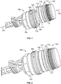
- Figure 1 is a diagrammatic representation of a perspective lateral view of a first electrical connector 100 disconnected from a second electrical connector 102, according to an embodiment of the present disclosure.
- the first and second electrical connectors 100 and 102 are configured to convey electrical signals therebetween when connected together.
- the first electrical connector 100 may be a shipside connector that is operatively coupled to a main electrical board or power panel within a galley of an aircraft through a cable, for example.
- the second electrical connector 102 may be a test connector that is operatively coupled to a testing device through a cable, for example.
- the first electrical connector 100 includes a backplane 104 that connects to a torque ring 106 and a connection interface 108.
- the connection interface 108 is configured to mate with a reciprocal connection interface 110 of the second electrical connector 102.
- the connection interface 108 may have a diameter 112 that is at least 5.1cm (2 inches). Alternatively, the diameter 112 may be less than 5.1cm (2 inches).
- the connection interface 108 may be circular.
- the connection interface 108 and the connection interface 110 may be various other shapes and sizes, such as square, triangular, elliptical, ovoid, and/or the like.
- the second electrical connector 102 includes the connection interface 110 that connects to a flat planar flange 114 that extends radially outward from the connection interface 110.
- the connection interface 110 may include an outer circumferential rim 116 that defines a contact chamber (hidden from view) that is configured to mate with a contact chamber 118 of the first electrical connector 100.
- the contact chamber of the second electrical connector 102 may include a plurality of electrical contacts (not shown) that are configured to electrically connect to a corresponding number of reciprocal electrical contacts (not shown) within the contact chamber 118 of the first electrical connector 100 when the first electrical connector 100 is connected to the second electrical connector 102.
- the first electrical connector 100 may include a receptacle 120.
- the receptacle 120 is configured to mate with a rim 116 of the second electrical connector 102.
- the first electrical connector 100 may include the plug, and the second electrical connector 102 may include the receptacle.
- connection interfaces 108 and 110 are axially aligned with one another so that the plug 116 is axially aligned with the receptacle 120.
- the second electrical connector 102 is linearly urged toward the first electrical connector 100 in the direction of linear arrow 122 (or the first electrical connector 100 is linearly urged toward the first electrical connector in the direction of linear arrow 124).
- the receptacle 120 of the first electrical connector 100 linearly receives the rim 116 of the second electrical connector 102.
- the first electrical connector 100 mates with the second electrical connector through a single, simple linear, non-rotational motion, such as a plugging motion.
- the first and second electrical connectors 100 and 102 are not rotated into a mating connection.
- the connection interfaces 108 and 110 of the respect first and second electrical connectors 100 and 102 are devoid of threads or other such rotatable connection interfaces.
- FIG 2 is a diagrammatic representation of a perspective lateral view of the first electrical connector 100 initially mated with the second electrical connector 102, according to an embodiment of the present disclosure.
- the first and second electrical connectors 100 and 102 are linearly mated with each other (in contrast to being to be rotationally mated).
- a retaining harness assembly (not shown in Figure 2 ) is used to ensure that the first and second electrical connectors 100 and 102 remain securely mated to one another. That is, the retaining harness assembly is configured to maintain a secure mating relationship between the first and second electrical connectors 100 and 102.
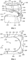
- FIG 3 is a diagrammatic representation of a perspective top view of a retaining harness assembly 200, according to an embodiment of the present disclosure.
- Figure 4 is a diagrammatic representation of a top view of the retaining harness assembly 200.
- Figure 5 is a diagrammatic representation of a perspective front view of the retaining harness assembly 200.
- the retaining harness assembly 200 may be integrally molded and formed as a single piece of plastic.
- the retaining harness assembly 200 may be formed of separate and distinct portions that are secured together, such as through fasteners, adhesives, and/or the like.
- the retaining harness assembly 200 may be formed of various other materials, such as one or more metals.
- the retaining harness assembly 200 includes a rear wall 202 connected to opposed lateral walls 204.
- the rear wall 202 connects to the lateral walls 204 through curved transition walls 206.
- the rear wall 202 may be perpendicular to the lateral walls 204.
- Each lateral wall 204 includes a free end 208. That is, the retaining harness assembly 200 may not include a front wall that extends between the lateral walls 204. Instead, an opening 210 is formed between the free ends 208 of the lateral walls 204 and leads to a connecting chamber 212 that is defined between interior surfaces of the lateral wall 204 and the rear wall 202.
- a lower ledge 214 extends from lower portions of the lateral walls 204 and the rear wall 202 and extends inwardly into the connecting chamber 212.
- the lower ledge 214 may include linear edges 216 that extend inwardly from the lateral wall 204.
- the linear edges 216 connect to a semi-circular edge 218 that inwardly extends from the rear wall 202 into the connecting chamber 212.
- the shape and size of the lower ledge 214, including the linear edges 216 and the semi-circular edge 218, may be sized and shaped to conform to a size and shape of an outer surface of a portion of the second electrical connector 102 (shown in Figures 1 and 2 ).
- Inwardly-angled lead-in walls 220 may extend upwardly from the lower ledge 214 proximate to the free ends 208 of the lateral walls 204.
- the lead-in walls 220 connect to a flange-receiving slot 222 positioned between the lower ledge 214 and an upper ledge 224, which may follow the contour of the lower ledge 214 within the connecting chamber 212 proximate to the rear wall 202.
- the retaining harness assembly 200 may not include the lead-in walls 220.
- a retaining collar 230 may extend from upper edges of the lateral walls 204 and the rear wall 202.
- the retaining collar 230 may be inwardly bent and perpendicular with respect to the lateral walls 204 and the rear wall 202.
- the retaining collar 230 may be parallel to the lower ledge 214 and the upper ledge 224.
- Inner edges of the retaining collar 230 may be sized and shaped to conform to outer surfaces of a portion of the first electrical connector 100 (shown in Figures 1 and 2 ).
- the retaining collar 230 may include recessed areas 226 proximate to the curved transition walls 206.
- the recessed areas 226 may be divots formed in the retaining collar 230.
- the recessed areas 226 may be areas in which no portion of the retaining collar 230 extends over the connecting chamber 212.
- the retaining collar 230 may not extend over the curved transition walls 206.
- the recessed areas 220 may include arcuate surfaces 228 that provide a thinned area of the retaining collar 230 (or optionally, an area that is devoid of the retaining collar 230).
- the recessed areas 226 provide the retaining collar 230 with resilient, flexible areas that are configured to allow the lateral walls 204 to smoothly deflect, such as by flexing open with respect to the rear wall 202 when an outwardly-directed flexing force is exerted into the lateral walls 204 (for example, when an individual grasps the free ends 208 and spreads the lateral walls 204 open).
- the retaining collar 230 may not include the recessed areas 220.
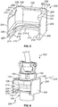
- Figure 6 is a diagrammatic representation of a perspective front view of the retaining harness assembly 200 securely connecting the first electrical connector 100 to the second electrical connector 102, according to an embodiment of the present disclosure.
- Figure 6 shows an electrical system, such as a system for securely, safely, efficiently, and easily maintaining a secure connection between the first and second electrical connectors 100 and 102.
- the retaining harness assembly 200 is used to ensure a secure mated connection between the first and second electrical connectors 100 and 102.
- the retaining harness assembly 200 allows the first and second electrical connectors 100 and 102 to securely engage each other, connect, and securely mate together without the connectors 100 and 102 or the retaining harness assembly 200 being rotated (for example, torqued) relative to another component.
- the first and second electrical connectors 100 and 102 are first mated together in a linear, non-rotational direction.
- the retaining harness assembly 200 is secured around portions of the first and second electrical connectors 100 and 102.
- the retaining harness assembly 200 is configured to bias portions of the first and second electrical connectors 100 and 102 toward one another in order to maintain a secure mating relationship therebetween.
- the retaining harness assembly 200 may be configured to clamp the first and second electrical connectors 100 and 102 together.
- the lead-in walls 220 are aligned with the flange 114 of the second electrical connector 102 and the retaining collar 230 is aligned over an upper edge 170 of the torque ring 106 of the first electrical connector 100.
- the retaining harness assembly 200 is then urged toward the first and second electrical connectors 100 and 102.
- distal portions 231 of the retaining collar 230 may be expanded so that a distance between opposed distal portions 231 is less than a diameter of the backplane 104 around which the retaining collar 230 secures. As such, as the distal portions 231 slide over the outer surface of the backplane 104, the lateral walls 204 may outwardly deflect.
- recessed interior edges 233 of the retaining collar 230 engage around the outer surface of the backplane 104, and the lateral walls 204 deflect back to an at-rest position, such that opposed distal portions 231 provide a barrier that traps the backplane 104 within the retaining collar 230.
- the retaining collar 230 prevents the first electrical connector 100 (and therefore the second electrical connector 102 that connects to the first electrical connector 100) from axially, radially, or longitudinally shifting.
- the flange 114 is nestled within the flange-receiving slot 222 and supported by the lower ledge 214, while the retaining collar 230 securely wraps around a portion of the backplane 104 and extends over the upper edge 170 of the torque ring 106.
- the lower ledge 214 exerts a retaining force into the flange 114 in the direction of arrow 250, while the retaining collar 230 exerts a retaining force into the upper edge 170 of the torque ring 106 in the direction of arrow 252, which is opposite from the direction of arrow 250. Therefore, the retaining harness assembly 200 provides opposed retaining forces that ensure that the first and second electrical connectors 100 and 102 remain securely mated together.
- the retaining harness assembly 200 effectively clamps the first and second electrical connectors 100 and 102 together.
- the retaining harness assembly 200 provides a bracing support that prevents the first electrical connector 100 from dislodging from the second electrical connector 102.
- the lateral walls 204 of the retaining harness assembly 200 may be grasped and spread open.
- the distal portions 231 of the retaining collar 230 disengage from the backplane 104, and the first and second electrical connectors 100 and 102 may be removed from the connecting chamber 212 (such as by moving the retaining harness assembly 200 in a linear direction that is substantially perpendicular to a longitudinal axis that passes through the centers of the first and second electrical connectors 100 and 102).
- the first electrical connector 100 may be linearly disconnected from the second electrical connector 102, or vice versa, such as through a simple unplugging movement.
- Figure 7 is a diagrammatic representation of a perspective front view of an example retaining harness assembly 300 securely connecting the first electrical connector 100 to the second electrical connector 102, according to an example of the present disclosure.
- Figure 7 shows an example electrical system that is configured to maintain a secure mating relationship between the first and second electrical connectors 100 and 102.
- the retaining harness assembly 300 is similar to the retaining harness assembly 200 (shown in Figures 3-6 ).
- the retaining harness assembly 300 may include a securing strap 302 that abuts into a lower surface of the flange 114.
- the securing strap 302 may connect to upwardly extending retaining arms 304, each of which may include a protuberance 306 that abuts into the backplane 104 and is supported over the edge 170 of the torque ring 106.
- the protuberances 306 may extend from distal ends of the retaining arms 304, and may be perpendicular to extension beams 307 of the retaining arms 304. More or less retaining arms 304 than shown may be used.
- the protuberance 306 may be or otherwise include a tab, clasp, latch, barb, or the like.
- the securing strap 302 exerts a retaining force into the flange 114 in a first direction 310, while the protuberances 306 exert retaining forces into the edge 170 of the torque ring 106 in a second direction 312 that is opposite the first direction 310.
- the retaining harness assembly 300 provides retaining forces that ensure that the first electrical connector 100 remains securely mated with the second electrical connector 102.
- the retaining harness assembly 300 is configured to maintain the first and second electrical connectors 100 and 102 in a secure mated relationship. Similar to the retaining harness assembly 200 (shown in Figures 3-6 ), the retaining harness assembly 300 is configured to clamp the first and second electrical connectors 100 and 102 together.
- the protuberances 306 may be engaged (for example, grasped) by an individual and spread outwardly from one another, thereby deflecting the retaining arms 304 apart. As the protuberances 306 spread outwardly, the protuberances 306 disengage from the torque ring 106. As such, the retaining harness assembly 300 may disconnect from a secure clamping positon and slide down toward the flange 114, onto which the protuberances 306 may catch.
- the retaining harness assembly 300 may include an opening between wall portions so that the retaining harness assembly 300 may be completely removed from the second electrical connector 102. After the retaining harness assembly 300 disengages the first electrical connector 100, the first electrical connector 100 may be disconnected from the second electrical connector 102, or vice versa, in a linear direction, such as through an unplugging movement.
- Figure 8 illustrates a flow chart of a method of selectively connecting and disconnecting first and second electrical connectors, according to an example of the present disclosure.
- the method begins at 400, in which first and second electrical connectors are linearly urged together.
- the first and second electrical connectors may be plugged together in a linear, non-rotational direction.
- the first electrical connector is a shipside connector that is coupled to a main electrical board and/or power panel of the galley, while the second electrical connector is a test connector coupled to an electrical testing device.
- a retaining harness assembly is aligned with a portion of the first electrical connector and a portion of the second electrical connector.
- the retaining harness assembly is urged onto the first and second electrical connectors to provide opposed retaining forces that maintain a secure mating connection between the first and second electrical connectors.
- deflectable portions of the retaining harness assembly may deflect outwardly and snap back to an at-rest position to securely trap a portion of at least one of the first and second electrical connectors therebetween.
- the method proceeds to 410, in which an individual engages (for example, grasps) the deflectable portions and removes the retaining harness assembly from the first and second electrical connectors. Then, at 412, with the retaining harness assembly removed from a securing connection, the first and second electrical connectors may be linearly disconnected, such as by being unplugged.
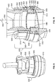
- FIG. 9 is a diagrammatic representation of a perspective front view of a further example retaining harness assembly 500 secured to a first electrical connector 502, according to a further example of the present disclosure.
- the first electrical connector 502 may be similar to the first electrical connector described above.
- the retaining harness assembly 500 may include a retainer housing 504 secured around a portion of a backshell 506 of the first electrical connector 502, and a spring override ring 508 secured around a portion of the retainer housing 504 and operatively coupled to a torque ring 510.
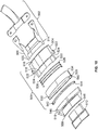
- Figure 10 is a diagrammatic representation of a perspective exploded view of the first electrical connector 502 and the retaining harness assembly 500, according to an example of the present disclosure.
- Figure 10 shows an electrical system configured to maintain a secure mating relationship between the first electrical connector 502 and a second electrical connector, such as the second electrical connector 102 shown in Figure 1 .
- the backshell 506 may include a cylindrical main body 514 that fits within a reciprocal channel 516 formed in the retainer housing 504.
- the retainer housing 504 may include an interior ledge 518 that supports a lower base edge 520 of the backshell 506.
- the retainer housing 504 may also include an outer circumferential shroud 522.
- the shroud 522 may include an open ended channel 524 that is configured to receive a portion of a biasing spring 526.
- the spring 526 includes an end 528 that abuts into an interior surface of the shroud 522.
- the spring 526 wraps around an override end 530 of the retainer housing 504 and is urged into an internal annular ledge 532 of the spring override ring 508.
- An outer circumferential wall 534 of the spring override ring 508 may surround an outer circumference of at least a portion of the spring 526.
- the spring override ring 508 may also include a lower ratchet interface 540 that is configured to mate with a reciprocal upper ratchet interface 542 of a ratchet ring 544 that is positioned on a ledge 546 of the torque ring 510.
- the ratchet ring 544 may be a separate and distinct piece that lies within the torque ring 510.
- the ratchet ring 544 may include securing members, such as splines, tabs, or the like, that are configured to be securely retained by reciprocal structures of the torque ring 510.
- the ratchet ring 544 may be an integral part of the torque ring 510.
- a connection interface 512 includes an insert 548 that is configured to be received and retained by a receptacle 550 of the torque ring 510.
- the connection interface 512 may include the receptacle while the torque ring 510 includes the plug.
- FIG 11 is a diagrammatic representation of a perspective axial cross-sectional view of the first electrical connector 502 secured to the retaining harness assembly 500, according to an example of the present disclosure.
- the backshell 506 may include a threaded outer interface 552 that threadably secures to a threaded inner interface 554 of the main body 514 of the retainer housing 504.
- the plug 548 may include a threaded outer interface 560 that threadably secures to a threaded inner interface 562 of the override end 530 of the retainer housing 504.
- the connection interface 512 may threadably secure to the first electrical connector 502 through rotational engagement.
- the connection interface 512 may secured to the retainer housing 504 through an interference fit, a press fit, bonding, fasteners, and/or the like.
- connection interface 512 As shown, a channel 549 is defined between an outer surface of connection interface 512 and an interior surface of the torque ring 512.
- a portion of a second electrical connector, such as the rim 116 of the connection interface 110 of the second electrical connector 102 (shown in Figure 1 ) is configured to be positioned and secured within the connection interface 512.
- the spring 526 biases the spring override ring 508 into the ratchet ring 544.
- the lower ratchet interface 540 of the spring override ring 508 securely engages the upper ratchet interface 542 of the ratchet ring 544, which is compressed into and retained by the torque ring 510.
- the torque ring 510 prevents the first electrical connector 502 from being rotated relative to the second electrical connector (such as the second electrical connector 102) in the connected position.
- the spring override ring 508 may be rotated about a central longitudinal axis 580 in the direction of arc 582.
- the spring override ring 508 may be rotated a quarter turn in the direction of arc 582.
- one or more protuberances such as posts, nubs, studs, or the like
- the spring override ring 508 engages the spring 526, which causes the spring 526 to retract upwardly in the direction of arrow 590 toward the shroud 522.
- the force of the spring 526 exerted into the ledge 532 is released, and the lower ratchet interface 540 disengages from the upper ratchet interface 542. Accordingly, the torque ring 510 may then be rotated, which may threadably disengage the first electrical connector 502 from the second electrical connector (such as the second electrical connector 102 shown in Figure 1 ).
- the override ring 508 may be easily rotated relative to the retainer housing 504 and the torque ring 510.
- the spring 526 is drawn towards the first electrical connector 502 (for example, the spring 526 compresses into a barrier surface of the shroud 522), which releases the securing bias between the spring override ring 508 and the torque ring 510.
- the spring 526 remains compressed toward the first electrical connector 502 until an individual rotates the override ring in an opposite direction from arc 582.
- the torque ring 510 may no longer secure to the second electrical connector at an elevated force. As such, the torque ring 510 may then be easily rotated in order to threadably disengage the first electrical connector 502 from the second electrical connector.
- Figure 12 is a diagrammatic representation of a front view of the spring 526 secured around a portion of a retainer housing 504, according to an example of the present disclosure.
- the override end 530 may include one or more angled tracks 600 formed therethrough.
- the angled track(s) 600 is configured to receive one or more inwardly directed protuberances of the spring override ring 508 (shown in Figure 11 , for example).
- the protuberance(s) upwardly rotates in the track(s) 600, thereby compressing the spring 526 toward and/or into the shroud 522.
- An end 602 of a track 600 may provide a downwardly canted portion that is configured to secure a protuberance in a securely locked position, which ensures that the spring 526 remains compressed (and the torque ring 510, which is shown in Figure 11 , remains in a free rotational state).
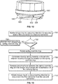
- Figure 13 illustrates a flow chart of a method of selectively connecting and disconnecting first and second electrical connectors, according to an example of the present disclosure.
- the method begins at 700, in which a torque ring is rotated in a securing direction to securely mate a first electrical connecter that is threadably connected to a second electrical connector.
- the spring override ring is rotated in relation to the torque ring and a retainer housing.
- the spring override ring may be rotated a quarter turn in a direction that is opposite from the securing direction in which the torque ring was rotated.
- a biasing spring secured between the spring override ring and the retainer housing is compressed toward a shroud of the retainer housing.
- a securing force between the spring override ring and the torque ring is released due to the compression of the biasing spring.
- the torque ring may be rotated in a disconnecting direction at 712 in order to threadably disconnect the first electrical connector from the second electrical connector.
- inventions and examples of the present disclosure provide safe and simple systems and methods for securing a first electrical connector to a second electrical connector.
- the first electrical connector may be a shipside connector that is coupled to an electrical board or power panel of a galley within an aircraft, for example.
- the second electrical connector may be a test connector that is coupled to a testing device used to electrically test various components within the galley.
- embodiments and examples of the present disclosure allow a shipside connector within a galley of an aircraft to be connected and disconnected to a test connector with less force than prior known systems and methods. It has been found that embodiments and examples of the present disclosure reduce a likelihood of injury caused by connecting and/or disconnecting a shipside connector to a test connector. In contrast to prior known connectors that required high levels of connection and disconnection force exerted with strap wrenches, for example, embodiments and examples of the present disclosure eliminate, minimize, or otherwise reduce a likelihood of injury to an individual.
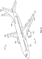
- Figure 14 illustrates a perspective top view of an aircraft 810 (or aircraft assembly), according to an example of the present disclosure.
- the aircraft 810 may include a propulsion system 812 that may include two turbofan engines 814, for example.
- the propulsion system 812 may include more engines 814 than shown.
- the engines 814 are carried by wings 816 of the aircraft 810.
- the engines 814 may be carried by a fuselage 818 and/or an empennage 820.
- the empennage 820 may also support horizontal stabilizers 822 and a vertical stabilizer 824.
- the fuselage 818 of the aircraft 810 defines an internal cabin, which may include a cockpit, one or more work sections (for example, galleys, personnel carry-on baggage areas, and the like), one or more passenger sections (for example, first class, business class, and coach sections), and an aft section in which an aft rest area assembly may be positioned.
- Each of the sections may be separated by a cabin transition area, which may include a curtain assembly having a moveable curtain that may be selectively opened and closed within an aisle.
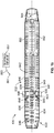
- Figure 15 illustrates a top plan view of a layout of an internal cabin 830 of an aircraft, according to an example of the present disclosure.
- the internal cabin 830 may be within a fuselage 832 of the aircraft.
- one or more fuselage walls may define the internal cabin 830.
- the internal cabin 830 includes multiple sections, including a front section 833, a first class section 834, a business class section 836, a front galley station 838, an expanded economy or coach section 840, a standard economy of coach section 842, and an aft section 844, which may include multiple lavatories and galley stations. It is to be understood that the internal cabin 830 may include more or less sections than shown.
- the internal cabin 830 may not include a first class section, and may include more or less galley stations than shown.
- Each of the sections may be separated by a cabin transition area 846, which may include curtain assemblies between structural features (such as monuments, overhead bins, or the like) within aisles 848.
- the front galley station 838 may include a power panel 839.
- a first or shipside connector 841 may couple to the power panel 839 through a cable 843. Additional power panels, shipside connectors, and cables maybe located throughout the internal cabin.
- a testing device 851 may be used to test components within or coupled to the power panel 839 of the front galley station 838.
- the testing device 851 may connect to the power panel 839 by way of a second or test connector 861 (that couples to the testing device 851 through a cable 863) removably connecting to the shipside connector 841, such as described above with respect to Figures 1-13 .
- the testing device 851 may be a mobile structure that is configured to be moved into and out of the internal cabin 830.
- the internal cabin 830 includes two aisles 850 and 852 that lead to the aft section 844.
- the internal cabin 830 may have less or more aisles than shown.
- the internal cabin 830 may include a single aisle that extends through the center of the internal cabin 830 that leads to the aft section 844.
- a structure, limitation, or element that is "configured to” perform a task or operation is particularly structurally formed, constructed, or adapted in a manner corresponding to the task or operation.
- an object described above that is merely capable of being modified to perform the task or operation is not “configured to” perform the task or operation as used in the above description.
Landscapes
- Physics & Mathematics (AREA)
- General Physics & Mathematics (AREA)
- Details Of Connecting Devices For Male And Female Coupling (AREA)
Claims (7)
- Elektrisches System, das aufweist:einen ersten elektrischen Steckverbinder (100), der dazu geeignet ist, mit einem Elektroschalterbrett verbunden zu werden;einen zweiten elektrischen Steckverbinder (102), der dazu geeignet ist, mit einem Testgerät verbunden zu werden, das dazu konfiguriert ist, eine Komponente zu testen, die mit dem Elektroschalterbrett verbunden ist; undeine Haltegurtanordnung (200), die abnehmbar mit den ersten und zweiten elektrischen Steckverbindern (100, 102) verbunden wird, um eine sichere passende Beziehung zwischen den ersten und zweiten elektrischen Steckverbindern (100, 102) aufrecht zu erhalten, wobei die Haltegurtanordnung (200) aufweist: eine hintere Wand (202), die mit gegenüberliegenden Seitenwänden (204) verbunden ist, wobei eine Verbindungskammer (212) zwischen der hinteren Wand (202) und den Seitenwänden (204) definiert ist; eine untere Leiste (214), die von einer oberen Leiste (224) durch einen flanschaufnehmenden Schlitz (222) getrennt ist, wobei ein Flansch (114) des zweiten elektrischen Steckverbinders (102) in dem flanschaufnehmenden Schlitz (222) aufgenommen und gehalten wird, wobei die untere Leiste (214) eine erste Haltekraft auf den Flansch (114) ausübt;wobei die Haltegurtanordnung (200) des Weiteren aufweist: einen Haltekragen (230), der um einen Abschnitt einer Rückplatte (104) des ersten elektrischen Steckverbinders (100) herum absichert und in einem Drehmomentring (106) des ersten elektrischen Steckverbinders (100) anschlägt, wobei der Drehmomentring (106) dazu ausgelegt ist, eine sichere Verbindung zwischen den ersten und zweiten elektrischen Steckverbindern bereitzustellen, wenn er angezogen oder anderweitig gedreht wird, wobei der Haltekragen (230) eine zweite Haltekraft auf den Drehmomentring (106) ausübt, wobei der Haltekragen (230) eine oder mehrere erste zurückgesetzte Bereiche (233) aufweist, die dazu konfiguriert sind, mit einem Abschnitt einer äußeren Oberfläche der Rückplatte (104) übereinzustimmen, und die gegenüberliegenden seitlichen Wände (204) dazu konfiguriert sind, in eine offene Position abgelenkt zu werden, um die Haltegurtanordnung (200) von den ersten und zweiten elektrischen Steckverbindern (100, 102) zu entfernen.
- Elektrisches System nach Anspruch 1, wobei die ersten und zweiten elektrischen Steckverbinder (100, 102) dazu konfiguriert sind, in einer linearen Richtung ohne Drehung zusammen zu passen.
- Elektrisches System nach Anspruch 1, wobei einer oder beide der ersten und zweiten elektrischen Steckverbinder (100, 102) keine mit Gewinde versehene Verbindungsschnittstelle hat/haben.
- Elektrisches System nach einem der Ansprüche 1 bis 3, wobei die Haltegurtanordnung (200) dazu ausgelegt ist, den ersten elektrischen Steckverbinder (100) in Richtung des zweiten elektrischen Steckverbinders (102) vorzuspannen.
- Elektrisches System nach Anspruch 1, wobei die Haltegurtanordnung (200) des Weiteren eine oder mehrere nach innen gewinkelte Einführungswände (220) hat, die sich von der unteren Kante (214) nahe freien Enden (208) der seitlichen Wände (204) nach oben erstrecken und sich mit dem flanschaufnehmenden Schlitz (222) verbinden.
- Elektrisches System nach einem der vorhergehenden Ansprüche, wobei die hintere Wand (202) mit den seitlichen Wänden (204) durch gebogene Übergangswände (206) verbunden ist und der Haltekragen (230) des Weiteren einen oder mehrere zweite zurückgesetzte Bereiche (226) nahe den gebogenen Übergangswänden (206) aufweist.
- Elektrisches System nach Anspruch 6, wobei die zweiten zurückgesetzten Bereiche (226) bogenförmige Oberflächen (228) aufweisen, die einen dünnen oder fehlenden Bereich des Haltekragens (230) bereitstellen, so dass die zweiten zurückgesetzten Bereiche (226) den Haltekragen (230) mit nachgiebigen, biegsamen Bereichen versehen, die ermöglichen, dass die gegenüberliegenden seitlichen Wände (204) in eine offene Position abgelenkt werden, um die Haltegurtanordnung (200) von den ersten und zweiten elektrischen Steckverbindern (100, 102) zu entfernen.
Applications Claiming Priority (1)
| Application Number | Priority Date | Filing Date | Title |
|---|---|---|---|
| US14/827,449 US9689895B2 (en) | 2015-08-17 | 2015-08-17 | Test connector retaining harness assembly |
Publications (3)
| Publication Number | Publication Date |
|---|---|
| EP3133703A2 EP3133703A2 (de) | 2017-02-22 |
| EP3133703A3 EP3133703A3 (de) | 2017-05-10 |
| EP3133703B1 true EP3133703B1 (de) | 2019-10-09 |
Family
ID=56997302
Family Applications (1)
| Application Number | Title | Priority Date | Filing Date |
|---|---|---|---|
| EP16184206.7A Active EP3133703B1 (de) | 2015-08-17 | 2016-08-15 | Teststeckerhaltende kabelbaumanordnung |
Country Status (2)
| Country | Link |
|---|---|
| US (1) | US9689895B2 (de) |
| EP (1) | EP3133703B1 (de) |
Families Citing this family (2)
| Publication number | Priority date | Publication date | Assignee | Title |
|---|---|---|---|---|
| DE102015010042A1 (de) * | 2015-08-01 | 2017-02-02 | GM Global Technology Operations LLC (n. d. Ges. d. Staates Delaware) | Prüfanordnung zur Prüfung mindestens einer Verbindungsschnittstelle und Verfahren zur Prüfung mindestens einer Verbindungsschnittstelle mit einer Prüfanordnung |
| CN121440285A (zh) * | 2025-03-05 | 2026-01-30 | 扬中市优乐电气有限公司 | 一种弹性电缆用电力金具连接器 |
Citations (1)
| Publication number | Priority date | Publication date | Assignee | Title |
|---|---|---|---|---|
| JP2005203303A (ja) * | 2004-01-19 | 2005-07-28 | Daifuku Co Ltd | ロック装置付きケーブルコネクタ |
Family Cites Families (4)
| Publication number | Priority date | Publication date | Assignee | Title |
|---|---|---|---|---|
| US5013258A (en) | 1990-01-29 | 1991-05-07 | G.K.I. | Latching assembly for a light bulb and electrical socket |
| US5655924A (en) * | 1996-06-10 | 1997-08-12 | The Dzyne Group, Ltd. | Electrical plug retainer system |
| JP2006031967A (ja) | 2004-07-12 | 2006-02-02 | Yazaki Corp | コネクタ |
| FR2931305B1 (fr) | 2008-05-14 | 2010-06-04 | Radiall Sa | Connecteur multicontacts avec piece de verrouillage integree dans l'epaisseur d'un boitier |
-
2015
- 2015-08-17 US US14/827,449 patent/US9689895B2/en active Active
-
2016
- 2016-08-15 EP EP16184206.7A patent/EP3133703B1/de active Active
Patent Citations (1)
| Publication number | Priority date | Publication date | Assignee | Title |
|---|---|---|---|---|
| JP2005203303A (ja) * | 2004-01-19 | 2005-07-28 | Daifuku Co Ltd | ロック装置付きケーブルコネクタ |
Also Published As
| Publication number | Publication date |
|---|---|
| US20170052212A1 (en) | 2017-02-23 |
| EP3133703A2 (de) | 2017-02-22 |
| EP3133703A3 (de) | 2017-05-10 |
| US9689895B2 (en) | 2017-06-27 |
Similar Documents
| Publication | Publication Date | Title |
|---|---|---|
| US7758370B1 (en) | Quick release electrical connector | |
| CN102904107B (zh) | 带缆线夹箝部的电连接器 | |
| US5938465A (en) | Machined dual spring ring connector for coaxial cable | |
| TWI487211B (zh) | 具有鎖定機構的連接器及相關的系統及方法 | |
| US8961224B2 (en) | Coupling system for electrical connector assembly | |
| US9257780B2 (en) | Coaxial cable connector with weather seal | |
| US9688251B2 (en) | Wiper connector and bolt-stabilizing sleeve adaptor | |
| US9065207B2 (en) | Locking electrical receptacle | |
| US20120329311A1 (en) | Cable connector with bushing element | |
| EP3440747B1 (de) | Verbindungssystem mit adaptiertem bajonettverschlussvorrichtung zum schnellen lösen | |
| EP2822105A1 (de) | Kopplungssystem für elektrische Verbinderanordnung | |
| US20160036138A1 (en) | Coaxial cable connectors with conductor retaining members | |
| US9689895B2 (en) | Test connector retaining harness assembly | |
| EP2684258B1 (de) | Elektrosteckerzubehör und montageverfahren dafür | |
| EP3169583A1 (de) | Modulare montagestruktur mit eingebettetem elektrischem rohrleiter | |
| US7097490B2 (en) | Electrical connector | |
| US20060079109A1 (en) | Quick-disconnect threaded connector | |
| WO2017187314A1 (en) | Electrical connector having latch release collar | |
| US10218122B1 (en) | Circular connector and method of retaining components | |
| US9517564B1 (en) | Fiber clamp with attachment accessory nub and receptacle | |
| US10790615B2 (en) | Cable quick connector adapter | |
| US9194409B2 (en) | Disconnect device | |
| KR20200001429U (ko) | 동축케이블용 커넥터 체결구조 | |
| US9197008B1 (en) | Electrical assembly having a threaded coupling nut and retaining ring | |
| CN210350270U (zh) | 带保险锁扣的快速插拔圆形接口连接器 |
Legal Events
| Date | Code | Title | Description |
|---|---|---|---|
| PUAI | Public reference made under article 153(3) epc to a published international application that has entered the european phase |
Free format text: ORIGINAL CODE: 0009012 |
|
| STAA | Information on the status of an ep patent application or granted ep patent |
Free format text: STATUS: REQUEST FOR EXAMINATION WAS MADE |
|
| 17P | Request for examination filed |
Effective date: 20160815 |
|
| AK | Designated contracting states |
Kind code of ref document: A2 Designated state(s): AL AT BE BG CH CY CZ DE DK EE ES FI FR GB GR HR HU IE IS IT LI LT LU LV MC MK MT NL NO PL PT RO RS SE SI SK SM TR |
|
| AX | Request for extension of the european patent |
Extension state: BA ME |
|
| PUAL | Search report despatched |
Free format text: ORIGINAL CODE: 0009013 |
|
| AK | Designated contracting states |
Kind code of ref document: A3 Designated state(s): AL AT BE BG CH CY CZ DE DK EE ES FI FR GB GR HR HU IE IS IT LI LT LU LV MC MK MT NL NO PL PT RO RS SE SI SK SM TR |
|
| AX | Request for extension of the european patent |
Extension state: BA ME |
|
| RIC1 | Information provided on ipc code assigned before grant |
Ipc: H01R 13/639 20060101AFI20170401BHEP |
|
| STAA | Information on the status of an ep patent application or granted ep patent |
Free format text: STATUS: EXAMINATION IS IN PROGRESS |
|
| 17Q | First examination report despatched |
Effective date: 20180702 |
|
| GRAP | Despatch of communication of intention to grant a patent |
Free format text: ORIGINAL CODE: EPIDOSNIGR1 |
|
| STAA | Information on the status of an ep patent application or granted ep patent |
Free format text: STATUS: GRANT OF PATENT IS INTENDED |
|
| INTG | Intention to grant announced |
Effective date: 20190401 |
|
| GRAJ | Information related to disapproval of communication of intention to grant by the applicant or resumption of examination proceedings by the epo deleted |
Free format text: ORIGINAL CODE: EPIDOSDIGR1 |
|
| STAA | Information on the status of an ep patent application or granted ep patent |
Free format text: STATUS: EXAMINATION IS IN PROGRESS |
|
| GRAR | Information related to intention to grant a patent recorded |
Free format text: ORIGINAL CODE: EPIDOSNIGR71 |
|
| GRAS | Grant fee paid |
Free format text: ORIGINAL CODE: EPIDOSNIGR3 |
|
| STAA | Information on the status of an ep patent application or granted ep patent |
Free format text: STATUS: GRANT OF PATENT IS INTENDED |
|
| INTC | Intention to grant announced (deleted) | ||
| GRAA | (expected) grant |
Free format text: ORIGINAL CODE: 0009210 |
|
| STAA | Information on the status of an ep patent application or granted ep patent |
Free format text: STATUS: THE PATENT HAS BEEN GRANTED |
|
| INTG | Intention to grant announced |
Effective date: 20190806 |
|
| AK | Designated contracting states |
Kind code of ref document: B1 Designated state(s): AL AT BE BG CH CY CZ DE DK EE ES FI FR GB GR HR HU IE IS IT LI LT LU LV MC MK MT NL NO PL PT RO RS SE SI SK SM TR |
|
| REG | Reference to a national code |
Ref country code: GB Ref legal event code: FG4D |
|
| REG | Reference to a national code |
Ref country code: CH Ref legal event code: EP |
|
| REG | Reference to a national code |
Ref country code: IE Ref legal event code: FG4D |
|
| REG | Reference to a national code |
Ref country code: DE Ref legal event code: R096 Ref document number: 602016021999 Country of ref document: DE |
|
| REG | Reference to a national code |
Ref country code: AT Ref legal event code: REF Ref document number: 1189917 Country of ref document: AT Kind code of ref document: T Effective date: 20191115 |
|
| REG | Reference to a national code |
Ref country code: NL Ref legal event code: MP Effective date: 20191009 |
|
| REG | Reference to a national code |
Ref country code: LT Ref legal event code: MG4D |
|
| REG | Reference to a national code |
Ref country code: AT Ref legal event code: MK05 Ref document number: 1189917 Country of ref document: AT Kind code of ref document: T Effective date: 20191009 |
|
| PG25 | Lapsed in a contracting state [announced via postgrant information from national office to epo] |
Ref country code: GR Free format text: LAPSE BECAUSE OF FAILURE TO SUBMIT A TRANSLATION OF THE DESCRIPTION OR TO PAY THE FEE WITHIN THE PRESCRIBED TIME-LIMIT Effective date: 20200110 Ref country code: BG Free format text: LAPSE BECAUSE OF FAILURE TO SUBMIT A TRANSLATION OF THE DESCRIPTION OR TO PAY THE FEE WITHIN THE PRESCRIBED TIME-LIMIT Effective date: 20200109 Ref country code: FI Free format text: LAPSE BECAUSE OF FAILURE TO SUBMIT A TRANSLATION OF THE DESCRIPTION OR TO PAY THE FEE WITHIN THE PRESCRIBED TIME-LIMIT Effective date: 20191009 Ref country code: AT Free format text: LAPSE BECAUSE OF FAILURE TO SUBMIT A TRANSLATION OF THE DESCRIPTION OR TO PAY THE FEE WITHIN THE PRESCRIBED TIME-LIMIT Effective date: 20191009 Ref country code: SE Free format text: LAPSE BECAUSE OF FAILURE TO SUBMIT A TRANSLATION OF THE DESCRIPTION OR TO PAY THE FEE WITHIN THE PRESCRIBED TIME-LIMIT Effective date: 20191009 Ref country code: LV Free format text: LAPSE BECAUSE OF FAILURE TO SUBMIT A TRANSLATION OF THE DESCRIPTION OR TO PAY THE FEE WITHIN THE PRESCRIBED TIME-LIMIT Effective date: 20191009 Ref country code: PL Free format text: LAPSE BECAUSE OF FAILURE TO SUBMIT A TRANSLATION OF THE DESCRIPTION OR TO PAY THE FEE WITHIN THE PRESCRIBED TIME-LIMIT Effective date: 20191009 Ref country code: NO Free format text: LAPSE BECAUSE OF FAILURE TO SUBMIT A TRANSLATION OF THE DESCRIPTION OR TO PAY THE FEE WITHIN THE PRESCRIBED TIME-LIMIT Effective date: 20200109 Ref country code: ES Free format text: LAPSE BECAUSE OF FAILURE TO SUBMIT A TRANSLATION OF THE DESCRIPTION OR TO PAY THE FEE WITHIN THE PRESCRIBED TIME-LIMIT Effective date: 20191009 Ref country code: LT Free format text: LAPSE BECAUSE OF FAILURE TO SUBMIT A TRANSLATION OF THE DESCRIPTION OR TO PAY THE FEE WITHIN THE PRESCRIBED TIME-LIMIT Effective date: 20191009 Ref country code: PT Free format text: LAPSE BECAUSE OF FAILURE TO SUBMIT A TRANSLATION OF THE DESCRIPTION OR TO PAY THE FEE WITHIN THE PRESCRIBED TIME-LIMIT Effective date: 20200210 Ref country code: NL Free format text: LAPSE BECAUSE OF FAILURE TO SUBMIT A TRANSLATION OF THE DESCRIPTION OR TO PAY THE FEE WITHIN THE PRESCRIBED TIME-LIMIT Effective date: 20191009 |
|
| PG25 | Lapsed in a contracting state [announced via postgrant information from national office to epo] |
Ref country code: IS Free format text: LAPSE BECAUSE OF FAILURE TO SUBMIT A TRANSLATION OF THE DESCRIPTION OR TO PAY THE FEE WITHIN THE PRESCRIBED TIME-LIMIT Effective date: 20200224 Ref country code: HR Free format text: LAPSE BECAUSE OF FAILURE TO SUBMIT A TRANSLATION OF THE DESCRIPTION OR TO PAY THE FEE WITHIN THE PRESCRIBED TIME-LIMIT Effective date: 20191009 Ref country code: RS Free format text: LAPSE BECAUSE OF FAILURE TO SUBMIT A TRANSLATION OF THE DESCRIPTION OR TO PAY THE FEE WITHIN THE PRESCRIBED TIME-LIMIT Effective date: 20191009 |
|
| PG25 | Lapsed in a contracting state [announced via postgrant information from national office to epo] |
Ref country code: AL Free format text: LAPSE BECAUSE OF FAILURE TO SUBMIT A TRANSLATION OF THE DESCRIPTION OR TO PAY THE FEE WITHIN THE PRESCRIBED TIME-LIMIT Effective date: 20191009 |
|
| REG | Reference to a national code |
Ref country code: DE Ref legal event code: R097 Ref document number: 602016021999 Country of ref document: DE |
|
| PG2D | Information on lapse in contracting state deleted |
Ref country code: IS |
|
| PG25 | Lapsed in a contracting state [announced via postgrant information from national office to epo] |
Ref country code: EE Free format text: LAPSE BECAUSE OF FAILURE TO SUBMIT A TRANSLATION OF THE DESCRIPTION OR TO PAY THE FEE WITHIN THE PRESCRIBED TIME-LIMIT Effective date: 20191009 Ref country code: DK Free format text: LAPSE BECAUSE OF FAILURE TO SUBMIT A TRANSLATION OF THE DESCRIPTION OR TO PAY THE FEE WITHIN THE PRESCRIBED TIME-LIMIT Effective date: 20191009 Ref country code: RO Free format text: LAPSE BECAUSE OF FAILURE TO SUBMIT A TRANSLATION OF THE DESCRIPTION OR TO PAY THE FEE WITHIN THE PRESCRIBED TIME-LIMIT Effective date: 20191009 Ref country code: CZ Free format text: LAPSE BECAUSE OF FAILURE TO SUBMIT A TRANSLATION OF THE DESCRIPTION OR TO PAY THE FEE WITHIN THE PRESCRIBED TIME-LIMIT Effective date: 20191009 Ref country code: IS Free format text: LAPSE BECAUSE OF FAILURE TO SUBMIT A TRANSLATION OF THE DESCRIPTION OR TO PAY THE FEE WITHIN THE PRESCRIBED TIME-LIMIT Effective date: 20200209 |
|
| PLBE | No opposition filed within time limit |
Free format text: ORIGINAL CODE: 0009261 |
|
| STAA | Information on the status of an ep patent application or granted ep patent |
Free format text: STATUS: NO OPPOSITION FILED WITHIN TIME LIMIT |
|
| PG25 | Lapsed in a contracting state [announced via postgrant information from national office to epo] |
Ref country code: SM Free format text: LAPSE BECAUSE OF FAILURE TO SUBMIT A TRANSLATION OF THE DESCRIPTION OR TO PAY THE FEE WITHIN THE PRESCRIBED TIME-LIMIT Effective date: 20191009 Ref country code: IT Free format text: LAPSE BECAUSE OF FAILURE TO SUBMIT A TRANSLATION OF THE DESCRIPTION OR TO PAY THE FEE WITHIN THE PRESCRIBED TIME-LIMIT Effective date: 20191009 Ref country code: SK Free format text: LAPSE BECAUSE OF FAILURE TO SUBMIT A TRANSLATION OF THE DESCRIPTION OR TO PAY THE FEE WITHIN THE PRESCRIBED TIME-LIMIT Effective date: 20191009 |
|
| 26N | No opposition filed |
Effective date: 20200710 |
|
| PG25 | Lapsed in a contracting state [announced via postgrant information from national office to epo] |
Ref country code: SI Free format text: LAPSE BECAUSE OF FAILURE TO SUBMIT A TRANSLATION OF THE DESCRIPTION OR TO PAY THE FEE WITHIN THE PRESCRIBED TIME-LIMIT Effective date: 20191009 |
|
| PG25 | Lapsed in a contracting state [announced via postgrant information from national office to epo] |
Ref country code: MC Free format text: LAPSE BECAUSE OF FAILURE TO SUBMIT A TRANSLATION OF THE DESCRIPTION OR TO PAY THE FEE WITHIN THE PRESCRIBED TIME-LIMIT Effective date: 20191009 |
|
| REG | Reference to a national code |
Ref country code: CH Ref legal event code: PL |
|
| PG25 | Lapsed in a contracting state [announced via postgrant information from national office to epo] |
Ref country code: CH Free format text: LAPSE BECAUSE OF NON-PAYMENT OF DUE FEES Effective date: 20200831 Ref country code: LI Free format text: LAPSE BECAUSE OF NON-PAYMENT OF DUE FEES Effective date: 20200831 Ref country code: LU Free format text: LAPSE BECAUSE OF NON-PAYMENT OF DUE FEES Effective date: 20200815 |
|
| REG | Reference to a national code |
Ref country code: BE Ref legal event code: MM Effective date: 20200831 |
|
| PG25 | Lapsed in a contracting state [announced via postgrant information from national office to epo] |
Ref country code: BE Free format text: LAPSE BECAUSE OF NON-PAYMENT OF DUE FEES Effective date: 20200831 Ref country code: IE Free format text: LAPSE BECAUSE OF NON-PAYMENT OF DUE FEES Effective date: 20200815 |
|
| PG25 | Lapsed in a contracting state [announced via postgrant information from national office to epo] |
Ref country code: TR Free format text: LAPSE BECAUSE OF FAILURE TO SUBMIT A TRANSLATION OF THE DESCRIPTION OR TO PAY THE FEE WITHIN THE PRESCRIBED TIME-LIMIT Effective date: 20191009 Ref country code: MT Free format text: LAPSE BECAUSE OF FAILURE TO SUBMIT A TRANSLATION OF THE DESCRIPTION OR TO PAY THE FEE WITHIN THE PRESCRIBED TIME-LIMIT Effective date: 20191009 Ref country code: CY Free format text: LAPSE BECAUSE OF FAILURE TO SUBMIT A TRANSLATION OF THE DESCRIPTION OR TO PAY THE FEE WITHIN THE PRESCRIBED TIME-LIMIT Effective date: 20191009 |
|
| PG25 | Lapsed in a contracting state [announced via postgrant information from national office to epo] |
Ref country code: MK Free format text: LAPSE BECAUSE OF FAILURE TO SUBMIT A TRANSLATION OF THE DESCRIPTION OR TO PAY THE FEE WITHIN THE PRESCRIBED TIME-LIMIT Effective date: 20191009 |
|
| P01 | Opt-out of the competence of the unified patent court (upc) registered |
Effective date: 20230516 |
|
| PGFP | Annual fee paid to national office [announced via postgrant information from national office to epo] |
Ref country code: DE Payment date: 20250827 Year of fee payment: 10 |
|
| PGFP | Annual fee paid to national office [announced via postgrant information from national office to epo] |
Ref country code: GB Payment date: 20250827 Year of fee payment: 10 |
|
| PGFP | Annual fee paid to national office [announced via postgrant information from national office to epo] |
Ref country code: FR Payment date: 20250825 Year of fee payment: 10 |