EP3133687B1 - Behälter mit heizvorrichtung und sicherheitsvorrichtung - Google Patents
Behälter mit heizvorrichtung und sicherheitsvorrichtung Download PDFInfo
- Publication number
- EP3133687B1 EP3133687B1 EP16184847.8A EP16184847A EP3133687B1 EP 3133687 B1 EP3133687 B1 EP 3133687B1 EP 16184847 A EP16184847 A EP 16184847A EP 3133687 B1 EP3133687 B1 EP 3133687B1
- Authority
- EP
- European Patent Office
- Prior art keywords
- heating device
- safety device
- container according
- container
- heating
- Prior art date
- Legal status (The legal status is an assumption and is not a legal conclusion. Google has not performed a legal analysis and makes no representation as to the accuracy of the status listed.)
- Active
Links
Images






Classifications
-
- B—PERFORMING OPERATIONS; TRANSPORTING
- B01—PHYSICAL OR CHEMICAL PROCESSES OR APPARATUS IN GENERAL
- B01J—CHEMICAL OR PHYSICAL PROCESSES, e.g. CATALYSIS OR COLLOID CHEMISTRY; THEIR RELEVANT APPARATUS
- B01J7/00—Apparatus for generating gases
-
- B—PERFORMING OPERATIONS; TRANSPORTING
- B01—PHYSICAL OR CHEMICAL PROCESSES OR APPARATUS IN GENERAL
- B01J—CHEMICAL OR PHYSICAL PROCESSES, e.g. CATALYSIS OR COLLOID CHEMISTRY; THEIR RELEVANT APPARATUS
- B01J19/00—Chemical, physical or physico-chemical processes in general; Their relevant apparatus
- B01J19/0006—Controlling or regulating processes
-
- B—PERFORMING OPERATIONS; TRANSPORTING
- B01—PHYSICAL OR CHEMICAL PROCESSES OR APPARATUS IN GENERAL
- B01J—CHEMICAL OR PHYSICAL PROCESSES, e.g. CATALYSIS OR COLLOID CHEMISTRY; THEIR RELEVANT APPARATUS
- B01J19/00—Chemical, physical or physico-chemical processes in general; Their relevant apparatus
- B01J19/0006—Controlling or regulating processes
- B01J19/0013—Controlling the temperature of the process
-
- C—CHEMISTRY; METALLURGY
- C01—INORGANIC CHEMISTRY
- C01B—NON-METALLIC ELEMENTS; COMPOUNDS THEREOF; METALLOIDS OR COMPOUNDS THEREOF NOT COVERED BY SUBCLASS C01C
- C01B3/00—Hydrogen; Gaseous mixtures containing hydrogen; Separation of hydrogen from mixtures containing it; Purification of hydrogen; Reversible storage of hydrogen
- C01B3/0005—Reversible storage of hydrogen, e.g. by hydrogen getters or electrodes
- C01B3/001—Reversible storage of hydrogen, e.g. by hydrogen getters or electrodes characterised by the uptaking media; Treatment thereof
-
- F—MECHANICAL ENGINEERING; LIGHTING; HEATING; WEAPONS; BLASTING
- F17—STORING OR DISTRIBUTING GASES OR LIQUIDS
- F17C—VESSELS FOR CONTAINING OR STORING COMPRESSED, LIQUEFIED OR SOLIDIFIED GASES; FIXED-CAPACITY GAS-HOLDERS; FILLING VESSELS WITH, OR DISCHARGING FROM VESSELS, COMPRESSED, LIQUEFIED, OR SOLIDIFIED GASES
- F17C11/00—Use of gas-solvents or gas-sorbents in vessels
- F17C11/005—Use of gas-solvents or gas-sorbents in vessels for hydrogen
-
- H—ELECTRICITY
- H01—ELECTRIC ELEMENTS
- H01M—PROCESSES OR MEANS, e.g. BATTERIES, FOR THE DIRECT CONVERSION OF CHEMICAL ENERGY INTO ELECTRICAL ENERGY
- H01M8/00—Fuel cells; Manufacture thereof
- H01M8/04—Auxiliary arrangements, e.g. for control of pressure or for circulation of fluids
- H01M8/04082—Arrangements for control of reactant parameters, e.g. pressure or concentration
- H01M8/04201—Reactant storage and supply, e.g. means for feeding, pipes
- H01M8/04208—Cartridges, cryogenic media or cryogenic reservoirs
-
- B—PERFORMING OPERATIONS; TRANSPORTING
- B01—PHYSICAL OR CHEMICAL PROCESSES OR APPARATUS IN GENERAL
- B01J—CHEMICAL OR PHYSICAL PROCESSES, e.g. CATALYSIS OR COLLOID CHEMISTRY; THEIR RELEVANT APPARATUS
- B01J2219/00—Chemical, physical or physico-chemical processes in general; Their relevant apparatus
- B01J2219/00049—Controlling or regulating processes
- B01J2219/00051—Controlling the temperature
- B01J2219/00132—Controlling the temperature using electric heating or cooling elements
- B01J2219/00135—Electric resistance heaters
-
- B—PERFORMING OPERATIONS; TRANSPORTING
- B01—PHYSICAL OR CHEMICAL PROCESSES OR APPARATUS IN GENERAL
- B01J—CHEMICAL OR PHYSICAL PROCESSES, e.g. CATALYSIS OR COLLOID CHEMISTRY; THEIR RELEVANT APPARATUS
- B01J2219/00—Chemical, physical or physico-chemical processes in general; Their relevant apparatus
- B01J2219/00049—Controlling or regulating processes
- B01J2219/00162—Controlling or regulating processes controlling the pressure
-
- B—PERFORMING OPERATIONS; TRANSPORTING
- B01—PHYSICAL OR CHEMICAL PROCESSES OR APPARATUS IN GENERAL
- B01J—CHEMICAL OR PHYSICAL PROCESSES, e.g. CATALYSIS OR COLLOID CHEMISTRY; THEIR RELEVANT APPARATUS
- B01J2219/00—Chemical, physical or physico-chemical processes in general; Their relevant apparatus
- B01J2219/00049—Controlling or regulating processes
- B01J2219/00245—Avoiding undesirable reactions or side-effects
- B01J2219/0027—Pressure relief
-
- F—MECHANICAL ENGINEERING; LIGHTING; HEATING; WEAPONS; BLASTING
- F17—STORING OR DISTRIBUTING GASES OR LIQUIDS
- F17C—VESSELS FOR CONTAINING OR STORING COMPRESSED, LIQUEFIED OR SOLIDIFIED GASES; FIXED-CAPACITY GAS-HOLDERS; FILLING VESSELS WITH, OR DISCHARGING FROM VESSELS, COMPRESSED, LIQUEFIED, OR SOLIDIFIED GASES
- F17C2205/00—Vessel construction, in particular mounting arrangements, attachments or identifications means
- F17C2205/03—Fluid connections, filters, valves, closure means or other attachments
- F17C2205/0302—Fittings, valves, filters, or components in connection with the gas storage device
- F17C2205/0323—Valves
-
- F—MECHANICAL ENGINEERING; LIGHTING; HEATING; WEAPONS; BLASTING
- F17—STORING OR DISTRIBUTING GASES OR LIQUIDS
- F17C—VESSELS FOR CONTAINING OR STORING COMPRESSED, LIQUEFIED OR SOLIDIFIED GASES; FIXED-CAPACITY GAS-HOLDERS; FILLING VESSELS WITH, OR DISCHARGING FROM VESSELS, COMPRESSED, LIQUEFIED, OR SOLIDIFIED GASES
- F17C2205/00—Vessel construction, in particular mounting arrangements, attachments or identifications means
- F17C2205/03—Fluid connections, filters, valves, closure means or other attachments
- F17C2205/0302—Fittings, valves, filters, or components in connection with the gas storage device
- F17C2205/0341—Filters
-
- F—MECHANICAL ENGINEERING; LIGHTING; HEATING; WEAPONS; BLASTING
- F17—STORING OR DISTRIBUTING GASES OR LIQUIDS
- F17C—VESSELS FOR CONTAINING OR STORING COMPRESSED, LIQUEFIED OR SOLIDIFIED GASES; FIXED-CAPACITY GAS-HOLDERS; FILLING VESSELS WITH, OR DISCHARGING FROM VESSELS, COMPRESSED, LIQUEFIED, OR SOLIDIFIED GASES
- F17C2221/00—Handled fluid, in particular type of fluid
- F17C2221/01—Pure fluids
- F17C2221/012—Hydrogen
-
- F—MECHANICAL ENGINEERING; LIGHTING; HEATING; WEAPONS; BLASTING
- F17—STORING OR DISTRIBUTING GASES OR LIQUIDS
- F17C—VESSELS FOR CONTAINING OR STORING COMPRESSED, LIQUEFIED OR SOLIDIFIED GASES; FIXED-CAPACITY GAS-HOLDERS; FILLING VESSELS WITH, OR DISCHARGING FROM VESSELS, COMPRESSED, LIQUEFIED, OR SOLIDIFIED GASES
- F17C2260/00—Purposes of gas storage and gas handling
- F17C2260/03—Dealing with losses
- F17C2260/031—Dealing with losses due to heat transfer
-
- F—MECHANICAL ENGINEERING; LIGHTING; HEATING; WEAPONS; BLASTING
- F17—STORING OR DISTRIBUTING GASES OR LIQUIDS
- F17C—VESSELS FOR CONTAINING OR STORING COMPRESSED, LIQUEFIED OR SOLIDIFIED GASES; FIXED-CAPACITY GAS-HOLDERS; FILLING VESSELS WITH, OR DISCHARGING FROM VESSELS, COMPRESSED, LIQUEFIED, OR SOLIDIFIED GASES
- F17C2270/00—Applications
- F17C2270/07—Applications for household use
- F17C2270/0763—Fuel cells
-
- H—ELECTRICITY
- H01—ELECTRIC ELEMENTS
- H01M—PROCESSES OR MEANS, e.g. BATTERIES, FOR THE DIRECT CONVERSION OF CHEMICAL ENERGY INTO ELECTRICAL ENERGY
- H01M8/00—Fuel cells; Manufacture thereof
- H01M8/04—Auxiliary arrangements, e.g. for control of pressure or for circulation of fluids
- H01M8/04082—Arrangements for control of reactant parameters, e.g. pressure or concentration
- H01M8/04201—Reactant storage and supply, e.g. means for feeding, pipes
- H01M8/04216—Reactant storage and supply, e.g. means for feeding, pipes characterised by the choice for a specific material, e.g. carbon, hydride, absorbent
-
- Y—GENERAL TAGGING OF NEW TECHNOLOGICAL DEVELOPMENTS; GENERAL TAGGING OF CROSS-SECTIONAL TECHNOLOGIES SPANNING OVER SEVERAL SECTIONS OF THE IPC; TECHNICAL SUBJECTS COVERED BY FORMER USPC CROSS-REFERENCE ART COLLECTIONS [XRACs] AND DIGESTS
- Y02—TECHNOLOGIES OR APPLICATIONS FOR MITIGATION OR ADAPTATION AGAINST CLIMATE CHANGE
- Y02E—REDUCTION OF GREENHOUSE GAS [GHG] EMISSIONS, RELATED TO ENERGY GENERATION, TRANSMISSION OR DISTRIBUTION
- Y02E60/00—Enabling technologies; Technologies with a potential or indirect contribution to GHG emissions mitigation
- Y02E60/30—Hydrogen technology
- Y02E60/32—Hydrogen storage
-
- Y—GENERAL TAGGING OF NEW TECHNOLOGICAL DEVELOPMENTS; GENERAL TAGGING OF CROSS-SECTIONAL TECHNOLOGIES SPANNING OVER SEVERAL SECTIONS OF THE IPC; TECHNICAL SUBJECTS COVERED BY FORMER USPC CROSS-REFERENCE ART COLLECTIONS [XRACs] AND DIGESTS
- Y02—TECHNOLOGIES OR APPLICATIONS FOR MITIGATION OR ADAPTATION AGAINST CLIMATE CHANGE
- Y02E—REDUCTION OF GREENHOUSE GAS [GHG] EMISSIONS, RELATED TO ENERGY GENERATION, TRANSMISSION OR DISTRIBUTION
- Y02E60/00—Enabling technologies; Technologies with a potential or indirect contribution to GHG emissions mitigation
- Y02E60/30—Hydrogen technology
- Y02E60/50—Fuel cells
Definitions
- the present invention relates to a container, and more particularly to a container with a heating device and a safety device.
- a fuel cell is a device that converts the chemical energy of a fuel into electricity through a chemical reaction with air. Consequently, the fuel cell is categorized as a new energy source.
- the fuel for the anode electrode of the fuel cell includes any type of hydrocarbon such as natural gas, methanol, ethanol (alcohol), product from water electrolysis, marsh gas, or the like.
- the fuel for the anode of the fuel cell is usually filled in a container with a gas storage material.
- the fuel is hydrogen gas
- the container is a gas storage canister
- the gas storage material is metal hydride. Consequently, the fuel is adsorbed and stored by the gas storage material.
- the container should be properly heated to release the fuel to the application device. Consequently, the fuel cell manufacturers make efforts in designing novel methods for stably releasing the fuel from the container.
- a method of heating the container was disclosed in U.S. Patent No. 6,418,275 , entitled "Supply device for use with a hydrogen source”.
- a water tank is located at the outside of a container. After the cool water in the water tank is heated by the waste heat from the fuel cell, the hot water is guided to the container through a circulated piping system. Consequently, the container is heated to release the fuel.
- the conventional technology still has some drawbacks. For example, if the fuel cell system is operated in a low temperature environment (e.g., in winter or in the Frigid Zone), the cold start of the full cell system is usually unsuccessful.
- the above heating method is an indirect heating method.
- the indirect heating method has many drawbacks. For example, the efficacy of thermal conduction is deteriorated, the power loss is increased, and the container or the gas storage material cannot be directly heated.
- US 2002-0125267A1 discloses a device for dispensing hydrogen, in particular for supplying gaseous hydrogen for a fuel cell, has a reservoir, a gas connection for removing hydrogen from the reservoir and at least one heating device with which the reservoir is heatable for dispensing hydrogen.
- JP 2005-282828A relates to a hydrogen storage tank for increasing hydrogen storing quantity per unit weight or unit volume.
- the hydrogen storing tank is equipped with a solid hydrogen storage body including a hydrogen occlusion material of which function to occlude or release is activated at a temperature equal to or higher than 80°C and a catalysis for promoting hydrogen occlusion and release of the hydrogen occlusion material, a container for encapsulating the hydrogen storage body, flow passage forming members for communicating with outside and forming a flow passage of hydrogen gas in the container and a heating means for heating the hydrogen storage body to a temperature equal to or higher than 80°C.
- WO 2014158091A1 teaches a method of generating hydrogen from a hydride being hydrolysed in a reaction chamber in an exothermic reaction by the addition of water and to a hydrogen generator for performing this method comprising a reaction chamber, a water supply inlet into the reaction chamber and a hydrogen outlet from the reaction chamber.
- the present invention provides a container as described in claim 1 in order to solve the above drawbacks.
- a container in accordance with an aspect of the present invention, there is provided a container.
- the container includes a canister body, at least one heating device and at least one safety device.
- the canister body includes an inner space for storing a metal hybrid.
- the at least one heating device is accommodated within an inner space of the canister body for heating the metal hybrid, so that the metal hybrid releases a gas.
- the at least one safety device is installed on an end part of the canister body.
- the safety device is connected with the corresponding heating device.
- the heating device comprises a wire part and the safety device comprises a main body having a receptacle.
- the wire part of the heating device passes through the receptacle of the main body to be protruded out of the safety device.
- the receptacle of the main body is configured to release the hydrogen while a temperature of the inner space is higher than a predetermined temperature value or a pressure of the inner space is higher than a predetermined pressure value.
- the present invention allows a simple structure, of the container, a shrinked volume and makes it easy to be assembled while at the same time providing a safe and effective removement of the abnormal, even under cold outside conditions.
- the heating device is an electric heating bar or a heater.
- a heating body of the heating device is covered by a thermally conductive metal layer.
- the heating device is a positive temperature coefficient thermistor.
- the heating device include an adapter, and the heating device is assembled with the safety device through the adapter.
- the heating device includes a sleeve, a plug, at least two sealing rings, an adapter with a supporting part, a nut, and a heating element having a wire part.
- the wire part of the heating element is penetrated through the plug, and then inserted into the sleeve, penetrated through one of the two sealing rings and the adapter with the supporting part, and protruded out of the sleeve.
- Two ends of the sleeve are assembled with the adapter and the nut through the two sealing rings respectively. Consequently, the heating element is installed in an interior of the sleeve and sealed by the adapter and the nut.
- the sleeve is made of thermally-conductive material or metal material.
- an outer diameter of each of the gasket, the valve, the spring and the fusible plug block is smaller than an inner diameter of the receptacle. Consequently, a channel is defined by a gap between an inner surface of the receptacle and the gasket, the valve, the spring and the fusible plug block.
- the temperature when the temperature is higher than the predetermined temperature value or the pressure is higher than the predetermined pressure value, a portion of the gas is released to an outside of the safety device through the channel.
- the fusible plug block when the temperature of the inner space reaches the predetermined temperature value, the fusible plug block is molten.
- the safety device comprises an O ring and a packing nut, and the heating device is fixed on the safety device through the O ring and the packing nut.
- an intermediate segment of the main body of the safety device comprises plural gas passageways.
- the safety device further comprises a filter, and the filter is arranged around the plural gas passageways to cover the plural gas passageways.
- the end part of the canister body is further connected with a handle, and the container is electrically connected with a power supply unit through the handle.
- FIG. 1 is a schematic perspective view illustrating the outer appearance of a container according to a first embodiment of the present invention.
- FIG. 2 is a schematic exploded view illustrating the container according to the first embodiment of the present invention.
- FIG. 3 is a schematic cross-sectional view illustrating the container according to the embodiment of the present invention.
- the container comprises a canister body 1, a quick connection terminal 2, a safety device 3 and a heating device 4.
- the canister body 1 has a bottom end part 10 and an input/output port 11. According to the practical requirements, the bottom end part 10 and the input/output port 11 are equipped with protrusion structures, inner threads, external threads, and so on.
- the cross section of the canister body 1 has a circular shape, a cylindrical shape, a triangular shape, a square shape, a polygonal shape or an irregular shape. It is noted that the shape of the cross section of the canister body 1 is not restricted.
- the canister body 1 is made of a metallic material (e.g., steel or aluminum copper) or a carbon fiber-reinforced composite material.
- the container is a gas storage canister or a hydrogen storage canister.
- the canister body 1 has an inner space 12 for accommodating a gas storage material, conduits and thermally conductive materials in order to absorb or release a gas (e.g., hydrogen gas).
- the input/output port 11 of the canister body 1 is connected with the quick connection terminal 2.
- the canister body 1 is assembled with an application apparatus or a gas charging apparatus (not shown).
- the bottom end part 10 of the canister body 1 is connected with the safety device 3.
- the safety device 3 comprises a main body 30.
- a channel runs through the front side and the rear side of the main body 30.
- a receptacle 301 with an inner thread structure is located at a first end of the main body 30.
- a gasket 31, a valve 32, a spring 33, a fusible plug block 34 and a hollow-type adjustment screw 35 are received within the receptacle 301.
- the hollow-type adjustment screw 35 comprises a flat part 351 and a slot part 352.
- the hollow-type adjustment screw 35 has an external thread structure matching the inner thread structure of the receptacle 301. Through the hollow-type adjustment screw 35, the force of the spring 33 applied to the valve 32 is adjustable.
- the gasket 31, the valve 32, the spring 33 and the fusible plug block 34 are hollow structures. Moreover, the outer diameters of the valve 32, the spring 33 and the fusible plug block 34 are smaller than the inner diameter of the receptacle 301. Consequently, the channel is defined by the gap between the inner surface of the receptacle 301 and the gasket 31, the valve 32, the spring 33 and the fusible plug block 34. The channel is used to exhaust gas.
- two external thread structures 302 and 303 are located at a second end of the main body 30. An intermediate concave segment between the external thread structures 302 and 303 comprises plural gas passageways 304.
- a filter 36 is arranged around the plural gas passageways 304 to cover the plural gas passageways 304. Moreover, the filter 36 is fixed on the external thread structure 302 through a nut 37.
- the first end of the heating device 4 is fixed on the external thread structure 302 of the main body 30. Meanwhile, a wiring part 41 of the heating device 4 is protruded out of the safety device 3. Then, an O ring 306 is locked into a recess 305 of the main body 30. Then, the external thread structure 303 is engaged with the inner thread structure of the protrusion structure at the bottom end part 10 of the canister body 1. Consequently, the safety device 3 and the heating device 4 are securely fixed on the bottom end part 10 of the canister body 1.
- the heating device 4 is completely accommodated within the inner space 12 of the canister body 1. As shown in FIG. 3 , the efficacy of the gas tightness is enhanced. That is, the gas in the canister body 1 does not leak out.
- the heating device 4 is an electric heating element (e.g., an electric heating bar) or any other appropriate heater that generates heat energy.
- the heating body of the heating device 4 is covered by a thermally conductive metal layer.
- the insulating wiring part 41 at the tail end of the heating device 4 is connected with an external power source. In some other embodiments, the connection part 40 is omitted. According to the practical requirements, the heating device 4 is an integral structure.
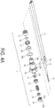
- FIG. 4A is a schematic exploded view illustrating a heating device and a safety device of a container according to a second embodiment of the present invention. Component parts and elements corresponding to those of FIG. 2 are designated by identical numeral references, and detailed descriptions thereof are omitted.
- the heating device 4' is a positive temperature coefficient (PTC) thermistor for effectively controlling the temperature in a safe range.
- PTC positive temperature coefficient
- FIG. 4B is a schematic cross-sectional view illustrating the combination of the heating device and the safety device of FIG 4A .
- FIG. 4C is a schematic right side view of FIG. 4B .
- the heating device 4' include an adapter 42, and the heating device 4' is assembled with the safety device 3 through the adapter 42. Consequently, the combination of the heating device 4' and the safety device 3 is substantially arranged in a line.
- the wiring part 41 of the heating device 4' is penetrated through the channel and the receptacle 301 of the main body 30 and protruded out of the safety device 3.
- the wiring part 41 is connected with an external power source (not shown).
- a supporting part 43 of the adapter 42 is fixed on the main body 30 of the safety device 3 through the packing nut 39 and the O ring 38. That is, the adapter 42 is connected with the main body 30 in a gas-tight manner.
- the gasket 31, the valve 32, the spring 33, the fusible plug block 34 and the hollow-type adjustment screw 35 with the flat part 351 and the slot part 352 are received within the receptacle 301.
- the hollow-type adjustment screw 35 has an external thread structure matching the inner thread structure of the receptacle 301. Through the hollow-type adjustment screw 35, the force of the spring 33 applied to the valve 32 is adjustable.
- the gasket 31, the valve 32, the spring 33 and the fusible plug block 34 are hollow structures.
- the outer diameters of the valve 32, the spring 33 and the fusible plug block 34 are smaller than the inner diameter of the receptacle 301. Consequently, the channel is defined by the gap between the inner surface of the receptacle 301 and the gasket 31, the valve 32, the spring 33 and the fusible plug block 34. The channel is used to exhaust gas.
- An intermediate concave segment of the main body 30 of the safety device 3 comprises the plural gas passageways 304.
- the filter 36 is arranged around the plural gas passageways 304 to cover the plural gas passageways 304. Moreover, the filter 36 is fixed on the main body 30 through the nut 37.
- the external thread structure 303 is engaged with the inner thread structure of the protrusion structure at the bottom end part 10 of the canister body 1. Consequently, the safety device 3 and the heating device 4' are securely fixed on the bottom end part 10 of the canister body 1.
- the heating device 4' is completely accommodated within the inner space 12 of the canister body 1. Consequently, the efficacy of the gas tightness is enhanced, and the gas in the canister body 1 does not leak out.
- the adapter 42 and the supporting part 43 are omitted. According to the practical requirements, the heating device 4 ' is an integral structure formed in one piece.
- FIG. 5A is a schematic exploded view illustrating a heating device and a safety device of a container according to a third embodiment of the present invention
- FIG. 5B is a schematic exploded view illustrating the heating device of FIG. 5A
- FIG. 5C is a schematic cross-sectional view illustrating the combination of the heating device and the safety device of FIG 5A
- FIG. 5D is a schematic right side view of FIG. 5C
- FIG 6 is a schematic cross-sectional view illustrating the assembled structure of the container according to the third embodiment of the present invention.
- Component parts and elements corresponding to those of FIGS. 4A to 4C are designated by identical numeral references, and detailed descriptions thereof are omitted.
- FIGS. 4A to 4C Component parts and elements corresponding to those of FIGS. 4A to 4C are designated by identical numeral references, and detailed descriptions thereof are omitted. In comparison with the second embodiment as shown in FIGS.
- the heating device 4" of this embodiment includes a heating element 4' having a wire part 41, an adapter 42 with a supporting part 43, a plug 44, a sleeve 45, two sealing rings 46 and a nut 47.
- the sleeve 45 is made of thermally-conductive material or metal material.
- the wire part 41 of the heating element 4' is penetrated through the plug 44 firstly, and then inserted into the sleeve 45, penetrated through one sealing ring 46 and the adapter 42 with the supporting part 43. Consequently, the wire part 41 is protruded out of the sleeve 45. Then, two ends of the sleeve 45 are assembled with the adapter 42 and the nut 47 through the sealing rings 46, respectively.
- the heating element 4' is installed in the interior of the sleeve 45 and sealed by the adapter 42 and the nut 47 so as to achieve the assembly of the heating device 4".
- the method and structure of assembling the heating device 4" and the safety device 3 are the same as that of the second embodiment of FIGS. 4A to 4C , and aren't described redundantly hereinafter.
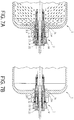
- FIG. 7A schematically illustrates the actions of the safety device of the container when the valve is opened.
- FIG. 7B schematically illustrates the actions of the safety device of the container when the valve is closed.
- the predetermined pressure value is in the range between 450 psi and 700 psi, preferably in the range between 500 psi and 650 psi, and more preferably 600 psi. If the charging pressure or the internal pressure is higher than the predetermined pressure value, the gas flows into the safety device 3 through the filter 36.
- the gas flows through the gas passageways 304, the gas pushes the gasket 31, the valve 32 and the spring 33.
- the spring 33 is compressed and the valve 32 is opened. Consequently, the gas quickly flows to the flat part 351 of the hollow-type adjustment screw 35 through the channel of the receptacle 301 and releases to the surroundings. Under this circumstance, the pressure is reduced.
- the spring 33 of the safety device 3 is no longer pushed by the gas. Consequently, the spring 33 is returned to its original position, and the gas passageways 304 are closed by the gasket 31 and the valve 32. As shown in FIG. 7B , the canister body 1 is not damaged, and the canister body 1 can be continuously charged with the gas.
- the predetermined temperature value is in the range between 100°C and 140°C, preferably in the range between 110°C and 130°C, and more preferably 120°C.
- the heating device 4 is out of control, and the temperature is higher than the predetermined temperature value.
- the valve 32 is not activated or opened.
- the fusible plug block 34 is gradually molten.
- the fusible plug block 34 As the fusible plug block 34 is gradually molten, the area of the fusible plug block 34 to sustain against the spring 33 is gradually lost.
- the gasket 31 and the valve 32 are not pushed by the spring 33, the gasket 31 and the valve 32 are pushed by the gas and the valve 32 is opened. Consequently, the gas quickly flows to the flat part 351 of the hollow-type adjustment screw 35 through the channel of the receptacle 301 and releases to the surroundings. Under this circumstance, the pressure is reduced. Moreover, if the external flame is applied to the container, the above safety measurement is also taken.
- FIG. 8 schematically illustrates a first example of connecting the container with an external power source.
- the canister body 1 is placed within a water jacket 5.
- the bottom end part of the canister body 1 is connected with a handle 6.
- the handle 6 comprises conducting slices 60.
- the wiring part 41 of the heating device 4 is connected with the conducting slices 60 of the handle 6 through a welding means or a conducting element.
- a power supply unit 7 with an automatic temperature control function is connected with an end 50 of the water jacket 5.
- the power supply unit 7 is connected with an electromagnet 72 through a bracket 71.
- An end of the electromagnet 72 is fixed on the bracket 71 through a nut 73.
- An elastic strip seat 74 is fixed on the bracket 71 through an outer shell 741.
- conductive elastic strips 742 are received in an end of the spring strip seat 74 and connected with a power control unit 79.
- a movable post 721 of the electromagnet 72 is connected with the elastic strip seat 74 through a fastening ring 75 and a push plate 76.
- the conducting slices 60 of the handle 6 are in front of the spring strip seat 74.
- the movable post 721 of the electromagnet 72 is moved forwardly.
- the conductive elastic strips 742 of the elastic strip seat 74 are connected with the conducting slices 60 of the handle 6.
- the heating device 4 within the canister body 1 is powered on (see FIG. 9A ).
- the movable post 721 of the electromagnet 72 is retracted backwardly, the conductive elastic strips 742 of the elastic strip seat 74 are disconnected from the conducting slices 60 of the handle 6. Consequently, the heating device 4 within the canister body 1 is powered off (see FIG. 9B ).
- the power supply unit 7 provides electric energy according to wireless electromagnetic induction, radio waves or nuclear magnetic resonance.
- the handle of the container is in communication with a database according to a RFID technology. Consequently, the specification of the container, the type of the stored gas, the number of use times and the maintenance history are recorded in the database.
- FIG. 10 schematically illustrates an example of connecting the heating device with the handle.
- the square handle 8 has two ring-shaped conducting slices 81 corresponding to the junction between the canister body 1, the safety device 3 and the heating device 4 in order to be electrically connected with the external power source.
- FIG. 11 schematically illustrates another example of connecting the heating device with the handle.
- the circular handle 9 has two ring-shaped conducting slices 91 corresponding to the junction between the canister body 1, the safety device 3 and the heating device 4 in order to be electrically connected with the external power source.
- FIGS. 12A and 12B schematically illustrate a second example of connecting the container with an external power source.
- Two power supply units 7' with the automatic temperature control function are connected with the end of the water jacket 5.
- the conductive elastic strips 78 at an end of the linkage lever 77 are tightly contacted with the conducting slices 81 of the square handle 8. Consequently, the heating device 4 within the canister body 1 is powered on (see FIG. 12A ).
- the linkage lever 77 is moved upwardly or unlocked, the conductive elastic strips 78 are disconnected from the conducting slices 81 of the square handle 8. Consequently, the heating device 4 within the canister body 1 is powered off (see FIG. 12B ).
- FIGS. 13A and 13B schematically illustrate a third example of connecting the container with an external power source.
- Two power supply units 7" with the automatic temperature control function are connected with the end of the water jacket 5.
- the conductive elastic strips 78' at an end of the linkage lever 77' are tightly contacted with the conducting slices 91 of the circular handle 9. Consequently, the heating device 4 within the canister body 1 is powered on (see FIG. 13A ).
- the linkage lever 77' is moved upwardly or unlocked, the conductive elastic strips 78 are disconnected from the conducting slices 91 of the circular handle 9. Consequently, the heating device 4 within the canister body 1 is powered off (see FIG. 13B ).
- FIG. 14 is a schematic perspective view illustrating the outer appearance of a container according to a third embodiment of the present invention.
- the container comprises a canister body 1, a quick connection terminal 2, two safety devices 3 and two heating devices (not shown).
- the drawbacks of the conventional technology e.g., the unsuccessful cold start problem
- the container of the present invention can be operated and used in a simplified manner. Since the gas storage material is uniformly and stably heated, the efficiency of charging/discharging the gas (e.g., hydrogen gas) is enhanced. Moreover, the installation of the safety device can protect the canister body.
- the gas e.g., hydrogen gas
- the predetermined pressure value or the predetermined temperature value may be varied according to the practical conditions and environments. For example, if external flame is applied to the container, the protecting mechanism is enabled when the temperature reaches the predetermined temperature value. As the temperature increases, the internal pressure of the canister body also increases. When the pressure reaches the predetermined pressure value, the protecting mechanism is also enabled.
- the manufacturer has to set the suitable predetermined pressure value and the suitable predetermined temperature value to have the container comply with the environmental conditions. In the above embodiment, the most preferred predetermined pressure value is 600 psi and the most predetermined temperature value is 120°C. It is noted that these values may be varied according to the environmental conditions.
Landscapes
- Chemical & Material Sciences (AREA)
- Chemical Kinetics & Catalysis (AREA)
- Organic Chemistry (AREA)
- Engineering & Computer Science (AREA)
- Life Sciences & Earth Sciences (AREA)
- Manufacturing & Machinery (AREA)
- Sustainable Development (AREA)
- Sustainable Energy (AREA)
- Electrochemistry (AREA)
- General Chemical & Material Sciences (AREA)
- General Engineering & Computer Science (AREA)
- Combustion & Propulsion (AREA)
- Inorganic Chemistry (AREA)
- Mechanical Engineering (AREA)
- Filling Or Discharging Of Gas Storage Vessels (AREA)
- Fuel Cell (AREA)
Claims (14)
- Behälter, umfassend:einen Behälterkörper (1) mit einem Innenraum (12) zum Lagern von Metallhydrid;mindestens eine Heizeinrichtung (4, 4', 4''), die innerhalb des Innenraums (12) des Behälterkörpers (1) zum Erwärmen des Metallhydrids untergebracht ist, so dass das Metallhydrid Wasserstoff freisetzt; undmindestens eine Sicherheitsvorrichtung (3), die an einem Endteil des Behälterkörpers (1) installiert ist,dadurch gekennzeichnet, dass die Sicherheitseinrichtung (3) mit der entsprechenden Heizeinrichtung (4, 4', 4'') verbunden ist, wobei die Heizeinrichtung (4, 4', 4") einen Drahtteil (41) aufweist, wobei die Sicherheitseinrichtung (3) einen Hauptkörper (30) mit einer Aufnahme (301) umfasst, wobei der Drahtteil (41) der Heizeinrichtung (4, 4', 4'') durch die Aufnahme (301) des Hauptkörpers (30) verläuft, um aus der Sicherheitsvorrichtung (3) herauszuragen, wobei die Aufnahme (301) des Hauptkörpers (30) dazu konfiguriert ist, den Wasserstoff freizusetzen, während eine Temperatur des Innenraums (12) höher als eine vorbestimmte Temperatur ist oder ein Druck des Innenraums (12) höher ist als ein vorbestimmter Druckwert.
- Behälter nach Anspruch 1, wobei die Heizeinrichtung (4, 4', 4'') entweder eine elektrische Heizleiste, ein Thermistor mit positivem Temperaturkoeffizienten oder eine Heizung ist.
- Behälter nach Anspruch 2, dadurch gekennzeichnet, dass ein Heizkörper der Heizeinrichtung (4, 4', 4'') von einer wärmeleitenden Metallschicht bedeckt ist.
- Behälter nach Anspruch 2, dadurch gekennzeichnet, dass die Heizeinrichtung (4, 4', 4'') einen Adapter (42) aufweist und die Heizeinrichtung (4, 4', 4") mit der Sicherheitseinrichtung (3) durch den Adapter (42) zusammengesetzt ist.
- Behälter nach Anspruche 1, dadurch gekennzeichnet, dass die Heizeinrichtung (4, 4', 4'') umfasst:eine Hülse (45);einen Stecker (44);mindestens zwei Dichtungsringe (46);einen Adapter (42) mit einem Stützteil (43);eine Mutter (47); undein Heizelement (4') mit einem Drahtteil (41), wobei der Drahtteil (41) des Heizelements (4') durch den Stopfen (44) dringt und dann in die Hülse (45) eingeführt ist, einen der beiden Dichtringe (46) und den Adapter (42) mit dem Stützteil (43) durchdringt und aus der Hülse (45) herausragt, wobei zwei Enden der Hülse (45) mit dem Adapter (42 ) und der Mutter (47) durch die beiden Dichtringe (46) zusammengesetzt sind, so dass das Heizelement (4') in einem Inneren der Hülse (45) installiert und durch den Adapter (42) und die Mutter (47) abgedichtet ist.
- Behälter nach Anspruch 1, dadurch gekennzeichnet, dass die Sicherheitseinrichtung (3) einen Hauptkörper (30) mit einer Aufnahme (301) aufweist, wobei eine Dichtung (31), ein Ventil (32), eine Feder (33), ein schmelzbarer Stopfenblock (34) und eine hohle Einstellschraube (35) in der Aufnahme (301) aufgenommen sind; und die hohle Einstellschraube (35) einen flachen Teil (351) und einen Schlitzteil (352) umfasst.
- Behälter nach Anspruch 6, dadurch gekennzeichnet, dass ein äußerer Durchmesser von jeder der Dichtung (31), des Ventils (32), der Feder (33) und des schmelzbaren Stopfenblocks (34) kleiner ist als ein innerer Durchmesser der Aufnahme (301), so dass ein Kanal durch einen Spalt zwischen einer Innenfläche der Aufnahme (301) und der Dichtung (31), dem Ventil (32), der Feder (33) und dem schmelzbaren Stopfenblock (34) definiert ist.
- Behälter nach Anspruch 7, dadurch gekennzeichnet, dass wenn die Temperatur höher als der vorbestimmte Temperaturwert oder der Druck höher als der vorbestimmte Druckwert ist, ein Teil des Wasserstoffs durch den Kanal zu einer Außenseite der Sicherheitseinrichtung (3) freigesetzt wird.
- Behälter nach Anspruch 6, 7 oder 8, dadurch gekennzeichnet, dass wenn die Temperatur des Innenraums (12) den vorbestimmten Temperaturwert erreicht, der schmelzbare Stopfenblock (34) geschmolzen ist.
- Behälter nach den Ansprüchen 1 oder 6, dadurch gekennzeichnet, dass die Sicherheitseinrichtung (3) einen O-Ring (38) und eine Packungsmutter (39) aufweist und die Heizeinrichtung (4) an der Sicherheitseinrichtung (3) durch den O-Ring (38) und die Packungsmutter (39) befestigt ist.
- Behälter nach Anspruch 1 oder 6, dadurch gekennzeichnet, dass ein Zwischensegment des Hauptkörpers (30) der Sicherheitseinrichtung (3) mehrere Gasdurchgänge (304) aufweist.
- Behälter nach Anspruch 11, dadurch gekennzeichnet, dass die Sicherheitseinrichtung (3) ferner einen Filter (36) umfasst und der Filter (36) um die mehreren Gasdurchgänge (304) angeordnet ist, um die mehreren Gasdurchgänge (304) abzudecken.
- Behälter nach Anspruche 1, dadurch gekennzeichnet, dass der Endteil des Behälterkörpers (1) weiterhin mit einem Griff (6, 8, 9) verbunden ist und der Behälter elektrisch durch den Griff (6, 8, 9) mit einer Stromversorgungseinheit (7) verbunden ist.
- Behälter nach einem der Ansprüche 1 bis 13, dadurch gekennzeichnet, dass der Behälter ein Gasspeicherbehälter oder ein Wasserstoffspeicherbehälter ist.
Applications Claiming Priority (1)
| Application Number | Priority Date | Filing Date | Title |
|---|---|---|---|
| TW104127411A TWI591890B (zh) | 2015-08-21 | 2015-08-21 | 容器之加熱及安全裝置、氣體儲存罐及儲氫罐 |
Publications (2)
| Publication Number | Publication Date |
|---|---|
| EP3133687A1 EP3133687A1 (de) | 2017-02-22 |
| EP3133687B1 true EP3133687B1 (de) | 2018-11-21 |
Family
ID=56990213
Family Applications (1)
| Application Number | Title | Priority Date | Filing Date |
|---|---|---|---|
| EP16184847.8A Active EP3133687B1 (de) | 2015-08-21 | 2016-08-19 | Behälter mit heizvorrichtung und sicherheitsvorrichtung |
Country Status (4)
| Country | Link |
|---|---|
| US (1) | US10532337B2 (de) |
| EP (1) | EP3133687B1 (de) |
| JP (1) | JP7075104B2 (de) |
| TW (1) | TWI591890B (de) |
Families Citing this family (4)
| Publication number | Priority date | Publication date | Assignee | Title |
|---|---|---|---|---|
| DE102018206345A1 (de) * | 2018-04-25 | 2019-10-31 | Robert Bosch Gmbh | Schmelzsicherung, Gasbehälter und Verfahren zum Zusammenbauen einer Schmelzsicherung und zum Einbauen derselben in einen Gasbehälter |
| DE102020201172A1 (de) * | 2020-01-31 | 2021-08-05 | Robert Bosch Gesellschaft mit beschränkter Haftung | Vorrichtung zum Speichern von Druckgas, Fahrzeug |
| CN113566106A (zh) * | 2021-06-09 | 2021-10-29 | 黄冈格罗夫氢能汽车有限公司 | 一种气瓶高温泄压系统及氢能汽车 |
| CN118041705B (zh) * | 2024-04-12 | 2024-06-07 | 成都纵横智控科技有限公司 | 一种基于工业互联网智能终端的安全管理装置 |
Family Cites Families (12)
| Publication number | Priority date | Publication date | Assignee | Title |
|---|---|---|---|---|
| DE10105895A1 (de) * | 2001-02-09 | 2002-08-29 | Bosch Gmbh Robert | Einrichtung zur Abgabe von Wasserstoff |
| TW499777B (en) | 2001-04-16 | 2002-08-21 | Asia Pacific Fuel Cell Tech | Supply device for use with hydrogen source |
| US7122261B2 (en) | 2003-02-21 | 2006-10-17 | The Regents Of The University Of California | Metal hydride fuel storage and method thereof |
| US7712794B2 (en) * | 2003-05-02 | 2010-05-11 | Asia Pacific Fuel Cell Technologies, Ltd. | Rapid coupling device for hydrogen storage canister |
| JP4729674B2 (ja) | 2004-03-31 | 2011-07-20 | 太平洋セメント株式会社 | 水素貯蔵タンクおよびこれを搭載した移動体 |
| US7537748B2 (en) * | 2003-08-11 | 2009-05-26 | National University Corporation, Hiroshima University | Hydrogen storage matter and manufacturing method and apparatus for the same |
| JP2009138904A (ja) | 2007-12-10 | 2009-06-25 | Toyota Motor Corp | ガスタンク |
| US8454730B2 (en) | 2010-04-20 | 2013-06-04 | GM Global Technology Operations LLC | Method of operating gas storage and supply system |
| US8875495B2 (en) * | 2010-08-06 | 2014-11-04 | GM Global Technology Operations LLC | Tank assembly and method |
| JP5536680B2 (ja) * | 2011-01-13 | 2014-07-02 | 株式会社村上開明堂 | ウォッシャー液の加温装置 |
| WO2013191575A1 (en) | 2012-06-19 | 2013-12-27 | Simens Aktiengellschaft | Closing device for a tank |
| SG2013022967A (en) * | 2013-03-25 | 2014-10-30 | Horizon Energy Systems Pte Ltd | Method and generator for hydrogen production |
-
2015
- 2015-08-21 TW TW104127411A patent/TWI591890B/zh active
-
2016
- 2016-08-19 US US15/241,734 patent/US10532337B2/en active Active
- 2016-08-19 EP EP16184847.8A patent/EP3133687B1/de active Active
- 2016-08-22 JP JP2016161860A patent/JP7075104B2/ja active Active
Non-Patent Citations (1)
| Title |
|---|
| None * |
Also Published As
| Publication number | Publication date |
|---|---|
| US10532337B2 (en) | 2020-01-14 |
| TWI591890B (zh) | 2017-07-11 |
| EP3133687A1 (de) | 2017-02-22 |
| US20170050160A1 (en) | 2017-02-23 |
| TW201709600A (zh) | 2017-03-01 |
| JP7075104B2 (ja) | 2022-05-25 |
| JP2017040371A (ja) | 2017-02-23 |
Similar Documents
| Publication | Publication Date | Title |
|---|---|---|
| US10532337B2 (en) | Container with heating device and safety device | |
| EP1722152B1 (de) | Druckbetriebenes Kühlsystem zur Steigerung der Nachfüllungsgeschwindigkeit und der Kapazität von Hochdruckgasbehältern in Kraftfahrzeugen | |
| EP2754946B1 (de) | Vorrichtung zur Verbesserung der Effizienz von Hochdrucklagertanks für komprimiertes Erdgas oder Wasserstoffkraftstoff | |
| JP4594149B2 (ja) | 圧縮ガス貯蔵装置 | |
| EP2361797B1 (de) | Gastank | |
| EP2227651B1 (de) | Erwärmungssysteme für hochdruck-gassspeichervorrichtungen | |
| EP2920836B1 (de) | Wasserstoffgenerator und verfahren zur bereitstellung von wasserstoffgas | |
| CN112606712A (zh) | 一种用于储氢装置的温度控制系统、方法及氢能源助力车 | |
| JP2008190658A (ja) | 水素充填装置 | |
| KR102148527B1 (ko) | 온도 퓨즈에 대한 단열 차폐 구조를 갖는 배터리용 냉각수 가열 장치 | |
| CN104913186A (zh) | 气体收容罐 | |
| US20090142636A1 (en) | Carbon Fiber Warming System for Fiber Composite Gas Storage Cylinders | |
| CN213920694U (zh) | 一种储氢装置及氢能源助力车 | |
| CN112879794A (zh) | 一种低压安全储氢器及氢燃料电动自行车 | |
| CN113028270B (zh) | 一种带有身份识别的储氢器及氢燃料电动自行车 | |
| CN215372025U (zh) | 一种低压安全储氢器及氢燃料电动自行车 | |
| CN106469817A (zh) | 容器的加热及安全装置、气体储存罐及储氢罐 | |
| US10093538B2 (en) | Heater assembly, hydrogen generator and method of providing hydrogen gas | |
| CA2898280A1 (en) | Heater with replaceable cartridge | |
| JP2023079990A (ja) | ノズル加熱装置および流体充填システム | |
| WO2021213501A1 (zh) | 储氢装置、安全装置、储氢系统、温控系统、温控方法及氢动力车 | |
| CN214038953U (zh) | 一种防爆电加热器 | |
| US20150064104A1 (en) | Hydrogen generator with sequential fuel initiation | |
| EP3351761A1 (de) | Ammoniakspeichertank und verwendung davon | |
| KR20240076292A (ko) | 차량용 냉각수 가열장치 |
Legal Events
| Date | Code | Title | Description |
|---|---|---|---|
| PUAI | Public reference made under article 153(3) epc to a published international application that has entered the european phase |
Free format text: ORIGINAL CODE: 0009012 |
|
| STAA | Information on the status of an ep patent application or granted ep patent |
Free format text: STATUS: THE APPLICATION HAS BEEN PUBLISHED |
|
| AK | Designated contracting states |
Kind code of ref document: A1 Designated state(s): AL AT BE BG CH CY CZ DE DK EE ES FI FR GB GR HR HU IE IS IT LI LT LU LV MC MK MT NL NO PL PT RO RS SE SI SK SM TR |
|
| AX | Request for extension of the european patent |
Extension state: BA ME |
|
| STAA | Information on the status of an ep patent application or granted ep patent |
Free format text: STATUS: REQUEST FOR EXAMINATION WAS MADE |
|
| 17P | Request for examination filed |
Effective date: 20170822 |
|
| RBV | Designated contracting states (corrected) |
Designated state(s): AL AT BE BG CH CY CZ DE DK EE ES FI FR GB GR HR HU IE IS IT LI LT LU LV MC MK MT NL NO PL PT RO RS SE SI SK SM TR |
|
| STAA | Information on the status of an ep patent application or granted ep patent |
Free format text: STATUS: EXAMINATION IS IN PROGRESS |
|
| 17Q | First examination report despatched |
Effective date: 20171025 |
|
| INTG | Intention to grant announced |
Effective date: 20180611 |
|
| GRAP | Despatch of communication of intention to grant a patent |
Free format text: ORIGINAL CODE: EPIDOSNIGR1 |
|
| STAA | Information on the status of an ep patent application or granted ep patent |
Free format text: STATUS: GRANT OF PATENT IS INTENDED |
|
| GRAS | Grant fee paid |
Free format text: ORIGINAL CODE: EPIDOSNIGR3 |
|
| GRAA | (expected) grant |
Free format text: ORIGINAL CODE: 0009210 |
|
| STAA | Information on the status of an ep patent application or granted ep patent |
Free format text: STATUS: THE PATENT HAS BEEN GRANTED |
|
| AK | Designated contracting states |
Kind code of ref document: B1 Designated state(s): AL AT BE BG CH CY CZ DE DK EE ES FI FR GB GR HR HU IE IS IT LI LT LU LV MC MK MT NL NO PL PT RO RS SE SI SK SM TR |
|
| REG | Reference to a national code |
Ref country code: CH Ref legal event code: EP |
|
| REG | Reference to a national code |
Ref country code: IE Ref legal event code: FG4D |
|
| REG | Reference to a national code |
Ref country code: AT Ref legal event code: REF Ref document number: 1068595 Country of ref document: AT Kind code of ref document: T Effective date: 20181215 |
|
| REG | Reference to a national code |
Ref country code: DE Ref legal event code: R096 Ref document number: 602016007339 Country of ref document: DE |
|
| REG | Reference to a national code |
Ref country code: NL Ref legal event code: MP Effective date: 20181121 |
|
| REG | Reference to a national code |
Ref country code: AT Ref legal event code: MK05 Ref document number: 1068595 Country of ref document: AT Kind code of ref document: T Effective date: 20181121 |
|
| PG25 | Lapsed in a contracting state [announced via postgrant information from national office to epo] |
Ref country code: FI Free format text: LAPSE BECAUSE OF FAILURE TO SUBMIT A TRANSLATION OF THE DESCRIPTION OR TO PAY THE FEE WITHIN THE PRESCRIBED TIME-LIMIT Effective date: 20181121 Ref country code: LV Free format text: LAPSE BECAUSE OF FAILURE TO SUBMIT A TRANSLATION OF THE DESCRIPTION OR TO PAY THE FEE WITHIN THE PRESCRIBED TIME-LIMIT Effective date: 20181121 Ref country code: HR Free format text: LAPSE BECAUSE OF FAILURE TO SUBMIT A TRANSLATION OF THE DESCRIPTION OR TO PAY THE FEE WITHIN THE PRESCRIBED TIME-LIMIT Effective date: 20181121 Ref country code: AT Free format text: LAPSE BECAUSE OF FAILURE TO SUBMIT A TRANSLATION OF THE DESCRIPTION OR TO PAY THE FEE WITHIN THE PRESCRIBED TIME-LIMIT Effective date: 20181121 Ref country code: BG Free format text: LAPSE BECAUSE OF FAILURE TO SUBMIT A TRANSLATION OF THE DESCRIPTION OR TO PAY THE FEE WITHIN THE PRESCRIBED TIME-LIMIT Effective date: 20190221 Ref country code: LT Free format text: LAPSE BECAUSE OF FAILURE TO SUBMIT A TRANSLATION OF THE DESCRIPTION OR TO PAY THE FEE WITHIN THE PRESCRIBED TIME-LIMIT Effective date: 20181121 Ref country code: ES Free format text: LAPSE BECAUSE OF FAILURE TO SUBMIT A TRANSLATION OF THE DESCRIPTION OR TO PAY THE FEE WITHIN THE PRESCRIBED TIME-LIMIT Effective date: 20181121 Ref country code: IS Free format text: LAPSE BECAUSE OF FAILURE TO SUBMIT A TRANSLATION OF THE DESCRIPTION OR TO PAY THE FEE WITHIN THE PRESCRIBED TIME-LIMIT Effective date: 20190321 Ref country code: NO Free format text: LAPSE BECAUSE OF FAILURE TO SUBMIT A TRANSLATION OF THE DESCRIPTION OR TO PAY THE FEE WITHIN THE PRESCRIBED TIME-LIMIT Effective date: 20190221 |
|
| PG25 | Lapsed in a contracting state [announced via postgrant information from national office to epo] |
Ref country code: AL Free format text: LAPSE BECAUSE OF FAILURE TO SUBMIT A TRANSLATION OF THE DESCRIPTION OR TO PAY THE FEE WITHIN THE PRESCRIBED TIME-LIMIT Effective date: 20181121 Ref country code: RS Free format text: LAPSE BECAUSE OF FAILURE TO SUBMIT A TRANSLATION OF THE DESCRIPTION OR TO PAY THE FEE WITHIN THE PRESCRIBED TIME-LIMIT Effective date: 20181121 Ref country code: NL Free format text: LAPSE BECAUSE OF FAILURE TO SUBMIT A TRANSLATION OF THE DESCRIPTION OR TO PAY THE FEE WITHIN THE PRESCRIBED TIME-LIMIT Effective date: 20181121 Ref country code: PT Free format text: LAPSE BECAUSE OF FAILURE TO SUBMIT A TRANSLATION OF THE DESCRIPTION OR TO PAY THE FEE WITHIN THE PRESCRIBED TIME-LIMIT Effective date: 20190321 Ref country code: GR Free format text: LAPSE BECAUSE OF FAILURE TO SUBMIT A TRANSLATION OF THE DESCRIPTION OR TO PAY THE FEE WITHIN THE PRESCRIBED TIME-LIMIT Effective date: 20190222 Ref country code: SE Free format text: LAPSE BECAUSE OF FAILURE TO SUBMIT A TRANSLATION OF THE DESCRIPTION OR TO PAY THE FEE WITHIN THE PRESCRIBED TIME-LIMIT Effective date: 20181121 |
|
| PG25 | Lapsed in a contracting state [announced via postgrant information from national office to epo] |
Ref country code: CZ Free format text: LAPSE BECAUSE OF FAILURE TO SUBMIT A TRANSLATION OF THE DESCRIPTION OR TO PAY THE FEE WITHIN THE PRESCRIBED TIME-LIMIT Effective date: 20181121 Ref country code: IT Free format text: LAPSE BECAUSE OF FAILURE TO SUBMIT A TRANSLATION OF THE DESCRIPTION OR TO PAY THE FEE WITHIN THE PRESCRIBED TIME-LIMIT Effective date: 20181121 Ref country code: PL Free format text: LAPSE BECAUSE OF FAILURE TO SUBMIT A TRANSLATION OF THE DESCRIPTION OR TO PAY THE FEE WITHIN THE PRESCRIBED TIME-LIMIT Effective date: 20181121 Ref country code: DK Free format text: LAPSE BECAUSE OF FAILURE TO SUBMIT A TRANSLATION OF THE DESCRIPTION OR TO PAY THE FEE WITHIN THE PRESCRIBED TIME-LIMIT Effective date: 20181121 |
|
| REG | Reference to a national code |
Ref country code: DE Ref legal event code: R097 Ref document number: 602016007339 Country of ref document: DE |
|
| PG25 | Lapsed in a contracting state [announced via postgrant information from national office to epo] |
Ref country code: SM Free format text: LAPSE BECAUSE OF FAILURE TO SUBMIT A TRANSLATION OF THE DESCRIPTION OR TO PAY THE FEE WITHIN THE PRESCRIBED TIME-LIMIT Effective date: 20181121 Ref country code: EE Free format text: LAPSE BECAUSE OF FAILURE TO SUBMIT A TRANSLATION OF THE DESCRIPTION OR TO PAY THE FEE WITHIN THE PRESCRIBED TIME-LIMIT Effective date: 20181121 Ref country code: SK Free format text: LAPSE BECAUSE OF FAILURE TO SUBMIT A TRANSLATION OF THE DESCRIPTION OR TO PAY THE FEE WITHIN THE PRESCRIBED TIME-LIMIT Effective date: 20181121 Ref country code: RO Free format text: LAPSE BECAUSE OF FAILURE TO SUBMIT A TRANSLATION OF THE DESCRIPTION OR TO PAY THE FEE WITHIN THE PRESCRIBED TIME-LIMIT Effective date: 20181121 |
|
| PLBE | No opposition filed within time limit |
Free format text: ORIGINAL CODE: 0009261 |
|
| STAA | Information on the status of an ep patent application or granted ep patent |
Free format text: STATUS: NO OPPOSITION FILED WITHIN TIME LIMIT |
|
| 26N | No opposition filed |
Effective date: 20190822 |
|
| PG25 | Lapsed in a contracting state [announced via postgrant information from national office to epo] |
Ref country code: SI Free format text: LAPSE BECAUSE OF FAILURE TO SUBMIT A TRANSLATION OF THE DESCRIPTION OR TO PAY THE FEE WITHIN THE PRESCRIBED TIME-LIMIT Effective date: 20181121 |
|
| PG25 | Lapsed in a contracting state [announced via postgrant information from national office to epo] |
Ref country code: TR Free format text: LAPSE BECAUSE OF FAILURE TO SUBMIT A TRANSLATION OF THE DESCRIPTION OR TO PAY THE FEE WITHIN THE PRESCRIBED TIME-LIMIT Effective date: 20181121 |
|
| PG25 | Lapsed in a contracting state [announced via postgrant information from national office to epo] |
Ref country code: CH Free format text: LAPSE BECAUSE OF NON-PAYMENT OF DUE FEES Effective date: 20190831 Ref country code: MC Free format text: LAPSE BECAUSE OF FAILURE TO SUBMIT A TRANSLATION OF THE DESCRIPTION OR TO PAY THE FEE WITHIN THE PRESCRIBED TIME-LIMIT Effective date: 20181121 Ref country code: LU Free format text: LAPSE BECAUSE OF NON-PAYMENT OF DUE FEES Effective date: 20190819 Ref country code: LI Free format text: LAPSE BECAUSE OF NON-PAYMENT OF DUE FEES Effective date: 20190831 |
|
| REG | Reference to a national code |
Ref country code: BE Ref legal event code: MM Effective date: 20190831 |
|
| PG25 | Lapsed in a contracting state [announced via postgrant information from national office to epo] |
Ref country code: IE Free format text: LAPSE BECAUSE OF NON-PAYMENT OF DUE FEES Effective date: 20190819 |
|
| PG25 | Lapsed in a contracting state [announced via postgrant information from national office to epo] |
Ref country code: BE Free format text: LAPSE BECAUSE OF NON-PAYMENT OF DUE FEES Effective date: 20190831 |
|
| PG25 | Lapsed in a contracting state [announced via postgrant information from national office to epo] |
Ref country code: CY Free format text: LAPSE BECAUSE OF FAILURE TO SUBMIT A TRANSLATION OF THE DESCRIPTION OR TO PAY THE FEE WITHIN THE PRESCRIBED TIME-LIMIT Effective date: 20181121 |
|
| PG25 | Lapsed in a contracting state [announced via postgrant information from national office to epo] |
Ref country code: HU Free format text: LAPSE BECAUSE OF FAILURE TO SUBMIT A TRANSLATION OF THE DESCRIPTION OR TO PAY THE FEE WITHIN THE PRESCRIBED TIME-LIMIT; INVALID AB INITIO Effective date: 20160819 Ref country code: MT Free format text: LAPSE BECAUSE OF FAILURE TO SUBMIT A TRANSLATION OF THE DESCRIPTION OR TO PAY THE FEE WITHIN THE PRESCRIBED TIME-LIMIT Effective date: 20181121 |
|
| PG25 | Lapsed in a contracting state [announced via postgrant information from national office to epo] |
Ref country code: MK Free format text: LAPSE BECAUSE OF FAILURE TO SUBMIT A TRANSLATION OF THE DESCRIPTION OR TO PAY THE FEE WITHIN THE PRESCRIBED TIME-LIMIT Effective date: 20181121 |
|
| PGFP | Annual fee paid to national office [announced via postgrant information from national office to epo] |
Ref country code: DE Payment date: 20250724 Year of fee payment: 10 |
|
| PGFP | Annual fee paid to national office [announced via postgrant information from national office to epo] |
Ref country code: GB Payment date: 20250725 Year of fee payment: 10 |
|
| REG | Reference to a national code |
Ref country code: DE Ref legal event code: R081 Ref document number: 602016007339 Country of ref document: DE Owner name: AGRACE FUEL CELL TECHNOLOGY CO., TW Free format text: FORMER OWNER: ASIA PACIFIC FUEL CELL TECHNOLOGIES, LTD., CHUNAN, MIAOLI, TW Ref country code: DE Ref legal event code: R082 Ref document number: 602016007339 Country of ref document: DE |
|
| PGFP | Annual fee paid to national office [announced via postgrant information from national office to epo] |
Ref country code: FR Payment date: 20250725 Year of fee payment: 10 |
|
| REG | Reference to a national code |
Ref country code: GB Ref legal event code: 732E Free format text: REGISTERED BETWEEN 20251023 AND 20251029 |