EP3133676B1 - Method of manufacturing an electrical connector - Google Patents
Method of manufacturing an electrical connector Download PDFInfo
- Publication number
- EP3133676B1 EP3133676B1 EP16185155.5A EP16185155A EP3133676B1 EP 3133676 B1 EP3133676 B1 EP 3133676B1 EP 16185155 A EP16185155 A EP 16185155A EP 3133676 B1 EP3133676 B1 EP 3133676B1
- Authority
- EP
- European Patent Office
- Prior art keywords
- connection part
- terminal connection
- battery terminal
- plating
- battery
- Prior art date
- Legal status (The legal status is an assumption and is not a legal conclusion. Google has not performed a legal analysis and makes no representation as to the accuracy of the status listed.)
- Active
Links
- 238000004519 manufacturing process Methods 0.000 title claims description 41
- 238000000034 method Methods 0.000 claims description 72
- 230000008569 process Effects 0.000 claims description 51
- 238000007747 plating Methods 0.000 claims description 45
- 229910052751 metal Inorganic materials 0.000 claims description 26
- 239000002184 metal Substances 0.000 claims description 26
- PXHVJJICTQNCMI-UHFFFAOYSA-N Nickel Chemical compound [Ni] PXHVJJICTQNCMI-UHFFFAOYSA-N 0.000 claims description 19
- 239000010949 copper Substances 0.000 claims description 15
- 230000000873 masking effect Effects 0.000 claims description 13
- RYGMFSIKBFXOCR-UHFFFAOYSA-N Copper Chemical compound [Cu] RYGMFSIKBFXOCR-UHFFFAOYSA-N 0.000 claims description 10
- 229910052802 copper Inorganic materials 0.000 claims description 10
- 239000010931 gold Substances 0.000 claims description 10
- 238000010168 coupling process Methods 0.000 claims description 8
- 230000008878 coupling Effects 0.000 claims description 7
- 238000005859 coupling reaction Methods 0.000 claims description 7
- 229910052759 nickel Inorganic materials 0.000 claims description 7
- ATJFFYVFTNAWJD-UHFFFAOYSA-N Tin Chemical compound [Sn] ATJFFYVFTNAWJD-UHFFFAOYSA-N 0.000 claims description 6
- 238000003825 pressing Methods 0.000 claims description 6
- PCHJSUWPFVWCPO-UHFFFAOYSA-N gold Chemical compound [Au] PCHJSUWPFVWCPO-UHFFFAOYSA-N 0.000 claims description 5
- 229910052737 gold Inorganic materials 0.000 claims description 5
- 229910000838 Al alloy Inorganic materials 0.000 claims description 4
- 229910000881 Cu alloy Inorganic materials 0.000 claims description 4
- 229910052782 aluminium Inorganic materials 0.000 claims description 4
- XAGFODPZIPBFFR-UHFFFAOYSA-N aluminium Chemical compound [Al] XAGFODPZIPBFFR-UHFFFAOYSA-N 0.000 claims description 4
- 239000007769 metal material Substances 0.000 claims 9
- 238000003466 welding Methods 0.000 claims 1
- 238000005253 cladding Methods 0.000 description 2
- 238000004140 cleaning Methods 0.000 description 2
- 239000004020 conductor Substances 0.000 description 2
- 238000005516 engineering process Methods 0.000 description 2
- 150000002739 metals Chemical class 0.000 description 2
- 230000005540 biological transmission Effects 0.000 description 1
- 238000007796 conventional method Methods 0.000 description 1
- 230000001934 delay Effects 0.000 description 1
- 230000005611 electricity Effects 0.000 description 1
- 238000009713 electroplating Methods 0.000 description 1
- 238000012986 modification Methods 0.000 description 1
- 230000004048 modification Effects 0.000 description 1
Images


Classifications
-
- C—CHEMISTRY; METALLURGY
- C25—ELECTROLYTIC OR ELECTROPHORETIC PROCESSES; APPARATUS THEREFOR
- C25D—PROCESSES FOR THE ELECTROLYTIC OR ELECTROPHORETIC PRODUCTION OF COATINGS; ELECTROFORMING; APPARATUS THEREFOR
- C25D5/00—Electroplating characterised by the process; Pretreatment or after-treatment of workpieces
- C25D5/02—Electroplating of selected surface areas
- C25D5/022—Electroplating of selected surface areas using masking means
-
- C—CHEMISTRY; METALLURGY
- C25—ELECTROLYTIC OR ELECTROPHORETIC PROCESSES; APPARATUS THEREFOR
- C25D—PROCESSES FOR THE ELECTROLYTIC OR ELECTROPHORETIC PRODUCTION OF COATINGS; ELECTROFORMING; APPARATUS THEREFOR
- C25D7/00—Electroplating characterised by the article coated
-
- H—ELECTRICITY
- H01—ELECTRIC ELEMENTS
- H01M—PROCESSES OR MEANS, e.g. BATTERIES, FOR THE DIRECT CONVERSION OF CHEMICAL ENERGY INTO ELECTRICAL ENERGY
- H01M50/00—Constructional details or processes of manufacture of the non-active parts of electrochemical cells other than fuel cells, e.g. hybrid cells
- H01M50/50—Current conducting connections for cells or batteries
- H01M50/502—Interconnectors for connecting terminals of adjacent batteries; Interconnectors for connecting cells outside a battery casing
- H01M50/505—Interconnectors for connecting terminals of adjacent batteries; Interconnectors for connecting cells outside a battery casing comprising a single busbar
-
- H—ELECTRICITY
- H01—ELECTRIC ELEMENTS
- H01M—PROCESSES OR MEANS, e.g. BATTERIES, FOR THE DIRECT CONVERSION OF CHEMICAL ENERGY INTO ELECTRICAL ENERGY
- H01M50/00—Constructional details or processes of manufacture of the non-active parts of electrochemical cells other than fuel cells, e.g. hybrid cells
- H01M50/50—Current conducting connections for cells or batteries
- H01M50/502—Interconnectors for connecting terminals of adjacent batteries; Interconnectors for connecting cells outside a battery casing
- H01M50/521—Interconnectors for connecting terminals of adjacent batteries; Interconnectors for connecting cells outside a battery casing characterised by the material
- H01M50/522—Inorganic material
-
- H—ELECTRICITY
- H01—ELECTRIC ELEMENTS
- H01R—ELECTRICALLY-CONDUCTIVE CONNECTIONS; STRUCTURAL ASSOCIATIONS OF A PLURALITY OF MUTUALLY-INSULATED ELECTRICAL CONNECTING ELEMENTS; COUPLING DEVICES; CURRENT COLLECTORS
- H01R4/00—Electrically-conductive connections between two or more conductive members in direct contact, i.e. touching one another; Means for effecting or maintaining such contact; Electrically-conductive connections having two or more spaced connecting locations for conductors and using contact members penetrating insulation
- H01R4/28—Clamped connections, spring connections
-
- H—ELECTRICITY
- H01—ELECTRIC ELEMENTS
- H01R—ELECTRICALLY-CONDUCTIVE CONNECTIONS; STRUCTURAL ASSOCIATIONS OF A PLURALITY OF MUTUALLY-INSULATED ELECTRICAL CONNECTING ELEMENTS; COUPLING DEVICES; CURRENT COLLECTORS
- H01R43/00—Apparatus or processes specially adapted for manufacturing, assembling, maintaining, or repairing of line connectors or current collectors or for joining electric conductors
-
- H—ELECTRICITY
- H01—ELECTRIC ELEMENTS
- H01M—PROCESSES OR MEANS, e.g. BATTERIES, FOR THE DIRECT CONVERSION OF CHEMICAL ENERGY INTO ELECTRICAL ENERGY
- H01M2220/00—Batteries for particular applications
- H01M2220/20—Batteries in motive systems, e.g. vehicle, ship, plane
-
- H—ELECTRICITY
- H01—ELECTRIC ELEMENTS
- H01M—PROCESSES OR MEANS, e.g. BATTERIES, FOR THE DIRECT CONVERSION OF CHEMICAL ENERGY INTO ELECTRICAL ENERGY
- H01M50/00—Constructional details or processes of manufacture of the non-active parts of electrochemical cells other than fuel cells, e.g. hybrid cells
- H01M50/50—Current conducting connections for cells or batteries
- H01M50/502—Interconnectors for connecting terminals of adjacent batteries; Interconnectors for connecting cells outside a battery casing
- H01M50/521—Interconnectors for connecting terminals of adjacent batteries; Interconnectors for connecting cells outside a battery casing characterised by the material
- H01M50/526—Interconnectors for connecting terminals of adjacent batteries; Interconnectors for connecting cells outside a battery casing characterised by the material having a layered structure
-
- H—ELECTRICITY
- H01—ELECTRIC ELEMENTS
- H01M—PROCESSES OR MEANS, e.g. BATTERIES, FOR THE DIRECT CONVERSION OF CHEMICAL ENERGY INTO ELECTRICAL ENERGY
- H01M50/00—Constructional details or processes of manufacture of the non-active parts of electrochemical cells other than fuel cells, e.g. hybrid cells
- H01M50/50—Current conducting connections for cells or batteries
- H01M50/543—Terminals
- H01M50/552—Terminals characterised by their shape
-
- Y—GENERAL TAGGING OF NEW TECHNOLOGICAL DEVELOPMENTS; GENERAL TAGGING OF CROSS-SECTIONAL TECHNOLOGIES SPANNING OVER SEVERAL SECTIONS OF THE IPC; TECHNICAL SUBJECTS COVERED BY FORMER USPC CROSS-REFERENCE ART COLLECTIONS [XRACs] AND DIGESTS
- Y02—TECHNOLOGIES OR APPLICATIONS FOR MITIGATION OR ADAPTATION AGAINST CLIMATE CHANGE
- Y02E—REDUCTION OF GREENHOUSE GAS [GHG] EMISSIONS, RELATED TO ENERGY GENERATION, TRANSMISSION OR DISTRIBUTION
- Y02E60/00—Enabling technologies; Technologies with a potential or indirect contribution to GHG emissions mitigation
- Y02E60/10—Energy storage using batteries
Definitions
- the present invention relates to a method of manufacturing an electrical connector.
- US 2014/099543 A1 discloses a method of manufacturing an electrical connector having a through hole therein comprising the step of removing a through hole part from the metal side, performing masking on an area of the connector, partially plating the connector, and performing a cladding process comprising pressing on the plate.
- WO 2014/024448 A1 discloses a method of manufacturing an electrical connector comprising the steps of making holes in the plates, cladding two parts for producing the connector, masking a part of the connector, and plating partially the connector.
- a bus bar is used for transmission of electricity in an electric vehicle.
- a bus bar is a conductor having low impedance and a high current capacity, and can individually connect two or more circuits or connect several like points in a system.
- a bus bar is generally and frequently used as a common conductor which distributes power to several points.
- Plating is generally performed on a connecting part in such a bus bar to enhance electrical characteristics.
- a shape of a bus bar is first formed using a press process or the like, and rack plating and cleaning processes are then performed on a connecting terminal of the bus bar to complete the manufacturing.
- the rack plating process refers to a method of plating a bus bar that is hung on a rack. In this case, the manufacturing process is inconvenient, and continuity of a manufacturing process is hard to achieve because plating is separately performed by hanging the bus bar on a rack after a process of manufacturing the bus bar of a desired shape.
- a method is used for manufacturing a bus bar of a desired shape after plating is performed on a metal plate itself in advance for manufacturing the bus bar.
- a connecting part is cut off after being plated and the cut off surface is not plated, electrical properties are degraded because the surface in contact with a battery electrode or the like is not actually plated.
- Patent Document 1 Patent Laid-Open Publication No. 10-2014-0146232 (2014.12.24 )
- the present invention is directed to providing a method of manufacturing an electrical connector capable of mass production by minimizing inconvenience of going through multiple processes and reducing manufacturing time of the electrical connector during manufacturing of an electrical connector.
- the present invention is directed to providing a method of manufacturing an electrical connector in which a uniform plating layer is formed on an inner side surface of a terminal connection part through which a battery electrode passes.
- the first process may be performed by removing the through hole part and a predetermined part positioned at outer side of the battery terminal connection part.
- the electrical connector may include a bus bar.
- the bus bar may be used in an electric vehicle.
- the at least one battery terminal connection part may be two in number.
- a cut-off surface of the through hole may be connected to an outer side of a terminal of the battery.
- a perimeter of the predetermined area may be formed with straight lines, curves, and a combination of straight lines and curves.
- the masking may be performed using a mask in which the battery connection part and the predetermined part are removed.
- the masking may be performed by putting tape on an area except the battery connection part and the predetermined part.
- the plating may be performed using at least one metal among nickel (Ni), gold (Au), copper (Cu), and tin (Sn).
- the performing of the first process and the second process may include a press process.
- first means “first,” “second,” etc.
- these elements should not be limited by these terms. These terms are only used to distinguish one element from another. For example, a first element could be termed a second element, and, similarly, a second element could be termed a first element, without departing from the scope of exemplary embodiments.
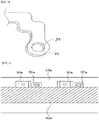
- FIG. 1 is a view illustrating a shape of a first battery terminal connection part formed on a metal plate 10 according to one embodiment of the present invention
- FIG. 2 is a view illustrating shapes of a first battery terminal connection part and a second battery terminal connection part formed on a metal plate according to one embodiment of the present invention.
- the first and second battery terminal connection parts will be respectively described as a first terminal connection part 20 and a second terminal connection part 30.
- a bus bar 1 may include the first terminal connection part 20, the second terminal connection part 30, a fixing part 50, and a terminal main body 60.
- the metal plate 10 may be formed of aluminum and an aluminum alloy or copper and a copper alloy.
- FIG. 1 is a view illustrating a shape of the first terminal connection part 20 primarily formed on the metal plate 10.
- a first press process may be employed to form the first terminal connection part 20.
- An outer shape of the battery terminal connection part including the first terminal connection part 20 may be formed by press processing, and at least one through hole connected to an outer side of a battery may be formed in the first terminal connection part 20.
- a process of making a first through hole 22 passing through the first terminal connection part 20 may also be included in the first press process for manufacturing the outer shape of the first terminal connection part 20.
- a battery electrode may pass through an inner side surface of the first through hole 22 and may be connected to a battery terminal.
- the inner side surface of the first through hole 22 may be plated to minimize variation of contact resistance and reduce resistance of the first through hole 22 serving as an electrical contact part.
- the first terminal connection part 20 may have a circular shape as illustrated in FIG. 1 , but the present invention is not limited thereto and may have an elliptical shape, a polygonal shape, a combined shape formed of curves or straight lines, etc.
- a position of the first terminal connection part 20 is not limited to the example illustrated in FIG. 1 .
- the first press process for the first terminal connection part 20 may include a predetermined area positioned at an outer side thereof.
- a perimeter of the predetermined area may include at least one straight line.
- FIG. 2 is a view illustrating a shape of the second terminal connection part 30 above the first terminal connection part 20 on the metal plate 10.
- the press process may be employed to form an outer shape of the second terminal connection part 30 when performing the first press process.
- An outer shape of a battery terminal connection part including the second terminal connection part 30 may be formed by press processing, and at least one through hole connected to an outer side of a battery may be formed in the second terminal connection part 30.
- a process of making a second through hole 32 may be included in the press process for manufacturing the outer shape of the second terminal connection part 30.
- a battery electrode may pass through an inner side surface of the second through hole 32 and may be connected to a battery terminal.
- the inner side surface of the through hole may be plated to minimize variation of contact resistance and reduce resistance of the second through hole 32 serving as an electrical contact part.
- the second terminal connection part 30 may have a rectangular shape as illustrated in FIG. 2 , but the present invention is not limited thereto and may have an elliptical shape, a polygonal shape, curves or straight lines, a combination of curves and straight lines, etc.
- a position of the second terminal connection part 30 is not limited to an example illustrated in FIG. 2 .
- a predetermined area positioned at an outer side of the second terminal connection part 30 may be included during performing the first press process.
- the perimeter of the predetermined area may include at least one straight line.
- the first terminal connection part 20 and the second terminal connection part 30 which will be connected to a battery terminal may be plated and thermally processed after performing the first press process.
- a masking process may be performed beforehand.
- a mask 40 for plating may be applied onto a remaining area except the first terminal connection part 20, the second terminal connection part 30, and the predetermined areas.
- the mask 40 may also be applied onto the opposite surface of the metal plate 10.
- the masking process, which is performed before performing the plating and the thermal processes, for the plating and the thermal processes may be performed in a method of putting on tape 40a rather than using the mask 40.
- FIG. 6 is a view illustrating a masking process according to another embodiment of the present invention.
- FIG. 6 illustrates a form of putting tape on a remaining area except a battery connection part and a predetermined area.
- a first terminal connection part 20a may be positioned in a direction of one side of a second terminal connection part 30a, and a position of the first terminal connection part 20a may be modified depending on a method of a masking process.
- Tape 40a for plating the first terminal connection part 20a and the second terminal connection part 30a may be put on a remaining area of a metal plate 10a except the first terminal connection part 20a and the second terminal connection part 30a which are formed in one direction.
- the tape 40a may be put on the metal plate 10a in the form of a band because the positions of the first terminal connection part 20a and the second terminal connection part 30a are formed in the same direction.
- the plating may be performed using at least one metal among nickel (Ni), gold (Au), copper (Cu), and tin (Sn).
- the plating may be performed by electroplating, and the mask 40 and the tape 40a applied on the metal plate 10 may be removed after performing the plating.
- FIG. 4 illustrates a shape of the bus bar 1 that is an electrical connector for a battery of an electric vehicle and has shapes of the first terminal connection part 20 and the second terminal connection part 30 in which the plating layers are completed and on which a second press process is performed.
- At least one metal among nickel (Ni), gold (Au), copper (Cu), and tin (Sn) may be used to form the plating layers of the first terminal connection part 20 and the second terminal connection part 30.
- tin plating may be performed after performing nickel plating on the first terminal connection part 20 and the second terminal connection part 30, or the nickel plating may be performed after performing copper plating.
- a cleaning process may be performed to remove the residual plating solution when the plating process is completed.
- a second press process may be used to form an outer shape of the bus bar 1 after performing the plating process, and thereby outer shapes of the terminal main body 60 and the fixing part 50 may be formed.
- a coupling part through hole 52 which may be used to fix a battery of an electric vehicle, may be included in the fixing part 50, and the press process may be performed to make the coupling part through hole 52.
- the first terminal connection part 20 and the second terminal connection part 30 may be connected by the terminal main body 60, and the fixing part 50 and the coupling part through hole 52 may be formed for fixing the bus bar 1 to an outer side of a battery (not shown).
- the terminal main body 60 and the first terminal connection part 20 may be connected using at least one shape of a curve, a straight line, or a combination of a curve and a straight line. As illustrated in FIG. 4 , the terminal main body 60 may have a rectangular shape. However, the present invention is not limited thereto, and the shape of the terminal main body 60 may include a circular or polygonal shape.
- the fixing part 50 for fixing the bus bar 1 to an outer side of a battery may be formed at a lower side of the bus bar 1.
- the terminal main body 60 and the fixing part 50 may be connected using at least one shape of a curve, a straight line, or a combination of a curve and a straight line.
- FIG. 5 is a view in which a through hole plating layer 24 is formed at an inner side surface of the first through hole 22.
- the first through hole 22 may be connected to an outer side of a battery (not shown) via an electrical connection.
- FIG. 7 illustrates a shape of a bus bar 1 according to another embodiment of the present invention.
- FIG. 7A is a view illustrating outer shapes of a first terminal connection part 20b and a second terminal connection part 30b formed by a first press process.
- a press process may be employed to form the outer shapes of the first terminal connection part 20b and the second terminal connection part 30b.
- a mask may be attached to an area except the terminal connection parts for plating and thermally processing the first terminal connection part 20b and the second terminal connection part 30b.
- the plating may be performed using at least one metal among nickel (Ni), gold (Au), copper (Cu), and tin (Sn).
- each of a first terminal 70 and a second terminal 72 may be formed to couple the first terminal connection part 20b and the second terminal connection part 30b.
- a second press process may be performed to form the first terminal 70 and the second terminal 72.
- the first terminal 70 and the second terminal 72 which are respectively connected to the first terminal connection part 20b and the second terminal connection part 30b, may be formed with curves, straight lines, or a combination of straight lines and curves.
- a method of manufacturing the bus bar 1 may be the same as in the embodiment described above.
- a coupling process may be performed to couple the first terminal connection part 20b and the second terminal connection part 30b.
- the first terminal connection part 20b and the second terminal connection part 30b may be coupled by an ultrasonic fusing process.
- the first terminal 70 connected to the first terminal connection part 20b may be mounted on the second terminal 72 connected to second terminal connection part 30b.
- the first terminal 70 may be melted by applying an ultrasonic vibration to the first terminal 70 mounted on the second terminal 72, by which a large amount of heat may be instantaneously generated and the first terminal 70 may thus be fused to the second terminal 72.
- FIG. 7B is a view illustrating a shape in which the first terminal connection part 20b and the second terminal connection part 30b are fused. Positions of the first terminal connection part 20b and the second terminal connection part 30b are not limited to the illustration of FIG.
- Aluminum and an aluminum alloy or copper or a copper alloy may be used as a metal plate of the bus bar 1 manufactured by the ultrasonic fusing process, and the first terminal connection part 20b and the second terminal connection part 30b of dissimilar metals may be fused as well.
- aluminum and an aluminum alloy may be used as the first terminal connection part 20b
- copper and a copper alloy may be used as the second terminal connection part 30b to form the bus bar of dissimilar metals.
- the method of manufacturing the bus bar 1 by the ultrasonic fusing process reduces manufacturing time and maintains continuity of the manufacturing process due to instantaneous fusing of the first terminal 70 and the second terminal 72, thereby enabling mass production. Delays in manufacturing are inevitable in the conventional technologies in which the bus bar 1 is plated after processing the shape of the bus bar 1. In addition, when the shape of the bus bar 1 is processed after the metal plate 10 is plated, the plating layer may not be formed at the inner side surface of the through hole serving as an electrical contact part. Accordingly, a significant amount of manufacturing time is required, and productivity in mass production may be significantly lowered.
- the present invention relates to the bus bar 1 serving as the electrical connector for a battery of an electric vehicle and a method of manufacturing thereof, and the simplified manufacturing process allows minimized manufacturing time and mass production.
- the present invention reduces the problem of a cut off portion of the through hole connected to an outer side of a battery (not shown) not being plated when a metal plate is plated before the press process.
- a method of manufacturing the electrical connector is provided, and the method can reduce processing time of manufacturing the electrical connector by manufacturing the battery terminal connection part at a metal plate in a desired shape and performing a plating process thereon, thereby enabling mass production of the electrical connector.
- a method of manufacturing the electrical connector is provided, and the method can enhance electrical properties in the process of manufacturing the shape of the electrical connector by forming a uniform plating layer also at the inner side surface of the through hole in the battery terminal connection part through which a battery electrode passes.
Description
- The present invention relates to a method of manufacturing an electrical connector.
-
US 2014/099543 A1 discloses a method of manufacturing an electrical connector having a through hole therein comprising the step of removing a through hole part from the metal side, performing masking on an area of the connector, partially plating the connector, and performing a cladding process comprising pressing on the plate. -
WO 2014/024448 A1 discloses a method of manufacturing an electrical connector comprising the steps of making holes in the plates, cladding two parts for producing the connector, masking a part of the connector, and plating partially the connector. - Generally, a bus bar is used for transmission of electricity in an electric vehicle. A bus bar is a conductor having low impedance and a high current capacity, and can individually connect two or more circuits or connect several like points in a system. A bus bar is generally and frequently used as a common conductor which distributes power to several points. Plating is generally performed on a connecting part in such a bus bar to enhance electrical characteristics. In a conventional method of manufacturing a bus bar, a shape of a bus bar is first formed using a press process or the like, and rack plating and cleaning processes are then performed on a connecting terminal of the bus bar to complete the manufacturing. The rack plating process refers to a method of plating a bus bar that is hung on a rack. In this case, the manufacturing process is inconvenient, and continuity of a manufacturing process is hard to achieve because plating is separately performed by hanging the bus bar on a rack after a process of manufacturing the bus bar of a desired shape.
- To resolve the above problem, a method is used for manufacturing a bus bar of a desired shape after plating is performed on a metal plate itself in advance for manufacturing the bus bar. However, in this case, since a connecting part is cut off after being plated and the cut off surface is not plated, electrical properties are degraded because the surface in contact with a battery electrode or the like is not actually plated.
- (Patent Document 1) Patent Laid-Open Publication No.
10-2014-0146232 (2014.12.24 - The present invention is directed to providing a method of manufacturing an electrical connector capable of mass production by minimizing inconvenience of going through multiple processes and reducing manufacturing time of the electrical connector during manufacturing of an electrical connector.
- In addition, the present invention is directed to providing a method of manufacturing an electrical connector in which a uniform plating layer is formed on an inner side surface of a terminal connection part through which a battery electrode passes.
- According to the present invention, there is provided a method of manufacturing an electrical connector as defined in
independent claims 1 and 11, respectively. - The first process may be performed by removing the through hole part and a predetermined part positioned at outer side of the battery terminal connection part.
- The electrical connector may include a bus bar.
- The bus bar may be used in an electric vehicle.
- The at least one battery terminal connection part may be two in number.
- A cut-off surface of the through hole may be connected to an outer side of a terminal of the battery.
- A perimeter of the predetermined area may be formed with straight lines, curves, and a combination of straight lines and curves.
- The masking may be performed using a mask in which the battery connection part and the predetermined part are removed.
- The masking may be performed by putting tape on an area except the battery connection part and the predetermined part.
- The plating may be performed using at least one metal among nickel (Ni), gold (Au), copper (Cu), and tin (Sn).
- The performing of the first process and the second process may include a press process.
- The above and other objects, features and advantages of the present invention will become more apparent to those of ordinary skill in the art by describing in detail exemplary embodiments thereof with reference to the accompanying drawings, in which:
-
FIG. 1 is a view illustrating a shape of a first terminal connection part on a metal plate according to one embodiment of the present invention; -
FIG. 2 is a view illustrating shapes of a first terminal connection part and a second terminal connection part on a metal plate according to one embodiment of the present invention; -
FIG. 3 is a view in which a mask for plating is applied onto a remaining area except a battery connection part and a predetermined area according to one embodiment of the present invention; -
FIG. 4 is a view illustrating a shape of a bus bar according to one embodiment of the present invention; -
FIG. 5 is a view illustrating a terminal connection part of which an inner side surface of a through hole is plated according to one embodiment of the present invention; -
FIG. 6 is a view in which tape is put on a remaining area except a battery connection part and a predetermined area according to one embodiment of the present invention; and -
FIG. 7 is a view illustrating a shape of a bus bar according to another embodiment of the present invention. - Hereinafter, a method of manufacturing an electrical connector will be described in detail according to exemplary embodiments of the present invention with reference to
FIGS. 1 to 5 . However, the embodiments should be considered in a descriptive sense only, and the present invention is not limited to the embodiments set forth herein. - In the description, detailed descriptions of well-known technologies related to the present invention will be omitted where they may unnecessarily obscure the subject matters of the invention. In addition, terms described below are defined considering functions of the present invention, but the terms may be changed by intention or practice of users and operators. Thus, definitions of these terms have to be made on the basis of the content throughout the specification.
- Inventive concept of the present invention shall be determined only according to the technical sprit of the attached claims, and the embodiments below are provided only to efficiently convey the advanced concept of the present invention to those skilled in the art.
- Meanwhile, the directional terms "upper side," "lower side," "one side" and the like are used in relation to directions in the drawings disclosed. Since elements in the embodiments of the present invention may be set in various directions, the directional terms are used in a descriptive sense only and not for the purpose of limitation.
- Although the terms "first," "second," etc. may be used herein to describe various elements, these elements should not be limited by these terms. These terms are only used to distinguish one element from another. For example, a first element could be termed a second element, and, similarly, a second element could be termed a first element, without departing from the scope of exemplary embodiments.
-
FIG. 1 is a view illustrating a shape of a first battery terminal connection part formed on ametal plate 10 according to one embodiment of the present invention, andFIG. 2 is a view illustrating shapes of a first battery terminal connection part and a second battery terminal connection part formed on a metal plate according to one embodiment of the present invention. Hereinafter for convenience, the first and second battery terminal connection parts will be respectively described as a firstterminal connection part 20 and a secondterminal connection part 30. - Referring to
FIG. 2 orFIG. 4 , abus bar 1 may include the firstterminal connection part 20, the secondterminal connection part 30, afixing part 50, and a terminalmain body 60. When manufacturing thebus bar 1, themetal plate 10 may be formed of aluminum and an aluminum alloy or copper and a copper alloy.FIG. 1 is a view illustrating a shape of the firstterminal connection part 20 primarily formed on themetal plate 10. Here, a first press process may be employed to form the firstterminal connection part 20. An outer shape of the battery terminal connection part including the firstterminal connection part 20 may be formed by press processing, and at least one through hole connected to an outer side of a battery may be formed in the firstterminal connection part 20. A process of making a first throughhole 22 passing through the firstterminal connection part 20 may also be included in the first press process for manufacturing the outer shape of the firstterminal connection part 20. A battery electrode may pass through an inner side surface of the first throughhole 22 and may be connected to a battery terminal. The inner side surface of the first throughhole 22 may be plated to minimize variation of contact resistance and reduce resistance of the first throughhole 22 serving as an electrical contact part. The firstterminal connection part 20 may have a circular shape as illustrated inFIG. 1 , but the present invention is not limited thereto and may have an elliptical shape, a polygonal shape, a combined shape formed of curves or straight lines, etc. In addition, a position of the firstterminal connection part 20 is not limited to the example illustrated inFIG. 1 . The first press process for the firstterminal connection part 20 may include a predetermined area positioned at an outer side thereof. A perimeter of the predetermined area may include at least one straight line. By forming the predetermined area, a plating layer for an outer side of the firstterminal connection part 20 or the inner side surface of the first throughhole 22 formed in the firstterminal connection part 20 may easily be formed. -
FIG. 2 is a view illustrating a shape of the secondterminal connection part 30 above the firstterminal connection part 20 on themetal plate 10. Here, the press process may be employed to form an outer shape of the secondterminal connection part 30 when performing the first press process. An outer shape of a battery terminal connection part including the secondterminal connection part 30 may be formed by press processing, and at least one through hole connected to an outer side of a battery may be formed in the secondterminal connection part 30. A process of making a second throughhole 32 may be included in the press process for manufacturing the outer shape of the secondterminal connection part 30. A battery electrode may pass through an inner side surface of the second throughhole 32 and may be connected to a battery terminal. The inner side surface of the through hole may be plated to minimize variation of contact resistance and reduce resistance of the second throughhole 32 serving as an electrical contact part. The secondterminal connection part 30 may have a rectangular shape as illustrated inFIG. 2 , but the present invention is not limited thereto and may have an elliptical shape, a polygonal shape, curves or straight lines, a combination of curves and straight lines, etc. In addition, a position of the secondterminal connection part 30 is not limited to an example illustrated inFIG. 2 . A predetermined area positioned at an outer side of the secondterminal connection part 30 may be included during performing the first press process. The perimeter of the predetermined area may include at least one straight line. By forming the predetermined area, a plating layer for an outer side of the secondterminal connection part 30 and the inner side surface of the second throughhole 32 formed in the secondterminal connection part 30 may easily be formed. - Referring to
FIGS. 3 and6 , the firstterminal connection part 20 and the secondterminal connection part 30 which will be connected to a battery terminal may be plated and thermally processed after performing the first press process. For performing the plating process and the thermal process, a masking process may be performed beforehand. For the masking, amask 40 for plating may be applied onto a remaining area except the firstterminal connection part 20, the secondterminal connection part 30, and the predetermined areas. Themask 40 may also be applied onto the opposite surface of themetal plate 10. The masking process, which is performed before performing the plating and the thermal processes, for the plating and the thermal processes may be performed in a method of putting ontape 40a rather than using themask 40. -
FIG. 6 is a view illustrating a masking process according to another embodiment of the present invention.FIG. 6 illustrates a form of putting tape on a remaining area except a battery connection part and a predetermined area. A firstterminal connection part 20a may be positioned in a direction of one side of a secondterminal connection part 30a, and a position of the firstterminal connection part 20a may be modified depending on a method of a masking process.Tape 40a for plating the firstterminal connection part 20a and the secondterminal connection part 30a may be put on a remaining area of ametal plate 10a except the firstterminal connection part 20a and the secondterminal connection part 30a which are formed in one direction. When the plating is performed using thetape 40a, thetape 40a may be put on themetal plate 10a in the form of a band because the positions of the firstterminal connection part 20a and the secondterminal connection part 30a are formed in the same direction. - The plating may be performed using at least one metal among nickel (Ni), gold (Au), copper (Cu), and tin (Sn). The plating may be performed by electroplating, and the
mask 40 and thetape 40a applied on themetal plate 10 may be removed after performing the plating. -
FIG. 4 illustrates a shape of thebus bar 1 that is an electrical connector for a battery of an electric vehicle and has shapes of the firstterminal connection part 20 and the secondterminal connection part 30 in which the plating layers are completed and on which a second press process is performed. At least one metal among nickel (Ni), gold (Au), copper (Cu), and tin (Sn) may be used to form the plating layers of the firstterminal connection part 20 and the secondterminal connection part 30. For example, tin plating may be performed after performing nickel plating on the firstterminal connection part 20 and the secondterminal connection part 30, or the nickel plating may be performed after performing copper plating. A cleaning process may be performed to remove the residual plating solution when the plating process is completed. A second press process may be used to form an outer shape of thebus bar 1 after performing the plating process, and thereby outer shapes of the terminalmain body 60 and the fixingpart 50 may be formed. A coupling part throughhole 52, which may be used to fix a battery of an electric vehicle, may be included in the fixingpart 50, and the press process may be performed to make the coupling part throughhole 52. By the second press process, the firstterminal connection part 20 and the secondterminal connection part 30 may be connected by the terminalmain body 60, and the fixingpart 50 and the coupling part throughhole 52 may be formed for fixing thebus bar 1 to an outer side of a battery (not shown). The terminalmain body 60 and the firstterminal connection part 20 may be connected using at least one shape of a curve, a straight line, or a combination of a curve and a straight line. As illustrated inFIG. 4 , the terminalmain body 60 may have a rectangular shape. However, the present invention is not limited thereto, and the shape of the terminalmain body 60 may include a circular or polygonal shape. The fixingpart 50 for fixing thebus bar 1 to an outer side of a battery (not shown) may be formed at a lower side of thebus bar 1. The terminalmain body 60 and the fixingpart 50 may be connected using at least one shape of a curve, a straight line, or a combination of a curve and a straight line. -
FIG. 5 is a view in which a throughhole plating layer 24 is formed at an inner side surface of the first throughhole 22. The first throughhole 22 may be connected to an outer side of a battery (not shown) via an electrical connection. -
FIG. 7 illustrates a shape of abus bar 1 according to another embodiment of the present invention.FIG. 7A is a view illustrating outer shapes of a firstterminal connection part 20b and a secondterminal connection part 30b formed by a first press process. A press process may be employed to form the outer shapes of the firstterminal connection part 20b and the secondterminal connection part 30b. After the first press process, a mask may be attached to an area except the terminal connection parts for plating and thermally processing the firstterminal connection part 20b and the secondterminal connection part 30b. The plating may be performed using at least one metal among nickel (Ni), gold (Au), copper (Cu), and tin (Sn). When the plating is completed, each of afirst terminal 70 and a second terminal 72 may be formed to couple the firstterminal connection part 20b and the secondterminal connection part 30b. A second press process may be performed to form thefirst terminal 70 and the second terminal 72. Thefirst terminal 70 and the second terminal 72, which are respectively connected to the firstterminal connection part 20b and the secondterminal connection part 30b, may be formed with curves, straight lines, or a combination of straight lines and curves. A method of manufacturing thebus bar 1 may be the same as in the embodiment described above. When the plating process is completed, according to another embodiment of the present invention, a coupling process may be performed to couple the firstterminal connection part 20b and the secondterminal connection part 30b. For example, the firstterminal connection part 20b and the secondterminal connection part 30b may be coupled by an ultrasonic fusing process. To couple the battery terminal parts, thefirst terminal 70 connected to the firstterminal connection part 20b may be mounted on the second terminal 72 connected to secondterminal connection part 30b. Thefirst terminal 70 may be melted by applying an ultrasonic vibration to thefirst terminal 70 mounted on the second terminal 72, by which a large amount of heat may be instantaneously generated and thefirst terminal 70 may thus be fused to the second terminal 72.FIG. 7B is a view illustrating a shape in which the firstterminal connection part 20b and the secondterminal connection part 30b are fused. Positions of the firstterminal connection part 20b and the secondterminal connection part 30b are not limited to the illustration ofFIG. 7 and may be modified. Aluminum and an aluminum alloy or copper or a copper alloy may be used as a metal plate of thebus bar 1 manufactured by the ultrasonic fusing process, and the firstterminal connection part 20b and the secondterminal connection part 30b of dissimilar metals may be fused as well. For example, aluminum and an aluminum alloy may be used as the firstterminal connection part 20b, and copper and a copper alloy may be used as the secondterminal connection part 30b to form the bus bar of dissimilar metals. - The method of manufacturing the
bus bar 1 by the ultrasonic fusing process reduces manufacturing time and maintains continuity of the manufacturing process due to instantaneous fusing of thefirst terminal 70 and the second terminal 72, thereby enabling mass production. Delays in manufacturing are inevitable in the conventional technologies in which thebus bar 1 is plated after processing the shape of thebus bar 1. In addition, when the shape of thebus bar 1 is processed after themetal plate 10 is plated, the plating layer may not be formed at the inner side surface of the through hole serving as an electrical contact part. Accordingly, a significant amount of manufacturing time is required, and productivity in mass production may be significantly lowered. - The present invention relates to the
bus bar 1 serving as the electrical connector for a battery of an electric vehicle and a method of manufacturing thereof, and the simplified manufacturing process allows minimized manufacturing time and mass production. In addition, the present invention reduces the problem of a cut off portion of the through hole connected to an outer side of a battery (not shown) not being plated when a metal plate is plated before the press process. - According to the embodiments of the present invention, a method of manufacturing the electrical connector is provided, and the method can reduce processing time of manufacturing the electrical connector by manufacturing the battery terminal connection part at a metal plate in a desired shape and performing a plating process thereon, thereby enabling mass production of the electrical connector.
- In addition, according to the embodiments of the present invention, a method of manufacturing the electrical connector is provided, and the method can enhance electrical properties in the process of manufacturing the shape of the electrical connector by forming a uniform plating layer also at the inner side surface of the through hole in the battery terminal connection part through which a battery electrode passes.
- While the present invention has been described in connection with exemplary embodiments, it should be understood to those skilled in the art that various modifications may be made from the embodiments described above. Accordingly, the scope of the present invention is not limited to the embodiments described above, but should be defined according to the attached claims.
-
- 1 : BUS BAR
- 10, 10a : METAL PLATE
- 20 ,
20a 20b: FIRST TERMINAL CONNECTION PART - 22: FIRST THROUGH HOLE
- 24 : PLATING LAYER IN THROUGH HOLE
- 30, 30a, 30b : SECOND TERMINAL CONNECTION PART
- 32: SECOND THROUGH HOLE
- 40: MASK
- 40a : TAPE
- 50 : COUPLING PART
- 52 : COUPLING PART THRIUGH HOLE
- 60 : TERMINAL MAIN BODY
- 70 : FIRST TERMINAL
- 72 : SECOND TERMINAL
Claims (15)
- A method of manufacturing an electrical connector including at least one battery terminal connection part (20, 30) having a through hole (22, 32) therein, the method comprising:performing a first pressing process on a metal plate (10) to form the at least one battery terminal connection part (20, 30) which is a target to be plated;performing masking on an area except the battery terminal connection part(20, 30);performing plating on the battery terminal connection part(20, 30); andperforming a second pressing process to form a remaining part except the at least one battery terminal connection part (20, 30) in the electrical connector,wherein a cut-off surface of the through hole (22, 32) is also plated during the performing of the plating on the battery terminal connection part (20, 30).
- The method of claim 1, wherein the first pressing process is performed by removing the through hole (22, 32) part and a predetermined part positioned at outer side of the battery terminal connection part(20, 30).
- The method of claim 1, wherein the electrical connector includes a bus bar (1).
- The method of claim 3, wherein the bus bar (1) is used in an electric vehicle.
- The method of claim 1, wherein the at least one battery terminal connection part (20, 30) is two in number.
- The method of claim 1, wherein a cut-off surface of the through hole (22, 32) is connected to an outer side of a terminal of the battery.
- The method of claim 2, wherein a perimeter of the predetermined area is formed with straight lines, curves, and a combination of straight lines and curves.
- The method of claim 2, wherein the masking is performed using a mask (40) in which the battery connection part (20, 30) and the predetermined part are removed.
- The method of claim 2, wherein the masking is performed by putting tape (40a) on an area except the battery connection part (20a, 30a) and the predetermined part.
- The method of claim 1, wherein the plating is performed using at least one metal among nickel (Ni), gold (Au), copper (Cu), and tin (Sn).
- A method of manufacturing an electrical connector including a plurality of battery terminal connection parts (20, 30) each having a through hole (22, 32) therein, the method comprising:performing a first pressing process to form each battery terminal connection part (20, 30), which is a target of fusing, on plates different from each other formed of the same metal material or dissimilar metal materials;performing masking on an area except the battery terminal connection part (20, 30) in each metal material plate;performing plating on each battery terminal connection part(20, 30);performing a second pressing process on each metal material plate (10) to form a coupling part (50) at a remaining area except at least one of the battery terminal connection part(20, 30); andfusing the coupling parts (50) to each other and completing the electrical connector,wherein a cut-off surface of the through hole (22, 32) is also plated during the performing of the plating on the battery terminal connection part (20, 30).
- The method of claim 11, wherein the fusing includes ultrasonic fusing or welding.
- The method of claim 11, wherein the plates (10) of metal materials different from each other are formed of the same metal material.
- The method of claim 11, wherein the plates (10) of metal materials different from each other are formed of dissimilar metal materials.
- The method of claim 11, wherein each of the metal material plates (10) different from each other is formed using at least one among aluminum and an aluminum alloy and copper and a copper alloy.
Applications Claiming Priority (1)
| Application Number | Priority Date | Filing Date | Title |
|---|---|---|---|
| KR1020150118195A KR101623717B1 (en) | 2015-08-21 | 2015-08-21 | Method of manufacturing electronical connection means |
Publications (2)
| Publication Number | Publication Date |
|---|---|
| EP3133676A1 EP3133676A1 (en) | 2017-02-22 |
| EP3133676B1 true EP3133676B1 (en) | 2019-08-21 |
Family
ID=56114099
Family Applications (1)
| Application Number | Title | Priority Date | Filing Date |
|---|---|---|---|
| EP16185155.5A Active EP3133676B1 (en) | 2015-08-21 | 2016-08-22 | Method of manufacturing an electrical connector |
Country Status (5)
| Country | Link |
|---|---|
| US (1) | US10573874B2 (en) |
| EP (1) | EP3133676B1 (en) |
| KR (1) | KR101623717B1 (en) |
| CN (1) | CN106469800A (en) |
| HU (1) | HUE046208T2 (en) |
Families Citing this family (6)
| Publication number | Priority date | Publication date | Assignee | Title |
|---|---|---|---|---|
| KR102383415B1 (en) | 2018-03-20 | 2022-04-06 | 삼성에스디아이 주식회사 | Battery pack |
| KR101996444B1 (en) * | 2018-04-25 | 2019-10-01 | 주식회사 유라코퍼레이션 | Busbar assembly |
| KR102239209B1 (en) * | 2018-10-24 | 2021-04-12 | 대산전자(주) | Plating method and plated metal |
| KR102041494B1 (en) * | 2019-01-22 | 2019-11-07 | 에스 티 (주) | Connecting busbar manufacturing method of battery for electric vehicle |
| CN110311083A (en) * | 2019-07-24 | 2019-10-08 | 宁波市叶兴汽车零部件有限公司 | Vehicular battery connector processing technology |
| KR20210121786A (en) * | 2020-03-31 | 2021-10-08 | 주식회사 엘지에너지솔루션 | High Voltage Busbar Having Dissimilar Metals and Manufacturing Method Thereof |
Family Cites Families (14)
| Publication number | Priority date | Publication date | Assignee | Title |
|---|---|---|---|---|
| JPS59126784A (en) | 1982-12-28 | 1984-07-21 | Fujitsu Ltd | Production of connector terminal |
| KR100737973B1 (en) | 2005-11-25 | 2007-07-13 | 주식회사 우주금속 | process method for battery terminal cellular phone |
| US9196890B2 (en) * | 2009-10-05 | 2015-11-24 | Samsung Sdi Co., Ltd. | Battery module with welded portion between terminals |
| KR101822229B1 (en) | 2010-03-29 | 2018-01-25 | 가부시키가이샤 고베 세이코쇼 | Bus bar and method for producing bus bar |
| JP5715766B2 (en) * | 2010-04-22 | 2015-05-13 | 矢崎総業株式会社 | Wiring material connection structure |
| JP5138118B2 (en) | 2010-12-08 | 2013-02-06 | 古河電気工業株式会社 | Crimp terminal, connection structure, and manufacturing method thereof |
| JP5657418B2 (en) * | 2011-02-16 | 2015-01-21 | 株式会社Uacj | In-vehicle bus bar and manufacturing method thereof |
| KR101915825B1 (en) * | 2011-06-02 | 2018-11-06 | 히타치 긴조쿠 가부시키가이샤 | Negative electrode terminal for battery and method for producing negative electrode terminal for battery |
| US9318734B2 (en) | 2012-05-21 | 2016-04-19 | Tyco Electronics Corporation | Bimetal buss bar assembly |
| JP2015187909A (en) * | 2012-08-09 | 2015-10-29 | 三洋電機株式会社 | Battery pack and electric vehicle including the same and power storage device |
| JP2015187910A (en) * | 2012-08-09 | 2015-10-29 | 三洋電機株式会社 | Battery pack and electric vehicle including the same and power storage device |
| JP6257889B2 (en) * | 2012-10-23 | 2018-01-10 | 日本メクトロン株式会社 | Flexible printed wiring board with bus bar, manufacturing method thereof, and battery system |
| US20140134471A1 (en) * | 2012-11-14 | 2014-05-15 | General Electric Company | Electrical interconnect and method of assembling a rechargeable battery |
| JP2014143159A (en) | 2012-12-28 | 2014-08-07 | Hitachi Metals Ltd | Method of manufacturing electrode terminal connector |
-
2015
- 2015-08-21 KR KR1020150118195A patent/KR101623717B1/en active IP Right Grant
-
2016
- 2016-08-19 CN CN201610694502.8A patent/CN106469800A/en active Pending
- 2016-08-22 US US15/242,710 patent/US10573874B2/en active Active
- 2016-08-22 EP EP16185155.5A patent/EP3133676B1/en active Active
- 2016-08-22 HU HUE16185155A patent/HUE046208T2/en unknown
Non-Patent Citations (1)
| Title |
|---|
| None * |
Also Published As
| Publication number | Publication date |
|---|---|
| CN106469800A (en) | 2017-03-01 |
| US20170054132A1 (en) | 2017-02-23 |
| EP3133676A1 (en) | 2017-02-22 |
| US10573874B2 (en) | 2020-02-25 |
| KR101623717B1 (en) | 2016-05-24 |
| HUE046208T2 (en) | 2020-02-28 |
Similar Documents
| Publication | Publication Date | Title |
|---|---|---|
| EP3133676B1 (en) | Method of manufacturing an electrical connector | |
| US10395793B2 (en) | Conductive member, terminal-equipped conductive member, and method of manufacturing conductive member | |
| US20150111442A1 (en) | Terminal-provided wire, method for manufacturing same and jig | |
| TWI383553B (en) | Connection structure and connection method of coaxial cable harness | |
| CN105210237B (en) | Terminal, the manufacture method with terminal wires and with terminal wires | |
| CN108352215B (en) | Conductive member and method for manufacturing conductive member | |
| EP3029773B1 (en) | Litz wire terminal assembly | |
| WO2015111509A1 (en) | Terminal fitting-equipped electrical wire and method for manufacturing same | |
| WO2014077144A1 (en) | Terminal fitting-equipped electrical wire | |
| CN107004819A (en) | Connecting element, collector-shoe gear and corresponding manufacture method | |
| JP6062593B1 (en) | Manufacturing method of flat braided wire conductor | |
| JP2013131434A (en) | Flexible conductor and flexible conductor manufacturing method | |
| US2799840A (en) | Terminal construction | |
| US11909152B2 (en) | Electrical device with terminal region and method for producing a terminal region | |
| CN108630342A (en) | A kind of soft busbar and preparation method thereof | |
| KR102328685B1 (en) | Cooling plate producing method for battery stack of electric vehicle and cooling plate by the same | |
| KR20060086970A (en) | Circuit board | |
| JP2016100062A (en) | Covered electric wire and method for manufacturing covered electric wire with terminal | |
| EP3841841B1 (en) | Fabric-contact device, system, in particular heating system for a motor vehicle, and method for producing such a system | |
| CN101192487A (en) | Fuse manufacture method | |
| JP2004511888A (en) | How to connect a flat laminate cable | |
| WO2017082140A1 (en) | Method for producing terminal-equipped conductive member, and conductive member | |
| CN104953219A (en) | RF board end connector and manufacturing method thereof | |
| KR100658809B1 (en) | Method of producing fuses | |
| CN209930634U (en) | Efficient soft board target punching electroplating lead device |
Legal Events
| Date | Code | Title | Description |
|---|---|---|---|
| PUAI | Public reference made under article 153(3) epc to a published international application that has entered the european phase |
Free format text: ORIGINAL CODE: 0009012 |
|
| STAA | Information on the status of an ep patent application or granted ep patent |
Free format text: STATUS: THE APPLICATION HAS BEEN PUBLISHED |
|
| AK | Designated contracting states |
Kind code of ref document: A1 Designated state(s): AL AT BE BG CH CY CZ DE DK EE ES FI FR GB GR HR HU IE IS IT LI LT LU LV MC MK MT NL NO PL PT RO RS SE SI SK SM TR |
|
| AX | Request for extension of the european patent |
Extension state: BA ME |
|
| STAA | Information on the status of an ep patent application or granted ep patent |
Free format text: STATUS: REQUEST FOR EXAMINATION WAS MADE |
|
| 17P | Request for examination filed |
Effective date: 20170822 |
|
| RBV | Designated contracting states (corrected) |
Designated state(s): AL AT BE BG CH CY CZ DE DK EE ES FI FR GB GR HR HU IE IS IT LI LT LU LV MC MK MT NL NO PL PT RO RS SE SI SK SM TR |
|
| GRAP | Despatch of communication of intention to grant a patent |
Free format text: ORIGINAL CODE: EPIDOSNIGR1 |
|
| STAA | Information on the status of an ep patent application or granted ep patent |
Free format text: STATUS: GRANT OF PATENT IS INTENDED |
|
| RIC1 | Information provided on ipc code assigned before grant |
Ipc: H01M 2/20 20060101ALI20190128BHEP Ipc: C25D 5/02 20060101ALI20190128BHEP Ipc: C25D 7/00 20060101ALI20190128BHEP Ipc: H01M 2/30 20060101AFI20190128BHEP |
|
| INTG | Intention to grant announced |
Effective date: 20190305 |
|
| GRAS | Grant fee paid |
Free format text: ORIGINAL CODE: EPIDOSNIGR3 |
|
| GRAA | (expected) grant |
Free format text: ORIGINAL CODE: 0009210 |
|
| STAA | Information on the status of an ep patent application or granted ep patent |
Free format text: STATUS: THE PATENT HAS BEEN GRANTED |
|
| AK | Designated contracting states |
Kind code of ref document: B1 Designated state(s): AL AT BE BG CH CY CZ DE DK EE ES FI FR GB GR HR HU IE IS IT LI LT LU LV MC MK MT NL NO PL PT RO RS SE SI SK SM TR |
|
| REG | Reference to a national code |
Ref country code: GB Ref legal event code: FG4D |
|
| REG | Reference to a national code |
Ref country code: CH Ref legal event code: EP |
|
| REG | Reference to a national code |
Ref country code: DE Ref legal event code: R096 Ref document number: 602016018876 Country of ref document: DE |
|
| REG | Reference to a national code |
Ref country code: AT Ref legal event code: REF Ref document number: 1170765 Country of ref document: AT Kind code of ref document: T Effective date: 20190915 |
|
| REG | Reference to a national code |
Ref country code: IE Ref legal event code: FG4D |
|
| REG | Reference to a national code |
Ref country code: LT Ref legal event code: MG4D |
|
| REG | Reference to a national code |
Ref country code: NL Ref legal event code: MP Effective date: 20190821 |
|
| PG25 | Lapsed in a contracting state [announced via postgrant information from national office to epo] |
Ref country code: HR Free format text: LAPSE BECAUSE OF FAILURE TO SUBMIT A TRANSLATION OF THE DESCRIPTION OR TO PAY THE FEE WITHIN THE PRESCRIBED TIME-LIMIT Effective date: 20190821 Ref country code: LT Free format text: LAPSE BECAUSE OF FAILURE TO SUBMIT A TRANSLATION OF THE DESCRIPTION OR TO PAY THE FEE WITHIN THE PRESCRIBED TIME-LIMIT Effective date: 20190821 Ref country code: NO Free format text: LAPSE BECAUSE OF FAILURE TO SUBMIT A TRANSLATION OF THE DESCRIPTION OR TO PAY THE FEE WITHIN THE PRESCRIBED TIME-LIMIT Effective date: 20191121 Ref country code: FI Free format text: LAPSE BECAUSE OF FAILURE TO SUBMIT A TRANSLATION OF THE DESCRIPTION OR TO PAY THE FEE WITHIN THE PRESCRIBED TIME-LIMIT Effective date: 20190821 Ref country code: SE Free format text: LAPSE BECAUSE OF FAILURE TO SUBMIT A TRANSLATION OF THE DESCRIPTION OR TO PAY THE FEE WITHIN THE PRESCRIBED TIME-LIMIT Effective date: 20190821 Ref country code: PT Free format text: LAPSE BECAUSE OF FAILURE TO SUBMIT A TRANSLATION OF THE DESCRIPTION OR TO PAY THE FEE WITHIN THE PRESCRIBED TIME-LIMIT Effective date: 20191223 Ref country code: NL Free format text: LAPSE BECAUSE OF FAILURE TO SUBMIT A TRANSLATION OF THE DESCRIPTION OR TO PAY THE FEE WITHIN THE PRESCRIBED TIME-LIMIT Effective date: 20190821 Ref country code: BG Free format text: LAPSE BECAUSE OF FAILURE TO SUBMIT A TRANSLATION OF THE DESCRIPTION OR TO PAY THE FEE WITHIN THE PRESCRIBED TIME-LIMIT Effective date: 20191121 |
|
| PG25 | Lapsed in a contracting state [announced via postgrant information from national office to epo] |
Ref country code: RS Free format text: LAPSE BECAUSE OF FAILURE TO SUBMIT A TRANSLATION OF THE DESCRIPTION OR TO PAY THE FEE WITHIN THE PRESCRIBED TIME-LIMIT Effective date: 20190821 Ref country code: LV Free format text: LAPSE BECAUSE OF FAILURE TO SUBMIT A TRANSLATION OF THE DESCRIPTION OR TO PAY THE FEE WITHIN THE PRESCRIBED TIME-LIMIT Effective date: 20190821 Ref country code: GR Free format text: LAPSE BECAUSE OF FAILURE TO SUBMIT A TRANSLATION OF THE DESCRIPTION OR TO PAY THE FEE WITHIN THE PRESCRIBED TIME-LIMIT Effective date: 20191122 Ref country code: ES Free format text: LAPSE BECAUSE OF FAILURE TO SUBMIT A TRANSLATION OF THE DESCRIPTION OR TO PAY THE FEE WITHIN THE PRESCRIBED TIME-LIMIT Effective date: 20190821 Ref country code: AL Free format text: LAPSE BECAUSE OF FAILURE TO SUBMIT A TRANSLATION OF THE DESCRIPTION OR TO PAY THE FEE WITHIN THE PRESCRIBED TIME-LIMIT Effective date: 20190821 Ref country code: IS Free format text: LAPSE BECAUSE OF FAILURE TO SUBMIT A TRANSLATION OF THE DESCRIPTION OR TO PAY THE FEE WITHIN THE PRESCRIBED TIME-LIMIT Effective date: 20191221 |
|
| REG | Reference to a national code |
Ref country code: HU Ref legal event code: AG4A Ref document number: E046208 Country of ref document: HU |
|
| PG25 | Lapsed in a contracting state [announced via postgrant information from national office to epo] |
Ref country code: TR Free format text: LAPSE BECAUSE OF FAILURE TO SUBMIT A TRANSLATION OF THE DESCRIPTION OR TO PAY THE FEE WITHIN THE PRESCRIBED TIME-LIMIT Effective date: 20190821 |
|
| PG25 | Lapsed in a contracting state [announced via postgrant information from national office to epo] |
Ref country code: PL Free format text: LAPSE BECAUSE OF FAILURE TO SUBMIT A TRANSLATION OF THE DESCRIPTION OR TO PAY THE FEE WITHIN THE PRESCRIBED TIME-LIMIT Effective date: 20190821 Ref country code: RO Free format text: LAPSE BECAUSE OF FAILURE TO SUBMIT A TRANSLATION OF THE DESCRIPTION OR TO PAY THE FEE WITHIN THE PRESCRIBED TIME-LIMIT Effective date: 20190821 Ref country code: IT Free format text: LAPSE BECAUSE OF FAILURE TO SUBMIT A TRANSLATION OF THE DESCRIPTION OR TO PAY THE FEE WITHIN THE PRESCRIBED TIME-LIMIT Effective date: 20190821 Ref country code: EE Free format text: LAPSE BECAUSE OF FAILURE TO SUBMIT A TRANSLATION OF THE DESCRIPTION OR TO PAY THE FEE WITHIN THE PRESCRIBED TIME-LIMIT Effective date: 20190821 Ref country code: DK Free format text: LAPSE BECAUSE OF FAILURE TO SUBMIT A TRANSLATION OF THE DESCRIPTION OR TO PAY THE FEE WITHIN THE PRESCRIBED TIME-LIMIT Effective date: 20190821 |
|
| PG25 | Lapsed in a contracting state [announced via postgrant information from national office to epo] |
Ref country code: CH Free format text: LAPSE BECAUSE OF NON-PAYMENT OF DUE FEES Effective date: 20190831 Ref country code: LU Free format text: LAPSE BECAUSE OF NON-PAYMENT OF DUE FEES Effective date: 20190822 Ref country code: SM Free format text: LAPSE BECAUSE OF FAILURE TO SUBMIT A TRANSLATION OF THE DESCRIPTION OR TO PAY THE FEE WITHIN THE PRESCRIBED TIME-LIMIT Effective date: 20190821 Ref country code: CZ Free format text: LAPSE BECAUSE OF FAILURE TO SUBMIT A TRANSLATION OF THE DESCRIPTION OR TO PAY THE FEE WITHIN THE PRESCRIBED TIME-LIMIT Effective date: 20190821 Ref country code: MC Free format text: LAPSE BECAUSE OF FAILURE TO SUBMIT A TRANSLATION OF THE DESCRIPTION OR TO PAY THE FEE WITHIN THE PRESCRIBED TIME-LIMIT Effective date: 20190821 Ref country code: IS Free format text: LAPSE BECAUSE OF FAILURE TO SUBMIT A TRANSLATION OF THE DESCRIPTION OR TO PAY THE FEE WITHIN THE PRESCRIBED TIME-LIMIT Effective date: 20200224 Ref country code: LI Free format text: LAPSE BECAUSE OF NON-PAYMENT OF DUE FEES Effective date: 20190831 Ref country code: SK Free format text: LAPSE BECAUSE OF FAILURE TO SUBMIT A TRANSLATION OF THE DESCRIPTION OR TO PAY THE FEE WITHIN THE PRESCRIBED TIME-LIMIT Effective date: 20190821 |
|
| REG | Reference to a national code |
Ref country code: BE Ref legal event code: MM Effective date: 20190831 |
|
| REG | Reference to a national code |
Ref country code: DE Ref legal event code: R097 Ref document number: 602016018876 Country of ref document: DE |
|
| PLBE | No opposition filed within time limit |
Free format text: ORIGINAL CODE: 0009261 |
|
| STAA | Information on the status of an ep patent application or granted ep patent |
Free format text: STATUS: NO OPPOSITION FILED WITHIN TIME LIMIT |
|
| PG2D | Information on lapse in contracting state deleted |
Ref country code: IS |
|
| PG25 | Lapsed in a contracting state [announced via postgrant information from national office to epo] |
Ref country code: IE Free format text: LAPSE BECAUSE OF NON-PAYMENT OF DUE FEES Effective date: 20190822 |
|
| 26N | No opposition filed |
Effective date: 20200603 |
|
| PG25 | Lapsed in a contracting state [announced via postgrant information from national office to epo] |
Ref country code: BE Free format text: LAPSE BECAUSE OF NON-PAYMENT OF DUE FEES Effective date: 20190831 Ref country code: SI Free format text: LAPSE BECAUSE OF FAILURE TO SUBMIT A TRANSLATION OF THE DESCRIPTION OR TO PAY THE FEE WITHIN THE PRESCRIBED TIME-LIMIT Effective date: 20190821 |
|
| REG | Reference to a national code |
Ref country code: DE Ref legal event code: R079 Ref document number: 602016018876 Country of ref document: DE Free format text: PREVIOUS MAIN CLASS: H01M0002300000 Ipc: H01M0050543000 |
|
| PG25 | Lapsed in a contracting state [announced via postgrant information from national office to epo] |
Ref country code: CY Free format text: LAPSE BECAUSE OF FAILURE TO SUBMIT A TRANSLATION OF THE DESCRIPTION OR TO PAY THE FEE WITHIN THE PRESCRIBED TIME-LIMIT Effective date: 20190821 |
|
| PG25 | Lapsed in a contracting state [announced via postgrant information from national office to epo] |
Ref country code: MT Free format text: LAPSE BECAUSE OF FAILURE TO SUBMIT A TRANSLATION OF THE DESCRIPTION OR TO PAY THE FEE WITHIN THE PRESCRIBED TIME-LIMIT Effective date: 20190821 |
|
| PG25 | Lapsed in a contracting state [announced via postgrant information from national office to epo] |
Ref country code: MK Free format text: LAPSE BECAUSE OF FAILURE TO SUBMIT A TRANSLATION OF THE DESCRIPTION OR TO PAY THE FEE WITHIN THE PRESCRIBED TIME-LIMIT Effective date: 20190821 |
|
| REG | Reference to a national code |
Ref country code: AT Ref legal event code: UEP Ref document number: 1170765 Country of ref document: AT Kind code of ref document: T Effective date: 20190821 |
|
| PGFP | Annual fee paid to national office [announced via postgrant information from national office to epo] |
Ref country code: GB Payment date: 20230822 Year of fee payment: 8 Ref country code: AT Payment date: 20230822 Year of fee payment: 8 |
|
| PGFP | Annual fee paid to national office [announced via postgrant information from national office to epo] |
Ref country code: HU Payment date: 20230823 Year of fee payment: 8 Ref country code: FR Payment date: 20230825 Year of fee payment: 8 Ref country code: DE Payment date: 20230831 Year of fee payment: 8 |