EP3133640A1 - Non-contact power supply device, and processing apparatus including non-contact power supply device - Google Patents
Non-contact power supply device, and processing apparatus including non-contact power supply device Download PDFInfo
- Publication number
- EP3133640A1 EP3133640A1 EP16184477.4A EP16184477A EP3133640A1 EP 3133640 A1 EP3133640 A1 EP 3133640A1 EP 16184477 A EP16184477 A EP 16184477A EP 3133640 A1 EP3133640 A1 EP 3133640A1
- Authority
- EP
- European Patent Office
- Prior art keywords
- power supply
- feed
- feed line
- closed container
- supply device
- Prior art date
- Legal status (The legal status is an assumption and is not a legal conclusion. Google has not performed a legal analysis and makes no representation as to the accuracy of the status listed.)
- Granted
Links
Images


Classifications
-
- H—ELECTRICITY
- H02—GENERATION; CONVERSION OR DISTRIBUTION OF ELECTRIC POWER
- H02J—CIRCUIT ARRANGEMENTS OR SYSTEMS FOR SUPPLYING OR DISTRIBUTING ELECTRIC POWER; SYSTEMS FOR STORING ELECTRIC ENERGY
- H02J50/00—Circuit arrangements or systems for wireless supply or distribution of electric power
- H02J50/005—Mechanical details of housing or structure aiming to accommodate the power transfer means, e.g. mechanical integration of coils, antennas or transducers into emitting or receiving devices
-
- H—ELECTRICITY
- H02—GENERATION; CONVERSION OR DISTRIBUTION OF ELECTRIC POWER
- H02J—CIRCUIT ARRANGEMENTS OR SYSTEMS FOR SUPPLYING OR DISTRIBUTING ELECTRIC POWER; SYSTEMS FOR STORING ELECTRIC ENERGY
- H02J50/00—Circuit arrangements or systems for wireless supply or distribution of electric power
- H02J50/10—Circuit arrangements or systems for wireless supply or distribution of electric power using inductive coupling
-
- B—PERFORMING OPERATIONS; TRANSPORTING
- B65—CONVEYING; PACKING; STORING; HANDLING THIN OR FILAMENTARY MATERIAL
- B65G—TRANSPORT OR STORAGE DEVICES, e.g. CONVEYORS FOR LOADING OR TIPPING, SHOP CONVEYOR SYSTEMS OR PNEUMATIC TUBE CONVEYORS
- B65G49/00—Conveying systems characterised by their application for specified purposes not otherwise provided for
- B65G49/05—Conveying systems characterised by their application for specified purposes not otherwise provided for for fragile or damageable materials or articles
- B65G49/06—Conveying systems characterised by their application for specified purposes not otherwise provided for for fragile or damageable materials or articles for fragile sheets, e.g. glass
- B65G49/061—Lifting, gripping, or carrying means, for one or more sheets forming independent means of transport, e.g. suction cups, transport frames
-
- B—PERFORMING OPERATIONS; TRANSPORTING
- B65—CONVEYING; PACKING; STORING; HANDLING THIN OR FILAMENTARY MATERIAL
- B65G—TRANSPORT OR STORAGE DEVICES, e.g. CONVEYORS FOR LOADING OR TIPPING, SHOP CONVEYOR SYSTEMS OR PNEUMATIC TUBE CONVEYORS
- B65G49/00—Conveying systems characterised by their application for specified purposes not otherwise provided for
- B65G49/05—Conveying systems characterised by their application for specified purposes not otherwise provided for for fragile or damageable materials or articles
- B65G49/06—Conveying systems characterised by their application for specified purposes not otherwise provided for for fragile or damageable materials or articles for fragile sheets, e.g. glass
- B65G49/063—Transporting devices for sheet glass
- B65G49/064—Transporting devices for sheet glass in a horizontal position
-
- B—PERFORMING OPERATIONS; TRANSPORTING
- B65—CONVEYING; PACKING; STORING; HANDLING THIN OR FILAMENTARY MATERIAL
- B65G—TRANSPORT OR STORAGE DEVICES, e.g. CONVEYORS FOR LOADING OR TIPPING, SHOP CONVEYOR SYSTEMS OR PNEUMATIC TUBE CONVEYORS
- B65G54/00—Non-mechanical conveyors not otherwise provided for
- B65G54/02—Non-mechanical conveyors not otherwise provided for electrostatic, electric, or magnetic
-
- H—ELECTRICITY
- H01—ELECTRIC ELEMENTS
- H01L—SEMICONDUCTOR DEVICES NOT COVERED BY CLASS H10
- H01L21/00—Processes or apparatus adapted for the manufacture or treatment of semiconductor or solid state devices or of parts thereof
- H01L21/67—Apparatus specially adapted for handling semiconductor or electric solid state devices during manufacture or treatment thereof; Apparatus specially adapted for handling wafers during manufacture or treatment of semiconductor or electric solid state devices or components ; Apparatus not specifically provided for elsewhere
- H01L21/673—Apparatus specially adapted for handling semiconductor or electric solid state devices during manufacture or treatment thereof; Apparatus specially adapted for handling wafers during manufacture or treatment of semiconductor or electric solid state devices or components ; Apparatus not specifically provided for elsewhere using specially adapted carriers or holders; Fixing the workpieces on such carriers or holders
- H01L21/6735—Closed carriers
-
- H—ELECTRICITY
- H01—ELECTRIC ELEMENTS
- H01L—SEMICONDUCTOR DEVICES NOT COVERED BY CLASS H10
- H01L21/00—Processes or apparatus adapted for the manufacture or treatment of semiconductor or solid state devices or of parts thereof
- H01L21/67—Apparatus specially adapted for handling semiconductor or electric solid state devices during manufacture or treatment thereof; Apparatus specially adapted for handling wafers during manufacture or treatment of semiconductor or electric solid state devices or components ; Apparatus not specifically provided for elsewhere
- H01L21/677—Apparatus specially adapted for handling semiconductor or electric solid state devices during manufacture or treatment thereof; Apparatus specially adapted for handling wafers during manufacture or treatment of semiconductor or electric solid state devices or components ; Apparatus not specifically provided for elsewhere for conveying, e.g. between different workstations
-
- H—ELECTRICITY
- H01—ELECTRIC ELEMENTS
- H01L—SEMICONDUCTOR DEVICES NOT COVERED BY CLASS H10
- H01L21/00—Processes or apparatus adapted for the manufacture or treatment of semiconductor or solid state devices or of parts thereof
- H01L21/67—Apparatus specially adapted for handling semiconductor or electric solid state devices during manufacture or treatment thereof; Apparatus specially adapted for handling wafers during manufacture or treatment of semiconductor or electric solid state devices or components ; Apparatus not specifically provided for elsewhere
- H01L21/683—Apparatus specially adapted for handling semiconductor or electric solid state devices during manufacture or treatment thereof; Apparatus specially adapted for handling wafers during manufacture or treatment of semiconductor or electric solid state devices or components ; Apparatus not specifically provided for elsewhere for supporting or gripping
- H01L21/6838—Apparatus specially adapted for handling semiconductor or electric solid state devices during manufacture or treatment thereof; Apparatus specially adapted for handling wafers during manufacture or treatment of semiconductor or electric solid state devices or components ; Apparatus not specifically provided for elsewhere for supporting or gripping with gripping and holding devices using a vacuum; Bernoulli devices
-
- H—ELECTRICITY
- H05—ELECTRIC TECHNIQUES NOT OTHERWISE PROVIDED FOR
- H05K—PRINTED CIRCUITS; CASINGS OR CONSTRUCTIONAL DETAILS OF ELECTRIC APPARATUS; MANUFACTURE OF ASSEMBLAGES OF ELECTRICAL COMPONENTS
- H05K7/00—Constructional details common to different types of electric apparatus
- H05K7/20—Modifications to facilitate cooling, ventilating, or heating
- H05K7/2039—Modifications to facilitate cooling, ventilating, or heating characterised by the heat transfer by conduction from the heat generating element to a dissipating body
-
- B—PERFORMING OPERATIONS; TRANSPORTING
- B65—CONVEYING; PACKING; STORING; HANDLING THIN OR FILAMENTARY MATERIAL
- B65G—TRANSPORT OR STORAGE DEVICES, e.g. CONVEYORS FOR LOADING OR TIPPING, SHOP CONVEYOR SYSTEMS OR PNEUMATIC TUBE CONVEYORS
- B65G2201/00—Indexing codes relating to handling devices, e.g. conveyors, characterised by the type of product or load being conveyed or handled
- B65G2201/02—Articles
- B65G2201/0214—Articles of special size, shape or weigh
- B65G2201/022—Flat
-
- B—PERFORMING OPERATIONS; TRANSPORTING
- B65—CONVEYING; PACKING; STORING; HANDLING THIN OR FILAMENTARY MATERIAL
- B65G—TRANSPORT OR STORAGE DEVICES, e.g. CONVEYORS FOR LOADING OR TIPPING, SHOP CONVEYOR SYSTEMS OR PNEUMATIC TUBE CONVEYORS
- B65G2812/00—Indexing codes relating to the kind or type of conveyors
- B65G2812/99—Conveyor systems not otherwise provided for
Definitions
- the present invention relates to a non-contact power supply device, and to a processing apparatus that includes the non-contact power supply device and that is configured to convey an object to be processed such as a semiconductor wafer substrate and a glass substrate inside a closed container, and perform other processes.
- a processing apparatus including a movable body that is made movable by driving a linear motor has been conventionally proposed.
- a processing apparatus including a feed line arranged on a holder, a power supply transformer arranged to be opposed to the feed line directly thereabove, and a movable body placed on the power supply transformer via a member such as a base, for example, has been proposed. That is, the feed line and the power supply transformer in the processing apparatus are configured to be opposed to each other in a non-contact manner in the atmosphere.
- the object to be processed such as a semiconductor wafer substrate and a glass substrate is preferably processed under vacuum at a pressure lower than the atmospheric pressure. Therefore, the movable body is possibly housed in the closed container.
- a processing apparatus configured to house a movable body in a closed container
- a processing apparatus disclosed in JP 5470770 B for example, has been proposed.
- a primary feed line is arranged outside the closed container capable of maintaining the vacuum state.
- a power supply transformer configured to be supplied with power from the primary feed line in a non-contact manner and a movable body configured to move with the movement of the power supply transformer are arranged inside the closed container. That is, the power supply transformer is arranged along the primary feed line inside the closed container via a partition wall of the closed container.
- a high-frequency current is allowed to flow through the primary feed line, and the number of magnetic flux is temporally changed, thereby allowing the primary feed line to be magnetically coupled to a secondary winding of the power supply transformer via the power supply transformer.
- a voltage is induced in the secondary winding of the power supply transformer, and electric power is supplied from the primary feed line to the secondary winding.
- the secondary winding is formed as a resonance circuit, the reactive power is reduced, and the power transmission efficiency is increased.
- the magnetic coupling between the primary feed line and the secondary winding depends on the distance of the space present therebetween. Therefore, in the case where power is supplied to the secondary winding from the primary feed line via the partition wall, as in the processing apparatus of the above-described literature, the distance of the space present between the primary feed line and the secondary winding increases due to the presence of the partition wall. With the increase of the distance of the space, the power transmission efficiency from the primary feed line to the secondary winding decreases, which is a problem.
- heat-conduction, convection, and radiation are generally known.
- the closed container which is a closed space
- none of the heat dissipation methods may not be effective.
- heat dissipation by heat-conduction or convection is impossible, and even radiation is not an effective heat dissipation method.
- heat generated in the primary feed line and the secondary winding as a loss remains inside the closed container.
- Such a problem occurs not only in the case of a processing apparatus in which the inside of the closed container is under vacuum, but also in the case of a processing apparatus in which the inside of the closed container is under atmospheric pressure in the same manner.
- the present invention is a non-contact power supply device that is used in a processing apparatus including a closed container and a moving unit provided inside the closed container so as to be movable inside the closed container, and that is capable of supplying electric power to the moving unit from outside the closed container
- the non-contact power supply device including: a feed unit; and a heat dissipator, wherein the feed unit includes a feed line and a power supply transformer, the feed line includes a feed region arranged inside the closed container along the moving direction of the moving unit, the power supply transformer is arranged inside the closed container so as to be opposed to the feed region in a non-contact manner and is provided to move together with the moving unit, and the heat dissipator includes a portion on one end side connected to the feed region so as to be capable of conducting heat thereto and a portion on the other end side extending outside the closed container.
- the non-contact power supply device of the present invention a configuration in which the portion on one end side of the heat dissipator is electrically connected to the feed region, and electric power is supplied from the portion on the other end side of the heat dissipator to the feed region can be employed.
- the non-contact power supply device of the present invention a configuration in which the non-contact power supply device further includes a plurality of connecting parts configured to connect the portion on one end side of the heat dissipator to the feed region of the feed line, wherein the plurality of connecting parts are arranged along a longitudinal direction of the feed region, so that an equal number of connecting parts are present at a position where the power supply transformer is present, regardless of the position of the power supply transformer, can be employed.
- the closed container is capable of maintaining its internal pressure lower than the atmospheric pressure.
- a processing apparatus of the present invention includes: a closed container; a moving unit provided inside the closed container so as to be movable inside the closed container; and the aforementioned non-contact power supply device.
- a non-contact power supply device when used in a vacuum processing apparatus that is used with the inside of the closed container maintained at a pressure lower than the atmospheric pressure will be described as an example.
- This vacuum processing apparatus is used for conveying an object to be processed such as a semiconductor wafer substrate or a glass substrate or performing other processes.
- a vacuum processing apparatus 1 in the first embodiment includes a closed container (referred to also as vacuum container) 2, a moving unit 3, and a non-contact power supply device 4.
- a closed container referred to also as vacuum container
- a moving unit 3 a moving unit 3
- a non-contact power supply device 4 a non-contact power supply device 4.
- the closed container 2 is formed into a rectangular parallelepiped shape as a whole and is defined by an outer wall 20 between the inner and outer sides of the closed container 2.
- the inside of the closed container 2 is formed as a vacuum chamber 22.
- a pair of rails are installed parallel to each other on both sides of a bottom wall 21 of the closed container 2 (not shown).
- the moving unit 3 includes a movable body 8 in the form of a box that is guided to move along the pair of rails, a power supply transformer 14 configured to be movable with the movement of the movable body 8, and a drive unit (load) 10 that is constituted by a motor or the like and is arranged inside the movable body 8.
- the moving path of the movable body 8 is a path extending in a direction along the longitudinal direction of the closed container 2.
- the non-contact power supply device 4 includes a high frequency power supply 12, feed lines 13, the power supply transformer 14, and heat dissipators 15.
- the high frequency power supply 12 is arranged outside the closed container 2 and is connected to a commercial power supply 16. Since the feed lines 13 are primary feed lines, the feed lines 13 are hereinafter referred to as primary feed lines 13.
- the primary feed lines 13 include two feed line parts of a first feed line part 131 and a second feed line part 132 as forward and return paths.
- the first feed line part 131 and the second feed line part 132 are made of electrically conductive materials (for example, aluminum) so as to have a circular cross section, though not shown in the figures.
- the first feed line part 131 and the second feed line part 132 respectively have linear feed regions 131A and 132A.
- the middle portions in the longitudinal direction of the feed regions 131A and 132A are arranged inside the closed container 2.
- the positions of the feed regions 131A and 132A are maintained so that the feed regions 131A and 132A are spaced apart from the bottom wall 21 at a certain height.
- the feed regions 131A and 132A are arranged parallel to each other at an interval within a horizontal plane including the longitudinal direction of the closed container 2.
- the first feed line part 131 and the second feed line part 132 are arranged along the above-described pair of rails and between the pair of rails.
- the portions on one end side (portions on one end side in the longitudinal direction) of the first feed line part 131 and the second feed line part 132 are integrated together by being bent continuously.
- the portions on the other end side of the first feed line part 131 and the second feed line part 132 are bent downward at a right angle and extend to be exposed outside the closed container 2 via a vacuum seal mechanism 18 mounted on the bottom wall 21.
- the heat dissipators 15 that are the portions on the other end side are electrically connected to the high frequency power supply 12.
- a core 19 made of a magnetic material and a pickup coil constituted by a secondary winding 191 are arranged opposed to the primary feed lines 13, thereby forming the power supply transformer 14.
- the power supply transformer 14 includes the core 19 magnetically coupled to the primary feed lines 13 in a non-contact manner, the secondary winding 191 provided in the core 19, a base 7 attached onto the upper end surface of the power supply transformer 14, and a pair of locking members 140 for attaching the base 7 onto the upper end surface of the power supply transformer 14.
- the core 19 is held in a floating like state above the bottom wall 21, and the electric power supplied to the first feed line part 131 and the second feed line part 132 is configured to be supplied toward the core 19 side in a non-contact manner.
- the core 19 includes a base part 190A, two leg parts 190B hanging from both sides of the base part 190A, and one leg part 190C hanging from the center of the base part 190A.
- the core 19 is formed to have an E-shaped cross section that is open downward.
- the secondary winding 191 is wound around the leg part 190C at the center.
- the feed region 131A and the feed region 132A of the primary feed lines 13 are respectively inserted into the upper sides of the two spaces between the one leg 190C at the center and the two leg parts 190B on both sides.
- the pair of locking members 140 are locked in the vertical directions respectively by flanges 19a formed to project laterally at the upper end of the core 19.
- the locking members 140 each have the same length as the core 19 and are provided respectively at both ends of the upper end of the core 19.
- the center portion of the base 7 is placed on the upper end surface of the core 19, and the lateral portions of the base 7 on both sides are placed on the upper end surfaces of the locking members 140.
- the locking members 140 are brought into pressure contact with the flanges 19a of the core 19 by screwing mounting screws 8a from above the base 7 to the locking members 140 via the base 7, so that the base 7 is fixed to the upper end surface of the core 19.
- the vacuum processing apparatus 1 including the non-contact power supply device 4 configured as above, electric power is supplied from the secondary winding 191 to a drive unit 10 due to electromagnetic induction from the magnetic field generated by electric power (high-frequency current) supplied from the high frequency power supply 12 to the feed regions 131A and 132A of the primary feed lines 13 (the first feed line part 131 and the second feed line part 132).
- the feed regions 131A and 132A, the core 19, and the secondary winding 191 are arranged inside the closed container 2, thereby allowing the primary feed lines 13 to be directly opposed to the power supply transformer 14. Therefore, high coupling coefficient can be ensured.
- the drive unit 10 is driven by the supplied power, and the movable body 8 linearly moves back and forth along the moving path in the vacuum chamber 22 inside the closed container 2.
- heat-conduction, convection, and radiation are known as heat dissipation methods.
- the primary feed lines 13 that are heating elements are arranged in the closed container 2, which is a closed space
- effects of heat-conduction and convection decrease, as compared with the case where the primary feed lines 13 are arranged in an open container, to increase the temperature of the primary feed lines 13 and the temperature inside the closed container 2.
- the pressure inside the closed container 2 is set to a pressure lower than the atmospheric pressure (for example, to a vacuum state)
- the effects of heat dissipation by heat-conduction and convection further decrease.
- the primary feed lines 13 can possibly overheat in the non-contact power supply device 4 by the heat generated in the primary feed lines 13 as a loss.
- the heat dissipators 15 that are connected to the feed regions 131A and 132A so as to be capable of conducting heat and extend outside the closed container 2 are provided.
- the heat generated in the feed regions 131A and 132A is partially dissipated outside the closed container 2, and therefore the feed regions 131A and 132A (the primary feed lines 13) do not overheat.
- the primary feed lines 13 partially extend outside the closed container 2, and the extending portions are used as the heat dissipators 15. Since the extending portions of the primary feed lines 13 serve also as the heat dissipators 15, the number of parts used for heat dissipation inside the closed container 2 can be reduced.
- the feed regions 131A and 132A of the first feed line part 131 and the second feed line part 132 are arranged inside the closed container 2, and portions on one end side and portions on the other end side of the first feed line part 131 and the second feed line part 132 extend from the bottom wall 21 to the outside of the closed container 2 via the vacuum seal mechanism 18.
- the portions of the first feed line part 131 and the second feed line part 132 that extend outside the closed container 2 are configured to be used as the heat dissipators 15.
- the high frequency power supply 12 is connected to the heat dissipators 15 that are the portions on one end side of the first feed line part 131 and the second feed line part 132.
- the heat dissipators 15 that are the portions on the other end side of the first feed line part 131 and the second feed line part 132 are electrically connected to each other outside the closed container 2.
- the portions on the other end side of the first feed line part 131 and the second feed line part 132 are connected to each other so as to be exposed outside the closed container 2, instead of being connected inside the closed container 2. Therefore, the number of the heat dissipators 15 is increased, as compared with the first embodiment. Therefore, the heat dissipation performance is further improved. Further, since the portions on the other end side of the first feed line part 131 and the second feed line part 132 are not connected to each other inside the closed container 2, the heat dissipators 15 can be easily extended. Other actions and effects are the same as in the first embodiment.
- the vacuum processing apparatus 1 in the third embodiment includes the closed container 2, the moving unit 3, and the non-contact power supply device 4.
- the closed container 2 is formed into a rectangular parallelepiped shape as a whole and is defined by an outer wall 20 between the inner and outer sides of the closed container 2.
- the inside of the closed container 2 is formed as a vacuum chamber 22.
- a pair of rails 5 extending along the longitudinal direction of the closed container 2 are installed parallel to each other on both sides of the bottom wall 21 of the closed container 2 (see Fig. 4 ).
- the moving unit 3 includes the base 7 attached to and supported by the pair of rails 5 via four support legs 6, the movable body 8 in the form of a box placed on and supported by the base 7, the power supply transformer 14 configured to be movable with the movement of the movable body 8, and the drive unit (load) 10 that is constituted by a motor or the like and is arranged inside the movable body 8.
- the moving path of the movable body 8 is formed by the pair of rails 5. That is, the moving path extends in a direction along the longitudinal direction of the closed container 2.
- the non-contact power supply device 4 includes the high frequency power supply 12, the feed lines 13, the power supply transformer 14, and the heat dissipators 15.
- the high frequency power supply 12 is arranged outside the closed container 2 and is connected to the commercial power supply 16.
- the feed lines 13 are primary feed lines and includes two first feed line parts 131 and two second feed line parts 132 as four feed line parts for forward and return paths.
- the first feed line parts 131 and the second feed line parts 132 are respectively arranged parallel to each other between the pair of rails 5.
- the first feed line parts 131 and the second feed line parts 132 are each made of an electrically conductive material (for example, aluminum) so as to have a circular cross section.
- the first feed line parts 131 and the second feed line parts 132 are respectively divided at the same position in the longitudinal direction into two, which are arranged at an interval in the longitudinal direction.
- the first feed line parts 131 on one end side in the longitudinal direction and on the other end side in the longitudinal direction and the second feed line parts 132 on one end side in the longitudinal direction and on the other end side in the longitudinal direction have the same configuration with only a difference in their arrangement. Therefore, the first feed line part 131 on one end side in the longitudinal direction and the second feed line part 132 on one end side in the longitudinal direction will be described below, and this description will be used also as description for the first feed line part 131 on the other end side in the longitudinal direction and the second feed line part 132 on the other end side in the longitudinal direction.
- the first feed line part 131 on one side in the longitudinal direction is referred to as “the first feed line part 131 on one side”
- the first feed line part 131 on the other side in the longitudinal direction is referred to as “the first feed line part 131 on the other side”
- the second feed line part 132 on one side in the longitudinal direction is referred to as “the second feed line part 132 on one side”
- the second feed line part 132 on the other side in the longitudinal direction is referred to as "the second feed line part 132 on the other side”.
- the first feed line part 131 on one side and the second feed line part 132 on one side respectively include the linear feed regions 131A and 132A.
- the middle portions in the longitudinal direction of the feed regions 131A and 132A are arranged inside the closed container 2.
- the feed regions 131A and 132A are held via a support base 17 so that the positions of the feed regions 131A and 132A are spaced apart from the bottom wall 21 at a certain height (see Fig. 4 ).
- the feed regions 131A and 132A are arranged along the above-described pair of rails 5 and between the pair of rails 5.
- the portions on one end side of the first feed line part 131 and the second feed line part 132 are bent downward at a right angle and extend to be exposed outside the closed container 2 via the vacuum seal mechanism 18 mounted on the bottom wall 21. This allows the two portions on one end side of the first feed line part 131 and the second feed line part 132 to serve as the rod-shaped heat dissipators 15.
- the heat dissipators 15 that are the portions on one end side are electrically connected to the high frequency power supply 12.
- the portions on the other end side of the first feed line part 131 and the second feed line part 132 are bent downward at a right angle and extend to be exposed outside the closed container 2 via the vacuum seal mechanism 18 mounted on the bottom wall 21. This allows the two portions on the other end side of the first feed line part 131 and the second feed line part 132 to serve as the rod-shaped heat dissipators 15.
- the heat dissipators 15 are specified as regions exposed outside the closed container 2, but can be specified as portions other than the feed regions 131A and 132A in the first feed line part 131 and the second feed line part 132.
- the first feed line part 131 on one side Relative to the first feed line part 131 on one side, the first feed line part 131 on the other side having the same configuration as in the first feed line part 131 on one side is provided at an interval in the longitudinal direction. Relative to the second feed line part 132 on one side, the second feed line part 132 on the other side having the same configuration as in the second feed line part 132 on one side is provided at an interval in the longitudinal direction.
- the first feed line parts 131 have the same configuration
- the second feed line parts 132 have the same configuration.
- the two portions on one end side and the two portions on the other end side of the first feed line part 131 on the other end side and the second feed line part 132 on the other end side extend to be exposed outside the closed container 2 via the vacuum seal mechanism 18 mounted on the bottom wall 21.
- This allows the two portions on one side and the two portions on the other side of the first feed line part 131 on the other end side and the second feed line part 132 on the other end side to serve as the rod-shaped heat dissipators 15. That is, eight heat dissipators 15 are provided in the third embodiment.
- the heat dissipators 15 are integrally formed by bending the first feed line parts 131 or the second feed line parts 132, and therefore the feed regions 131A and 132A are connected to the heat dissipators 15 so as to be capable of transferring heat. Further, the feed regions 131A and 132A are electrically connected to the heat dissipators 15. In this case, the heat dissipators 15 function also as the feed lines 13.
- the portion on the other end side of the first feed line part 131 on one side and the portion on one end side of the first feed line part 131 on the other side, that is, the heat dissipators 15 of the two first feed line parts 131 are electrically connected to each other.
- the portion on the other end side of the second feed line part 132 on one side and the portion on one end side of the second feed line part 132 on the other side, that is, the heat dissipators 15 of the two second feed line parts 132 are electrically connected to each other.
- the portion on the other end side of the first feed line part 131 on the other side and the portion on the other end side of the second feed line part 132 on the other side, that is, the heat dissipators 15 are electrically connected to each other.
- the configuration of the power supply transformer 14 is the same as in the first embodiment, and thus the description thereof is not repeated. However, in this embodiment, a plurality of power supply transformers 14 are provided adjacent to each other in the longitudinal direction, as shown in Fig. 5 .
- the vacuum processing apparatus 1 including the non-contact power supply devices 4 configured as above, electric power is supplied from the secondary winding 191 to the drive unit 10 due to electromagnetic induction from the magnetic field generated by electric power (high-frequency current) supplied from the high frequency power supply 12 to the feed regions 131A and 132A of the feed lines 13 (the first feed line parts 131 and the second feed line parts 132).
- the feed regions 131A and 132A and the power supply transformers 14 are arranged inside the closed container 2, and the feed regions 131A and 132A are directly opposed to the power supply transformers 14, so that the coupling coefficient can be ensured.
- the drive unit 10 is driven by the supplied power, and the movable body 8 linearly moves back and forth along the moving path together with the support legs 6 in the vacuum chamber 22 inside the closed container 2, while the support legs 6 are guided by the pair of rails 5.
- the four heat dissipators 15 including two portions on one end side that are connected to the feed regions 131A and 132A so as to be capable of conducting heat and two portions on the other end side that extend outside the closed container 2 are provided.
- the heat generated in the feed regions 131A and 132A is partially dissipated outside the closed container 2, and therefore the feed regions 131A and 132A do not overheat.
- the vacuum processing apparatus 1 (the vacuum chamber 22) having a desired length in the longitudinal direction can be easily obtained by adding (extending) the first feed line part 131 and the second feed line part 132 having the same configuration as the first feed line parts 131 and the second feed line parts 132 described above further in the longitudinal direction, and connecting the heat dissipators 15 thereof to each other.
- first feed line parts 131 and the second feed line parts 132 are also possible to further divide the first feed line parts 131 and the second feed line parts 132 to be shorter. This increases the number of heat dissipators 15 that can be arranged in one closed container 2, and thus the heat dissipation performance can be improved to such an extent.
- first feed line part 131 and the second feed line part 132 are each divided into three in the longitudinal direction and are arranged at intervals in the longitudinal direction.
- the first feed line part 131 and the second feed line part 132 are each divided into three in the longitudinal direction, thereby providing three feed regions 131A and 132A respectively in the first feed line part 131 and the second feed line part 132.
- the divided positions of the first feed line part 131 and the divided positions of the second feed line part 132 are displaced from each other in the longitudinal direction.
- the portions on both sides in the longitudinal direction of the first feed line part 131 and the second feed line part 132 extend from the bottom wall 21 via the vacuum seal mechanism 18 to be exposed outside the closed container 2 respectively at the divided positions of the first feed line part 131 and the divided positions of the second feed line part 132, so as to serve as the heat dissipators 15.
- the heat dissipators 15 in the middle portions in the longitudinal direction of the first feed line part 131 are electrically connected to each other.
- the heat dissipators 15 in the middle portions in the longitudinal direction of the second feed line part 132 are electrically connected to each other.
- the two heat dissipators 15 at the ends on one side in the longitudinal direction are connected to the high frequency power supply 12 outside the closed container 2.
- the two heat dissipators 15 at the ends on the other side in the longitudinal direction are connected to each other.
- the amount of the above-described displacement in the longitudinal direction between the divided positions of the first feed line part 131 and the divided positions of the second feed line part 132 is set so that only one of the intervals in the longitudinal direction of the divided positions of the first feed line part 131 and the divided positions of the second feed line part 132 is present at the position where the power supply transformer 14 (specifically, the core 19) is present, regardless of the position of the power supply transformer 14.
- the power supply transformer 14 specifically, the core 19
- the divided positions of the feed line parts (that is, portions where the feed regions are not present) at the position where the power supply transformer 14 is present can be halved as compared with the third embodiment. Therefore, even if the first feed line part 131 divided and thus having joint portions is combined with the second feed line part 132 divided and thus having joint portions, a decrease in output at the joint portions can be reduced to half.
- the first feed line part 131 is divided in the longitudinal direction into two, which are arranged at an interval in the longitudinal direction.
- the first feed line part 131 on one side and the first feed line part 131 on the other side are electrically connected to each other by a first feed line part (feed line for joint) 1311 at the center.
- the dimension in the longitudinal direction of the first feed line part 1311 at the center is set to be shorter than the dimension in the longitudinal direction of the first feed line parts 131 on both sides.
- the entirety in the longitudinal direction of the first feed line part 1311 at the center serves as a feed region.
- the second feed line part 132 is divided in the longitudinal direction into two, which are arranged at an interval in the longitudinal direction.
- the second feed line part 132 on one side and the second feed line part 132 on the other side are electrically connected to each other by a second feed line part (feed line for joint) 1321 at the center.
- the dimension in the longitudinal direction of the second feed line part 1321 at the center is set to be shorter than the dimension in the longitudinal direction of the second feed line parts 132 on both sides.
- the first feed line parts 131 and 1311 that are adjacent to each other in the longitudinal direction are connected via a connecting member 133 made of an electrically conductive material.
- the second feed line parts 132 and 1321 that are adjacent to each other in the longitudinal direction are connected via the connecting member 133 made of an electrically conductive material.
- the connecting member 133 is in the form of an L-shaped angle and includes a mounting piece 133a in the form of a flat plate and a hanging part 133b hanging from an end in the longitudinal direction of the mounting piece 133a.
- hanging parts 133b of a pair of connecting members 133 are arranged to be opposed to each other in the longitudinal direction.
- hanging parts 133b of a pair of connecting members 133 are arranged so as to be opposed to each other in the longitudinal direction. Then, ends in the longitudinal direction of the first feed line parts 131 and the second feed line parts 132 are placed on the mounting pieces 133a of the connecting members 133 and are screwed thereon.
- a round bar (which may be a square bar) serving as a heat dissipator 15 made of an electrically conductive material is sandwiched between the pair of hanging parts 133b of the pair of connecting members 133.
- the heat dissipator 15 is connected to the primary feed lines 13 so as to be capable of conducting heat.
- the upper end side of the heat dissipator 15 is connected to the first feed line parts 131 and 1311, and the other end side of the heat dissipator 15 extends downward perpendicularly to the first feed line parts 131 and 1311 to be exposed outside the container, passing through the bottom wall 21 of the closed container 2. Further, the upper end side of the heat dissipator 15 is connected to the second feed line parts 132 and 1321, and the other end side of the heat dissipator 15 extends downward perpendicularly to the second feed line parts 132 and 1321 to be exposed outside the container, passing through the bottom wall 21 of the closed container 2.
- Pairs of connecting members 133 are also connected to both ends of the first feed line parts 131 and the second feed line parts 132 on both sides in the longitudinal direction.
- the heat dissipators 15 are electrically connected to the connecting members 133 so as to be capable of conducting heat.
- Vacuum seal mechanisms 18 configured to close the gaps with the heat dissipators 15 are provided in through holes of the bottom wall 21 through which the heat dissipators 15 connected to both ends of the first feed line parts 131 and the second feed line parts 132 pass.
- a pair of heat dissipators 15 at the ends on one side in the longitudinal direction are connected to the high frequency power supply 12, and are electrically connected to the first feed line parts 131 or the second feed line parts 132 so as to be capable of conducting heat.
- a pair of heat dissipators 15 arranged at the ends on the other side in the longitudinal direction are electrically connected to each other, and are electrically connected to the first feed line parts 131 or the second feed line parts 132 so as to be capable of conducting heat. This configuration allows the heat generated in the first feed line parts 131 and the second feed line parts 132 to be dissipated by the heat dissipators 15 outside the closed container 2.
- the first feed line part 131 and the second feed line part 132 are each divided into two, which are connected by the first feed line parts (feed lines for joint) 1311 and 1321 at the center. Therefore, as compared with the case of forming one feed line with the same length in the longitudinal direction, the heat generated in the first feed line parts 131 and 1311 and the second feed line parts 132 and 1321 can be reduced.
- the heat dissipators 15 are hung from the first feed line part 1311 and the second feed line part 1321, and are configured to have a T-shape in side view when combined with the first feed line part 131 and the second feed line part 132.
- This configuration allows the first feed line part 1311 and the second feed line part 1321 to ensure electric path portions. Feed regions are formed over the entirety in the longitudinal direction without providing intervals at divided positions between the feed line parts. Accordingly, a decrease in output of the power supply transformer 14 is suppressed, even if the feed line parts are divided.
- a high-frequency current flows through the first feed line part 1311 and the second feed line part 1321, but the heat dissipators 15 are simply hung therefrom. Therefore, the high-frequency current does not flow through the heat dissipators 15. Therefore, there is no increase in temperature of the heat dissipators 15 due to energization.
- This configuration facilitates dissipation of heat generated in the first feed line parts 131 and 1311 and the second feed line parts 132 and 1321 by the heat dissipators 15, and therefore the heat dissipation efficiency is improved.
- first feed line part 1311 and the second feed line part 1321 are arranged one by one for the feed regions 131A and 132A is described as an example.
- a position in which the first feed line part 1311 and the second feed line part 1321 are arranged is set to be present for each position where the power supply transformer 14 is present, regardless of the moved position of the power supply transformer 14.
- the non-contact power supply device 4 that is used in the vacuum processing apparatus 1 including the closed container 2 and the moving unit 3 configured to be movable inside the closed container 2 and that is capable of supplying electric power to the moving unit 3 from outside the closed container 2 includes: a feed unit and the heat dissipators 15, wherein the feed unit includes the feed lines 13 (131 and 132) and the power supply transformer 14, the feed lines 13 (131 and 132) have the feed regions 131A and 132A arranged along the moving direction of the moving unit 3 inside the closed container 2, the power supply transformer 14 is arranged inside the closed container 2 so as to be opposed to the feed regions 131A and 132A in a non-contact manner and is provided to move together with the moving unit 3, and the heat dissipators 15 include portions on one end side connected to the feed regions 131A and 132A so as to be capable of conducting heat thereto and portions on the other end side extending outside the closed container 2.
- electric power to move the moving unit 3 is supplied from the feed regions 131A and 132A of the feed lines 13 (131 and 132), for example, to a motor or the like mounted on the moving unit 3 via the power supply transformer 14.
- the electric power applied to the feed regions 131A and 132A of the feed lines 13 (131 and 132) partially turns into heat as a loss.
- the portions on one end side of the heat dissipators 15 are connected to the feed regions 131A and 132A so as to be capable of conducting heat thereto, and the portions on the other end side thereof extend outside the closed container 2.
- the heat generated in the feed lines 13 (131 and 132) as a loss is dissipated, even if the feed lines 13 (131 and 132) are arranged inside the closed container 2 so that the feed regions 131A and 132A are opposed to the power supply transformer 14 in a non-contact manner.
- a configuration in which the portions on one end side of the heat dissipators 15 are electrically connected to the feed regions 131A and 132A, and electric power is supplied from the portions on the other end side of the heat dissipators 15 to the feed regions 131A and 132A can be employed.
- the feed lines 13 can serve also as the heat dissipators 15.
- heat dissipation is made difficult in the feed regions 131A and 132A inside the closed container 2 than in the case of the atmospheric pressure, particularly, by maintaining the internal pressure of the closed container 2 lower than the atmospheric pressure. Even in such a case, the heat generated in the feed regions 131A and 132A is partially dissipated from the portions on the other end side of the heat dissipators 15 outside the closed container 2.
- the vacuum processing apparatus 1 includes the closed container 2, the moving unit 3 provided inside the closed container 2 so as to be movable inside the closed container 2, and the non-contact power supply device 4.
- the electric power applied to the feed regions 131A and 132A of the feed lines 13 (131 and 132) partially turns into heat as a loss.
- the portions on one end side of the heat dissipators 15 are connected to the feed regions 131A and 132A so as to be capable of conducting heat thereto, and the portions on the other end side thereof extend outside the closed container 2. Therefore, even if the feed regions 131A and 132A are arranged inside the closed container 2 so as to be opposed to the power supply transformer 14 in a non-contact manner, the heat generated in the feed lines 13 (131 and 132) as a loss is dissipated.
- a cable coated with an insulating layer may be used for the primary feed lines.
- aluminum is mentioned in the above-described embodiments as an example of the primary feed lines, but the primary feed lines may be of copper materials, or other conductor materials.
- the primary feed lines are coated with an insulating layer.
- the heat generated in the primary feed lines 13 as a loss may possibly cause the primary feed lines 13 to overheat in the non-contact power supply device 4.
- Such overheating causes burnout of the insulating layer of the primary feed lines 13, or causes a gas to be generated from the insulating layer or the feed lines as conductors, in addition to the burnout.
- the gas reduces the degree of vacuum inside the closed container 2.
- the heat dissipators 15 that are connected to the feed regions so as to be capable of conducting heat thereto and extend outside the closed container 2 are provided, and the heat generated in the feed regions is partially dissipated from the heat dissipators 15 outside the closed container 2. Therefore, the heat does not cause the feed regions 131A and 132A (the primary feed lines 13) to overheat. As a result, in the present invention, the insulating layer of the primary feed lines 13 is not burned out, and the gas is not generated from the insulating layer and the feed lines due to the heat. Accordingly, the degree of vacuum inside the closed container 2 is not reduced.
- the heat dissipators are configured to extend from the bottom wall of the closed container to the outside.
- the heat dissipators can extend from an outer wall (including the top wall) of the closed container, which is not necessarily the bottom wall.
- the feed lines also are not necessarily configured to be introduced or extend from the bottom wall of the closed container, and can be introduced or extend from an outer wall of the closed container, which is not necessarily the bottom wall.
- the power supply transformer also is not limited to the configuration of being arranged on the bottom wall side of the closed container, and can be configured to move along an outer wall of the closed container, which is not necessarily the bottom wall.
- the present invention can be applied in a processing apparatus in which the feed regions are arranged inside the closed container, and the pressure inside the closed container is maintained at atmospheric pressure.
Abstract
Description
- The present invention relates to a non-contact power supply device, and to a processing apparatus that includes the non-contact power supply device and that is configured to convey an object to be processed such as a semiconductor wafer substrate and a glass substrate inside a closed container, and perform other processes.
- As a processing apparatus of this type, a processing apparatus including a movable body that is made movable by driving a linear motor has been conventionally proposed. Though not shown in the figures, a processing apparatus including a feed line arranged on a holder, a power supply transformer arranged to be opposed to the feed line directly thereabove, and a movable body placed on the power supply transformer via a member such as a base, for example, has been proposed. That is, the feed line and the power supply transformer in the processing apparatus are configured to be opposed to each other in a non-contact manner in the atmosphere.
- Meanwhile, the object to be processed such as a semiconductor wafer substrate and a glass substrate is preferably processed under vacuum at a pressure lower than the atmospheric pressure. Therefore, the movable body is possibly housed in the closed container. As a processing apparatus configured to house a movable body in a closed container, a processing apparatus disclosed in
JP 5470770 B - In the processing apparatus of the above-described literature, a high-frequency current is allowed to flow through the primary feed line, and the number of magnetic flux is temporally changed, thereby allowing the primary feed line to be magnetically coupled to a secondary winding of the power supply transformer via the power supply transformer. As a result, a voltage is induced in the secondary winding of the power supply transformer, and electric power is supplied from the primary feed line to the secondary winding. Further, since the secondary winding is formed as a resonance circuit, the reactive power is reduced, and the power transmission efficiency is increased.
- However, the magnetic coupling between the primary feed line and the secondary winding depends on the distance of the space present therebetween. Therefore, in the case where power is supplied to the secondary winding from the primary feed line via the partition wall, as in the processing apparatus of the above-described literature, the distance of the space present between the primary feed line and the secondary winding increases due to the presence of the partition wall. With the increase of the distance of the space, the power transmission efficiency from the primary feed line to the secondary winding decreases, which is a problem.
- Therefore, in order to reduce the distance of the space present between the primary feed line and the secondary winding as much as possible, it is conceivable to arrange both the primary feed line and the power supply transformer (secondary winding) inside the closed container. According to this configuration, the two are directly opposed to each other without the partition wall to increase the coupling coefficient and to improve the transmission efficiency. However, this configuration has a problem of heat generation in the primary feed line and the secondary winding.
- As heat dissipation methods, heat-conduction, convection, and radiation are generally known. However, in the closed container, which is a closed space, none of the heat dissipation methods may not be effective. In particular, when the inside of the closed container is under vacuum, heat dissipation by heat-conduction or convection is impossible, and even radiation is not an effective heat dissipation method. Then, heat generated in the primary feed line and the secondary winding as a loss remains inside the closed container. Such a problem occurs not only in the case of a processing apparatus in which the inside of the closed container is under vacuum, but also in the case of a processing apparatus in which the inside of the closed container is under atmospheric pressure in the same manner.
- In view of the above-described problems, it is therefore an object of the present invention to provide a non-contact power supply device and a processing apparatus capable of dissipating heat generated from the primary feed line, even if the primary feed line and the power supply transformer including the secondary winding are arranged inside the closed container.
- The present invention is a non-contact power supply device that is used in a processing apparatus including a closed container and a moving unit provided inside the closed container so as to be movable inside the closed container, and that is capable of supplying electric power to the moving unit from outside the closed container, the non-contact power supply device including: a feed unit; and a heat dissipator, wherein the feed unit includes a feed line and a power supply transformer, the feed line includes a feed region arranged inside the closed container along the moving direction of the moving unit, the power supply transformer is arranged inside the closed container so as to be opposed to the feed region in a non-contact manner and is provided to move together with the moving unit, and the heat dissipator includes a portion on one end side connected to the feed region so as to be capable of conducting heat thereto and a portion on the other end side extending outside the closed container.
- In the non-contact power supply device of the present invention, a configuration in which the portion on one end side of the heat dissipator is electrically connected to the feed region, and electric power is supplied from the portion on the other end side of the heat dissipator to the feed region can be employed.
- In the non-contact power supply device of the present invention, a configuration in which the non-contact power supply device further includes a plurality of connecting parts configured to connect the portion on one end side of the heat dissipator to the feed region of the feed line, wherein the plurality of connecting parts are arranged along a longitudinal direction of the feed region, so that an equal number of connecting parts are present at a position where the power supply transformer is present, regardless of the position of the power supply transformer, can be employed.
- In the non-contact power supply device of the present invention, a configuration in which the closed container is capable of maintaining its internal pressure lower than the atmospheric pressure can be employed.
- A processing apparatus of the present invention includes: a closed container; a moving unit provided inside the closed container so as to be movable inside the closed container; and the aforementioned non-contact power supply device.
-
-
Fig. 1 is a schematic sectional side view of a vacuum processing apparatus showing a first embodiment of the present invention; -
Fig. 2 is an enlarged sectional view of a power supply transformer thereof; -
Fig. 3 is a schematic sectional side view of a vacuum processing apparatus showing a second embodiment of the present invention; -
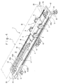
Fig. 4 is a perspective view of a vacuum processing apparatus showing a third embodiment of the present invention; -
Fig. 5 is a side view of an overall configuration thereof; -
Fig. 6 is a schematic sectional view showing the overall configuration; -
Fig. 7 is a schematic sectional side view of a vacuum processing apparatus showing a fourth embodiment of the present invention; -
Fig. 8 is a schematic sectional side view of a vacuum processing apparatus showing a fifth embodiment of the present invention; and -
Fig. 9 is a side view showing an overall configuration thereof. - Hereinafter, a non-contact power supply device according to an embodiment of the present invention when used in a vacuum processing apparatus that is used with the inside of the closed container maintained at a pressure lower than the atmospheric pressure will be described as an example. This vacuum processing apparatus is used for conveying an object to be processed such as a semiconductor wafer substrate or a glass substrate or performing other processes.
- As shown in
Fig. 1 , avacuum processing apparatus 1 in the first embodiment includes a closed container (referred to also as vacuum container) 2, a movingunit 3, and a non-contactpower supply device 4. First, the schematic configuration of thevacuum processing apparatus 1 except the non-contactpower supply device 4 will be described. - The closed
container 2 is formed into a rectangular parallelepiped shape as a whole and is defined by anouter wall 20 between the inner and outer sides of the closedcontainer 2. The inside of the closedcontainer 2 is formed as avacuum chamber 22. A pair of rails are installed parallel to each other on both sides of abottom wall 21 of the closed container 2 (not shown). The movingunit 3 includes amovable body 8 in the form of a box that is guided to move along the pair of rails, apower supply transformer 14 configured to be movable with the movement of themovable body 8, and a drive unit (load) 10 that is constituted by a motor or the like and is arranged inside themovable body 8. The moving path of themovable body 8 is a path extending in a direction along the longitudinal direction of the closedcontainer 2. - Next, the non-contact
power supply device 4 having a characteristic configuration of the present invention will be described. The non-contactpower supply device 4 includes a highfrequency power supply 12,feed lines 13, thepower supply transformer 14, andheat dissipators 15. The highfrequency power supply 12 is arranged outside the closedcontainer 2 and is connected to acommercial power supply 16. Since thefeed lines 13 are primary feed lines, thefeed lines 13 are hereinafter referred to asprimary feed lines 13. Theprimary feed lines 13 include two feed line parts of a firstfeed line part 131 and a secondfeed line part 132 as forward and return paths. The firstfeed line part 131 and the secondfeed line part 132 are made of electrically conductive materials (for example, aluminum) so as to have a circular cross section, though not shown in the figures. - The first
feed line part 131 and the secondfeed line part 132 respectively havelinear feed regions feed regions container 2. The positions of thefeed regions feed regions bottom wall 21 at a certain height. Thefeed regions container 2. The firstfeed line part 131 and the secondfeed line part 132 are arranged along the above-described pair of rails and between the pair of rails. - The portions on one end side (portions on one end side in the longitudinal direction) of the first
feed line part 131 and the secondfeed line part 132 are integrated together by being bent continuously. The portions on the other end side of the firstfeed line part 131 and the secondfeed line part 132 are bent downward at a right angle and extend to be exposed outside theclosed container 2 via avacuum seal mechanism 18 mounted on thebottom wall 21. This allows the two portions on the other end side of the firstfeed line part 131 and the secondfeed line part 132 to serve as cylindrical (rod-shaped)heat dissipators 15. The heat dissipators 15 that are the portions on the other end side are electrically connected to the highfrequency power supply 12. - In this embodiment, a core 19 made of a magnetic material and a pickup coil constituted by a secondary winding 191 are arranged opposed to the
primary feed lines 13, thereby forming thepower supply transformer 14. Specifically, as shown inFig. 2 , thepower supply transformer 14 includes the core 19 magnetically coupled to theprimary feed lines 13 in a non-contact manner, the secondary winding 191 provided in thecore 19, abase 7 attached onto the upper end surface of thepower supply transformer 14, and a pair of lockingmembers 140 for attaching thebase 7 onto the upper end surface of thepower supply transformer 14. - The
core 19 is held in a floating like state above thebottom wall 21, and the electric power supplied to the firstfeed line part 131 and the secondfeed line part 132 is configured to be supplied toward the core 19 side in a non-contact manner. Thecore 19 includes abase part 190A, twoleg parts 190B hanging from both sides of thebase part 190A, and oneleg part 190C hanging from the center of thebase part 190A. Thecore 19 is formed to have an E-shaped cross section that is open downward. The secondary winding 191 is wound around theleg part 190C at the center. Thefeed region 131A and thefeed region 132A of theprimary feed lines 13 are respectively inserted into the upper sides of the two spaces between the oneleg 190C at the center and the twoleg parts 190B on both sides. In order to fix the secondary winding 191 to theleg part 190C, it is conceivable to fill the gaps between thebase part 190A and thefeed regions core 19. - The pair of locking
members 140 are locked in the vertical directions respectively byflanges 19a formed to project laterally at the upper end of thecore 19. The lockingmembers 140 each have the same length as thecore 19 and are provided respectively at both ends of the upper end of thecore 19. The center portion of thebase 7 is placed on the upper end surface of the core 19, and the lateral portions of thebase 7 on both sides are placed on the upper end surfaces of the lockingmembers 140. The lockingmembers 140 are brought into pressure contact with theflanges 19a of the core 19 by screwing mountingscrews 8a from above thebase 7 to the lockingmembers 140 via thebase 7, so that thebase 7 is fixed to the upper end surface of thecore 19. - In the
vacuum processing apparatus 1 including the non-contactpower supply device 4 configured as above, electric power is supplied from the secondary winding 191 to adrive unit 10 due to electromagnetic induction from the magnetic field generated by electric power (high-frequency current) supplied from the highfrequency power supply 12 to thefeed regions feed line part 131 and the second feed line part 132). Thefeed regions core 19, and the secondary winding 191 are arranged inside theclosed container 2, thereby allowing theprimary feed lines 13 to be directly opposed to thepower supply transformer 14. Therefore, high coupling coefficient can be ensured. Thedrive unit 10 is driven by the supplied power, and themovable body 8 linearly moves back and forth along the moving path in thevacuum chamber 22 inside theclosed container 2. - When electric power is supplied from the high
frequency power supply 12 to thefeed regions primary feed lines 13, a loss occurs. This loss turns into heat to increase the temperature of the primary feed lines 13. In particular, in this embodiment, electric power is supplied from the highfrequency power supply 12 to thefeed regions primary feed lines 13 easily increases. Further, thefeed regions vacuum chamber 22 and are thus in an environment in which heat dissipation is particularly difficult. - Generally, heat-conduction, convection, and radiation are known as heat dissipation methods. However, in the case where the
primary feed lines 13 that are heating elements are arranged in theclosed container 2, which is a closed space, effects of heat-conduction and convection decrease, as compared with the case where theprimary feed lines 13 are arranged in an open container, to increase the temperature of theprimary feed lines 13 and the temperature inside theclosed container 2. In the case where the pressure inside theclosed container 2 is set to a pressure lower than the atmospheric pressure (for example, to a vacuum state), the effects of heat dissipation by heat-conduction and convection further decrease. In particular, at a degree of vacuum equal to or higher than the high vacuum state, heat-conduction and convection are ineffective, and therefore the heat dissipation performance considerably decreases. In other words, theprimary feed lines 13 can possibly overheat in the non-contactpower supply device 4 by the heat generated in theprimary feed lines 13 as a loss. - However, in the non-contact
power supply device 4 in this embodiment, theheat dissipators 15 that are connected to thefeed regions closed container 2 are provided. The heat generated in thefeed regions closed container 2, and therefore thefeed regions - Further, the
primary feed lines 13 partially extend outside theclosed container 2, and the extending portions are used as theheat dissipators 15. Since the extending portions of theprimary feed lines 13 serve also as theheat dissipators 15, the number of parts used for heat dissipation inside theclosed container 2 can be reduced. - Various modifications can be made without departing from the gist of the present invention. Further, the specific configuration of each part also is not limited to the above-described embodiment. Here, a second embodiment of the present invention will be described with reference to
Fig. 3 . In the second embodiment, thefeed regions feed line part 131 and the secondfeed line part 132 are arranged inside theclosed container 2, and portions on one end side and portions on the other end side of the firstfeed line part 131 and the secondfeed line part 132 extend from thebottom wall 21 to the outside of theclosed container 2 via thevacuum seal mechanism 18. - Then, the portions of the first
feed line part 131 and the secondfeed line part 132 that extend outside theclosed container 2 are configured to be used as theheat dissipators 15. In the same manner as in the first embodiment, the highfrequency power supply 12 is connected to theheat dissipators 15 that are the portions on one end side of the firstfeed line part 131 and the secondfeed line part 132. Further, theheat dissipators 15 that are the portions on the other end side of the firstfeed line part 131 and the secondfeed line part 132 are electrically connected to each other outside theclosed container 2. - Other configurations are the same manner as in the first embodiment, and thus the description thereof is not repeated. According to the second embodiment, the portions on the other end side of the first
feed line part 131 and the secondfeed line part 132 are connected to each other so as to be exposed outside theclosed container 2, instead of being connected inside theclosed container 2. Therefore, the number of theheat dissipators 15 is increased, as compared with the first embodiment. Therefore, the heat dissipation performance is further improved. Further, since the portions on the other end side of the firstfeed line part 131 and the secondfeed line part 132 are not connected to each other inside theclosed container 2, theheat dissipators 15 can be easily extended. Other actions and effects are the same as in the first embodiment. - With reference to
Fig. 4 to Fig. 6 , a third embodiment of the present invention will be described. Thevacuum processing apparatus 1 in the third embodiment includes theclosed container 2, the movingunit 3, and the non-contactpower supply device 4. - The
closed container 2 is formed into a rectangular parallelepiped shape as a whole and is defined by anouter wall 20 between the inner and outer sides of theclosed container 2. The inside of theclosed container 2 is formed as avacuum chamber 22. A pair ofrails 5 extending along the longitudinal direction of theclosed container 2 are installed parallel to each other on both sides of thebottom wall 21 of the closed container 2 (seeFig. 4 ). The movingunit 3 includes thebase 7 attached to and supported by the pair ofrails 5 via foursupport legs 6, themovable body 8 in the form of a box placed on and supported by thebase 7, thepower supply transformer 14 configured to be movable with the movement of themovable body 8, and the drive unit (load) 10 that is constituted by a motor or the like and is arranged inside themovable body 8. The moving path of themovable body 8 is formed by the pair ofrails 5. That is, the moving path extends in a direction along the longitudinal direction of theclosed container 2. - Next, the non-contact
power supply device 4 having a characteristic configuration of the present invention will be described. The non-contactpower supply device 4 includes the highfrequency power supply 12, the feed lines 13, thepower supply transformer 14, and theheat dissipators 15. The highfrequency power supply 12 is arranged outside theclosed container 2 and is connected to thecommercial power supply 16. The feed lines 13 are primary feed lines and includes two firstfeed line parts 131 and two secondfeed line parts 132 as four feed line parts for forward and return paths. The firstfeed line parts 131 and the secondfeed line parts 132 are respectively arranged parallel to each other between the pair ofrails 5. The firstfeed line parts 131 and the secondfeed line parts 132 are each made of an electrically conductive material (for example, aluminum) so as to have a circular cross section. - The first
feed line parts 131 and the secondfeed line parts 132 are respectively divided at the same position in the longitudinal direction into two, which are arranged at an interval in the longitudinal direction. The firstfeed line parts 131 on one end side in the longitudinal direction and on the other end side in the longitudinal direction and the secondfeed line parts 132 on one end side in the longitudinal direction and on the other end side in the longitudinal direction have the same configuration with only a difference in their arrangement. Therefore, the firstfeed line part 131 on one end side in the longitudinal direction and the secondfeed line part 132 on one end side in the longitudinal direction will be described below, and this description will be used also as description for the firstfeed line part 131 on the other end side in the longitudinal direction and the secondfeed line part 132 on the other end side in the longitudinal direction. - Hereinafter, the first
feed line part 131 on one side in the longitudinal direction is referred to as "the firstfeed line part 131 on one side", the firstfeed line part 131 on the other side in the longitudinal direction is referred to as "the firstfeed line part 131 on the other side", the secondfeed line part 132 on one side in the longitudinal direction is referred to as "the secondfeed line part 132 on one side", and the secondfeed line part 132 on the other side in the longitudinal direction is referred to as "the secondfeed line part 132 on the other side". - The first
feed line part 131 on one side and the secondfeed line part 132 on one side respectively include thelinear feed regions feed regions closed container 2. Thefeed regions support base 17 so that the positions of thefeed regions bottom wall 21 at a certain height (seeFig. 4 ). Thefeed regions rails 5 and between the pair ofrails 5. - The portions on one end side of the first
feed line part 131 and the second feed line part 132 (portions on one end side in the longitudinal direction) are bent downward at a right angle and extend to be exposed outside theclosed container 2 via thevacuum seal mechanism 18 mounted on thebottom wall 21. This allows the two portions on one end side of the firstfeed line part 131 and the secondfeed line part 132 to serve as the rod-shapedheat dissipators 15. The heat dissipators 15 that are the portions on one end side are electrically connected to the highfrequency power supply 12. The portions on the other end side of the firstfeed line part 131 and the secondfeed line part 132 are bent downward at a right angle and extend to be exposed outside theclosed container 2 via thevacuum seal mechanism 18 mounted on thebottom wall 21. This allows the two portions on the other end side of the firstfeed line part 131 and the secondfeed line part 132 to serve as the rod-shapedheat dissipators 15. - In this embodiment, the
heat dissipators 15 are specified as regions exposed outside theclosed container 2, but can be specified as portions other than thefeed regions feed line part 131 and the secondfeed line part 132. - Relative to the first
feed line part 131 on one side, the firstfeed line part 131 on the other side having the same configuration as in the firstfeed line part 131 on one side is provided at an interval in the longitudinal direction. Relative to the secondfeed line part 132 on one side, the secondfeed line part 132 on the other side having the same configuration as in the secondfeed line part 132 on one side is provided at an interval in the longitudinal direction. - The first
feed line parts 131 have the same configuration, and the secondfeed line parts 132 have the same configuration. The two portions on one end side and the two portions on the other end side of the firstfeed line part 131 on the other end side and the secondfeed line part 132 on the other end side extend to be exposed outside theclosed container 2 via thevacuum seal mechanism 18 mounted on thebottom wall 21. This allows the two portions on one side and the two portions on the other side of the firstfeed line part 131 on the other end side and the secondfeed line part 132 on the other end side to serve as the rod-shapedheat dissipators 15. That is, eightheat dissipators 15 are provided in the third embodiment. Theheat dissipators 15 are integrally formed by bending the firstfeed line parts 131 or the secondfeed line parts 132, and therefore thefeed regions heat dissipators 15 so as to be capable of transferring heat. Further, thefeed regions heat dissipators 15. In this case, theheat dissipators 15 function also as the feed lines 13. - The portion on the other end side of the first
feed line part 131 on one side and the portion on one end side of the firstfeed line part 131 on the other side, that is, theheat dissipators 15 of the two firstfeed line parts 131 are electrically connected to each other. The portion on the other end side of the secondfeed line part 132 on one side and the portion on one end side of the secondfeed line part 132 on the other side, that is, theheat dissipators 15 of the two secondfeed line parts 132 are electrically connected to each other. Further, the portion on the other end side of the firstfeed line part 131 on the other side and the portion on the other end side of the secondfeed line part 132 on the other side, that is, theheat dissipators 15 are electrically connected to each other. - The configuration of the
power supply transformer 14 is the same as in the first embodiment, and thus the description thereof is not repeated. However, in this embodiment, a plurality ofpower supply transformers 14 are provided adjacent to each other in the longitudinal direction, as shown inFig. 5 . - In the
vacuum processing apparatus 1 including the non-contactpower supply devices 4 configured as above, electric power is supplied from the secondary winding 191 to thedrive unit 10 due to electromagnetic induction from the magnetic field generated by electric power (high-frequency current) supplied from the highfrequency power supply 12 to thefeed regions feed line parts 131 and the second feed line parts 132). Thefeed regions power supply transformers 14 are arranged inside theclosed container 2, and thefeed regions power supply transformers 14, so that the coupling coefficient can be ensured. Thedrive unit 10 is driven by the supplied power, and themovable body 8 linearly moves back and forth along the moving path together with thesupport legs 6 in thevacuum chamber 22 inside theclosed container 2, while thesupport legs 6 are guided by the pair ofrails 5. - When electric power is supplied from the high
frequency power supply 12 to thefeed regions frequency power supply 12 to thefeed regions feed lines 13 easily increases. Further, thefeed regions vacuum chamber 22, and thus are in an environment in which heat dissipation is particularly difficult. - However, in the non-contact
power supply device 4 in this embodiment, the fourheat dissipators 15 including two portions on one end side that are connected to thefeed regions closed container 2 are provided. The heat generated in thefeed regions closed container 2, and therefore thefeed regions - Other actions and effects are the same as in the second embodiment. Moreover, according to the third embodiment, the vacuum processing apparatus 1 (the vacuum chamber 22) having a desired length in the longitudinal direction can be easily obtained by adding (extending) the first
feed line part 131 and the secondfeed line part 132 having the same configuration as the firstfeed line parts 131 and the secondfeed line parts 132 described above further in the longitudinal direction, and connecting theheat dissipators 15 thereof to each other. - Conversely, it is also possible to further divide the first
feed line parts 131 and the secondfeed line parts 132 to be shorter. This increases the number ofheat dissipators 15 that can be arranged in oneclosed container 2, and thus the heat dissipation performance can be improved to such an extent. - A fourth embodiment of the present invention will be described with reference to
Fig. 7 . In the fourth embodiment, the firstfeed line part 131 and the secondfeed line part 132 are each divided into three in the longitudinal direction and are arranged at intervals in the longitudinal direction. The firstfeed line part 131 and the secondfeed line part 132 are each divided into three in the longitudinal direction, thereby providing threefeed regions feed line part 131 and the secondfeed line part 132. - The divided positions of the first
feed line part 131 and the divided positions of the secondfeed line part 132 are displaced from each other in the longitudinal direction. The portions on both sides in the longitudinal direction of the firstfeed line part 131 and the secondfeed line part 132 extend from thebottom wall 21 via thevacuum seal mechanism 18 to be exposed outside theclosed container 2 respectively at the divided positions of the firstfeed line part 131 and the divided positions of the secondfeed line part 132, so as to serve as theheat dissipators 15. - The heat dissipators 15 in the middle portions in the longitudinal direction of the first
feed line part 131 are electrically connected to each other. The heat dissipators 15 in the middle portions in the longitudinal direction of the secondfeed line part 132 are electrically connected to each other. Further, the twoheat dissipators 15 at the ends on one side in the longitudinal direction are connected to the highfrequency power supply 12 outside theclosed container 2. The twoheat dissipators 15 at the ends on the other side in the longitudinal direction are connected to each other. - The amount of the above-described displacement in the longitudinal direction between the divided positions of the first
feed line part 131 and the divided positions of the secondfeed line part 132 is set so that only one of the intervals in the longitudinal direction of the divided positions of the firstfeed line part 131 and the divided positions of the secondfeed line part 132 is present at the position where the power supply transformer 14 (specifically, the core 19) is present, regardless of the position of thepower supply transformer 14. Other configurations are the same as in the third embodiment. Therefore, components having the same functions are denoted by the same reference numerals and the description thereof is not repeated. - According to the above-described configuration, the divided positions of the feed line parts (that is, portions where the feed regions are not present) at the position where the
power supply transformer 14 is present can be halved as compared with the third embodiment. Therefore, even if the firstfeed line part 131 divided and thus having joint portions is combined with the secondfeed line part 132 divided and thus having joint portions, a decrease in output at the joint portions can be reduced to half. - A fifth embodiment will be described with reference to
Fig. 8 andFig. 9 . In the non-contactpower supply device 4 in the fifth embodiment, the firstfeed line part 131 is divided in the longitudinal direction into two, which are arranged at an interval in the longitudinal direction. The firstfeed line part 131 on one side and the firstfeed line part 131 on the other side are electrically connected to each other by a first feed line part (feed line for joint) 1311 at the center. The dimension in the longitudinal direction of the firstfeed line part 1311 at the center is set to be shorter than the dimension in the longitudinal direction of the firstfeed line parts 131 on both sides. The entirety in the longitudinal direction of the firstfeed line part 1311 at the center serves as a feed region. - The second
feed line part 132 is divided in the longitudinal direction into two, which are arranged at an interval in the longitudinal direction. The secondfeed line part 132 on one side and the secondfeed line part 132 on the other side are electrically connected to each other by a second feed line part (feed line for joint) 1321 at the center. The dimension in the longitudinal direction of the secondfeed line part 1321 at the center is set to be shorter than the dimension in the longitudinal direction of the secondfeed line parts 132 on both sides. - The first
feed line parts member 133 made of an electrically conductive material. The secondfeed line parts member 133 made of an electrically conductive material. As shown inFig. 9 , the connectingmember 133 is in the form of an L-shaped angle and includes a mountingpiece 133a in the form of a flat plate and a hangingpart 133b hanging from an end in the longitudinal direction of the mountingpiece 133a. - In a portion in which the first
feed line parts parts 133b of a pair of connectingmembers 133 are arranged to be opposed to each other in the longitudinal direction. In a portion in which the secondfeed line parts parts 133b of a pair of connectingmembers 133 are arranged so as to be opposed to each other in the longitudinal direction. Then, ends in the longitudinal direction of the firstfeed line parts 131 and the secondfeed line parts 132 are placed on the mountingpieces 133a of the connectingmembers 133 and are screwed thereon. - The upper end of a round bar (which may be a square bar) serving as a
heat dissipator 15 made of an electrically conductive material is sandwiched between the pair of hangingparts 133b of the pair of connectingmembers 133. Thus, theheat dissipator 15 is connected to theprimary feed lines 13 so as to be capable of conducting heat. - In other words, the upper end side of the
heat dissipator 15 is connected to the firstfeed line parts heat dissipator 15 extends downward perpendicularly to the firstfeed line parts bottom wall 21 of theclosed container 2. Further, the upper end side of theheat dissipator 15 is connected to the secondfeed line parts heat dissipator 15 extends downward perpendicularly to the secondfeed line parts bottom wall 21 of theclosed container 2. - Pairs of connecting
members 133 are also connected to both ends of the firstfeed line parts 131 and the secondfeed line parts 132 on both sides in the longitudinal direction. Theheat dissipators 15 are electrically connected to the connectingmembers 133 so as to be capable of conducting heat.Vacuum seal mechanisms 18 configured to close the gaps with theheat dissipators 15 are provided in through holes of thebottom wall 21 through which theheat dissipators 15 connected to both ends of the firstfeed line parts 131 and the secondfeed line parts 132 pass. - A pair of
heat dissipators 15 at the ends on one side in the longitudinal direction are connected to the highfrequency power supply 12, and are electrically connected to the firstfeed line parts 131 or the secondfeed line parts 132 so as to be capable of conducting heat. A pair ofheat dissipators 15 arranged at the ends on the other side in the longitudinal direction are electrically connected to each other, and are electrically connected to the firstfeed line parts 131 or the secondfeed line parts 132 so as to be capable of conducting heat. This configuration allows the heat generated in the firstfeed line parts 131 and the secondfeed line parts 132 to be dissipated by theheat dissipators 15 outside theclosed container 2. - In the fifth embodiment, the first
feed line part 131 and the secondfeed line part 132 are each divided into two, which are connected by the first feed line parts (feed lines for joint) 1311 and 1321 at the center. Therefore, as compared with the case of forming one feed line with the same length in the longitudinal direction, the heat generated in the firstfeed line parts feed line parts - Further, the
heat dissipators 15 are hung from the firstfeed line part 1311 and the secondfeed line part 1321, and are configured to have a T-shape in side view when combined with the firstfeed line part 131 and the secondfeed line part 132. This configuration allows the firstfeed line part 1311 and the secondfeed line part 1321 to ensure electric path portions. Feed regions are formed over the entirety in the longitudinal direction without providing intervals at divided positions between the feed line parts. Accordingly, a decrease in output of thepower supply transformer 14 is suppressed, even if the feed line parts are divided. - Further, a high-frequency current flows through the first
feed line part 1311 and the secondfeed line part 1321, but theheat dissipators 15 are simply hung therefrom. Therefore, the high-frequency current does not flow through theheat dissipators 15. Therefore, there is no increase in temperature of theheat dissipators 15 due to energization. This configuration facilitates dissipation of heat generated in the firstfeed line parts feed line parts heat dissipators 15, and therefore the heat dissipation efficiency is improved. - In the fifth embodiment, the case where the first
feed line part 1311 and the secondfeed line part 1321 are arranged one by one for thefeed regions feed regions feed line parts 1311 and secondfeed line parts 1321 that are feed lines for joint. In this case, a position in which the firstfeed line part 1311 and the secondfeed line part 1321 are arranged is set to be present for each position where thepower supply transformer 14 is present, regardless of the moved position of thepower supply transformer 14. As a result, eddy currents generated due to thepower supply transformer 14 being present at a position opposed to theheat dissipators 15 are averaged, so that a reduction in conversion efficiency into power by thepower supply transformer 14 and variation in output of thepower supply transformer 14 are suppressed, thereby allowing stable output to be obtained. - Summary of the aforementioned explanation is described. The non-contact
power supply device 4 according to the above-described embodiments that is used in thevacuum processing apparatus 1 including theclosed container 2 and the movingunit 3 configured to be movable inside theclosed container 2 and that is capable of supplying electric power to the movingunit 3 from outside theclosed container 2 includes: a feed unit and theheat dissipators 15, wherein the feed unit includes the feed lines 13 (131 and 132) and thepower supply transformer 14, the feed lines 13 (131 and 132) have thefeed regions unit 3 inside theclosed container 2, thepower supply transformer 14 is arranged inside theclosed container 2 so as to be opposed to thefeed regions unit 3, and theheat dissipators 15 include portions on one end side connected to thefeed regions closed container 2. - In the non-contact
power supply device 4 according to the above-described embodiments, electric power to move the movingunit 3 is supplied from thefeed regions unit 3 via thepower supply transformer 14. The electric power applied to thefeed regions heat dissipators 15 are connected to thefeed regions closed container 2. Therefore, the heat generated in the feed lines 13 (131 and 132) as a loss is dissipated, even if the feed lines 13 (131 and 132) are arranged inside theclosed container 2 so that thefeed regions power supply transformer 14 in a non-contact manner. - In the non-contact
power supply device 4 according to the above-described embodiments, a configuration in which the portions on one end side of theheat dissipators 15 are electrically connected to thefeed regions heat dissipators 15 to thefeed regions - When the electric power to be supplied to the
feed regions closed container 2 through the portions on the other end side of theheat dissipators 15, as in the above-described configuration, the feed lines 13 (131 and 132) can serve also as theheat dissipators 15. - In the non-contact
power supply device 4 according to the above-described embodiments, a configuration in which a plurality of connecting parts (1311 and 1321) configured to connect the portions on one end side of theheat dissipators 15 to thefeed regions feed regions power supply transformer 14 is present, regardless of the position of thepower supply transformer 14, can be employed. - According to the above-described configuration, even if the plurality of connecting parts (1311 and 1321) are arranged in the portions on one end side of the
heat dissipators 15 and thefeed regions power supply transformer 14 is present, regardless of the moved position of thepower supply transformer 14. Therefore, eddy currents generated due to thepower supply transformer 14 being present at a position opposed to theheat dissipators 15 are averaged, so that variation in output of thepower supply transformer 14 is suppressed. - In the non-contact
power supply device 4 according to the above-described embodiments, a configuration in which theclosed container 2 is capable of maintaining its internal pressure lower than the atmospheric pressure can be employed. - According to the above-described configuration, heat dissipation is made difficult in the
feed regions closed container 2 than in the case of the atmospheric pressure, particularly, by maintaining the internal pressure of theclosed container 2 lower than the atmospheric pressure. Even in such a case, the heat generated in thefeed regions heat dissipators 15 outside theclosed container 2. - The
vacuum processing apparatus 1 according to the above-described embodiments includes theclosed container 2, the movingunit 3 provided inside theclosed container 2 so as to be movable inside theclosed container 2, and the non-contactpower supply device 4. - As described above, in the
vacuum processing apparatus 1 according to the above-described embodiments, the electric power applied to thefeed regions heat dissipators 15 are connected to thefeed regions closed container 2. Therefore, even if thefeed regions closed container 2 so as to be opposed to thepower supply transformer 14 in a non-contact manner, the heat generated in the feed lines 13 (131 and 132) as a loss is dissipated. - In the above-described embodiments, it is matter of course that a cable coated with an insulating layer may be used for the primary feed lines. Further, aluminum is mentioned in the above-described embodiments as an example of the primary feed lines, but the primary feed lines may be of copper materials, or other conductor materials.
- In the case of using a cable for the primary feed lines, the primary feed lines are coated with an insulating layer. For the above-described reasons, the heat generated in the
primary feed lines 13 as a loss may possibly cause theprimary feed lines 13 to overheat in the non-contactpower supply device 4. Such overheating causes burnout of the insulating layer of theprimary feed lines 13, or causes a gas to be generated from the insulating layer or the feed lines as conductors, in addition to the burnout. The gas reduces the degree of vacuum inside theclosed container 2. - However, in the present invention, the
heat dissipators 15 that are connected to the feed regions so as to be capable of conducting heat thereto and extend outside theclosed container 2 are provided, and the heat generated in the feed regions is partially dissipated from theheat dissipators 15 outside theclosed container 2. Therefore, the heat does not cause thefeed regions primary feed lines 13 is not burned out, and the gas is not generated from the insulating layer and the feed lines due to the heat. Accordingly, the degree of vacuum inside theclosed container 2 is not reduced. - In the above-described embodiments, the heat dissipators are configured to extend from the bottom wall of the closed container to the outside. However, the heat dissipators can extend from an outer wall (including the top wall) of the closed container, which is not necessarily the bottom wall. Likewise, the feed lines also are not necessarily configured to be introduced or extend from the bottom wall of the closed container, and can be introduced or extend from an outer wall of the closed container, which is not necessarily the bottom wall. Likewise, the power supply transformer also is not limited to the configuration of being arranged on the bottom wall side of the closed container, and can be configured to move along an outer wall of the closed container, which is not necessarily the bottom wall.
- Further, in the above-described embodiments, the case of use in the vacuum processing apparatus in which the pressure inside the closed container is maintained lower than the atmospheric pressure is described as an example. However, the present invention can be applied in a processing apparatus in which the feed regions are arranged inside the closed container, and the pressure inside the closed container is maintained at atmospheric pressure.
Claims (5)
- A non-contact power supply device that is used in a processing apparatus including a closed container and a moving unit provided inside the closed container so as to be movable inside the closed container, and that is capable of supplying electric power to the moving unit from outside the closed container, the non-contact power supply device comprising:a feed unit; anda heat dissipator, whereinthe feed unit comprises a feed line and a power supply transformer,the feed line comprises a feed region arranged inside the closed container along the moving direction of the moving unit,the power supply transformer is arranged inside the closed container so as to be opposed to the feed region in a non-contact manner and is provided to move together with the moving unit, andthe heat dissipator comprises a portion on one end side connected to the feed region so as to be capable of conducting heat thereto and a portion on the other end side extending outside the closed container.
- The non-contact power supply device according to claim 1, wherein
the portion on one end side of the heat dissipator is electrically connected to the feed region, and electric power is supplied from the portion on the other end side of the heat dissipator to the feed region. - The non-contact power supply device according to claim 1 or 2, further comprising:a plurality of connecting parts configured to connect the portion on one end side of the heat dissipator to the feed region of the feed line, whereinthe plurality of connecting parts are arranged along the longitudinal direction of the feed region, so that an equal number of connecting parts are present at a position where the power supply transformer is present, regardless of the position of the power supply transformer.
- The non-contact power supply device according to any one of claims 1 to 3, wherein
the closed container is capable of maintaining its internal pressure lower than the atmospheric pressure. - A processing apparatus comprising:a closed container;a moving unit provided inside the closed container so as to be movable inside the closed container; andthe non-contact power supply device according to any one of claims 1 to 3.
Applications Claiming Priority (1)
| Application Number | Priority Date | Filing Date | Title |
|---|---|---|---|
| JP2015163983A JP6579434B2 (en) | 2015-08-21 | 2015-08-21 | Non-contact power supply device and processing device provided with non-contact power supply device |
Publications (2)
| Publication Number | Publication Date |
|---|---|
| EP3133640A1 true EP3133640A1 (en) | 2017-02-22 |
| EP3133640B1 EP3133640B1 (en) | 2019-10-16 |
Family
ID=57120996
Family Applications (1)
| Application Number | Title | Priority Date | Filing Date |
|---|---|---|---|
| EP16184477.4A Active EP3133640B1 (en) | 2015-08-21 | 2016-08-17 | Non-contact power supply device, and processing apparatus including non-contact power supply device |
Country Status (5)
| Country | Link |
|---|---|
| US (1) | US10411508B2 (en) |
| EP (1) | EP3133640B1 (en) |
| JP (1) | JP6579434B2 (en) |
| KR (1) | KR102501568B1 (en) |
| TW (1) | TWI707623B (en) |
Cited By (1)
| Publication number | Priority date | Publication date | Assignee | Title |
|---|---|---|---|---|
| US20220219920A1 (en) * | 2019-05-23 | 2022-07-14 | Optima consumer GmbH | Power supply module for a transport system, function unit, system, use, and arrangement |
Families Citing this family (2)
| Publication number | Priority date | Publication date | Assignee | Title |
|---|---|---|---|---|
| CN113678238A (en) * | 2019-03-27 | 2021-11-19 | 应用材料公司 | Magnetic levitation system and method for measuring the distance between at least one electromagnetic actuator and a ferromagnetic element |
| JP2021095609A (en) * | 2019-12-18 | 2021-06-24 | キヤノントッキ株式会社 | Film deposition device, film deposition method, and method for manufacturing electronic device |
Citations (3)
| Publication number | Priority date | Publication date | Assignee | Title |
|---|---|---|---|---|
| US6922324B1 (en) * | 2000-07-10 | 2005-07-26 | Christopher M. Horwitz | Remote powering of electrostatic chucks |
| US20100036523A1 (en) * | 2008-08-07 | 2010-02-11 | Sinfonia Technology Co., Ltd. | Vacuum processing apparatus |
| WO2011126228A1 (en) * | 2010-04-07 | 2011-10-13 | Park Jun Nam | Continuous power feeding system using non-contact power feeding device |
Family Cites Families (22)
| Publication number | Priority date | Publication date | Assignee | Title |
|---|---|---|---|---|
| JPS525103A (en) * | 1975-06-30 | 1977-01-14 | Mitsubishi Electric Corp | Electric car control system |
| JPS62296398A (en) * | 1986-06-16 | 1987-12-23 | 石川島播磨重工業株式会社 | Electrostatic particle separator of particle accelerator |
| DE4446779C2 (en) * | 1994-12-24 | 1996-12-19 | Daimler Benz Ag | Arrangement for the contactless inductive transmission of electrical power |
| JPH10225024A (en) * | 1997-02-13 | 1998-08-21 | Ishikawajima Harima Heavy Ind Co Ltd | Non-contact electric power supply facility |
| JP4059828B2 (en) * | 2003-09-12 | 2008-03-12 | 株式会社椿本チエイン | Non-contact power feeding device |
| KR100573769B1 (en) * | 2003-12-10 | 2006-04-25 | 삼성전자주식회사 | Non-contact feeder system |
| JP4788504B2 (en) * | 2006-07-12 | 2011-10-05 | 富士電機株式会社 | Power supply structure for plasma processing equipment |
| JP5362330B2 (en) * | 2007-12-18 | 2013-12-11 | 三洋電機株式会社 | Charging stand |
| JP5349862B2 (en) * | 2008-08-08 | 2013-11-20 | パナソニック株式会社 | Power pull-in device |
| JP5191311B2 (en) * | 2008-08-22 | 2013-05-08 | パナソニック株式会社 | Feeder connection device |
| JP5340017B2 (en) * | 2009-04-28 | 2013-11-13 | 三洋電機株式会社 | Built-in battery and charging stand |
| KR20110034773A (en) * | 2009-09-29 | 2011-04-06 | 삼성전자주식회사 | Wireless charger using a way of inductive coupling |
| JP5348183B2 (en) * | 2010-08-18 | 2013-11-20 | 三洋電機株式会社 | Battery built-in equipment and charger |
| JP2013070477A (en) * | 2011-09-21 | 2013-04-18 | Panasonic Corp | Non-contact power supply system |
| JP2013135040A (en) * | 2011-12-26 | 2013-07-08 | Sinfonia Technology Co Ltd | Heat dissipation mechanism and vacuum processing apparatus |
| JP2014017973A (en) * | 2012-07-09 | 2014-01-30 | Panasonic Corp | Non-contact power supply system |
| JP2014049560A (en) * | 2012-08-30 | 2014-03-17 | Tokyo Electron Ltd | Transfer base and transfer device |
| JP5914879B2 (en) * | 2012-10-31 | 2016-05-11 | パナソニックIpマネジメント株式会社 | Non-contact power supply system, movable device, and control method for power supply device of non-contact power supply system |
| ITMI20131016A1 (en) | 2013-06-19 | 2014-12-20 | I M A Ind Macchine Automatic He S P A | FEEDING SYSTEM IN A LIOFILIZING MACHINE FOR THE PHARMACEUTICAL SECTOR |
| JP6228499B2 (en) * | 2014-03-28 | 2017-11-08 | 株式会社Soken | Wireless power feeder for linear motion robot |
| JP2016165172A (en) * | 2015-03-06 | 2016-09-08 | セイコーエプソン株式会社 | Processing device |
| CN107565699B (en) * | 2016-06-30 | 2020-11-24 | 佳能株式会社 | Wireless power transmission system, control method, and storage medium |
-
2015
- 2015-08-21 JP JP2015163983A patent/JP6579434B2/en active Active
-
2016
- 2016-04-14 KR KR1020160045353A patent/KR102501568B1/en active IP Right Grant
- 2016-04-15 TW TW105111849A patent/TWI707623B/en active
- 2016-08-15 US US15/237,119 patent/US10411508B2/en active Active
- 2016-08-17 EP EP16184477.4A patent/EP3133640B1/en active Active
Patent Citations (4)
| Publication number | Priority date | Publication date | Assignee | Title |
|---|---|---|---|---|
| US6922324B1 (en) * | 2000-07-10 | 2005-07-26 | Christopher M. Horwitz | Remote powering of electrostatic chucks |
| US20100036523A1 (en) * | 2008-08-07 | 2010-02-11 | Sinfonia Technology Co., Ltd. | Vacuum processing apparatus |
| JP5470770B2 (en) | 2008-08-07 | 2014-04-16 | シンフォニアテクノロジー株式会社 | Vacuum processing equipment |
| WO2011126228A1 (en) * | 2010-04-07 | 2011-10-13 | Park Jun Nam | Continuous power feeding system using non-contact power feeding device |
Cited By (1)
| Publication number | Priority date | Publication date | Assignee | Title |
|---|---|---|---|---|
| US20220219920A1 (en) * | 2019-05-23 | 2022-07-14 | Optima consumer GmbH | Power supply module for a transport system, function unit, system, use, and arrangement |
Also Published As
| Publication number | Publication date |
|---|---|
| US10411508B2 (en) | 2019-09-10 |
| KR102501568B1 (en) | 2023-02-20 |
| US20170054325A1 (en) | 2017-02-23 |
| JP6579434B2 (en) | 2019-09-25 |
| KR20170022853A (en) | 2017-03-02 |
| JP2017041605A (en) | 2017-02-23 |
| TWI707623B (en) | 2020-10-11 |
| TW201709806A (en) | 2017-03-01 |
| EP3133640B1 (en) | 2019-10-16 |
Similar Documents
| Publication | Publication Date | Title |
|---|---|---|
| CN107408453B (en) | Coil unit for non-contact power transmission | |
| US10411508B2 (en) | Non-contact power supply device, and processing apparatus including non-contact power supply device | |
| JP6195627B2 (en) | Electromagnetic induction equipment | |
| JP2011181856A (en) | Assembly of induction apparatus | |
| US10840014B2 (en) | Coil unit, and power transmitting device, power receiving device and wireless power transmission system using the coil unit | |
| US10847310B2 (en) | Coil unit, and power transmitting device, power receiving device and wireless power transmission system using the coil unit | |
| JP2014039037A (en) | Power supply device system including transformer having transformer core with leg arranged in polygon | |
| JP6211028B2 (en) | Reactor device | |
| US10410784B2 (en) | Magnetic component | |
| US20180166208A1 (en) | Coil structure and magnetic component | |
| JP6237516B2 (en) | Power supply | |
| JP2014063768A (en) | Coil unit used for non-contact power supply system | |
| US10607760B2 (en) | Coil body | |
| JP2018107102A (en) | Plasma generation device | |
| WO2012032307A1 (en) | Planar transformer | |
| US11239021B2 (en) | Isolated converter | |
| JP4838753B2 (en) | Oil-filled stationary induction device | |
| KR20160136387A (en) | Doublesided flat inductor assembly | |
| KR101582451B1 (en) | Radiant heat structure and tramsformer having the same | |
| EP2942849B1 (en) | Circuit breaker box, and switching device for electric power | |
| CN111373496A (en) | Transformer and power conversion device | |
| US20240047125A1 (en) | Inductive apparatus with helical coil frame | |
| CN109952624B (en) | Non-contact power supply device and working machine | |
| JP2020078245A (en) | Coil unit, and power transmission device, power receiving device and wireless power transmission system including the coil unit | |
| JP2021082632A (en) | Stationary inductive electric machine |
Legal Events
| Date | Code | Title | Description |
|---|---|---|---|
| PUAI | Public reference made under article 153(3) epc to a published international application that has entered the european phase |
Free format text: ORIGINAL CODE: 0009012 |
|
| STAA | Information on the status of an ep patent application or granted ep patent |
Free format text: STATUS: THE APPLICATION HAS BEEN PUBLISHED |
|
| AK | Designated contracting states |
Kind code of ref document: A1 Designated state(s): AL AT BE BG CH CY CZ DE DK EE ES FI FR GB GR HR HU IE IS IT LI LT LU LV MC MK MT NL NO PL PT RO RS SE SI SK SM TR |
|
| AX | Request for extension of the european patent |
Extension state: BA ME |
|
| STAA | Information on the status of an ep patent application or granted ep patent |
Free format text: STATUS: REQUEST FOR EXAMINATION WAS MADE |
|
| 17P | Request for examination filed |
Effective date: 20170626 |
|
| RBV | Designated contracting states (corrected) |
Designated state(s): AL AT BE BG CH CY CZ DE DK EE ES FI FR GB GR HR HU IE IS IT LI LT LU LV MC MK MT NL NO PL PT RO RS SE SI SK SM TR |
|
| STAA | Information on the status of an ep patent application or granted ep patent |
Free format text: STATUS: EXAMINATION IS IN PROGRESS |
|
| 17Q | First examination report despatched |
Effective date: 20170915 |
|
| REG | Reference to a national code |
Ref country code: DE Ref legal event code: R079 Ref document number: 602016022468 Country of ref document: DE Free format text: PREVIOUS MAIN CLASS: H01L0021677000 Ipc: H01L0021683000 |
|
| GRAP | Despatch of communication of intention to grant a patent |
Free format text: ORIGINAL CODE: EPIDOSNIGR1 |
|
| STAA | Information on the status of an ep patent application or granted ep patent |
Free format text: STATUS: GRANT OF PATENT IS INTENDED |
|
| INTG | Intention to grant announced |
Effective date: 20190517 |
|
| RIC1 | Information provided on ipc code assigned before grant |
Ipc: H02J 50/10 20160101ALI20190503BHEP Ipc: H01L 21/683 20060101AFI20190503BHEP Ipc: H01L 21/677 20060101ALI20190503BHEP Ipc: H05K 7/20 20060101ALI20190503BHEP |
|
| GRAS | Grant fee paid |
Free format text: ORIGINAL CODE: EPIDOSNIGR3 |
|
| GRAA | (expected) grant |
Free format text: ORIGINAL CODE: 0009210 |
|
| STAA | Information on the status of an ep patent application or granted ep patent |
Free format text: STATUS: THE PATENT HAS BEEN GRANTED |
|
| AK | Designated contracting states |
Kind code of ref document: B1 Designated state(s): AL AT BE BG CH CY CZ DE DK EE ES FI FR GB GR HR HU IE IS IT LI LT LU LV MC MK MT NL NO PL PT RO RS SE SI SK SM TR |
|
| REG | Reference to a national code |
Ref country code: GB Ref legal event code: FG4D |
|
| REG | Reference to a national code |
Ref country code: CH Ref legal event code: EP |
|
| REG | Reference to a national code |
Ref country code: DE Ref legal event code: R096 Ref document number: 602016022468 Country of ref document: DE |
|
| REG | Reference to a national code |
Ref country code: IE Ref legal event code: FG4D |
|
| REG | Reference to a national code |
Ref country code: AT Ref legal event code: REF Ref document number: 1192123 Country of ref document: AT Kind code of ref document: T Effective date: 20191115 |
|
| REG | Reference to a national code |
Ref country code: NL Ref legal event code: FP |
|
| REG | Reference to a national code |
Ref country code: LT Ref legal event code: MG4D |
|
| REG | Reference to a national code |
Ref country code: AT Ref legal event code: MK05 Ref document number: 1192123 Country of ref document: AT Kind code of ref document: T Effective date: 20191016 |
|
| PG25 | Lapsed in a contracting state [announced via postgrant information from national office to epo] |
Ref country code: BG Free format text: LAPSE BECAUSE OF FAILURE TO SUBMIT A TRANSLATION OF THE DESCRIPTION OR TO PAY THE FEE WITHIN THE PRESCRIBED TIME-LIMIT Effective date: 20200116 Ref country code: AT Free format text: LAPSE BECAUSE OF FAILURE TO SUBMIT A TRANSLATION OF THE DESCRIPTION OR TO PAY THE FEE WITHIN THE PRESCRIBED TIME-LIMIT Effective date: 20191016 Ref country code: FI Free format text: LAPSE BECAUSE OF FAILURE TO SUBMIT A TRANSLATION OF THE DESCRIPTION OR TO PAY THE FEE WITHIN THE PRESCRIBED TIME-LIMIT Effective date: 20191016 Ref country code: PT Free format text: LAPSE BECAUSE OF FAILURE TO SUBMIT A TRANSLATION OF THE DESCRIPTION OR TO PAY THE FEE WITHIN THE PRESCRIBED TIME-LIMIT Effective date: 20200217 Ref country code: LV Free format text: LAPSE BECAUSE OF FAILURE TO SUBMIT A TRANSLATION OF THE DESCRIPTION OR TO PAY THE FEE WITHIN THE PRESCRIBED TIME-LIMIT Effective date: 20191016 Ref country code: SE Free format text: LAPSE BECAUSE OF FAILURE TO SUBMIT A TRANSLATION OF THE DESCRIPTION OR TO PAY THE FEE WITHIN THE PRESCRIBED TIME-LIMIT Effective date: 20191016 Ref country code: NO Free format text: LAPSE BECAUSE OF FAILURE TO SUBMIT A TRANSLATION OF THE DESCRIPTION OR TO PAY THE FEE WITHIN THE PRESCRIBED TIME-LIMIT Effective date: 20200116 Ref country code: GR Free format text: LAPSE BECAUSE OF FAILURE TO SUBMIT A TRANSLATION OF THE DESCRIPTION OR TO PAY THE FEE WITHIN THE PRESCRIBED TIME-LIMIT Effective date: 20200117 Ref country code: PL Free format text: LAPSE BECAUSE OF FAILURE TO SUBMIT A TRANSLATION OF THE DESCRIPTION OR TO PAY THE FEE WITHIN THE PRESCRIBED TIME-LIMIT Effective date: 20191016 Ref country code: LT Free format text: LAPSE BECAUSE OF FAILURE TO SUBMIT A TRANSLATION OF THE DESCRIPTION OR TO PAY THE FEE WITHIN THE PRESCRIBED TIME-LIMIT Effective date: 20191016 |
|
| PG25 | Lapsed in a contracting state [announced via postgrant information from national office to epo] |
Ref country code: HR Free format text: LAPSE BECAUSE OF FAILURE TO SUBMIT A TRANSLATION OF THE DESCRIPTION OR TO PAY THE FEE WITHIN THE PRESCRIBED TIME-LIMIT Effective date: 20191016 Ref country code: RS Free format text: LAPSE BECAUSE OF FAILURE TO SUBMIT A TRANSLATION OF THE DESCRIPTION OR TO PAY THE FEE WITHIN THE PRESCRIBED TIME-LIMIT Effective date: 20191016 Ref country code: IS Free format text: LAPSE BECAUSE OF FAILURE TO SUBMIT A TRANSLATION OF THE DESCRIPTION OR TO PAY THE FEE WITHIN THE PRESCRIBED TIME-LIMIT Effective date: 20200224 |
|
| PG25 | Lapsed in a contracting state [announced via postgrant information from national office to epo] |
Ref country code: AL Free format text: LAPSE BECAUSE OF FAILURE TO SUBMIT A TRANSLATION OF THE DESCRIPTION OR TO PAY THE FEE WITHIN THE PRESCRIBED TIME-LIMIT Effective date: 20191016 |
|
| REG | Reference to a national code |
Ref country code: DE Ref legal event code: R097 Ref document number: 602016022468 Country of ref document: DE |
|
| PG2D | Information on lapse in contracting state deleted |
Ref country code: IS |
|
| PG25 | Lapsed in a contracting state [announced via postgrant information from national office to epo] |
Ref country code: IS Free format text: LAPSE BECAUSE OF FAILURE TO SUBMIT A TRANSLATION OF THE DESCRIPTION OR TO PAY THE FEE WITHIN THE PRESCRIBED TIME-LIMIT Effective date: 20200216 Ref country code: CZ Free format text: LAPSE BECAUSE OF FAILURE TO SUBMIT A TRANSLATION OF THE DESCRIPTION OR TO PAY THE FEE WITHIN THE PRESCRIBED TIME-LIMIT Effective date: 20191016 Ref country code: ES Free format text: LAPSE BECAUSE OF FAILURE TO SUBMIT A TRANSLATION OF THE DESCRIPTION OR TO PAY THE FEE WITHIN THE PRESCRIBED TIME-LIMIT Effective date: 20191016 Ref country code: RO Free format text: LAPSE BECAUSE OF FAILURE TO SUBMIT A TRANSLATION OF THE DESCRIPTION OR TO PAY THE FEE WITHIN THE PRESCRIBED TIME-LIMIT Effective date: 20191016 Ref country code: EE Free format text: LAPSE BECAUSE OF FAILURE TO SUBMIT A TRANSLATION OF THE DESCRIPTION OR TO PAY THE FEE WITHIN THE PRESCRIBED TIME-LIMIT Effective date: 20191016 Ref country code: DK Free format text: LAPSE BECAUSE OF FAILURE TO SUBMIT A TRANSLATION OF THE DESCRIPTION OR TO PAY THE FEE WITHIN THE PRESCRIBED TIME-LIMIT Effective date: 20191016 |
|
| PLBE | No opposition filed within time limit |
Free format text: ORIGINAL CODE: 0009261 |
|
| STAA | Information on the status of an ep patent application or granted ep patent |
Free format text: STATUS: NO OPPOSITION FILED WITHIN TIME LIMIT |
|
| PG25 | Lapsed in a contracting state [announced via postgrant information from national office to epo] |
Ref country code: SM Free format text: LAPSE BECAUSE OF FAILURE TO SUBMIT A TRANSLATION OF THE DESCRIPTION OR TO PAY THE FEE WITHIN THE PRESCRIBED TIME-LIMIT Effective date: 20191016 Ref country code: SK Free format text: LAPSE BECAUSE OF FAILURE TO SUBMIT A TRANSLATION OF THE DESCRIPTION OR TO PAY THE FEE WITHIN THE PRESCRIBED TIME-LIMIT Effective date: 20191016 Ref country code: IT Free format text: LAPSE BECAUSE OF FAILURE TO SUBMIT A TRANSLATION OF THE DESCRIPTION OR TO PAY THE FEE WITHIN THE PRESCRIBED TIME-LIMIT Effective date: 20191016 |
|
| 26N | No opposition filed |
Effective date: 20200717 |
|
| PG25 | Lapsed in a contracting state [announced via postgrant information from national office to epo] |
Ref country code: SI Free format text: LAPSE BECAUSE OF FAILURE TO SUBMIT A TRANSLATION OF THE DESCRIPTION OR TO PAY THE FEE WITHIN THE PRESCRIBED TIME-LIMIT Effective date: 20191016 |
|
| PG25 | Lapsed in a contracting state [announced via postgrant information from national office to epo] |
Ref country code: MC Free format text: LAPSE BECAUSE OF FAILURE TO SUBMIT A TRANSLATION OF THE DESCRIPTION OR TO PAY THE FEE WITHIN THE PRESCRIBED TIME-LIMIT Effective date: 20191016 |
|
| REG | Reference to a national code |
Ref country code: CH Ref legal event code: PL |
|
| PG25 | Lapsed in a contracting state [announced via postgrant information from national office to epo] |
Ref country code: LI Free format text: LAPSE BECAUSE OF NON-PAYMENT OF DUE FEES Effective date: 20200831 Ref country code: LU Free format text: LAPSE BECAUSE OF NON-PAYMENT OF DUE FEES Effective date: 20200817 Ref country code: CH Free format text: LAPSE BECAUSE OF NON-PAYMENT OF DUE FEES Effective date: 20200831 |
|
| REG | Reference to a national code |
Ref country code: BE Ref legal event code: MM Effective date: 20200831 |
|
| PG25 | Lapsed in a contracting state [announced via postgrant information from national office to epo] |
Ref country code: BE Free format text: LAPSE BECAUSE OF NON-PAYMENT OF DUE FEES Effective date: 20200831 |
|
| PGFP | Annual fee paid to national office [announced via postgrant information from national office to epo] |
Ref country code: NL Payment date: 20210819 Year of fee payment: 6 |
|
| PGFP | Annual fee paid to national office [announced via postgrant information from national office to epo] |
Ref country code: FR Payment date: 20210819 Year of fee payment: 6 Ref country code: IE Payment date: 20210819 Year of fee payment: 6 |
|
| PGFP | Annual fee paid to national office [announced via postgrant information from national office to epo] |
Ref country code: DE Payment date: 20210819 Year of fee payment: 6 Ref country code: GB Payment date: 20210820 Year of fee payment: 6 |
|
| PG25 | Lapsed in a contracting state [announced via postgrant information from national office to epo] |
Ref country code: TR Free format text: LAPSE BECAUSE OF FAILURE TO SUBMIT A TRANSLATION OF THE DESCRIPTION OR TO PAY THE FEE WITHIN THE PRESCRIBED TIME-LIMIT Effective date: 20191016 Ref country code: MT Free format text: LAPSE BECAUSE OF FAILURE TO SUBMIT A TRANSLATION OF THE DESCRIPTION OR TO PAY THE FEE WITHIN THE PRESCRIBED TIME-LIMIT Effective date: 20191016 Ref country code: CY Free format text: LAPSE BECAUSE OF FAILURE TO SUBMIT A TRANSLATION OF THE DESCRIPTION OR TO PAY THE FEE WITHIN THE PRESCRIBED TIME-LIMIT Effective date: 20191016 |
|
| PG25 | Lapsed in a contracting state [announced via postgrant information from national office to epo] |
Ref country code: MK Free format text: LAPSE BECAUSE OF FAILURE TO SUBMIT A TRANSLATION OF THE DESCRIPTION OR TO PAY THE FEE WITHIN THE PRESCRIBED TIME-LIMIT Effective date: 20191016 |
|
| REG | Reference to a national code |
Ref country code: DE Ref legal event code: R119 Ref document number: 602016022468 Country of ref document: DE |
|
| REG | Reference to a national code |
Ref country code: NL Ref legal event code: MM Effective date: 20220901 |
|
| GBPC | Gb: european patent ceased through non-payment of renewal fee |
Effective date: 20220817 |
|
| PG25 | Lapsed in a contracting state [announced via postgrant information from national office to epo] |
Ref country code: NL Free format text: LAPSE BECAUSE OF NON-PAYMENT OF DUE FEES Effective date: 20220901 |
|
| PG25 | Lapsed in a contracting state [announced via postgrant information from national office to epo] |
Ref country code: IE Free format text: LAPSE BECAUSE OF NON-PAYMENT OF DUE FEES Effective date: 20220817 Ref country code: FR Free format text: LAPSE BECAUSE OF NON-PAYMENT OF DUE FEES Effective date: 20220831 Ref country code: DE Free format text: LAPSE BECAUSE OF NON-PAYMENT OF DUE FEES Effective date: 20230301 |
|
| PG25 | Lapsed in a contracting state [announced via postgrant information from national office to epo] |
Ref country code: GB Free format text: LAPSE BECAUSE OF NON-PAYMENT OF DUE FEES Effective date: 20220817 |