EP3133629A1 - Rotating input device - Google Patents
Rotating input device Download PDFInfo
- Publication number
- EP3133629A1 EP3133629A1 EP15761544.4A EP15761544A EP3133629A1 EP 3133629 A1 EP3133629 A1 EP 3133629A1 EP 15761544 A EP15761544 A EP 15761544A EP 3133629 A1 EP3133629 A1 EP 3133629A1
- Authority
- EP
- European Patent Office
- Prior art keywords
- rotary
- follower
- return
- holding
- input device
- Prior art date
- Legal status (The legal status is an assumption and is not a legal conclusion. Google has not performed a legal analysis and makes no representation as to the accuracy of the status listed.)
- Granted
Links
Images



Classifications
-
- H—ELECTRICITY
- H01—ELECTRIC ELEMENTS
- H01H—ELECTRIC SWITCHES; RELAYS; SELECTORS; EMERGENCY PROTECTIVE DEVICES
- H01H19/00—Switches operated by an operating part which is rotatable about a longitudinal axis thereof and which is acted upon directly by a solid body external to the switch, e.g. by a hand
- H01H19/02—Details
- H01H19/10—Movable parts; Contacts mounted thereon
- H01H19/11—Movable parts; Contacts mounted thereon with indexing means
-
- H—ELECTRICITY
- H01—ELECTRIC ELEMENTS
- H01H—ELECTRIC SWITCHES; RELAYS; SELECTORS; EMERGENCY PROTECTIVE DEVICES
- H01H19/00—Switches operated by an operating part which is rotatable about a longitudinal axis thereof and which is acted upon directly by a solid body external to the switch, e.g. by a hand
- H01H19/54—Switches operated by an operating part which is rotatable about a longitudinal axis thereof and which is acted upon directly by a solid body external to the switch, e.g. by a hand the operating part having at least five or an unspecified number of operative positions
- H01H19/56—Angularly-movable actuating part carrying contacts, e.g. drum switch
- H01H19/58—Angularly-movable actuating part carrying contacts, e.g. drum switch having only axial contact pressure, e.g. disc switch, wafer switch
-
- H—ELECTRICITY
- H01—ELECTRIC ELEMENTS
- H01H—ELECTRIC SWITCHES; RELAYS; SELECTORS; EMERGENCY PROTECTIVE DEVICES
- H01H3/00—Mechanisms for operating contacts
- H01H3/02—Operating parts, i.e. for operating driving mechanism by a mechanical force external to the switch
- H01H3/20—Operating parts, i.e. for operating driving mechanism by a mechanical force external to the switch wherein an auxiliary movement thereof, or of an attachment thereto, is necessary before the main movement is possible or effective, e.g. for unlatching, for coupling
Definitions
- the present invention relates to a rotary type input device having a function which returns a rotary member operating a rotation detection unit from an input rotation position at which the rotary member has rotated by a predetermined angle to a return rotation position.
- Patent Document 1 discloses a rotary switch which includes a return push button.
- the return push button is supported to be movable forward and backward at the center portion of a rotary knob.
- Multiple cam ridges are formed on an outer circumferential surface of the return push button in a circumferential direction at a constant pitch, and a leaf spring which is fitted to the cam ridges is provided in the rotary knob. If the rotary knob is rotated, the rotary knob is held at a rotation position at which the leaf spring and the cam ridge are fitted to each other, and a switch contact can be switched to states corresponding to each of the holding position.
- a return spring member configured of a spiral spring is provided between a case and the rotary knob.
- the return push button can be pressed, and a compression coil spring by which the return push button is returned when a pressing force is released is provided in the return push button. If the rotary knob rotates , the rotary knob is held in a state where the leaf spring and the cam ridge are fitted to each other, and if the return push button is pressed, the fitting between the leaf spring and the cam ridge is released, and the rotary knob is returned to an original position by a force of the return spring member. In addition, the return push button is returned to a posture before the return push button is pressed by an elastic force of the compression coil spring.
- Patent Document 1 Japanese Unexamined Utility Model Registration Application Publication No. H4-8331 (Microfilm of Japanese Utility Model Registration Application No. H2-48103 )
- the present invention is for solving the above-described problem of the related art, and an object thereof is to provide a rotary type input device in which a rotary member can be reliably returned to a return rotation position using fewer spring members.
- a rotary type input device which includes: a housing; a rotary member which is rotatably supported by the housing and is rotatable from a return rotation position to an input rotation position; and a rotation detection unit which changes a detection state according to the rotation of the rotary member, in which a cam portion which is formed in the rotary member, a follower which faces the cam portion, and a holding spring member which presses the follower to the cam portion are provided, and a holding recessed portion which is fitted to the follower to hold the rotary member when the rotary member rotates to the input rotation position is formed in the cam portion, a hold release member which releases the fitting between the follower and the holding recessed portion, and a return spring member which returns the rotary member to the return rotation position when the fitting is released are provided, and the hold release member is provided to be movable from an initial posture to a hold release posture at which the fitting is released, and is returned to the initial posture by the holding spring member.
- the rotary member is held at the input rotation position by the holding spring member, and the hold release member is returned to an initial posture by the same holding spring member. It is possible to reduce the number of spring members by providing two functions to the holding spring member.
- the follower or the holding spring member is pushed by the hold release member when the hold release member moves to the hold release posture, and the fitting between the follower and the holding recessed portion is released.
- a return recessed portion may be formed in the cam portion, the follower may face a bottom portion of the return recessed portion or an inclined portion adjacent to the bottom portion when the rotary member is returned to the return rotation position by return spring member, and the follower may be fitted to the return recessed portion by a biasing force of the holding spring member.
- the return spring member is set such that a fitting force between the follower and the holding recessed portion is stronger than a force which returns the rotary member positioned at the input rotation position to the return rotation position.
- a shaft portion which extends along a rotation center line and an extension portion which extends in a circumferential direction from the shaft portion may be integrally formed with each other in the rotary member, and the cam portion may be formed on the extension portion.
- the cam portion may be formed on an extension surface side which is an upper surface or a lower surface of the extension portion, and the follower may be biased in a direction intersecting the extension surface by the holding spring member, and may be pressed to the cam portion.
- the hold release member is supported to be movable forward and backward in the direction intersecting the extension surface.
- the cam portion may be formed along a circumferential end of the extension portion, and the follower may be biased toward the rotation center line by the holding spring member and may be pressed to the cam portion.
- the hold release member may be rotatably supported in a plane intersecting the rotation center line.
- the rotation detection unit includes a fixed contact and a sliding contact which slides on the fixed contact, the fixed contact is fixed to the housing, and the sliding contact is fixed to the extension portion.
- a shaft hole which extends along the rotation center line is formed in the shaft portion, a cylindrical rotary support portion is formed in the housing, and the shaft hole is rotatably supported on an outer circumferential surface of the rotary supporting portion.
- the inside of the housing is partitioned by a partition wall, the cam portion, the follower, the holding spring member, and the hold release member are provided in one space partitioned off by the partition wall, and the return spring member is provided in the other space.
- the holding spring member and the return spring member are provided in different spaces which are separated from each other in the state where the partition wall is interposed therebetween, two spring members do not come into contact with each other and do not interfere with each other, and it is possible to reliably perform operations with both springs.
- the hold release member since the hold release member is returned to the initial posture by the holding spring member which presses the follower to the cam portion, it is possible to reduce the number of springs.
- a rotary type input device 1 of a first embodiment of the present invention includes a housing 10.
- the housing 10 is configured of a lower housing 11, an upper housing 15, and a holding metal fitting 18.
- the lower housing 11 and the upper housing 15 are formed of synthetic resin materials, and the holding metal fitting 18 is formed of a metal plate material.
- the lower housing 11 includes an annular bottom portion 12, and a lower circumferential wall portion 13 which integrally extends upward (Y1 direction) from the outer circumferential edge of the bottom portion 12.
- a rotary supporting portion 14 which extends upward (Y1 direction) from the inner circumferential edge of the bottom portion 12 is integrally formed.
- the rotary supporting portion 14 has a cylindrical shape, a cylindrical hole 14a thereof is formed to penetrate the lower housing 11 in a vertical direction(Y1-Y2 direction), and as shown in Fig. 1 , the cylindrical hole 14a is formed to penetrate vertically the entire housing 10.
- a center line which is positioned at the center of the rotary supporting portion 14 and extends vertically is a rotation center line O.
- the upper housing 15 includes a partition wall 16 which is formed in a plane orthogonal to the rotation center line O, and a circular opening portion 16a is formed in the partition wall 16.
- An upper circumferential wall portion 17 is integrally formed upward (Y1 direction) from the outer circumferential edge of the partition wall 16.
- the lower housing 11 and the upper housing 15 vertically overlap each other, and are combined to be positioned to each other by recession/protrusion fitting or the like.
- the outer surfaces of the lower circumferential wall portion 13 and the upper circumferential wall portion 17 have the same shape as each other, and the outer surface of the lower circumferential wall portion 13 is approximately coincident with the outer surface of the upper circumferential wall portion 17 in a state where the lower housing 11 and the upper housing 15 are combined to each other.
- the holding metal fitting 18 includes a cover plate portion 18a, and a circular opening portion 18b is formed in the cover plate portion 18a.
- the holding metal fitting 18 includes a pair of first holding pieces 19a which is bent downward (Y2 direction) from the circumferential edge portion of the cover plate portion 18a, and multiple second holding pieces 19b.
- the pair of first holding pieces 19a is fitted to holding grooves 17a which are formed on the outer surface of the upper housing 15, and is fitted to holding grooves 13a which are formed on the outer surface of the lower housing 11.
- the multiple second holding pieces 19b elastically press the outer surface of the upper housing 15 and the outer surface of the lower housing 11, and bent portions 19c positioned on the lower end thereof are locked to the lower surface of the lower housing 11.
- the lower housing 11 and the upper housing 15 are elastically held by the holding metal fitting 18 to assemble the housing 10.
- the inside of the housing 10 is divided into a lower space S1 and an upper space S2 by the partition wall 16 of the upper housing 15.
- the lower space S1 is surrounded by the bottom portion 12 and the lower circumferential wall portion 13 of the lower housing 11, and the partition wall 16.
- the upper space S2 is surrounded by the partition wall 16 and the upper circumferential wall portion 17 of the upper housing 15 and the cover plate portion 18a of the holding metal fitting 18.
- a rotary member 20 is accommodated inside the housing 10.
- the rotary member 20 is formed of a synthetic resin material.
- a shaft portion 21, and a flanged extension portion 22 which spreads in the circumferential direction from the lower portion of the shaft portion 21 are integrally formed.
- the shaft portion 21 has a cylindrical shape, and a shaft hole 21a is formed to penetrate in the vertical direction (Y1-Y2 direction).
- the shaft hole 21a of the rotary member 20 is inserted into the outer side of the rotary supporting portion 14 of the lower housing 11.
- the upper portion of the shaft portion 21 of the rotary member 20 passes through the inside of the opening portion 16a formed in the partition wall 16 of the upper housing 15 and the inside of the opening portion 18b formed in the cover plate portion 18a of the holding metal fitting 18 to protrude upward, and the rotary member 20 slides on the outer circumferential surface of the rotary supporting portion 14 and can rotate about the rotation center line O.
- the extension portion 22 of the rotary member 20 is positioned inside the lower space S1 of the housing 10, and a lower surface 22a of the extension portion 22 is installed on a protrusion portion 12a which is formed to have a higher step (Y1 direction) upward than the bottom portion 12 of the lower housing 11 on the inner surface of the bottom portion 12.
- a rotation detection space S3 is formed on the outer circumferential side of the protrusion portion 12a, and a rotation detection unit 25 is accommodated inside the rotation detection space S3.
- the rotation detection unit 25 is configured of a fixed contact 26 and a sliding contact 27.
- the fixed contact 26 is fixed to the bottom portion 12 of the lower housing 11.
- the fixed contact 26 is embedded to the lower housing 11 by a so-called insert molding method, and the contact portion of the fixed contact 26 is exposed to the inner surface of the bottom portion 12.
- the contact portion is divided into multiple portions, and multiple terminals 26a continuous from the divided contact portions protrude downward from the lower housing 11.
- the sliding contact 27 is formed of a conductive metal plate having spring property, and in the sliding contact 27, a fixed ring portion 27a, and multiple sliders 27b which are branched from the fixed ring portion 27a and are bent downward (Y2 direction) are integrally formed.
- the fixed ring portion 27a is fixed to the extension portion 22 by caulking multiple fixation protrusions 28 which protrude from the lower surface 22a of the extension portion 22, and the sliders 27b can come into contact with the contact portion of the fixed contact 26.
- a cam portion 30 is integrally formed with an extension surface 22b facing the top of the extension portion 22 of the rotary member 20.
- the extension surface 22b which is the upper surface of the extension portion 22 is a surface intersecting the rotation center line O.
- the cam portion 30 includes a cam surface which faces upward (Y1 direction).
- the cam surface includes a return recessed portion 31, and includes a first holding recessed portion 32 and a second holding recessed portion 33 in this order in a ⁇ 2 direction from the return recessed portion 31.
- a third holding recessed portion 34 is formed in a ⁇ 1 direction from the return recessed portion 31.
- the lower surface of the extension portion 22 becomes an extension surface, and the cam portion 30 is formed on the lower surface.
- the return recessed portion 31 is configured of a bottom portion 31a, and inclined portions 31b and 31b which are continuous to be adjacent to both sides of the bottom portion 31a in the rotation direction.
- the first holding recessed portion 32 is also configured of a bottom portion 32a, and inclined portions 32b and 32b which are continuous to be adjacent to both sides of the bottom portion 32a.
- each of the second holding recessed portion 33 and the third holding recessed portion 34 is configured of a bottom portion and inclined portions which are continuous to be adjacent to both sides of the bottom portion.
- a boundary portion between the inclined portion 31b of the return recessed portion 31 and the inclined portion 32b of the first holding recessed portion 32 is a protrusion portion.
- a boundary portion between the first holding recessed portion 32 and the second holding recessed portion 33 also is a protrusion portion
- a boundary portion between the return recessed portion 31 and the third holding recessed portion 34 also is a protrusion portion.
- the holding spring member 35 is formed of a metal spring material and has a ring shape.
- a fixation portion 35a, and an elastic pressure portion 35c in which a portion of the ring is deformed downward (Y2 direction) are integrally formed.
- Attachment holes 35b are formed on the fixation portion 35a, and the fixation portion 35a is fixed to the lower surface 16b of the partition wall 16 of the upper housing 15 by caulking fixation protrusion (not shown) integrally formed with the upper housing 15 to the attachment holes 35b.
- the follower 36 facing the cam portion 30 is fixed to the center portion of the elastic pressure portion 35c of the holding spring member 35.
- the follower 36 is formed of a synthetic resin material, and in the follower 36, a sliding protrusion portion 36a which slides on the cam portion 30, and a pressing portion 36b which further extends in the direction separated from the rotation center line O than the sliding protrusion portion 36a and has a recessed portion facing downward are integrally formed.
- the follower 36 is biased in a downward direction which is the direction intersecting the extension surface 22b by an elastic force of the elastic pressure portion 35c of the holding spring member 35, and the follower 36 is pressed by the cam portion 30.
- the lower surface 22a of the extension portion 22 of the rotary member 20 is pressed to the protrusion portion 12a formed on the bottom portion 12 of the lower housing 11 by the elastic force of the elastic pressure portion 35c, and thus, rattling of the rotary member 20 inside the housing 10 in the direction along the rotation center line O is prevented.
- a pin-shaped (shaft-shaped) hold release member 37 is provided inside the lower space S1 of the housing 10.
- a sliding hole 12b which penetrates vertically is formed on the bottom portion 12 of the lower housing 11, and the hold release member 37 is inserted into the sliding hole 12b and is slidingly supported in the vertical direction (Y1-Y2 direction) which is the direction (the direction parallel to the rotation center line O) intersecting the extension surface 22b.
- a stopper 37b is integrally formed on the upper portion of the hold release member 37, and when the hold release member 37 is lowered to the initial posture shown in Fig. 1 , the stopper 37b comes into contact with the inner surface of the bottom portion 12 of the lower housing 11, and downward extraction of the hold release member 37 is prevented.
- a pressing operation portion 37c on the lower end portion of the hold release member 37 protrudes downward from the bottom portion 12 of the lower housing 10.
- a return spring member 4 0 and a spring support member 45 are accommodated inside the upper space S2 of the housing 10.
- the spring support member 45 is formed of a synthetic resin material and has a ring shape.
- a circular opening portion 46 is formed in the spring support member 45, and as shown in Fig. 1 , the opening portion 46 is inserted into the outer circumferential portion of the shaft portion 21 of the rotary member 20.
- Engagement protrusions 47 protruding from three locations toward the opening portion 46 are integrally formed on the spring support member 45. Each engagement protrusion 47 engages with an engagement groove 21b which is formed upward (Y1 direction) in the shaft portion 21 of the rotary member 20, and the spring support member 45 can rotate along with the rotary member 20.
- spring support member 45 As shown in Fig. 2 , in the spring support member 45, a pair of spring hook portions 48a and 48b which protrudes upward are integrally formed at two locations. In the upper housing 15, spring support protrusions 17b and 17c are integrally formed at two locations on the inner surface of the circumferential wall portion 17.
- the return spring member 40 is a torsion spring, and includes a winding main body 41 around which a spring wire is wound, and locking arm portions 42a and 42b which are both end portions of the spring wire. As shown in Fig. 3 , the winding main body 41 of the return spring member 40 is installed on the outer circumferential portion of the shaft portion 21 of the rotary member 20 inside the upper space S2.
- One locking arm portion 42a of the return spring member 40 is hooked to one spring hook portion 48a of the spring support member 45, and is hooked to the spring support protrusion 17b formed on the upper housing 15.
- the other locking arm portion 42b is hooked to the other spring hook portion 48b and is hooked to the spring support protrusion 17c.
- a force by which the rotary member 20 is returned to the return rotation position shown in Fig. 3 is always applied to the rotary member 20 by the elastic force of the return spring member 40.
- the shaft hole 21a of the rotary member 20 to which the sliding contact 27 is fixed is inserted into the rotary support portion 14 of the lower housing 11.
- the hold release member 37 is inserted into the sliding hole 12b, which is formed on the bottom portion 12 of the lower housing 11, from the top.
- the fixation portion 35a of the holding spring member 35 is fixed to the lower surface 16b of the partition wall 16 of the upper housing 15, and the upper housing 15 is positioned on the lower housing 11 so as to be overlapped with each other.
- the follower 36 which is fixed to the holding spring member 35 is pressed to the cam portion 30 of the rotary member 20, and the rotary member 20 is pressed downward.
- the hold release member 37 is pressed downward by the follower 36.
- the shaft portion 21 of the rotary member 20 protrudes upward from the opening portion 16a which is formed on the partition wall 16 of the upper housing 15.
- the spring support member 45 and the return spring member 40 are mounted on the outer circumference of the shaft portion 21 which protrudes upward from the partition wall 16.
- the holding metal fitting 18 is mounted from the top, and the lower housing 11 and the upper housing 15 are held by the holding metal fitting 18. At this time, the shaft portion 21 protrudes upward from the opening portion 18b which is formed in the holding metal fitting 18.
- the rotary type input device 1 is provided inside a compartment of an automobile, and is used for switching of a shift lever or switching operations of various electrical components.
- the cylindrical hole 14a of the lower housing 11 is formed to penetrate vertically along the rotation center line O in the rotary type input device 1. If the rotary type input device is mounted on the compartment, an operation knob is fixed to the tip portion of the shaft portion 21 of the rotary member 20. An illumination display portion such as characters or symbols is provided on the operation knob. In the mounting state, a light source is provided below the lower housing 11, light emitted from the light source passes through the inside of the cylinder hole 14a and is applied to the operation knob, and the display portion is illuminated.
- the elastic force of the return spring member 40 configured of a torsion spring is equally applied to the rotary member 20 in the ⁇ 1 direction and the ⁇ 2 direction, and the rotary member 20 is returned to the return rotation position by the elastic force of the return spring member 40.
- the sliding protrusion portion 36a of the follower 36 is pressed to the return recessed portion 31 of the cam portion 30 formed on the rotary member 20 by the elastic force of the elastic pressure portion 35c of the holding spring member 35.
- the rotary member 20 is held at the return rotation position.
- Fig. 5 shows a state where the rotary member 20 positioned at the return rotation position rotates in the ⁇ 1 direction and reaches a first input rotation position.
- the first holding recessed portion 32 of the cam portion 30 formed in the rotary member 20 moves below the follower 36, the follower 36 is pressed to the cam portion 30 by the elastic force of the holding spring member 35, and the sliding protrusion portion 36a of the follower 36 is fitted into the bottom portion 32a of the first holding recessed portion 32.
- the rotary member 20 is stabilized at the first input rotation position shown in Fig. 5 regardless of a return elastic force generated by the return spring member 40.
- the rotary member 20 rotates in the ⁇ 2 direction from the return rotation position shown in Fig. 4 , the third holding recessed portion 34 provided in the rotary member 20 moves below the follower 36, and the sliding protrusion portion 36a of the follower 36 is fitted to the bottom portion of the third holding recessed portion 34. Accordingly, the rotary member 20 is held at the third input rotation position.
- the switching output of the contact corresponding to each input rotation position is obtained from the terminal 26a according to the contact state between the sliding contact 27 and the fixed contact 26.
- a return force is applied from the return spring member 40 to the rotary member 20.
- a resistance force generated from the contact force between the follower 36 and the holding recessed portions 32, 33, and 34 of the cam portion 30 by the holding spring member 35 is set to be stronger than the return force. Accordingly, it is possible to stabilize the rotary member 20 at each of input position/rotation positions.
- the sliding protrusion portion 36a of the follower 36 When the sliding protrusion portion 36a of the follower 36 is fitted to the first holding recessed portion 32, the second holding recessed portion 33 , or the third holding recessed portion 34 of the cam portion 30, if the pressing operation 37c of the hold release member 37 is pushed upward, the rotary type input device 1 is returned to the initial state.
- the pressing operation portion 37c is pushed upward by an operation mechanism having a solenoid or the like, or is manually pushed upward.
- the hold release member 37 which release the fitting between the follower 36 and the cam portion 30 is lowered to reach the initial posture as shown in Fig. 4 or 5 by the holding spring member 35. Since the follower 36 is pressed to the cam portion 30 by the holding spring member 35 and the hold release member 37 is biased to the initial posture by the holding spring member 35, it is possible to reduce the number of springs, simplify the structure, and reduce a manufacturing cost.
- the holding spring member 35 may be pushed by the hold release member 37 to release the fitting between the follower 36 and the cam portion 30.
- the rotary type input device 1 of the first embodiment since the cam portion 30 is formed on one extension surface 22b of the flanged extension portion 22 formed in the rotary member 20 and the sliding contact 27 is fixed to the other lower surface 22a, the rotary type input device 1 can be conf igured of the minimum number of components, and it is possible to decrease the size of the entire structure.
- the inside of the housing 10 is divided by the partition wall 16, a holding mechanism including the holding spring member 35, the follower 36, and the hold release member 37 is disposed in one space S1, and a return mechanism including the return spring member 40 is disposed in the other space S2. Since a movable mechanism using springs is disposed in the space divided by the partition wall 16, the holding spring member 35 and the return spring member 40 do not come into contact with each other so as not to interfere with each other, and it is possible to reliably operate each mechanism.
- Figs. 7 to 9 show a rotary type input device 101 of a second embodiment of the present invention.
- the structure of the rotary type input device 101 of the second embodiment is different from the structure of the rotary type input device 1 of the first embodiment.
- the same names and the same reference numerals are assigned to the portions having the same functions as those of the rotary type input device 1 of the first embodiment.
- the housing 10 is configured of the lower housing 11, the upper housing 15, the partition wall 16, and the holding metal fitting 18.
- the lower housing 11, the upper housing 15, and the partition wall 16 are configured of parts independent from each other.
- the rotary supporting portion 14 is formed in the lower housing 11, and the shaft hole 21a of the shaft portion 21 of the rotary member 20 is rotatably mounted on the outer circumferential portion of the rotary supporting portion 14.
- the inside of the housing 10 is divided into a lower space Sa and an upper space Sb by the partition wall 16.
- the spring support member 45 and the return spring member 40 configured of a torsion spring are accommodated in the lower space Sa.
- the spring support member 45 is fitted to the rotary member 20 and rotates along with the rotary member 20. Similarly to the first embodiment, the rotary member 20 is returned to the return rotation position (neutral position) by the return spring member 40.
- the extension portion 22 extending from the outer circumferential portion of the rotary member 20 is positioned inside the upper space Sb.
- the rotation detection unit 25 is configured between the lower surface 22a of the extension portion 22 and the partition wall 16.
- the fixed contact 26 configuring the rotation detection unit 25 is fixed to the partition wall 16, and the sliding contact 27 is fixed to lower surface 22a of the extension portion 22.
- the cam portion 30 is formed on the outer circumferential end of the flanged extension portion 22 formed on the rotary member 20.
- the cam portion 30 includes the return recessed portion 31, the first holding recessed portion 32, the second holding recessed portion 33, and the third holding recessed portion 34.
- the recessed portion of the cam portion 30 is recessed in the direction toward the rotation center line O, and the protrusion portion protrudes from the rotation center line O toward the outside in the radial direction.
- the follower 36 is provided in the upper space Sb of the housing 10.
- a sliding shaft 36d which protrudes upward is integrally formed on the follower 36, the sliding shaft 36d is inserted into a long guide hole 15b which is formed on a top plate portion 15a of the upper housing 15, and the follower 36 is guided to be movable in a ⁇ 1- ⁇ 2 direction.
- the ⁇ 1- ⁇ 2 direction is a radial direction (radiation direction) with the rotation center line O as a center, that is, a direction which approaches or is separated from the rotation center line O. If the follower 36 moves in the ⁇ 1 direction, a sliding protrusion portion 36e formed on the follower 36 is fitted to the recessed portion of the cam portion 30.
- the holding spring member 35 is accommodated in the upper space Sb of the housing 10.
- the holding spring member 35 is formed of a metal leaf spring material.
- fixation portions 35d and 35d positioned on both side of the holding spring member 35 are supported by the partition wall 16 or the upper housing 15, and the follower 36 is biased in the ⁇ 1 direction by an intermediate elastic pressure portion 35e.
- the sliding protrusion portion 36e of the follower 36 comes into pressure-contact with the cam portion 30 by the elastic force.
- the hold release member 37 is accommodated in the upper space Sb of the housing 10. As shown in Figs. 8 and 9 , the hold release member 37 has a curved shape along an arc and is positioned on the outer circumference of the shaft portion 21 of the rotary member 20.
- An upward support shaft 37d is integrally formed in the center portion of the hold release member 37, the support shaft 37d is inserted into a support hole (not shown) of the top plate portion 15a of the upper housing 15, and the hold release member 37 is supported so as to be rotatable (swingable) in a ⁇ 1- ⁇ 2 direction in a plane intersecting (orthogonal to) the rotation center line O.
- One end of the hold release member 37 is a hold release portion 37e, and a connection recessed portion 37f which is formed on the hold release portion 37e is connected to the sliding shaft 36d of the follower 36.
- a pressing operation portion 37g is formed on the other end of the hold release member 37, and the pressing operation portion 37g protrudes toward the outside of the housing 10.
- the rotary member 20 is returned to the return rotation position shown in Fig. 8 by the elastic force of the return spring member 40.
- the follower 36 is biased in the ⁇ 1 direction by the elastic pressure portion 35e of the holding spring member 35, and the sliding protrusion portion 36e of the follower 36 is fitted to the return recessed portion 31 of the cam portion 30.
- the hold release member 37 rotates in the ⁇ 2 direction with the support shaft 37d as a center to reach the hold release posture, the follower 36 moves in the ⁇ 2 direction, fitting between the sliding protrusion portion 36e of the follower 36 and any one of the holding recessed portions 32, 33, and 34 of the cam portion 30 is released, and the rotary member 20 is returned to the return rotation position shown in Fig. 8 by the biasing force of the return spring member 40.
- both the follower 36 and the hold release member 37 are biased by the holding spring member 35, it is possible to reduce the number of springs.
- the follower 36 is directly moved by the hold release member 37, it is possible to reliably release the fitting between the follower 36 and the holding recessed portions 32, 33, and 34.
Landscapes
- Rotary Switch, Piano Key Switch, And Lever Switch (AREA)
Abstract
Description
- The present invention relates to a rotary type input device having a function which returns a rotary member operating a rotation detection unit from an input rotation position at which the rotary member has rotated by a predetermined angle to a return rotation position.
-
Patent Document 1 discloses a rotary switch which includes a return push button. - In the rotary switch, the return push button is supported to be movable forward and backward at the center portion of a rotary knob. Multiple cam ridges are formed on an outer circumferential surface of the return push button in a circumferential direction at a constant pitch, and a leaf spring which is fitted to the cam ridges is provided in the rotary knob. If the rotary knob is rotated, the rotary knob is held at a rotation position at which the leaf spring and the cam ridge are fitted to each other, and a switch contact can be switched to states corresponding to each of the holding position.
- A return spring member configured of a spiral spring is provided between a case and the rotary knob. The return push button can be pressed, and a compression coil spring by which the return push button is returned when a pressing force is released is provided in the return push button. If the rotary knob rotates , the rotary knob is held in a state where the leaf spring and the cam ridge are fitted to each other, and if the return push button is pressed, the fitting between the leaf spring and the cam ridge is released, and the rotary knob is returned to an original position by a force of the return spring member. In addition, the return push button is returned to a posture before the return push button is pressed by an elastic force of the compression coil spring.
- Patent Document 1:
Japanese Unexamined Utility Model Registration Application Publication No. H4-8331 Japanese Utility Model Registration Application No. H2-48103 - In the rotary switch of the related art disclosed in
Patent Document 1, three kinds of spring member such as the return spring member for returning the rotary knob rotated to a predetermined switching position to an original position, the leaf spring which is fitted to the cam ridge, and the compression coil spring for returning the return push button are provided. Accordingly, the number of parts increases, and an assembly cost increases. - In addition, as described in
Patent Document 1, in the structure in which the return push button having the cam ridge is returned by the compression coil spring, when the return push button is returned, the cam ridge is not positioned at the leaf spring provided in the rotary knob and is not easily fitted to the leaf spring, and there is a problem that it is not possible to return the return push button to the original position. - The present invention is for solving the above-described problem of the related art, and an object thereof is to provide a rotary type input device in which a rotary member can be reliably returned to a return rotation position using fewer spring members.
- According to the present invention, there is provided a rotary type input device which includes: a housing; a rotary member which is rotatably supported by the housing and is rotatable from a return rotation position to an input rotation position; and a rotation detection unit which changes a detection state according to the rotation of the rotary member,
in which a cam portion which is formed in the rotary member, a follower which faces the cam portion, and a holding spring member which presses the follower to the cam portion are provided, and a holding recessed portion which is fitted to the follower to hold the rotary member when the rotary member rotates to the input rotation position is formed in the cam portion,
a hold release member which releases the fitting between the follower and the holding recessed portion, and a return spring member which returns the rotary member to the return rotation position when the fitting is released are provided, and
the hold release member is provided to be movable from an initial posture to a hold release posture at which the fitting is released, and is returned to the initial posture by the holding spring member. - In the rotary type input device of the present invention, the rotary member is held at the input rotation position by the holding spring member, and the hold release member is returned to an initial posture by the same holding spring member. It is possible to reduce the number of spring members by providing two functions to the holding spring member.
- In the present invention, preferably, the follower or the holding spring member is pushed by the hold release member when the hold release member moves to the hold release posture, and the fitting between the follower and the holding recessed portion is released.
- In the above means, since the follower or the holding spring member is directly pushed by the hold release member, it is possible to reliably separate the follower from the holding recessed portion of the cam portion, and it is possible to reliably return the rotary member to the return rotation position.
- In the present invention, a return recessed portion may be formed in the cam portion, the follower may face a bottom portion of the return recessed portion or an inclined portion adjacent to the bottom portion when the rotary member is returned to the return rotation position by return spring member, and the follower may be fitted to the return recessed portion by a biasing force of the holding spring member.
- In the present invention, the return spring member is set such that a fitting force between the follower and the holding recessed portion is stronger than a force which returns the rotary member positioned at the input rotation position to the return rotation position.
- In the present invention, a shaft portion which extends along a rotation center line and an extension portion which extends in a circumferential direction from the shaft portion may be integrally formed with each other in the rotary member, and the cam portion may be formed on the extension portion.
- In the present invention, the cam portion may be formed on an extension surface side which is an upper surface or a lower surface of the extension portion, and the follower may be biased in a direction intersecting the extension surface by the holding spring member, and may be pressed to the cam portion.
- In this case, the hold release member is supported to be movable forward and backward in the direction intersecting the extension surface.
- Alternatively, in the present invention, the cam portion may be formed along a circumferential end of the extension portion, and the follower may be biased toward the rotation center line by the holding spring member and may be pressed to the cam portion.
- In this case, the hold release member may be rotatably supported in a plane intersecting the rotation center line.
- In the present invention, preferably, the rotation detection unit includes a fixed contact and a sliding contact which slides on the fixed contact, the fixed contact is fixed to the housing, and the sliding contact is fixed to the extension portion.
- As described above, in the structure in which the cam portion is formed on the extension portion of the rotary member and the sliding contact is fixed to the extension portion, it is possible to decrease the size of the rotary member, and it is possible to simplify the entire structure.
- In the rotary type input device, preferably, a shaft hole which extends along the rotation center line is formed in the shaft portion, a cylindrical rotary support portion is formed in the housing, and the shaft hole is rotatably supported on an outer circumferential surface of the rotary supporting portion.
- In the present invention, preferably, the inside of the housing is partitioned by a partition wall, the cam portion, the follower, the holding spring member, and the hold release member are provided in one space partitioned off by the partition wall, and the return spring member is provided in the other space.
- Since the holding spring member and the return spring member are provided in different spaces which are separated from each other in the state where the partition wall is interposed therebetween, two spring members do not come into contact with each other and do not interfere with each other, and it is possible to reliably perform operations with both springs.
- According to the present invention, since the hold release member is returned to the initial posture by the holding spring member which presses the follower to the cam portion, it is possible to reduce the number of springs.
- In addition, since the follower or the holding spring member is pushed by the hold release member and the fitting between the follower and the holding recessed portion is released, it is possible to reliably release the fitting.
-
-
Fig. 1 is a vertical sectional view showing a rotary type input device of a first embodiment of the present invention. -
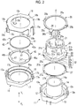
Fig. 2 is an exploded perspective view of the rotary type input device of the first embodiment. -
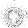
Fig. 3 is a cross sectional view taken along line III-III shown inFig. 1 . -
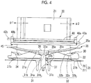
Fig. 4 is a front view showing a state where a rotary member is stabilized at a return rotation position and a housing is removed. -
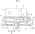
Fig. 5 is a front view showing a state where the rotary member rotates to an input rotation position, a follower is fitted to a holding recessed portion, and the housing is removed. -
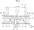
Fig. 6 is a front view showing a state where a hold release member moves to a hold release position, the fitting between the follower and the holding recessed portion is released, the rotary member is returned to the return rotation position, and the housing is removed. -
Fig. 7 is a vertical sectional view showing a rotary type input device of a second embodiment of the present invention. -
Fig. 8 is a perspective view showing the rotary type input device of the second embodiment in a state where an upper housing is removed. -
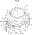
Fig. 9 is a perspective view showing a state where fitting between a follower and a holding recessed portion is released and the upper housing is removed in the rotary type input device of the second embodiment. - As shown in
Figs. 1 and2 , a rotarytype input device 1 of a first embodiment of the present invention includes ahousing 10. Thehousing 10 is configured of alower housing 11, anupper housing 15, and a holding metal fitting 18. Thelower housing 11 and theupper housing 15 are formed of synthetic resin materials, and theholding metal fitting 18 is formed of a metal plate material. - As shown in
Fig. 2 , thelower housing 11 includes anannular bottom portion 12, and a lowercircumferential wall portion 13 which integrally extends upward (Y1 direction) from the outer circumferential edge of thebottom portion 12. A rotary supportingportion 14 which extends upward (Y1 direction) from the inner circumferential edge of thebottom portion 12 is integrally formed. The rotary supportingportion 14 has a cylindrical shape, acylindrical hole 14a thereof is formed to penetrate thelower housing 11 in a vertical direction(Y1-Y2 direction), and as shown inFig. 1 , thecylindrical hole 14a is formed to penetrate vertically theentire housing 10. A center line which is positioned at the center of the rotary supportingportion 14 and extends vertically is a rotation center line O. - As shown in
Fig. 2 , theupper housing 15 includes apartition wall 16 which is formed in a plane orthogonal to the rotation center line O, and acircular opening portion 16a is formed in thepartition wall 16. An uppercircumferential wall portion 17 is integrally formed upward (Y1 direction) from the outer circumferential edge of thepartition wall 16. - As shown in
Fig. 1 , thelower housing 11 and theupper housing 15 vertically overlap each other, and are combined to be positioned to each other by recession/protrusion fitting or the like. The outer surfaces of the lowercircumferential wall portion 13 and the uppercircumferential wall portion 17 have the same shape as each other, and the outer surface of the lowercircumferential wall portion 13 is approximately coincident with the outer surface of the uppercircumferential wall portion 17 in a state where thelower housing 11 and theupper housing 15 are combined to each other. - The
holding metal fitting 18 includes acover plate portion 18a, and acircular opening portion 18b is formed in thecover plate portion 18a. The holding metal fitting 18 includes a pair offirst holding pieces 19a which is bent downward (Y2 direction) from the circumferential edge portion of thecover plate portion 18a, and multiplesecond holding pieces 19b. The pair offirst holding pieces 19a is fitted to holdinggrooves 17a which are formed on the outer surface of theupper housing 15, and is fitted to holdinggrooves 13a which are formed on the outer surface of thelower housing 11. The multiplesecond holding pieces 19b elastically press the outer surface of theupper housing 15 and the outer surface of thelower housing 11, andbent portions 19c positioned on the lower end thereof are locked to the lower surface of thelower housing 11. Thelower housing 11 and theupper housing 15 are elastically held by the holding metal fitting 18 to assemble thehousing 10. - As shown in
Fig. 1 , in the state where thehousing 10 is assembled, the inside of thehousing 10 is divided into a lower space S1 and an upper space S2 by thepartition wall 16 of theupper housing 15. The lower space S1 is surrounded by thebottom portion 12 and the lowercircumferential wall portion 13 of thelower housing 11, and thepartition wall 16. The upper space S2 is surrounded by thepartition wall 16 and the uppercircumferential wall portion 17 of theupper housing 15 and thecover plate portion 18a of the holdingmetal fitting 18. - A
rotary member 20 is accommodated inside thehousing 10. Therotary member 20 is formed of a synthetic resin material. As shown inFig. 2 , in therotary member 20, ashaft portion 21, and aflanged extension portion 22 which spreads in the circumferential direction from the lower portion of theshaft portion 21 are integrally formed. Theshaft portion 21 has a cylindrical shape, and ashaft hole 21a is formed to penetrate in the vertical direction (Y1-Y2 direction). - As shown in
Fig. 1 , theshaft hole 21a of therotary member 20 is inserted into the outer side of therotary supporting portion 14 of thelower housing 11. The upper portion of theshaft portion 21 of therotary member 20 passes through the inside of theopening portion 16a formed in thepartition wall 16 of theupper housing 15 and the inside of theopening portion 18b formed in thecover plate portion 18a of the holding metal fitting 18 to protrude upward, and therotary member 20 slides on the outer circumferential surface of therotary supporting portion 14 and can rotate about the rotation center line O. Theextension portion 22 of therotary member 20 is positioned inside the lower space S1 of thehousing 10, and alower surface 22a of theextension portion 22 is installed on aprotrusion portion 12a which is formed to have a higher step (Y1 direction) upward than thebottom portion 12 of thelower housing 11 on the inner surface of thebottom portion 12. - As shown in
Fig. 1 , a rotation detection space S3 is formed on the outer circumferential side of theprotrusion portion 12a, and arotation detection unit 25 is accommodated inside the rotation detection space S3. Therotation detection unit 25 is configured of a fixedcontact 26 and a slidingcontact 27. The fixedcontact 26 is fixed to thebottom portion 12 of thelower housing 11. The fixedcontact 26 is embedded to thelower housing 11 by a so-called insert molding method, and the contact portion of the fixedcontact 26 is exposed to the inner surface of thebottom portion 12. The contact portion is divided into multiple portions, andmultiple terminals 26a continuous from the divided contact portions protrude downward from thelower housing 11. - As shown in
Fig. 2 , the slidingcontact 27 is formed of a conductive metal plate having spring property, and in the slidingcontact 27, a fixedring portion 27a, andmultiple sliders 27b which are branched from the fixedring portion 27a and are bent downward (Y2 direction) are integrally formed. As shown inFig. 1 , the fixedring portion 27a is fixed to theextension portion 22 by caulkingmultiple fixation protrusions 28 which protrude from thelower surface 22a of theextension portion 22, and thesliders 27b can come into contact with the contact portion of the fixedcontact 26. - If the
rotary member 20 rotates around therotary supporting portion 14, contact states between thesliders 27b and the contact portion of the fixedcontact 26 are changed, and the state can be switched to electric detection state according to the rotation angle of therotary member 20. - As shown in
Fig. 2 , acam portion 30 is integrally formed with anextension surface 22b facing the top of theextension portion 22 of therotary member 20. Theextension surface 22b which is the upper surface of theextension portion 22 is a surface intersecting the rotation center line O. Thecam portion 30 includes a cam surface which faces upward (Y1 direction). The cam surface includes a return recessedportion 31, and includes a first holding recessedportion 32 and a second holding recessedportion 33 in this order in a α2 direction from the return recessedportion 31. A third holding recessedportion 34 is formed in a α1 direction from the return recessedportion 31. In addition, the lower surface of theextension portion 22 becomes an extension surface, and thecam portion 30 is formed on the lower surface. - As shown in
Figs. 2 and4 , the return recessedportion 31 is configured of abottom portion 31a, and inclinedportions bottom portion 31a in the rotation direction. The first holding recessedportion 32 is also configured of abottom portion 32a, and inclinedportions bottom portion 32a. Similarly, each of the second holding recessedportion 33 and the third holding recessedportion 34 is configured of a bottom portion and inclined portions which are continuous to be adjacent to both sides of the bottom portion. Moreover, a boundary portion between theinclined portion 31b of the return recessedportion 31 and theinclined portion 32b of the first holding recessedportion 32 is a protrusion portion. Similarly, a boundary portion between the first holding recessedportion 32 and the second holding recessedportion 33 also is a protrusion portion, and a boundary portion between the return recessedportion 31 and the third holding recessedportion 34 also is a protrusion portion. - As shown in
Fig. 1 , a holdingspring member 35 and afollower 36 which is fixed to the holdingspring member 35 are accommodated in the lower space S1 below thepartition wall 16 of thehousing 10. As shown inFig. 2 , the holdingspring member 35 is formed of a metal spring material and has a ring shape. In the holdingspring member 35, afixation portion 35a, and anelastic pressure portion 35c in which a portion of the ring is deformed downward (Y2 direction) are integrally formed. Attachment holes 35b are formed on thefixation portion 35a, and thefixation portion 35a is fixed to the lower surface 16b of thepartition wall 16 of theupper housing 15 by caulking fixation protrusion (not shown) integrally formed with theupper housing 15 to the attachment holes 35b. - The
follower 36 facing thecam portion 30 is fixed to the center portion of theelastic pressure portion 35c of the holdingspring member 35. Thefollower 36 is formed of a synthetic resin material, and in thefollower 36, a slidingprotrusion portion 36a which slides on thecam portion 30, and apressing portion 36b which further extends in the direction separated from the rotation center line O than the slidingprotrusion portion 36a and has a recessed portion facing downward are integrally formed. - As shown in
Figs. 1 and4 , thefollower 36 is biased in a downward direction which is the direction intersecting theextension surface 22b by an elastic force of theelastic pressure portion 35c of the holdingspring member 35, and thefollower 36 is pressed by thecam portion 30. In addition, thelower surface 22a of theextension portion 22 of therotary member 20 is pressed to theprotrusion portion 12a formed on thebottom portion 12 of thelower housing 11 by the elastic force of theelastic pressure portion 35c, and thus, rattling of therotary member 20 inside thehousing 10 in the direction along the rotation center line O is prevented. - As shown in
Fig. 1 , a pin-shaped (shaft-shaped) holdrelease member 37 is provided inside the lower space S1 of thehousing 10. A slidinghole 12b which penetrates vertically is formed on thebottom portion 12 of thelower housing 11, and thehold release member 37 is inserted into the slidinghole 12b and is slidingly supported in the vertical direction (Y1-Y2 direction) which is the direction (the direction parallel to the rotation center line O) intersecting theextension surface 22b. - As shown in
Figs. 1 and4 , when an external force is not applied to thehold release member 37, thepressing portion 36b of thefollower 36 presses ahead portion 37a of thehold release member 37 downward (Y2 direction) by the elastic force of the holdingspring member 35, and the posture becomes an initial posture in which thehold release member 37 is lowered in the slidinghole 12b. As shown inFig. 2 , astopper 37b is integrally formed on the upper portion of thehold release member 37, and when thehold release member 37 is lowered to the initial posture shown inFig. 1 , thestopper 37b comes into contact with the inner surface of thebottom portion 12 of thelower housing 11, and downward extraction of thehold release member 37 is prevented. When thehold release member 37 is in the initial posture, apressing operation portion 37c on the lower end portion of thehold release member 37 protrudes downward from thebottom portion 12 of thelower housing 10. - As shown in
Fig. 1 , a return spring member 4 0 and aspring support member 45 are accommodated inside the upper space S2 of thehousing 10. Thespring support member 45 is formed of a synthetic resin material and has a ring shape. Acircular opening portion 46 is formed in thespring support member 45, and as shown inFig. 1 , the openingportion 46 is inserted into the outer circumferential portion of theshaft portion 21 of therotary member 20.Engagement protrusions 47 protruding from three locations toward the openingportion 46 are integrally formed on thespring support member 45. Eachengagement protrusion 47 engages with anengagement groove 21b which is formed upward (Y1 direction) in theshaft portion 21 of therotary member 20, and thespring support member 45 can rotate along with therotary member 20. - As shown in
Fig. 2 , in thespring support member 45, a pair ofspring hook portions upper housing 15,spring support protrusions circumferential wall portion 17. - The
return spring member 40 is a torsion spring, and includes a windingmain body 41 around which a spring wire is wound, and lockingarm portions Fig. 3 , the windingmain body 41 of thereturn spring member 40 is installed on the outer circumferential portion of theshaft portion 21 of therotary member 20 inside the upper space S2. Onelocking arm portion 42a of thereturn spring member 40 is hooked to onespring hook portion 48a of thespring support member 45, and is hooked to thespring support protrusion 17b formed on theupper housing 15. The otherlocking arm portion 42b is hooked to the otherspring hook portion 48b and is hooked to thespring support protrusion 17c. - A force by which the
rotary member 20 is returned to the return rotation position shown inFig. 3 is always applied to therotary member 20 by the elastic force of thereturn spring member 40. - In an assembly operation of the rotary
type input device 1 having the above-described structure, theshaft hole 21a of therotary member 20 to which the slidingcontact 27 is fixed is inserted into therotary support portion 14 of thelower housing 11. In addition, thehold release member 37 is inserted into the slidinghole 12b, which is formed on thebottom portion 12 of thelower housing 11, from the top. - The
fixation portion 35a of the holdingspring member 35 is fixed to the lower surface 16b of thepartition wall 16 of theupper housing 15, and theupper housing 15 is positioned on thelower housing 11 so as to be overlapped with each other. At this time, thefollower 36 which is fixed to the holdingspring member 35 is pressed to thecam portion 30 of therotary member 20, and therotary member 20 is pressed downward. In addition, thehold release member 37 is pressed downward by thefollower 36. - The
shaft portion 21 of therotary member 20 protrudes upward from theopening portion 16a which is formed on thepartition wall 16 of theupper housing 15. Thespring support member 45 and thereturn spring member 40 are mounted on the outer circumference of theshaft portion 21 which protrudes upward from thepartition wall 16. Moreover, the holding metal fitting 18 is mounted from the top, and thelower housing 11 and theupper housing 15 are held by the holdingmetal fitting 18. At this time, theshaft portion 21 protrudes upward from theopening portion 18b which is formed in the holdingmetal fitting 18. - The rotary
type input device 1 is provided inside a compartment of an automobile, and is used for switching of a shift lever or switching operations of various electrical components. - As shown in
Fig. 1 , thecylindrical hole 14a of thelower housing 11 is formed to penetrate vertically along the rotation center line O in the rotarytype input device 1. If the rotary type input device is mounted on the compartment, an operation knob is fixed to the tip portion of theshaft portion 21 of therotary member 20. An illumination display portion such as characters or symbols is provided on the operation knob. In the mounting state, a light source is provided below thelower housing 11, light emitted from the light source passes through the inside of thecylinder hole 14a and is applied to the operation knob, and the display portion is illuminated. - Next, an operation of the rotary
type input device 1 will be described. - In
Fig. 3 , the elastic force of thereturn spring member 40 configured of a torsion spring is equally applied to therotary member 20 in the α1 direction and the α2 direction, and therotary member 20 is returned to the return rotation position by the elastic force of thereturn spring member 40. At this time, as shown inFig. 4 , the slidingprotrusion portion 36a of thefollower 36 is pressed to the return recessedportion 31 of thecam portion 30 formed on therotary member 20 by the elastic force of theelastic pressure portion 35c of the holdingspring member 35. As a result, therotary member 20 is held at the return rotation position. - When the
rotary member 20 is returned to the return rotation position (neutral position) by thereturn spring member 40, even though the center of thefollower 36 and thebottom portion 31a of the return recessedportion 31 of thecam portion 30 do not correctly coincide with each other, if thefollower 36 faces theinclined portions 31b positioned on both sides of thebottom portion 31a, the slidingprotrusion portion 36a of thefollower 36 which is pressed into the return recessedportion 31 by the elastic force of the holdingspring member 35 is introduced from theinclined portion 31b to thebottom portion 31a. As a result, as shown inFig. 4 , the state is transferred to a state where the slidingprotrusion portion 36a comes into pressure-contact with thebottom portion 31a, and therotary member 20 is stabilized at the return rotation position. - When the
rotary member 20 is positioned at the return rotation position, a switching output of the contact corresponding to the return rotation position is obtained from the terminal 26a according to the contact state between the slidingcontact 27 fixed to therotary member 20 and the fixedcontact 26 fixed to thelower housing 11. -
Fig. 5 shows a state where therotary member 20 positioned at the return rotation position rotates in the α1 direction and reaches a first input rotation position. In the first input rotation position, the first holding recessedportion 32 of thecam portion 30 formed in therotary member 20 moves below thefollower 36, thefollower 36 is pressed to thecam portion 30 by the elastic force of the holdingspring member 35, and the slidingprotrusion portion 36a of thefollower 36 is fitted into thebottom portion 32a of the first holding recessedportion 32. At this time, therotary member 20 is stabilized at the first input rotation position shown inFig. 5 regardless of a return elastic force generated by thereturn spring member 40. - If the
rotary member 20 further rotates in the α1 direction from the first input rotation position ofFig. 5 , the second holding recessedportion 33 of therotary member 20 is fitted to thefollower 36, and therotary member 20 is held at a second input rotation position. - Meanwhile, if the
rotary member 20 rotates in the α2 direction from the return rotation position shown inFig. 4 , the third holding recessedportion 34 provided in therotary member 20 moves below thefollower 36, and the slidingprotrusion portion 36a of thefollower 36 is fitted to the bottom portion of the third holding recessedportion 34. Accordingly, therotary member 20 is held at the third input rotation position. - When the
rotary member 20 is positioned at the first input rotation position, the second input rotation position, or the third input rotation position, the switching output of the contact corresponding to each input rotation position is obtained from the terminal 26a according to the contact state between the slidingcontact 27 and the fixedcontact 26. - When the
rotary member 20 is positioned at the first input rotation position, the second input rotation position, or the third input rotation position, a return force is applied from thereturn spring member 40 to therotary member 20. However, a resistance force generated from the contact force between thefollower 36 and the holding recessedportions cam portion 30 by the holdingspring member 35 is set to be stronger than the return force. Accordingly, it is possible to stabilize therotary member 20 at each of input position/rotation positions. - As shown in
Figs. 1 ,4 , and5 , when the slidingprotrusion portion 36a of thefollower 36 is fitted to the first holding recessedportion 32, the second holding recessedportion 33, or the third holding recessedportion 34 of thecam portion 30, the posture becomes the initial posture in which thehold release member 37 is pressed downward by the elastic force of the holdingspring member 35, and thepressing operation 37c positioned on the lower end of thehold release member 37 protrude downward from the lower surface of thelower housing 11. - When the sliding
protrusion portion 36a of thefollower 36 is fitted to the first holding recessedportion 32, the second holding recessedportion 33 , or the third holding recessedportion 34 of thecam portion 30, if thepressing operation 37c of thehold release member 37 is pushed upward, the rotarytype input device 1 is returned to the initial state. Thepressing operation portion 37c is pushed upward by an operation mechanism having a solenoid or the like, or is manually pushed upward. - As shown in
Fig. 6 , if thehold release member 37 is pushed upward and reaches the hold release posture, thefollower 36 is pushed upward by thehead portion 37a of thehold release member 37, and the fitting between thefollower 36 and thecam portion 30 is released. As a result, therotary member 20 receives an elastic return force by thereturn spring member 40, and is returned to the return rotation position shown inFig. 4 . - In the rotary
type input device 1, thehold release member 37 which release the fitting between thefollower 36 and thecam portion 30 is lowered to reach the initial posture as shown inFig. 4 or5 by the holdingspring member 35. Since thefollower 36 is pressed to thecam portion 30 by the holdingspring member 35 and thehold release member 37 is biased to the initial posture by the holdingspring member 35, it is possible to reduce the number of springs, simplify the structure, and reduce a manufacturing cost. - In addition, since the
follower 36 is directly pushed by thehold release member 37, it is possible to reliably release the fitting between thefollower 36 and thecam portion 30, and after the fitting is released, it possible to reliably return therotary member 20 to the return rotation position shown inFig. 4 . Moreover, in the present invention, the holdingspring member 35 may be pushed by thehold release member 37 to release the fitting between thefollower 36 and thecam portion 30. - In the rotary
type input device 1 of the first embodiment, since thecam portion 30 is formed on oneextension surface 22b of theflanged extension portion 22 formed in therotary member 20 and the slidingcontact 27 is fixed to the otherlower surface 22a, the rotarytype input device 1 can be conf igured of the minimum number of components, and it is possible to decrease the size of the entire structure. - In addition, the inside of the
housing 10 is divided by thepartition wall 16, a holding mechanism including the holdingspring member 35, thefollower 36, and thehold release member 37 is disposed in one space S1, and a return mechanism including thereturn spring member 40 is disposed in the other space S2. Since a movable mechanism using springs is disposed in the space divided by thepartition wall 16, the holdingspring member 35 and thereturn spring member 40 do not come into contact with each other so as not to interfere with each other, and it is possible to reliably operate each mechanism. -
Figs. 7 to 9 show a rotarytype input device 101 of a second embodiment of the present invention. The structure of the rotarytype input device 101 of the second embodiment is different from the structure of the rotarytype input device 1 of the first embodiment. However, hereinafter, the same names and the same reference numerals are assigned to the portions having the same functions as those of the rotarytype input device 1 of the first embodiment. - As shown in
Fig. 7 , thehousing 10 is configured of thelower housing 11, theupper housing 15, thepartition wall 16, and the holdingmetal fitting 18. In the rotarytype input device 101 of the second embodiment, thelower housing 11, theupper housing 15, and thepartition wall 16 are configured of parts independent from each other. Therotary supporting portion 14 is formed in thelower housing 11, and theshaft hole 21a of theshaft portion 21 of therotary member 20 is rotatably mounted on the outer circumferential portion of therotary supporting portion 14. - The inside of the
housing 10 is divided into a lower space Sa and an upper space Sb by thepartition wall 16. Thespring support member 45 and thereturn spring member 40 configured of a torsion spring are accommodated in the lower space Sa. Thespring support member 45 is fitted to therotary member 20 and rotates along with therotary member 20. Similarly to the first embodiment, therotary member 20 is returned to the return rotation position (neutral position) by thereturn spring member 40. - The
extension portion 22 extending from the outer circumferential portion of therotary member 20 is positioned inside the upper space Sb. Therotation detection unit 25 is configured between thelower surface 22a of theextension portion 22 and thepartition wall 16. The fixedcontact 26 configuring therotation detection unit 25 is fixed to thepartition wall 16, and the slidingcontact 27 is fixed tolower surface 22a of theextension portion 22. - As shown in
Figs. 8 and9 , thecam portion 30 is formed on the outer circumferential end of theflanged extension portion 22 formed on therotary member 20. Thecam portion 30 includes the return recessedportion 31, the first holding recessedportion 32, the second holding recessedportion 33, and the third holding recessedportion 34. The recessed portion of thecam portion 30 is recessed in the direction toward the rotation center line O, and the protrusion portion protrudes from the rotation center line O toward the outside in the radial direction. - As shown in
Fig. 7 , thefollower 36 is provided in the upper space Sb of thehousing 10. A slidingshaft 36d which protrudes upward is integrally formed on thefollower 36, the slidingshaft 36d is inserted into along guide hole 15b which is formed on atop plate portion 15a of theupper housing 15, and thefollower 36 is guided to be movable in a β1-β2 direction. The β1-β2 direction is a radial direction (radiation direction) with the rotation center line O as a center, that is, a direction which approaches or is separated from the rotation center line O. If thefollower 36 moves in the β1 direction, a slidingprotrusion portion 36e formed on thefollower 36 is fitted to the recessed portion of thecam portion 30. - The holding
spring member 35 is accommodated in the upper space Sb of thehousing 10. The holdingspring member 35 is formed of a metal leaf spring material. As shown inFig. 8 ,fixation portions spring member 35 are supported by thepartition wall 16 or theupper housing 15, and thefollower 36 is biased in the β1 direction by an intermediateelastic pressure portion 35e. The slidingprotrusion portion 36e of thefollower 36 comes into pressure-contact with thecam portion 30 by the elastic force. - The
hold release member 37 is accommodated in the upper space Sb of thehousing 10. As shown inFigs. 8 and9 , thehold release member 37 has a curved shape along an arc and is positioned on the outer circumference of theshaft portion 21 of therotary member 20. Anupward support shaft 37d is integrally formed in the center portion of thehold release member 37, thesupport shaft 37d is inserted into a support hole (not shown) of thetop plate portion 15a of theupper housing 15, and thehold release member 37 is supported so as to be rotatable (swingable) in a φ1-φ2 direction in a plane intersecting (orthogonal to) the rotation center line O. - One end of the
hold release member 37 is ahold release portion 37e, and a connection recessedportion 37f which is formed on thehold release portion 37e is connected to the slidingshaft 36d of thefollower 36. Apressing operation portion 37g is formed on the other end of thehold release member 37, and thepressing operation portion 37g protrudes toward the outside of thehousing 10. - In the rotary
type input device 101, therotary member 20 is returned to the return rotation position shown inFig. 8 by the elastic force of thereturn spring member 40. At this time, thefollower 36 is biased in the β1 direction by theelastic pressure portion 35e of the holdingspring member 35, and the slidingprotrusion portion 36e of thefollower 36 is fitted to the return recessedportion 31 of thecam portion 30. - If the
rotary member 20 rotates in the α1 direction, the slidingprotrusion portion 36e of thefollower 36 is fitted to the first holding recessedportion 32 of thecam portion 30, and therotary member 20 is head at the first input rotation position. If therotary member 20 further rotates in the α1 direction, the slidingprotrusion portion 36e of thefollower 36 is fitted to the second holding recessedportion 33 of thecam portion 30, and therotary member 20 is held at the second input rotation position. If therotary member 20 rotates in the α2 direction from the return rotation position ofFig. 8 , the slidingprotrusion portion 36e of thefollower 36 is fitted to the third holding recessedportion 34 of thecam portion 30, and therotary member 20 is held at the third input rotation position. - When the sliding
protrusion portion 36e of thefollower 36 is fitted to the return recessedportion 31 of thecam portion 30 or each of the holding recessedportions Fig. 8 , the slidingshaft 36d of thefollower 36 rotates in the φ1 direction to reach the initial posture. - When the sliding
protrusion portion 36e of thefollower 36 is fitted to any one of the holding recessedportions cam portion 30 and therotary member 20 is held at any one of the input rotation positions, if thepressing operation portion 37g of thehold release member 37 is pushed by an operation mechanism having a solenoid or the like or manually, as shown inFig. 9 , thehold release member 37 rotates in the φ2 direction with thesupport shaft 37d as a center to reach the hold release posture, thefollower 36 moves in the β2 direction, fitting between the slidingprotrusion portion 36e of thefollower 36 and any one of the holding recessedportions cam portion 30 is released, and therotary member 20 is returned to the return rotation position shown inFig. 8 by the biasing force of thereturn spring member 40. - In the rotary
type input device 101 of the second embodiment, since both thefollower 36 and thehold release member 37 are biased by the holdingspring member 35, it is possible to reduce the number of springs. In addition, since thefollower 36 is directly moved by thehold release member 37, it is possible to reliably release the fitting between thefollower 36 and the holding recessedportions -
- 1, 101:
- rotary type input device
- 10:
- housing
- 14:
- rotary supporting portion
- 16:
- partition wall
- 20:
- rotary member
- 21:
- shaft portion
- 21a:
- shaft hole
- 22:
- extension portion
- 22b:
- extension surface
- 25:
- rotation detection unit
- 26:
- fixed contact
- 27:
- sliding contact
- 30:
- cam portion
- 31:
- return recessed portion
- 31a:
- bottom portion
- 31b:
- inclined portion
- 32, 33, 34:
- holding recessed portion
- 35:
- holding spring member
- 36:
- follower
- 37:
- hold release member
- 40:
- return spring member
- 45:
- spring support member
- O:
- rotation center line
- S1:
- lower space
- S2:
- upper space
- Sa:
- lower space
- Sb:
- upper space
Claims (12)
- A rotary type input device comprising:a housing;a rotary member which is rotatably supported by the housing and is rotatable from a return rotation position to an input rotation position; anda rotation detection unit which changes a detection state according to the rotation of the rotary member,wherein a cam portion which is formed in the rotary member, a follower which faces the cam portion, and a holding spring member which presses the follower to the cam portion are provided, and a holding recessed portion which is fitted to the follower to hold the rotary member when the rotary member rotates to the input rotation position is formed in the cam portion,
wherein a hold release member which releases the fitting between the follower and the holding recessed portion, and a return spring member which returns the rotary member to the return rotation position when the fitting is released are provided, and
wherein the hold release member is provided to be movable from an initial posture to a hold release posture at which the fitting is released, and is returned to the initial posture by the holding spring member. - The rotary type input device according to claim 1,
wherein the follower or the holding spring member is pushed by the hold release member when the hold release member moves to the hold release posture, and the fitting between the follower and the holding recessed portion is released. - The rotary type input device according to claim 1 or 2,
wherein a return recessed portion is formed in the cam portion, the follower faces a bottom portion of the return recessed portion or an inclined portion adjacent to the bottom portion when the rotary member is returned to the return rotation position by return spring member, and the follower is fitted to the return recessed portion by a biasing force of the holding spring member. - The rotary type input device according to any one of claims 1 to 3,
wherein the return spring member is set such that a fitting force between the follower and the holding recessed portion is stronger than a force which returns the rotary member positioned at the input rotation position to the return rotation position. - The rotary type input device according to any one of claims 1 to 4,
wherein a shaft portion which extends along a rotation center line and an extension portion which extends in a circumferential direction from the shaft portion are integrally formed with each other in the rotary member, and the cam portion is formed on the extension portion. - The rotary type input device according to claim 5,
wherein the cam portion is formed on an extension surface side which is an upper surface or a lower surface of the extension portion, and the follower is biased in a direction intersecting the extension surface by the holding spring member, and is pressed to the cam portion. - The rotary type input device according to claim 6,
wherein the hold release member is supported to be movable forward and backward in the direction intersecting the extension surface. - The rotary type input device according to claim 5,
wherein the cam portion is formed along a circumferential end of the extension portion, and the follower is biased toward the rotation center line by the holding spring member and is pressed to the cam portion. - The rotary type input device according to claim 8,
wherein the hold release member is rotatably supported in a plane intersecting the rotation center line. - The rotary type input device according to any one of claims 5 to 9,
wherein the rotation detection unit includes a fixed contact and a sliding contact which slides on the fixed contact, the fixed contact is fixed to the housing, and the sliding contact is fixed to the extension portion. - The rotary type input device according to any one of claims 5 to 10,
wherein a shaft hole which extends along the rotation center line is formed in the shaft portion, a cylindrical rotary support portion is formed in the housing, and the shaft hole is rotatably supported on an outer circumferential surface of the rotary supporting portion. - The rotary type input device according to any one of claims 1 to 11,
wherein the inside of the housing is partitioned by a partition wall, the cam portion, the follower, the holding spring member, and the hold release member are provided in one space partitioned off by the partition wall, and the return spring member is provided in the other space.
Applications Claiming Priority (2)
| Application Number | Priority Date | Filing Date | Title |
|---|---|---|---|
| JP2014050237 | 2014-03-13 | ||
| PCT/JP2015/054739 WO2015137086A1 (en) | 2014-03-13 | 2015-02-20 | Rotating input device |
Publications (3)
| Publication Number | Publication Date |
|---|---|
| EP3133629A1 true EP3133629A1 (en) | 2017-02-22 |
| EP3133629A4 EP3133629A4 (en) | 2018-03-07 |
| EP3133629B1 EP3133629B1 (en) | 2018-12-05 |
Family
ID=54071535
Family Applications (1)
| Application Number | Title | Priority Date | Filing Date |
|---|---|---|---|
| EP15761544.4A Not-in-force EP3133629B1 (en) | 2014-03-13 | 2015-02-20 | Rotating input device |
Country Status (2)
| Country | Link |
|---|---|
| EP (1) | EP3133629B1 (en) |
| WO (1) | WO2015137086A1 (en) |
Family Cites Families (5)
| Publication number | Priority date | Publication date | Assignee | Title |
|---|---|---|---|---|
| JPS5959430U (en) * | 1981-12-23 | 1984-04-18 | 帝国通信工業株式会社 | Small automatic center return rotary switch |
| JPS59111212A (en) * | 1982-12-15 | 1984-06-27 | アルプス電気株式会社 | Rotating electrical parts |
| JPH0433234U (en) * | 1990-07-16 | 1992-03-18 | ||
| JP2564057Y2 (en) * | 1993-08-18 | 1998-03-04 | ホシデン株式会社 | Rotary switch |
| EP2594423B1 (en) * | 2011-11-21 | 2014-11-05 | Valeo Autoklimatizace k.s. | Control device |
-
2015
- 2015-02-20 WO PCT/JP2015/054739 patent/WO2015137086A1/en not_active Ceased
- 2015-02-20 EP EP15761544.4A patent/EP3133629B1/en not_active Not-in-force
Also Published As
| Publication number | Publication date |
|---|---|
| EP3133629B1 (en) | 2018-12-05 |
| WO2015137086A1 (en) | 2015-09-17 |
| EP3133629A4 (en) | 2018-03-07 |
Similar Documents
| Publication | Publication Date | Title |
|---|---|---|
| EP3107110B1 (en) | Contact mechanism, trigger switch using contact mechanism, and electric tool | |
| KR102051153B1 (en) | Push switch | |
| WO2016132697A1 (en) | Push switch | |
| US9012797B2 (en) | Vehicular lever switch and method of assembling same | |
| JP5117339B2 (en) | Compound operation type input device | |
| EP3709331A1 (en) | Input device | |
| JP4832317B2 (en) | Combined operation type input device | |
| EP2793245B1 (en) | Push switch | |
| EP3133629B1 (en) | Rotating input device | |
| EP2757567B1 (en) | Push button switch | |
| EP2743951B1 (en) | Push-switch | |
| EP2628637A2 (en) | In-vehicle lever switch device | |
| JP6410571B2 (en) | Switch device | |
| EP3128527A1 (en) | Switch device | |
| JP2010282750A (en) | Rotary electric component | |
| JP5819130B2 (en) | Rotating electrical parts | |
| KR100990057B1 (en) | Rotary electrical parts | |
| JP2005123021A (en) | Composite switch unit | |
| JP6601770B2 (en) | Switch device and vehicle equipped with the same | |
| KR100340483B1 (en) | Variable resistor | |
| JP4619196B2 (en) | Sliding electronic parts with pressure switch | |
| JP2007179882A (en) | Rotary type electric parts | |
| EP2315224A2 (en) | Operating panel body | |
| JP2022042411A (en) | Rotary operation type electronic component | |
| JP2021093279A (en) | Operation device |
Legal Events
| Date | Code | Title | Description |
|---|---|---|---|
| STAA | Information on the status of an ep patent application or granted ep patent |
Free format text: STATUS: THE INTERNATIONAL PUBLICATION HAS BEEN MADE |
|
| PUAI | Public reference made under article 153(3) epc to a published international application that has entered the european phase |
Free format text: ORIGINAL CODE: 0009012 |
|
| STAA | Information on the status of an ep patent application or granted ep patent |
Free format text: STATUS: REQUEST FOR EXAMINATION WAS MADE |
|
| 17P | Request for examination filed |
Effective date: 20161201 |
|
| AK | Designated contracting states |
Kind code of ref document: A1 Designated state(s): AL AT BE BG CH CY CZ DE DK EE ES FI FR GB GR HR HU IE IS IT LI LT LU LV MC MK MT NL NO PL PT RO RS SE SI SK SM TR |
|
| AX | Request for extension of the european patent |
Extension state: BA ME |
|
| DAX | Request for extension of the european patent (deleted) | ||
| A4 | Supplementary search report drawn up and despatched |
Effective date: 20180202 |
|
| RIC1 | Information provided on ipc code assigned before grant |
Ipc: H01H 19/20 20060101AFI20180129BHEP |
|
| GRAP | Despatch of communication of intention to grant a patent |
Free format text: ORIGINAL CODE: EPIDOSNIGR1 |
|
| STAA | Information on the status of an ep patent application or granted ep patent |
Free format text: STATUS: GRANT OF PATENT IS INTENDED |
|
| INTG | Intention to grant announced |
Effective date: 20180626 |
|
| GRAS | Grant fee paid |
Free format text: ORIGINAL CODE: EPIDOSNIGR3 |
|
| GRAA | (expected) grant |
Free format text: ORIGINAL CODE: 0009210 |
|
| STAA | Information on the status of an ep patent application or granted ep patent |
Free format text: STATUS: THE PATENT HAS BEEN GRANTED |
|
| AK | Designated contracting states |
Kind code of ref document: B1 Designated state(s): AL AT BE BG CH CY CZ DE DK EE ES FI FR GB GR HR HU IE IS IT LI LT LU LV MC MK MT NL NO PL PT RO RS SE SI SK SM TR |
|
| REG | Reference to a national code |
Ref country code: GB Ref legal event code: FG4D |
|
| REG | Reference to a national code |
Ref country code: CH Ref legal event code: EP |
|
| REG | Reference to a national code |
Ref country code: AT Ref legal event code: REF Ref document number: 1074092 Country of ref document: AT Kind code of ref document: T Effective date: 20181215 |
|
| REG | Reference to a national code |
Ref country code: IE Ref legal event code: FG4D |
|
| REG | Reference to a national code |
Ref country code: DE Ref legal event code: R096 Ref document number: 602015020972 Country of ref document: DE |
|
| REG | Reference to a national code |
Ref country code: DE Ref legal event code: R081 Ref document number: 602015020972 Country of ref document: DE Owner name: ALPS ALPINE CO., LTD., JP Free format text: FORMER OWNER: ALPS ELECTRIC CO., LTD, TOKYO, JP |
|
| REG | Reference to a national code |
Ref country code: NL Ref legal event code: MP Effective date: 20181205 |
|
| REG | Reference to a national code |
Ref country code: AT Ref legal event code: MK05 Ref document number: 1074092 Country of ref document: AT Kind code of ref document: T Effective date: 20181205 |
|
| REG | Reference to a national code |
Ref country code: LT Ref legal event code: MG4D |
|
| PG25 | Lapsed in a contracting state [announced via postgrant information from national office to epo] |
Ref country code: FI Free format text: LAPSE BECAUSE OF FAILURE TO SUBMIT A TRANSLATION OF THE DESCRIPTION OR TO PAY THE FEE WITHIN THE PRESCRIBED TIME-LIMIT Effective date: 20181205 Ref country code: LV Free format text: LAPSE BECAUSE OF FAILURE TO SUBMIT A TRANSLATION OF THE DESCRIPTION OR TO PAY THE FEE WITHIN THE PRESCRIBED TIME-LIMIT Effective date: 20181205 Ref country code: HR Free format text: LAPSE BECAUSE OF FAILURE TO SUBMIT A TRANSLATION OF THE DESCRIPTION OR TO PAY THE FEE WITHIN THE PRESCRIBED TIME-LIMIT Effective date: 20181205 Ref country code: AT Free format text: LAPSE BECAUSE OF FAILURE TO SUBMIT A TRANSLATION OF THE DESCRIPTION OR TO PAY THE FEE WITHIN THE PRESCRIBED TIME-LIMIT Effective date: 20181205 Ref country code: NO Free format text: LAPSE BECAUSE OF FAILURE TO SUBMIT A TRANSLATION OF THE DESCRIPTION OR TO PAY THE FEE WITHIN THE PRESCRIBED TIME-LIMIT Effective date: 20190305 Ref country code: LT Free format text: LAPSE BECAUSE OF FAILURE TO SUBMIT A TRANSLATION OF THE DESCRIPTION OR TO PAY THE FEE WITHIN THE PRESCRIBED TIME-LIMIT Effective date: 20181205 Ref country code: BG Free format text: LAPSE BECAUSE OF FAILURE TO SUBMIT A TRANSLATION OF THE DESCRIPTION OR TO PAY THE FEE WITHIN THE PRESCRIBED TIME-LIMIT Effective date: 20190305 Ref country code: ES Free format text: LAPSE BECAUSE OF FAILURE TO SUBMIT A TRANSLATION OF THE DESCRIPTION OR TO PAY THE FEE WITHIN THE PRESCRIBED TIME-LIMIT Effective date: 20181205 |
|
| PG25 | Lapsed in a contracting state [announced via postgrant information from national office to epo] |
Ref country code: GR Free format text: LAPSE BECAUSE OF FAILURE TO SUBMIT A TRANSLATION OF THE DESCRIPTION OR TO PAY THE FEE WITHIN THE PRESCRIBED TIME-LIMIT Effective date: 20190306 Ref country code: RS Free format text: LAPSE BECAUSE OF FAILURE TO SUBMIT A TRANSLATION OF THE DESCRIPTION OR TO PAY THE FEE WITHIN THE PRESCRIBED TIME-LIMIT Effective date: 20181205 Ref country code: SE Free format text: LAPSE BECAUSE OF FAILURE TO SUBMIT A TRANSLATION OF THE DESCRIPTION OR TO PAY THE FEE WITHIN THE PRESCRIBED TIME-LIMIT Effective date: 20181205 Ref country code: AL Free format text: LAPSE BECAUSE OF FAILURE TO SUBMIT A TRANSLATION OF THE DESCRIPTION OR TO PAY THE FEE WITHIN THE PRESCRIBED TIME-LIMIT Effective date: 20181205 |
|
| PG25 | Lapsed in a contracting state [announced via postgrant information from national office to epo] |
Ref country code: NL Free format text: LAPSE BECAUSE OF FAILURE TO SUBMIT A TRANSLATION OF THE DESCRIPTION OR TO PAY THE FEE WITHIN THE PRESCRIBED TIME-LIMIT Effective date: 20181205 |
|
| PG25 | Lapsed in a contracting state [announced via postgrant information from national office to epo] |
Ref country code: IT Free format text: LAPSE BECAUSE OF FAILURE TO SUBMIT A TRANSLATION OF THE DESCRIPTION OR TO PAY THE FEE WITHIN THE PRESCRIBED TIME-LIMIT Effective date: 20181205 Ref country code: PT Free format text: LAPSE BECAUSE OF FAILURE TO SUBMIT A TRANSLATION OF THE DESCRIPTION OR TO PAY THE FEE WITHIN THE PRESCRIBED TIME-LIMIT Effective date: 20190405 Ref country code: CZ Free format text: LAPSE BECAUSE OF FAILURE TO SUBMIT A TRANSLATION OF THE DESCRIPTION OR TO PAY THE FEE WITHIN THE PRESCRIBED TIME-LIMIT Effective date: 20181205 Ref country code: PL Free format text: LAPSE BECAUSE OF FAILURE TO SUBMIT A TRANSLATION OF THE DESCRIPTION OR TO PAY THE FEE WITHIN THE PRESCRIBED TIME-LIMIT Effective date: 20181205 |
|
| PG25 | Lapsed in a contracting state [announced via postgrant information from national office to epo] |
Ref country code: EE Free format text: LAPSE BECAUSE OF FAILURE TO SUBMIT A TRANSLATION OF THE DESCRIPTION OR TO PAY THE FEE WITHIN THE PRESCRIBED TIME-LIMIT Effective date: 20181205 Ref country code: SM Free format text: LAPSE BECAUSE OF FAILURE TO SUBMIT A TRANSLATION OF THE DESCRIPTION OR TO PAY THE FEE WITHIN THE PRESCRIBED TIME-LIMIT Effective date: 20181205 Ref country code: RO Free format text: LAPSE BECAUSE OF FAILURE TO SUBMIT A TRANSLATION OF THE DESCRIPTION OR TO PAY THE FEE WITHIN THE PRESCRIBED TIME-LIMIT Effective date: 20181205 Ref country code: SK Free format text: LAPSE BECAUSE OF FAILURE TO SUBMIT A TRANSLATION OF THE DESCRIPTION OR TO PAY THE FEE WITHIN THE PRESCRIBED TIME-LIMIT Effective date: 20181205 Ref country code: IS Free format text: LAPSE BECAUSE OF FAILURE TO SUBMIT A TRANSLATION OF THE DESCRIPTION OR TO PAY THE FEE WITHIN THE PRESCRIBED TIME-LIMIT Effective date: 20190405 |
|
| REG | Reference to a national code |
Ref country code: DE Ref legal event code: R097 Ref document number: 602015020972 Country of ref document: DE |
|
| REG | Reference to a national code |
Ref country code: CH Ref legal event code: PL |
|
| PLBE | No opposition filed within time limit |
Free format text: ORIGINAL CODE: 0009261 |
|
| STAA | Information on the status of an ep patent application or granted ep patent |
Free format text: STATUS: NO OPPOSITION FILED WITHIN TIME LIMIT |
|
| PG25 | Lapsed in a contracting state [announced via postgrant information from national office to epo] |
Ref country code: LU Free format text: LAPSE BECAUSE OF NON-PAYMENT OF DUE FEES Effective date: 20190220 Ref country code: DK Free format text: LAPSE BECAUSE OF FAILURE TO SUBMIT A TRANSLATION OF THE DESCRIPTION OR TO PAY THE FEE WITHIN THE PRESCRIBED TIME-LIMIT Effective date: 20181205 Ref country code: MC Free format text: LAPSE BECAUSE OF FAILURE TO SUBMIT A TRANSLATION OF THE DESCRIPTION OR TO PAY THE FEE WITHIN THE PRESCRIBED TIME-LIMIT Effective date: 20181205 Ref country code: SI Free format text: LAPSE BECAUSE OF FAILURE TO SUBMIT A TRANSLATION OF THE DESCRIPTION OR TO PAY THE FEE WITHIN THE PRESCRIBED TIME-LIMIT Effective date: 20181205 |
|
| 26N | No opposition filed |
Effective date: 20190906 |
|
| REG | Reference to a national code |
Ref country code: BE Ref legal event code: MM Effective date: 20190228 |
|
| GBPC | Gb: european patent ceased through non-payment of renewal fee |
Effective date: 20190305 |
|
| REG | Reference to a national code |
Ref country code: IE Ref legal event code: MM4A |
|
| PG25 | Lapsed in a contracting state [announced via postgrant information from national office to epo] |
Ref country code: CH Free format text: LAPSE BECAUSE OF NON-PAYMENT OF DUE FEES Effective date: 20190228 Ref country code: LI Free format text: LAPSE BECAUSE OF NON-PAYMENT OF DUE FEES Effective date: 20190228 |
|
| PG25 | Lapsed in a contracting state [announced via postgrant information from national office to epo] |
Ref country code: GB Free format text: LAPSE BECAUSE OF NON-PAYMENT OF DUE FEES Effective date: 20190305 Ref country code: IE Free format text: LAPSE BECAUSE OF NON-PAYMENT OF DUE FEES Effective date: 20190220 |
|
| PG25 | Lapsed in a contracting state [announced via postgrant information from national office to epo] |
Ref country code: FR Free format text: LAPSE BECAUSE OF NON-PAYMENT OF DUE FEES Effective date: 20190228 Ref country code: BE Free format text: LAPSE BECAUSE OF NON-PAYMENT OF DUE FEES Effective date: 20190228 |
|
| PG25 | Lapsed in a contracting state [announced via postgrant information from national office to epo] |
Ref country code: TR Free format text: LAPSE BECAUSE OF FAILURE TO SUBMIT A TRANSLATION OF THE DESCRIPTION OR TO PAY THE FEE WITHIN THE PRESCRIBED TIME-LIMIT Effective date: 20181205 |
|
| PG25 | Lapsed in a contracting state [announced via postgrant information from national office to epo] |
Ref country code: MT Free format text: LAPSE BECAUSE OF NON-PAYMENT OF DUE FEES Effective date: 20190220 |
|
| PG25 | Lapsed in a contracting state [announced via postgrant information from national office to epo] |
Ref country code: CY Free format text: LAPSE BECAUSE OF FAILURE TO SUBMIT A TRANSLATION OF THE DESCRIPTION OR TO PAY THE FEE WITHIN THE PRESCRIBED TIME-LIMIT Effective date: 20181205 |
|
| PG25 | Lapsed in a contracting state [announced via postgrant information from national office to epo] |
Ref country code: HU Free format text: LAPSE BECAUSE OF FAILURE TO SUBMIT A TRANSLATION OF THE DESCRIPTION OR TO PAY THE FEE WITHIN THE PRESCRIBED TIME-LIMIT; INVALID AB INITIO Effective date: 20150220 |
|
| PG25 | Lapsed in a contracting state [announced via postgrant information from national office to epo] |
Ref country code: MK Free format text: LAPSE BECAUSE OF FAILURE TO SUBMIT A TRANSLATION OF THE DESCRIPTION OR TO PAY THE FEE WITHIN THE PRESCRIBED TIME-LIMIT Effective date: 20181205 |
|
| PGFP | Annual fee paid to national office [announced via postgrant information from national office to epo] |
Ref country code: DE Payment date: 20240219 Year of fee payment: 10 |
|
| REG | Reference to a national code |
Ref country code: DE Ref legal event code: R119 Ref document number: 602015020972 Country of ref document: DE |
|
| PG25 | Lapsed in a contracting state [announced via postgrant information from national office to epo] |
Ref country code: DE Free format text: LAPSE BECAUSE OF NON-PAYMENT OF DUE FEES Effective date: 20250902 |