EP3133628A1 - Appareil d'entrée - Google Patents
Appareil d'entrée Download PDFInfo
- Publication number
- EP3133628A1 EP3133628A1 EP15780137.4A EP15780137A EP3133628A1 EP 3133628 A1 EP3133628 A1 EP 3133628A1 EP 15780137 A EP15780137 A EP 15780137A EP 3133628 A1 EP3133628 A1 EP 3133628A1
- Authority
- EP
- European Patent Office
- Prior art keywords
- spacer
- rotating cam
- rotating
- pressing
- pressing part
- Prior art date
- Legal status (The legal status is an assumption and is not a legal conclusion. Google has not performed a legal analysis and makes no representation as to the accuracy of the status listed.)
- Granted
Links
- 125000006850 spacer group Chemical group 0.000 claims abstract description 62
- 230000007246 mechanism Effects 0.000 claims description 28
- 238000001514 detection method Methods 0.000 claims description 9
- 230000002093 peripheral effect Effects 0.000 claims description 8
- 238000006243 chemical reaction Methods 0.000 description 13
- 238000006073 displacement reaction Methods 0.000 description 3
- 239000013013 elastic material Substances 0.000 description 2
- 230000002441 reversible effect Effects 0.000 description 1
Images


Classifications
-
- H—ELECTRICITY
- H01—ELECTRIC ELEMENTS
- H01H—ELECTRIC SWITCHES; RELAYS; SELECTORS; EMERGENCY PROTECTIVE DEVICES
- H01H13/00—Switches having rectilinearly-movable operating part or parts adapted for pushing or pulling in one direction only, e.g. push-button switch
- H01H13/02—Details
- H01H13/12—Movable parts; Contacts mounted thereon
- H01H13/20—Driving mechanisms
-
- H—ELECTRICITY
- H01—ELECTRIC ELEMENTS
- H01H—ELECTRIC SWITCHES; RELAYS; SELECTORS; EMERGENCY PROTECTIVE DEVICES
- H01H25/00—Switches with compound movement of handle or other operating part
- H01H25/06—Operating part movable both angularly and rectilinearly, the rectilinear movement being along the axis of angular movement
-
- H—ELECTRICITY
- H01—ELECTRIC ELEMENTS
- H01H—ELECTRIC SWITCHES; RELAYS; SELECTORS; EMERGENCY PROTECTIVE DEVICES
- H01H13/00—Switches having rectilinearly-movable operating part or parts adapted for pushing or pulling in one direction only, e.g. push-button switch
- H01H13/50—Switches having rectilinearly-movable operating part or parts adapted for pushing or pulling in one direction only, e.g. push-button switch having a single operating member
- H01H13/56—Switches having rectilinearly-movable operating part or parts adapted for pushing or pulling in one direction only, e.g. push-button switch having a single operating member the contact returning to its original state upon the next application of operating force
- H01H13/58—Switches having rectilinearly-movable operating part or parts adapted for pushing or pulling in one direction only, e.g. push-button switch having a single operating member the contact returning to its original state upon the next application of operating force with contact-driving member rotated step-wise in one direction
- H01H13/585—Switches having rectilinearly-movable operating part or parts adapted for pushing or pulling in one direction only, e.g. push-button switch having a single operating member the contact returning to its original state upon the next application of operating force with contact-driving member rotated step-wise in one direction wherein the movable contact rotates around the axis of the push button
Definitions
- the present disclosure relates to an input apparatus for various types of electronic equipment.
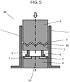
- FIG. 5 is a vertical cross-sectional view of a conventional input switch 60 (input apparatus).
- Pushing part 2, rotating part 3, and wiring part 4 are disposed in body 1.
- cam surface 5 at a bottom surface of pushing part 2 and a cam surface 55 at an upper surface of rotating part 3 contact each other.
- rotating part 3 rotates around center axis 50.
- FIG. 5 illustrates a state in which pushing part 2 is substantially pushed so that connecting part 6 and wiring pattern 7 are connected to each other.
- input switch 60 comes to be in a connected state by pushing of pushing part 2, and in a disconnected state by canceling the pushing.
- Patent Literature 1 for example, is known as prior art of this application.
- An input apparatus includes a pressing part, a spacer, a rotating cam, and a sensor.
- the pressing part is capable of reciprocating along a first direction.
- the spacer is disposed in the first direction with respect to the pressing part in the first direction and capable of reciprocating along the first direction with reciprocation of the pressing part.
- the rotating cam is disposed at a side of the spacer opposite to the pressing part and rotates in a plane perpendicular to the first direction with reciprocation of the spacer.
- the sensor detects rotation of the rotating cam.
- a plurality of projections are provided on a surface of the spacer facing the rotating cam, whereas a plurality of recesses are provided in the rotating cam at locations facing the plurality of projections of the spacer.
- a plurality of projections are provided on a surface of the rotating cam facing the spacer, whereas a plurality of recesses are provided in the spacer at locations facing the plurality of projections of the rotating cam.
- Each of the plurality of recesses has a slope.
- Pressing of the pressing part causes the spacer to be pressed, and at least one of the plurality of projections presses the slope so that the rotating cam rotates and the sensor detects rotation of the rotating cam.
- pushing part 2 In conventional input switch 60, a pushing operation performed on pushing part 2 is converted to a rotating operation of rotating part 3 by using cam surface 5 and cam surface 55.
- pushing part 2 needs to be linearly pushed accurately along center axis 50. That is, an operator needs to push pushing part 2 always in an appropriate direction. If this direction is tilted, switching between connection and disconnection of connecting part 6 and wiring pattern 7 cannot be easily performed.
- FIG. 1 is a side view of input apparatus 100 according to an exemplary embodiment.
- Input apparatus 100 includes pressing part 8, spacer 9, rotating cam 10, and sensor 12.
- Pressing part 8 can reciprocate along a first direction.
- Spacer 9 is disposed in the first direction with respect to pressing part 8 and can reciprocate along the first direction with reciprocation of the pressing part 8.
- Rotating cam 10 is disposed at a side of spacer 9 opposite to pressing part 8 and rotates in a plane perpendicular to the first direction with reciprocation of spacer 9.
- Sensor 12 detects rotation of rotating cam 10.
- a plurality of projections 13 are provided on a surface of spacer 9 facing rotating cam 10.
- a plurality of recesses 15 are provided in rotating cam 10 at locations facing projections 13 of spacer 9.
- a plurality of projections 13 may be provided on a surface of rotating cam 10 facing spacer 9 with a plurality of recesses 15 being provided in spacer 9 at locations facing projections 13 of rotating cam 10.
- Each of recesses 15 includes slope 14.
- Pressing of pressing part 8 causes spacer 9 to be pressed, and at least one of projections 13 presses slope 14 so that rotating cam 10 rotates and sensor 12 detects rotation of rotating cam 10.
- Each of spacer 9 and rotating cam 10 has an annular shape. Spacer 9 moves upward and downward in accordance with upward and downward movements of pressing part 8. Spacer 9 reduces a tilt of pressing part 8. Rotating cam 10 rotates in accordance with upward and downward movements of spacer 9. Sensor 12 detects rotation of rotating cam 10, and outputs an ON signal or an OFF signal. As illustrated in FIG. 1 , an upward direction is a direction toward pressing part 8 from spacer 9, and a downward direction (first direction) is a direction toward rotating cam 10 from spacer 9.
- Projections 13 are provided on spacer 9. Recesses 15 are provided in rotating cam 10 at locations facing projections 13. Projections 13 and recesses 15 constitute conversion mechanisms 11. Each of recesses 15 includes slope 14, first surface 34, and flat portion 36 disposed between slope 14 and first surface 34. An angle formed by slope 14 and flat portion 36 may be smaller than an angle formed by first surface 34 and flat portion 36. The angle formed by first surface 34 and flat portion 36 may be 90°. This configuration enables a pressing operation to be smoothly converted to a rotating operation.
- Spacer 9 reduces a tilt of pressing part 8, and moves upward and downward in accordance with upward and downward movements of pressing part 8. Even when an outer peripheral portion of pressing part 8 is pressed so that pressing part 8 moves upward and downward with a tilt, spacer 9 can reduce the tilt. This ensures a manipulation of input apparatus 100.
- At least one of projections 13 among projections 13 and recesses 15 faces at least a corresponding one of recesses 15. Pressing of pressing part 8 causes projections 13 to press slopes 14. Accordingly, rotating cam 10 rotates. That is, conversion mechanisms 11 convert a pressing operation (upward and downward movements) of pressing part 8 to a rotating operation (rotating operation of rotating cam 10).
- Movement of projections 13 along slopes 14 of recesses 15 causes the pressing operation to be converted to the rotating operation. That is, conversion mechanisms 11 smoothly convert the pressing operation to the rotating operation. Even in a case where at least one of projections 13 faces a corresponding one of recesses 15 and is pressed with a small force, the pressing operation is smoothly converted to the rotating operation.
- Sensor 12 detects a rotating state of rotating cam 10 in a non-contact manner.
- pressing part 8 can be pressed with a tilt in some cases.
- conversion mechanisms 11 convert the pressing operation to the rotating operation, even when pressing part 8 is pressed with a tilt, switching between ON and OFF can be stably performed.
- spacer 9 has projections 13, and rotating cam 10 facing projections 13 includes recesses 15.
- rotating cam 10 may include projections 13 with spacer 9 including recesses 15.
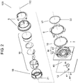
- FIG. 2 is a disassembled perspective view of input apparatus 100 according to the exemplary embodiment.
- FIG. 3 is a perspective view of input apparatus 100 according to the exemplary embodiment.
- FIG. 4 is a horizontal cross-sectional view of input apparatus 100 according to the exemplary embodiment.
- Input apparatus 100 is constituted by stacking base 16, rotating cam 10, spacer 9, click spring 17, rotating manipulation unit 18, display unit 19, and pressing part 8 in this order on board 46 provided with sensor 12. Pressing part 8 moves upward and downward along center axis 110. Movement of pressing part 8 is transmitted to spacer 9.
- Base 16 When an outer peripheral portion of pressing part 8 is partially pressed, pressing part 8 moves upward and downward with a tilt.
- Base 16 includes base portion 40 and guide portion 42.
- Guide portion 42 is formed around rotating cam 10 and projects from base portion 40 toward spacer 16. Since spacer 9 is guided by guide portion 42 of base 16, a tilt of spacer 9 is reduced. Specifically, even when pressing part 8 moves upward and downward with a relatively large tilt, spacer 9 hardly tilts while moving upward and downward. That is, the tilt of spacer 9 caused by upward and downward movements of spacer 9 is smaller than the tilt of pressing part 8 caused by upward and downward movements of pressing part 8.
- a photointerrupter is preferably used.
- the use of the photointerrupter enables detection of rotation of rotating cam 10 without application of a mechanical stress or resistance to a rotating operation of rotating cam 10.
- a push type or a lever type connecting part may be used so that movement of shielding part 20 causes the connecting part to turn ON or OFF (contact or non-contact).
- pressing part 8 When the operator cancels pressing (removes a hand or a finger from pressing part 8), pressing part 8 returns to an initial position.
- the initial position herein is a state in which projections 13 are not contact with slopes 14, and a highest position to which pressing part 8 rises in FIG. 1 .
- slopes 14 have the function of converting a pressing operation to a rotating operation with pressing of pressing part 8. In addition, slopes 14 also have the function of converting a rotating operation to a pressing operation with canceling of pressing of pressing part 8.
- Slopes 14 also have the function of a reversible operation. Specifically, when projections 13 move on slopes 14, a pressing operation is converted to a rotating operation, and when projections 13 are separated from slopes 14, a rotating operation is converted to a pressing operation (linear operation). To achieve this function, it is sufficient that one recess 15 corresponds to one slope 14. That is, as illustrated in FIG. 1 , in each of recesses 15, the angle formed by first surface 34 and flat portion 36 may be 90°.
- conversion mechanisms 11 are constituted by projections 13 and recesses 15. Projections 13 and recesses 15 are disposed in the same circumference. In this manner, conversion from a pressing operation to a rotating operation and conversion from a rotating operation to a pressing operation (linear operation) can be smoothly performed.
- Projections 13 are provided on annular spacer 9. Recesses 15 are provided in annular rotating cam 10. Thus, pressing part 8 can easily rotate rotating cam 10 with a moment. For this reason, all projections 13 do not need to press all recesses 15. That is, pressing part 8 can rotate rotating cam 10 only by pressing at least one recess 15 with at least one projection 13.
- FIG. 1 illustrates a case where the operator presses a left side of pressing part 8. Even in this case, projections 13 at the left side press recesses 15 so that the pressing force is easily converted to a rotating force of rotating cam 10. Even when the operator performs an insufficient pressing manipulation, input apparatus 100 can sufficiently detect this manipulation. Thus, input apparatus 100 has high operability.
- the left side herein refers to a side where sensor 12 is present in FIG. 1 .
- Conversion mechanisms 11 are preferably disposed on spacer 9 and rotating cam 10 at substantially regular intervals.
- conversion mechanisms 11 are disposed at six locations with intervals of about 60°.
- the interval of conversion mechanisms 11 may slightly vary, however.
- Columnar display unit 19 is fixed to base 16 and projects toward pressing part 8. Display unit 19 does not rotate. Thus, display unit 19 can prevent pressing part 8 from being pressed to an extremely displaced location or direction (in a so-called extremely local pressing state).
- spacer 9 moves downward along center axis 110 in accordance with pressing part 8. Specifically, when the operator presses pressing part 8, an outer peripheral portion of the bottom surface of rotating manipulation unit 18 disposed inside pressing part 8 presses spacer 9 downward.
- Pressing part 8 can perform a rotation manipulation as well as the pressing manipulation.
- spacer 9 does not in conjunction with the rotation, and instead, rotating manipulation unit 18 inside pressing part 8 rotates in conjunction with the rotation of pressing part 8.
- Protrusion 21 (first protrusion) is provided on a bottom surface of rotating manipulation unit 18.
- Protrusion 22 (second protrusion) is provided on a side of click spring 17 facing rotating manipulation unit 18.
- click spring 17 When pressing part 8 is pressed, click spring 17 is also pressed through rotating manipulation unit 18. At this time, click spring 17 generates an upward lifting force, and when pressing of pressing part 8 is canceled, an upward force toward the initial position is applied to pressing part 8. Thus, it is ensured that pressing part 8 easily returns to the initial position.
- input apparatus 100 is applied to an air conditioner and the rotating manipulation is used as a manipulation for selecting a set temperature, and a pressing manipulation is used as a manipulation for determining the selection.
- pressing part 8 and rotating manipulation unit 18 are different elements.
- pressing part 8 and rotating manipulation unit 18 may be integrated as pressing part 8.
- base 16 preferably includes detection mechanism 23.
- Detection mechanism 23 is constituted by first pressing spring 24 and first contact body 25.
- First pressing spring 24 is made of an elastic material.
- First contact body 25 is connected to a front end of first pressing spring 24 near rotating cam 10.
- FIG. 4 illustrates a state (initial state) where pressing part 8 illustrated in FIG. 1 is not pressed. When pressing part 8 is pressed, rotating cam 10 rotates in direction R in FIG. 4 .
- first contact body 25 is engaged with uneven portion 26 provided in an outer peripheral portion of rotating cam 10.
- Uneven portion 26 is constituted by projections 120 and 122 and recess 124. Projections 120 and 122 project outward at the outer periphery of rotating cam 10. Recess 124 is provided between projection 120 and projection 122.
- first contact body 25 is engaged with recess 124 of uneven portion 26.
- first contact body 25 moves from recess 124 of uneven portion 26 to the outer periphery of rotating cam 10 outside the uneven portion 26 across projection 120.
- shielding part 20 illustrated in FIG. 3 reaches a location corresponding to sensor 12, sensor 12 detects the rotation of rotating cam 10. That is, sensor 12 detects that the operator pressed input apparatus 100. Then, at the time when shielding part 20 reaches sensor 12 and sensor 12 detects the pressing manipulation, first contact body 25 is released from uneven portion 26.
- Projection 120 opposite to recess 124 of uneven portion 26 significantly tilts.
- a force applied on first contact body 25 from uneven portion 26 to the direction of first pressing spring 24 suddenly disappears. Consequently, the repulsive force accumulated in first pressing spring 24 up to this time is rapidly released, and the released repulsive force causes first contact body 25 to hit the outer periphery of rotating cam 10.
- base 16 of input apparatus 100 includes detection mechanism 23 projecting from guide portion 42 toward the outer periphery of base portion 40.
- Detection mechanism 23 includes first pressing spring 24 and first contact body 25 disposed at a front end of first pressing spring 24.
- Rotating cam 10 includes uneven portion 26 on the outer peripheral portion thereof. In the initial state, first contact body 25 is engaged with uneven portion 26, and is released from uneven portion 26 by rotation of rotating cam 10.
- first contact body 25 is used as an example.
- first contact body 25 is not limited to such a spherical shape.
- First contact body 25 only needs to have a shape that allows a positional relationship between first contact body 25 and uneven portion 26 of rotating cam 10 to change smoothly with first contact body 25 and uneven portion 26 being in contact with each other.
- the initial position herein is a state where projections 13 do not press slopes 14 (projections 13 are not in contact with slopes 14), and corresponds to a highest position to which pressing part 8 rises in FIG. 1 .
- base 16 may include return mechanism 27. In this case, the operation described above can be accurately performed.
- Return mechanism 27 is constituted by second pressing spring 28 and second contact body 29.
- Second pressing spring 28 is made of an elastic material.
- Second contact body 29 is connected to a front end of second pressing spring 28 near rotating cam 10.
- FIG. 4 illustrates the initial state where pressing part 8 illustrated in FIG. 1 is not pressed. When pressing part 8 is pressed, rotating cam 10 rotates in direction R illustrated in FIG. 4 .
- second pressing spring 28 presses outer protrusion portion 30 through second contact body 29.
- Outer protrusion portion 30 is disposed in an outer peripheral portion of rotating cam 10.
- Outer protrusion portion 30 is provided to prevent rotating cam 10 from moving in the direction opposite to direction R by a predetermined degree. That is, outer protrusion portion 30 stops movement of rotating cam 10 in the direction opposite to direction R at a limit position.
- base 16 of input apparatus 100 includes return mechanism 27 projecting from guide portion 42 toward the outer periphery of base portion 40.
- Return mechanism 27 includes second pressing spring 28 and second contact body 29 disposed at a front end of second pressing spring 28.
- Rotating cam 10 includes outer protrusion portion 30 in the outer periphery thereof. Pressing of second contact body 29 by outer protrusion portion 30 restricts rotation of rotating cam 10.
- Detection mechanism 23 and return mechanism 27 are preferably defined to satisfy the following relationship.
- a force with which return mechanism 27 presses outer protrusion portion 30 is always greater than a resistance to rotation applied to rotating cam 10 when rotating cam 10 rotates in the direction opposite to direction R.
- pressing part 8 always returns to the initial position.
- a sensor 12 constituted by a light-emitting part (not shown) and a light-receiving part (not shown) is disposed on board 46.
- a plurality of such sensors 12 may be disposed on board 46.
- the operator presses input apparatus 100 to select one of an ON state or an OFF state.
- the operator can control not only the ON or OFF state of input apparatus 100 but also the pressing manipulation stepwise or quantitatively.
- the sensor(s) 12 may not be disposed on board 46 and may be disposed on, for example, base 16.
- conversion mechanisms 11 can smoothly convert a pressing operation to a rotating operation.
- the operator can press tilted pressing part 8, thus obtaining input apparatus 100 with high operability.
- An input apparatus has the advantage of high operability, and is useful for various types of electronic equipment.
Applications Claiming Priority (2)
| Application Number | Priority Date | Filing Date | Title |
|---|---|---|---|
| JP2014082464 | 2014-04-14 | ||
| PCT/JP2015/001877 WO2015159494A1 (fr) | 2014-04-14 | 2015-04-01 | Appareil d'entrée |
Publications (3)
| Publication Number | Publication Date |
|---|---|
| EP3133628A1 true EP3133628A1 (fr) | 2017-02-22 |
| EP3133628A4 EP3133628A4 (fr) | 2017-04-19 |
| EP3133628B1 EP3133628B1 (fr) | 2018-12-12 |
Family
ID=54323721
Family Applications (1)
| Application Number | Title | Priority Date | Filing Date |
|---|---|---|---|
| EP15780137.4A Active EP3133628B1 (fr) | 2014-04-14 | 2015-04-01 | Appareil d'entrée |
Country Status (4)
| Country | Link |
|---|---|
| US (1) | US10020137B2 (fr) |
| EP (1) | EP3133628B1 (fr) |
| JP (1) | JP6660527B2 (fr) |
| WO (1) | WO2015159494A1 (fr) |
Families Citing this family (8)
| Publication number | Priority date | Publication date | Assignee | Title |
|---|---|---|---|---|
| CN207529869U (zh) * | 2017-12-18 | 2018-06-22 | 东莞辰达电器有限公司 | 一种带显示功能的旋钮 |
| JP6952249B2 (ja) * | 2018-02-23 | 2021-10-20 | パナソニックIpマネジメント株式会社 | 複合操作入力装置 |
| CN108766825B (zh) * | 2018-05-12 | 2023-11-24 | 惠州市德赛西威汽车电子股份有限公司 | 一种车载旋钮组件 |
| CN108597936A (zh) * | 2018-05-12 | 2018-09-28 | 惠州市德赛西威汽车电子股份有限公司 | 一种新型的结合显示屏的旋钮按键结构 |
| CN110631613A (zh) * | 2018-06-21 | 2019-12-31 | 广东升威电子制品有限公司 | 一种带按压开关的光电编码器 |
| EP3866182A4 (fr) * | 2018-10-09 | 2021-12-01 | Panasonic Intellectual Property Management Co., Ltd. | Dispositif d'entrée de type à presse et dispositif d'entrée de type à presse-rotation |
| CN113168988B (zh) | 2018-11-20 | 2023-10-31 | 阿尔卑斯阿尔派株式会社 | 操作装置 |
| JP7077924B2 (ja) * | 2018-11-29 | 2022-05-31 | 株式会社デンソー | スイッチ装置 |
Family Cites Families (8)
| Publication number | Priority date | Publication date | Assignee | Title |
|---|---|---|---|---|
| US3226991A (en) * | 1962-12-17 | 1966-01-04 | United Carr Fastener Corp | Indexing device for a rotary snap switch |
| JPS5219181Y2 (fr) * | 1972-02-08 | 1977-04-30 | ||
| US5132499A (en) | 1989-05-16 | 1992-07-21 | Judco Manufacturing, Inc. | Pre-loaded switching apparatus and method of operation |
| US6180905B1 (en) * | 2000-01-03 | 2001-01-30 | Trw Inc. | Two position pushbutton switch with illuminated button |
| US6743995B2 (en) * | 2002-06-06 | 2004-06-01 | Judco Manufacturing, Inc. | Quiet pushbutton switch |
| JP2006294259A (ja) | 2005-04-05 | 2006-10-26 | Alps Electric Co Ltd | スイッチ装置 |
| JP5017180B2 (ja) * | 2008-05-30 | 2012-09-05 | アルプス電気株式会社 | プッシュスイッチ装置 |
| DE102011083524B4 (de) | 2011-09-27 | 2017-04-06 | Behr-Hella Thermocontrol Gmbh | Dreh-/Drück-Bedienvorrichtung für ein Mensch-Maschine-Interface |
-
2015
- 2015-04-01 JP JP2016513624A patent/JP6660527B2/ja active Active
- 2015-04-01 EP EP15780137.4A patent/EP3133628B1/fr active Active
- 2015-04-01 WO PCT/JP2015/001877 patent/WO2015159494A1/fr active Application Filing
- 2015-04-01 US US15/301,865 patent/US10020137B2/en active Active
Also Published As
| Publication number | Publication date |
|---|---|
| EP3133628A4 (fr) | 2017-04-19 |
| EP3133628B1 (fr) | 2018-12-12 |
| US10020137B2 (en) | 2018-07-10 |
| JP6660527B2 (ja) | 2020-03-11 |
| US20170117106A1 (en) | 2017-04-27 |
| WO2015159494A1 (fr) | 2015-10-22 |
| JPWO2015159494A1 (ja) | 2017-04-13 |
Similar Documents
| Publication | Publication Date | Title |
|---|---|---|
| EP3133628B1 (fr) | Appareil d'entrée | |
| US8283583B2 (en) | Switch | |
| US9672994B2 (en) | Device for operating multiple functions in a motor vehicle | |
| US9182825B2 (en) | Input device comprising a touch-sensitive input surface | |
| KR101425949B1 (ko) | 밀기방식 신호입력장치 | |
| JP5415970B2 (ja) | スイッチ機構並びに入力装置 | |
| US7781686B2 (en) | Operating element with a central pushbutton | |
| KR100996664B1 (ko) | 고정형 마우스 | |
| US11152170B2 (en) | Input device | |
| KR101381611B1 (ko) | 조작장치 | |
| JP6209575B2 (ja) | 多方向入力装置 | |
| US20170336876A1 (en) | Signal input device and electronic equipment driving device using same | |
| US9082559B2 (en) | Capacitive switches | |
| US9724599B2 (en) | Operator and operating device | |
| JP2015210995A (ja) | 多方向入力装置及び情報処理装置 | |
| JP2011086490A (ja) | スライド操作式スイッチ | |
| TWI640902B (zh) | 輸入裝置 | |
| JP6204232B2 (ja) | 入力装置 | |
| WO2018042712A1 (fr) | Dispositif d'entrée | |
| KR20160011516A (ko) | 밀기방식 신호입력장치 | |
| WO2016121336A1 (fr) | Dispositif commutateur | |
| JP2007103140A (ja) | 多方向入力装置 | |
| JP2015210996A (ja) | 多方向入力装置及び情報処理装置 | |
| JP2007103275A (ja) | 入力装置 |
Legal Events
| Date | Code | Title | Description |
|---|---|---|---|
| STAA | Information on the status of an ep patent application or granted ep patent |
Free format text: STATUS: THE INTERNATIONAL PUBLICATION HAS BEEN MADE |
|
| PUAI | Public reference made under article 153(3) epc to a published international application that has entered the european phase |
Free format text: ORIGINAL CODE: 0009012 |
|
| STAA | Information on the status of an ep patent application or granted ep patent |
Free format text: STATUS: REQUEST FOR EXAMINATION WAS MADE |
|
| 17P | Request for examination filed |
Effective date: 20160922 |
|
| AK | Designated contracting states |
Kind code of ref document: A1 Designated state(s): AL AT BE BG CH CY CZ DE DK EE ES FI FR GB GR HR HU IE IS IT LI LT LU LV MC MK MT NL NO PL PT RO RS SE SI SK SM TR |
|
| AX | Request for extension of the european patent |
Extension state: BA ME |
|
| A4 | Supplementary search report drawn up and despatched |
Effective date: 20170321 |
|
| RIC1 | Information provided on ipc code assigned before grant |
Ipc: H01H 25/06 20060101ALI20170315BHEP Ipc: H01H 13/20 20060101AFI20170315BHEP |
|
| DAV | Request for validation of the european patent (deleted) | ||
| DAX | Request for extension of the european patent (deleted) | ||
| GRAP | Despatch of communication of intention to grant a patent |
Free format text: ORIGINAL CODE: EPIDOSNIGR1 |
|
| STAA | Information on the status of an ep patent application or granted ep patent |
Free format text: STATUS: GRANT OF PATENT IS INTENDED |
|
| INTG | Intention to grant announced |
Effective date: 20180824 |
|
| RAP1 | Party data changed (applicant data changed or rights of an application transferred) |
Owner name: PANASONIC INTELLECTUAL PROPERTY MANAGEMENT CO., LT |
|
| GRAS | Grant fee paid |
Free format text: ORIGINAL CODE: EPIDOSNIGR3 |
|
| GRAA | (expected) grant |
Free format text: ORIGINAL CODE: 0009210 |
|
| STAA | Information on the status of an ep patent application or granted ep patent |
Free format text: STATUS: THE PATENT HAS BEEN GRANTED |
|
| AK | Designated contracting states |
Kind code of ref document: B1 Designated state(s): AL AT BE BG CH CY CZ DE DK EE ES FI FR GB GR HR HU IE IS IT LI LT LU LV MC MK MT NL NO PL PT RO RS SE SI SK SM TR |
|
| REG | Reference to a national code |
Ref country code: GB Ref legal event code: FG4D |
|
| REG | Reference to a national code |
Ref country code: CH Ref legal event code: EP |
|
| REG | Reference to a national code |
Ref country code: AT Ref legal event code: REF Ref document number: 1077085 Country of ref document: AT Kind code of ref document: T Effective date: 20181215 |
|
| REG | Reference to a national code |
Ref country code: DE Ref legal event code: R096 Ref document number: 602015021491 Country of ref document: DE |
|
| REG | Reference to a national code |
Ref country code: IE Ref legal event code: FG4D |
|
| REG | Reference to a national code |
Ref country code: NL Ref legal event code: MP Effective date: 20181212 |
|
| REG | Reference to a national code |
Ref country code: LT Ref legal event code: MG4D |
|
| PG25 | Lapsed in a contracting state [announced via postgrant information from national office to epo] |
Ref country code: NO Free format text: LAPSE BECAUSE OF FAILURE TO SUBMIT A TRANSLATION OF THE DESCRIPTION OR TO PAY THE FEE WITHIN THE PRESCRIBED TIME-LIMIT Effective date: 20190312 Ref country code: BG Free format text: LAPSE BECAUSE OF FAILURE TO SUBMIT A TRANSLATION OF THE DESCRIPTION OR TO PAY THE FEE WITHIN THE PRESCRIBED TIME-LIMIT Effective date: 20190312 Ref country code: ES Free format text: LAPSE BECAUSE OF FAILURE TO SUBMIT A TRANSLATION OF THE DESCRIPTION OR TO PAY THE FEE WITHIN THE PRESCRIBED TIME-LIMIT Effective date: 20181212 Ref country code: LT Free format text: LAPSE BECAUSE OF FAILURE TO SUBMIT A TRANSLATION OF THE DESCRIPTION OR TO PAY THE FEE WITHIN THE PRESCRIBED TIME-LIMIT Effective date: 20181212 Ref country code: LV Free format text: LAPSE BECAUSE OF FAILURE TO SUBMIT A TRANSLATION OF THE DESCRIPTION OR TO PAY THE FEE WITHIN THE PRESCRIBED TIME-LIMIT Effective date: 20181212 Ref country code: HR Free format text: LAPSE BECAUSE OF FAILURE TO SUBMIT A TRANSLATION OF THE DESCRIPTION OR TO PAY THE FEE WITHIN THE PRESCRIBED TIME-LIMIT Effective date: 20181212 Ref country code: FI Free format text: LAPSE BECAUSE OF FAILURE TO SUBMIT A TRANSLATION OF THE DESCRIPTION OR TO PAY THE FEE WITHIN THE PRESCRIBED TIME-LIMIT Effective date: 20181212 |
|
| REG | Reference to a national code |
Ref country code: AT Ref legal event code: MK05 Ref document number: 1077085 Country of ref document: AT Kind code of ref document: T Effective date: 20181212 |
|
| PG25 | Lapsed in a contracting state [announced via postgrant information from national office to epo] |
Ref country code: SE Free format text: LAPSE BECAUSE OF FAILURE TO SUBMIT A TRANSLATION OF THE DESCRIPTION OR TO PAY THE FEE WITHIN THE PRESCRIBED TIME-LIMIT Effective date: 20181212 Ref country code: AL Free format text: LAPSE BECAUSE OF FAILURE TO SUBMIT A TRANSLATION OF THE DESCRIPTION OR TO PAY THE FEE WITHIN THE PRESCRIBED TIME-LIMIT Effective date: 20181212 Ref country code: GR Free format text: LAPSE BECAUSE OF FAILURE TO SUBMIT A TRANSLATION OF THE DESCRIPTION OR TO PAY THE FEE WITHIN THE PRESCRIBED TIME-LIMIT Effective date: 20190313 Ref country code: RS Free format text: LAPSE BECAUSE OF FAILURE TO SUBMIT A TRANSLATION OF THE DESCRIPTION OR TO PAY THE FEE WITHIN THE PRESCRIBED TIME-LIMIT Effective date: 20181212 |
|
| PG25 | Lapsed in a contracting state [announced via postgrant information from national office to epo] |
Ref country code: NL Free format text: LAPSE BECAUSE OF FAILURE TO SUBMIT A TRANSLATION OF THE DESCRIPTION OR TO PAY THE FEE WITHIN THE PRESCRIBED TIME-LIMIT Effective date: 20181212 |
|
| PG25 | Lapsed in a contracting state [announced via postgrant information from national office to epo] |
Ref country code: IT Free format text: LAPSE BECAUSE OF FAILURE TO SUBMIT A TRANSLATION OF THE DESCRIPTION OR TO PAY THE FEE WITHIN THE PRESCRIBED TIME-LIMIT Effective date: 20181212 Ref country code: PL Free format text: LAPSE BECAUSE OF FAILURE TO SUBMIT A TRANSLATION OF THE DESCRIPTION OR TO PAY THE FEE WITHIN THE PRESCRIBED TIME-LIMIT Effective date: 20181212 Ref country code: PT Free format text: LAPSE BECAUSE OF FAILURE TO SUBMIT A TRANSLATION OF THE DESCRIPTION OR TO PAY THE FEE WITHIN THE PRESCRIBED TIME-LIMIT Effective date: 20190412 Ref country code: CZ Free format text: LAPSE BECAUSE OF FAILURE TO SUBMIT A TRANSLATION OF THE DESCRIPTION OR TO PAY THE FEE WITHIN THE PRESCRIBED TIME-LIMIT Effective date: 20181212 |
|
| PG25 | Lapsed in a contracting state [announced via postgrant information from national office to epo] |
Ref country code: EE Free format text: LAPSE BECAUSE OF FAILURE TO SUBMIT A TRANSLATION OF THE DESCRIPTION OR TO PAY THE FEE WITHIN THE PRESCRIBED TIME-LIMIT Effective date: 20181212 Ref country code: IS Free format text: LAPSE BECAUSE OF FAILURE TO SUBMIT A TRANSLATION OF THE DESCRIPTION OR TO PAY THE FEE WITHIN THE PRESCRIBED TIME-LIMIT Effective date: 20190412 Ref country code: RO Free format text: LAPSE BECAUSE OF FAILURE TO SUBMIT A TRANSLATION OF THE DESCRIPTION OR TO PAY THE FEE WITHIN THE PRESCRIBED TIME-LIMIT Effective date: 20181212 Ref country code: SK Free format text: LAPSE BECAUSE OF FAILURE TO SUBMIT A TRANSLATION OF THE DESCRIPTION OR TO PAY THE FEE WITHIN THE PRESCRIBED TIME-LIMIT Effective date: 20181212 Ref country code: SM Free format text: LAPSE BECAUSE OF FAILURE TO SUBMIT A TRANSLATION OF THE DESCRIPTION OR TO PAY THE FEE WITHIN THE PRESCRIBED TIME-LIMIT Effective date: 20181212 |
|
| REG | Reference to a national code |
Ref country code: DE Ref legal event code: R097 Ref document number: 602015021491 Country of ref document: DE |
|
| PLBE | No opposition filed within time limit |
Free format text: ORIGINAL CODE: 0009261 |
|
| STAA | Information on the status of an ep patent application or granted ep patent |
Free format text: STATUS: NO OPPOSITION FILED WITHIN TIME LIMIT |
|
| PG25 | Lapsed in a contracting state [announced via postgrant information from national office to epo] |
Ref country code: DK Free format text: LAPSE BECAUSE OF FAILURE TO SUBMIT A TRANSLATION OF THE DESCRIPTION OR TO PAY THE FEE WITHIN THE PRESCRIBED TIME-LIMIT Effective date: 20181212 Ref country code: AT Free format text: LAPSE BECAUSE OF FAILURE TO SUBMIT A TRANSLATION OF THE DESCRIPTION OR TO PAY THE FEE WITHIN THE PRESCRIBED TIME-LIMIT Effective date: 20181212 Ref country code: SI Free format text: LAPSE BECAUSE OF FAILURE TO SUBMIT A TRANSLATION OF THE DESCRIPTION OR TO PAY THE FEE WITHIN THE PRESCRIBED TIME-LIMIT Effective date: 20181212 |
|
| 26N | No opposition filed |
Effective date: 20190913 |
|
| REG | Reference to a national code |
Ref country code: CH Ref legal event code: PL |
|
| REG | Reference to a national code |
Ref country code: BE Ref legal event code: MM Effective date: 20190430 |
|
| GBPC | Gb: european patent ceased through non-payment of renewal fee |
Effective date: 20190401 |
|
| PG25 | Lapsed in a contracting state [announced via postgrant information from national office to epo] |
Ref country code: LU Free format text: LAPSE BECAUSE OF NON-PAYMENT OF DUE FEES Effective date: 20190401 Ref country code: MC Free format text: LAPSE BECAUSE OF FAILURE TO SUBMIT A TRANSLATION OF THE DESCRIPTION OR TO PAY THE FEE WITHIN THE PRESCRIBED TIME-LIMIT Effective date: 20181212 |
|
| PG25 | Lapsed in a contracting state [announced via postgrant information from national office to epo] |
Ref country code: GB Free format text: LAPSE BECAUSE OF NON-PAYMENT OF DUE FEES Effective date: 20190401 Ref country code: LI Free format text: LAPSE BECAUSE OF NON-PAYMENT OF DUE FEES Effective date: 20190430 Ref country code: CH Free format text: LAPSE BECAUSE OF NON-PAYMENT OF DUE FEES Effective date: 20190430 |
|
| PG25 | Lapsed in a contracting state [announced via postgrant information from national office to epo] |
Ref country code: FR Free format text: LAPSE BECAUSE OF NON-PAYMENT OF DUE FEES Effective date: 20190430 Ref country code: BE Free format text: LAPSE BECAUSE OF NON-PAYMENT OF DUE FEES Effective date: 20190430 |
|
| PG25 | Lapsed in a contracting state [announced via postgrant information from national office to epo] |
Ref country code: TR Free format text: LAPSE BECAUSE OF FAILURE TO SUBMIT A TRANSLATION OF THE DESCRIPTION OR TO PAY THE FEE WITHIN THE PRESCRIBED TIME-LIMIT Effective date: 20181212 |
|
| PG25 | Lapsed in a contracting state [announced via postgrant information from national office to epo] |
Ref country code: IE Free format text: LAPSE BECAUSE OF NON-PAYMENT OF DUE FEES Effective date: 20190401 |
|
| PG25 | Lapsed in a contracting state [announced via postgrant information from national office to epo] |
Ref country code: CY Free format text: LAPSE BECAUSE OF FAILURE TO SUBMIT A TRANSLATION OF THE DESCRIPTION OR TO PAY THE FEE WITHIN THE PRESCRIBED TIME-LIMIT Effective date: 20181212 |
|
| PG25 | Lapsed in a contracting state [announced via postgrant information from national office to epo] |
Ref country code: MT Free format text: LAPSE BECAUSE OF FAILURE TO SUBMIT A TRANSLATION OF THE DESCRIPTION OR TO PAY THE FEE WITHIN THE PRESCRIBED TIME-LIMIT Effective date: 20181212 Ref country code: HU Free format text: LAPSE BECAUSE OF FAILURE TO SUBMIT A TRANSLATION OF THE DESCRIPTION OR TO PAY THE FEE WITHIN THE PRESCRIBED TIME-LIMIT; INVALID AB INITIO Effective date: 20150401 |
|
| PG25 | Lapsed in a contracting state [announced via postgrant information from national office to epo] |
Ref country code: MK Free format text: LAPSE BECAUSE OF FAILURE TO SUBMIT A TRANSLATION OF THE DESCRIPTION OR TO PAY THE FEE WITHIN THE PRESCRIBED TIME-LIMIT Effective date: 20181212 |
|
| PGFP | Annual fee paid to national office [announced via postgrant information from national office to epo] |
Ref country code: DE Payment date: 20230420 Year of fee payment: 9 |
|
| REG | Reference to a national code |
Ref country code: DE Ref legal event code: R081 Ref document number: 602015021491 Country of ref document: DE Owner name: PANASONIC AUTOMOTIVE SYSTEMS CO., LTD., YOKOHA, JP Free format text: FORMER OWNER: PANASONIC INTELLECTUAL PROPERTY MANAGEMENT CO., LTD., OSAKA, JP |