EP3133217A1 - Wc dispensing container - Google Patents
Wc dispensing container Download PDFInfo
- Publication number
- EP3133217A1 EP3133217A1 EP16183401.5A EP16183401A EP3133217A1 EP 3133217 A1 EP3133217 A1 EP 3133217A1 EP 16183401 A EP16183401 A EP 16183401A EP 3133217 A1 EP3133217 A1 EP 3133217A1
- Authority
- EP
- European Patent Office
- Prior art keywords
- wall
- holding device
- chambers
- toilet bowl
- front wall
- Prior art date
- Legal status (The legal status is an assumption and is not a legal conclusion. Google has not performed a legal analysis and makes no representation as to the accuracy of the status listed.)
- Withdrawn
Links
Images
Classifications
-
- E—FIXED CONSTRUCTIONS
- E03—WATER SUPPLY; SEWERAGE
- E03D—WATER-CLOSETS OR URINALS WITH FLUSHING DEVICES; FLUSHING VALVES THEREFOR
- E03D9/00—Sanitary or other accessories for lavatories ; Devices for cleaning or disinfecting the toilet room or the toilet bowl; Devices for eliminating smells
- E03D9/02—Devices adding a disinfecting, deodorising, or cleaning agent to the water while flushing
- E03D9/03—Devices adding a disinfecting, deodorising, or cleaning agent to the water while flushing consisting of a separate container with an outlet through which the agent is introduced into the flushing water, e.g. by suction ; Devices for agents in direct contact with flushing water
- E03D9/032—Devices connected to or dispensing into the bowl
-
- E—FIXED CONSTRUCTIONS
- E03—WATER SUPPLY; SEWERAGE
- E03D—WATER-CLOSETS OR URINALS WITH FLUSHING DEVICES; FLUSHING VALVES THEREFOR
- E03D9/00—Sanitary or other accessories for lavatories ; Devices for cleaning or disinfecting the toilet room or the toilet bowl; Devices for eliminating smells
- E03D9/02—Devices adding a disinfecting, deodorising, or cleaning agent to the water while flushing
- E03D2009/024—Devices adding a disinfecting, deodorising, or cleaning agent to the water while flushing using a solid substance
Definitions
- the present invention relates to a holding device and a WC-drug delivery device for mounting in a toilet bowl.
- Such holding devices also known as “toilet bowls" are used to hold chemical compositions which are usually released during a rinsing process at least partially into the rinsing water of the toilet bowl.
- Such compositions are referred to hereinafter as "active ingredients”.
- active ingredients can represent a cleaning agent, but on the other hand also contain other chemical compositions, in particular fragrance compositions that are less in the rinse water, but rather (often preferably exclusively) to the ambient air of the toilet bowl, ie in a toilet room to be discharged.
- the cleaning agent is dispensed into the rinsing water on demand, ie in a rinsing process, while fragrance of a fragrance unit is also continuously released into the ambient air.
- cleaning and fragrance agents are kept in separate chambers in some embodiments known from practice. Examples of this show the WO 2006/013322 A1 or the WO 2015/048657 A1 , However, variants are also known in practice which combine cleaning and fragrancing agents in one composition, ie in an active substance molding in a chamber.
- a device which comprises a front shell and a rear shell, which can be connected to one another and hung together by means of a suspension device in the edge of a toilet bowl.
- the interior of the holding device is subdivided into a plurality of separate receiving areas, namely into a first receiving area for receiving a cleaning agent unit, a second receiving area for receiving a fragrance unit and a third receiving area, again for receiving a cleaning agent unit.
- This division into contiguous receiving areas is realized by folding the front shell and the rear shell together, wherein in each case complementarily arranged webs in the front and the rear shell provide for a subdivision into the three receiving areas.
- the holding device serves as a holder for active ingredient tablets.
- These are preferably designed in the form of polygonal blocks of active substance and are therefore referred to below as such, without limiting the generality to this special shaped body.
- Polygonal is generally polygonal. Thus, explicitly no spherical or cylindrical shapes are included, but in contrast forms such as pyramids, rhombohedron, cuboid and / or cubes.
- the holding device thus absorbs the drug blocks in designated areas. It is hung with a hanger on one edge of a toilet bowl. The suspension device thus keeps it in position during any rinsing operations.
- the holding device For holding the blocks of active substance, the holding device comprises at least three cup chambers, that is, at least one middle and two outer.
- cup chamber describes a small chamber, ie a cavity enclosed by outer walls, with openings distributed in a basket over the surface.
- the terms “cup chamber” and “chamber” are used interchangeably.
- the basket chambers are arranged side by side in a longitudinal direction in the manner of a substantially rectilinear chain.
- a cup chamber is thus lined up in a chain between the adjacent cup chambers and the centers of the Chambers are essentially only shifted in the longitudinal direction.
- "essentially” here means that they optionally have at most a slight curvature, but preferably form a straight line.
- the longitudinal direction is thus defined as an axis through the center points of the basket chambers and is perpendicular to the suspension device.
- the cup chambers are positioned over the suspension device below along the lower edge of the rim of the toilet bowl. They form almost a bowstring to the toilet bowl.
- lower edge here is meant the projection inside the toilet bowl, from which the flushing water emerges, in contrast to the upper edge, on which the toilet seat rests.
- the basket chambers each have a hinged in the toilet bowl in the intended state of the holding device downwardly facing bottom. Furthermore, they each have a front wall which faces away from the nearest wall of the toilet bowl in the state of the holding device suspended as intended in the toilet bowl and which has viewing apertures. These are used to control the consumption level of the drug blocks. The user can thus visually determine through these openings how much active substance is still present.
- the cup chambers comprise a facing in the direction of the suspension ceiling wall, which extends from the front wall to the rear only to a central region above the floor and facing away from the front wall, thus facing the nearest wall of the toilet bowl, rear wall. This is preferably designed with water outlet.
- cup chambers each have a cutout as a water inlet, which extends from the trailing edge of the ceiling wall to the upper edge of the rear wall.
- Two in the chain outside arranged basket chambers each have on their outer sides outer side walls. These connect on just the sides that do not point to the central basket, the bottom, the ceiling wall, the front wall and the rear wall and also extend in the area laterally of the water inlet as a side splash guard. Unlike the embodiments known from practice, is this reduces the water input on the outer sides.
- the basket chambers are thus essentially enclosed on all sides by walls. An exception to this is the cut-out area of the imaginary top edge where the water inlet is located.
- a WC active substance delivery device comprises a holding device according to the invention and, arranged therein, a number of active substance shaped bodies.
- a drug block in a cup chamber, as already stated above.
- the bulk of the water flows through the water inlet into the cup chamber.
- the drug block dissolves its active ingredients over time, especially from the back.
- the front visible side is retained longer, which improves the visual impression.
- the outer sides are further pulled up to reduce the water flowing in from there and designed as a splash guard. Otherwise, especially at the outer sides of the WC active agent delivery device, a greater flow of water occurs, ie.
- the holding device borders on the edge of the toilet bowl, like a bowstring.
- the rinse water in the toilet bowl is usually added centrally from behind and then flows horizontally along the edge along, so that the water surge mainly meets laterally on the basket.
- the outer active ingredient blocks are more uniformly flowed and consumed, so that in particular the form visible from the front is retained longer.
- this has the advantage, in addition to optical advantages, that the drug blocks are completely coincidentally completely worn out and thus can be used more efficiently. Because so the consumer can advantageously conveniently exchange the entire holding device, without having to wait long, possibly all drug residues are solved.
- the basket chambers are formed as a single basket with two connecting the rear wall and the front wall side walls. That means they each have their own walls and are separated from the neighboring baskets. This separation thus takes place by means of an actual distance between adjacent cup chambers and not just like a single large cup through a dividing wall.
- the cup chambers as well as the drug blocks can basically have different shapes and sizes; however, preferred are uniform geometries and dimensions. Because this advantageously simplifies the manufacturing process.
- adjacent individual baskets are preferably connected to each other by a web.
- the webs are preferably arranged in the region of a mean height of the chambers and separate the individual cup chambers from each other.
- the outer side walls of the outside arranged Körbchenschhuntn also extend in the area laterally beyond the water inlet on the rear wall to the ceiling wall and back beyond the ceiling wall to the rear wall. This further limits the lateral entry of water while maintaining the given basket height and thus promotes a uniform removal rate on the sides of the active substance block.
- the rate of removal refers to the rate at which the block of active substance is released and washed away - that is, removed.
- a holding device has at least four in a chain side by side arranged basket chambers, as described above.
- the preferred length of a holding device according to the invention in the longitudinal direction is at least 9 cm, more preferably at least 12 cm. As a result, a wide area of the toilet bowl can be supplied with active substance.
- the basket chambers are each formed as two half-shells. All chambers are thus divided substantially centrally in a vertical and longitudinal cutting plane.
- the webs are divided into two parts at this center plane and connect each other in the longitudinal direction adjacent half shells.
- the half shells are about a film hinge in the range connected to the ground.
- the rear wall of a further example of a holding device according to the invention extends in all central cup chambers from the bottom upwards to the ceiling wall only into a central region of the front wall.
- the rear wall is substantially parallel to the front wall and about half as high as this - preferably 45 to 70%, most preferably 55 to 65%, of the height of the front.
- the rear wall of the outer Körbchenschn extends on a side facing the central Körkchenschn side from the bottom upwards to the ceiling wall only up to a central region of the front wall. Starting from there and rising towards the outside, it continues to extend approximately to, preferably exactly, to the height of the outer side wall.
- this rear wall is parallel to the front wall and begins on the inside in about half as high as the front wall, so preferably as high as in the inner cup chambers, d. H. preferably 45 to 70%, most preferably 55 to 65%, of the height of the front. Then, however, their edge is led up to the area of the upper edge of the side wall, so that the rear wall and side wall preferably complete plan.
- This embodiment additionally reduces the water flow in the outer regions, which in turn further adapts the removal rate between the outer and inner side in the outer active substance blocks.
- a holding device 1 This comprises here a suspension device 4 and four lined up in the manner of a linear chain single basket 5, 6 in the form of individual baskets. Two individual baskets are located at the ends of the chain and form the outer individual baskets 6. The other two are arranged between the latter and are thus referred to as inner Einzelkörbchen 5.
- the suspension device 4 is designed here as a bendable bracket, which can be clamped to a toilet bowl 3. It is fastened via a connecting element to the two middle individual baskets 5.
- the individual baskets 5, 6 are substantially cuboid and thus have 6 side surfaces. All side surfaces are here designed as flat walls, which have only slight rounding in edge areas. In an alternative embodiment, however, they can also be made slightly curved, for example.
- the walls enclose a likewise cuboidal cavity. To define the orientation of the walls is in particular on FIG. 4 referenced; because here is an example of a proper operation of toilet bowl 3 and holding device 1 is shown.
- a ceiling wall 10 has in the direction of the suspension 4. Your opposite is ever a floor 7.
- Your opposite is ever a floor 7.
- the remaining walls are side walls 13, 14, wherein the holding device 1 is closed by the outer side walls 14 to the sides as a unit.
- the front wall 8 has a square surface which has propeller-shaped viewing apertures 9. However, these openings can be designed in any other form. Crucial is only that can be controlled through the viewing openings of the consumption of the active ingredient.
- the top wall 10 extends from the front wall 8 in the direction of the rear wall 11 only approximately to the middle of the individual baskets 5, 6 above the bottom 7.
- the rear wall 11 is sufficient in the inner single basket 5 from the bottom 7 upwards to the ceiling wall 10 out only slightly above the height of the center of the front wall 8, z. B. in about 60% of the height. Here it has vertical strips as water outlet openings 21. But equally well, other forms are possible.
- the rear walls of the outer individual baskets 6 start on the insides just as in the inner individual baskets 5 slightly above the height of the center of the basket. However, here the rear wall 11 is guided from the inside to the outside in an arc up to the height of the ceiling wall 10.
- the inner side walls 14 extend in the front half of the individual baskets 5, 6 over their entire height. Towards the rear half, there is a step in the inner side walls 14, so that here they only have slightly more than half the height and thus connect flush to the rear wall 11. This stage does not have the outer side walls 13, they extend completely over the entire height of the outer individual basket 6, so that they also connect flush to the raised rear walls of the outer Einzelkörbchen 6.
- the individual baskets 5, 6 are arranged in the manner of a linear chain. That is, their centers are on a straight line defining a longitudinal direction LR.
- the entire exemplary embodiment has a mirror symmetry to a center plane.
- this center plane denotes a plane running centrally through the device, which plane is perpendicular to the longitudinal direction LR.
- the extension of the device in the longitudinal direction LR is slightly more than 12 cm.
- the individual baskets 5, 6 are additionally designed as half-shells and divided into two parts at a sectional plane in the front half-shell 16 and the rear half-shell 17.
- the cutting plane extends perpendicular to the direction from front wall 8 to rear wall 11 and in the middle of the individual basket 5, 6.
- the webs 15 are also halved by the cutting plane, so that each web half further adjacent single baskets 5, 6 in the longitudinal direction LR together.
- the resulting from front half shell 16 and rear half shell 17 pairs are hingedly connected in the region of the bottom 7 via a film hinge 18. In the closed position, they are secured by locking pins 19 which in the area the webs engage in corresponding detent openings.
- expansion rivets or snaps can be used as a fixture.
- all locking pins can be located on one side, but the pins and openings can also be arranged, for example, alternately.
- An advantage of this design is that it can be manufactured in one piece in an injection molding process. After injection molding, an active substance shaped body 2 can simply be inserted in the production per single basket 5, 6. The half-shells are then folded up and closed over the locks.
- FIG. 1 The individual baskets 5, 6 each contain one of these active ingredient shaped bodies 2, which is embodied here as a rectangular block of active substance with a square base area.
- the drug block can contain a combination of perfume and cleaning agent. Likewise, it is also possible to deposit fragrance and detergent separated in different individual baskets.
- FIG. 1 Overall, an exemplary embodiment of a toilet active ingredient dispensing device 20 according to the invention. In the operating state, it is suspended in a toilet bowl 3, so that it flushes during the rinsing process and thereby the active ingredient blocks contained in the drug is released. Due to the advantageous shape according to the invention, the water flow which is relatively strong in the outer regions of the outer individual cups 6 is reduced. As a result, a more uniform removal rate of the drug blocks is achieved overall, so that their shape is kept as long as possible visually appealing and the drug blocks are completely consumed simultaneously as possible.
Landscapes
- Health & Medical Sciences (AREA)
- Public Health (AREA)
- Epidemiology (AREA)
- Life Sciences & Earth Sciences (AREA)
- Engineering & Computer Science (AREA)
- Hydrology & Water Resources (AREA)
- Water Supply & Treatment (AREA)
- Bidet-Like Cleaning Device And Other Flush Toilet Accessories (AREA)
Abstract
Die Erfindung betrifft eine Haltevorrichtung (1) zur Halterung von Wirkstoffformkörpern (2) in einer Toilettenschüssel (3) sowie eine WC-Wirkstoffabgabevorrichtung (20) mit einer solchen Haltevorrichtung (1) und Wirkstoffformkörpern (2). Die Haltevorrichtung (1) weist einer Aufhängevorrichtung (4) auf, um die Haltevorrichtung (1) an einem Rand der Toilettenschüssel (3) anzuhängen, und zumindest drei Körbchenkammern (5, 6) jeweils zur Aufnahme eines Wirkstoffformkörpers (2). Die Körbchenkammern (5, 6) sind in einer Längsrichtung nebeneinander angeordnet, sodass sie im Wesentlichen unterhalb entlang der Unterkante des Rands der Toilettenschüssel (3) nach Art einer geradlinigen Kette nebeneinander positioniert sind. Sie weisen jeweils einen nach unten weisenden Boden (7), eine Vorderwand (8), welche von der nächstliegenden Wand der Toilettenschüssel (3) abgewandt ist und welche Sichtöffnungen (9) aufweist, eine in Richtung der Aufhängevorrichtung (4) weisende Deckenwand (10), welche sich von der Vorderwand (8) aus nach hinten nur bis in einen mittleren Bereich oberhalb des Bodens (7) erstreckt, und eine von der Vorderwand (8) abgewandte Rückwand (11) auf, welche sich zumindest bei einer mittleren Körbchenkammer (5) vom Boden (7) aus nach oben zur Deckenwand (10) hin nur bis in einen mittleren Bereich der Vorderwand (8) erstreckt, sodass in einem rückseitigen oberen Bereich der Körbchenkammern (6) jeweils ein Ausschnitt (12) als Wassereinlass verbleibt, der sich von der Hinterkante der Deckenwand (10) bis zur Oberkante der Rückwand (11) erstreckt. Dabei weisen zwei in der Kette außen angeordnete Körbchenkammern (6) jeweils an ihren äußeren Seiten den Boden (7), die Deckenwand (10), die Vorderwand (8) und die Rückwand (11) verbindende äußere Seitenwände (13) auf, die sich auch im Bereich seitlich des Wassereinlasses jeweils als seitlicher Spritzschutz erstrecken.The invention relates to a holding device (1) for holding active substance molded articles (2) in a toilet bowl (3) and to a WC active substance dispensing device (20) having such a holding device (1) and active substance molded articles (2). The holding device (1) has a suspension device (4) for attaching the holding device (1) to an edge of the toilet bowl (3), and at least three basket chambers (5, 6) each for receiving an active ingredient molded article (2). The basket chambers (5, 6) are arranged side by side in a longitudinal direction, so that they are positioned side by side substantially below along the lower edge of the edge of the toilet bowl (3) in the manner of a straight chain. They each have a downwardly facing floor (7), a front wall (8) which faces away from the nearest wall of the toilet bowl (3) and which has viewing openings (9), a ceiling wall (10) pointing in the direction of the suspension device (4) ) which extends from the front wall (8) to the rear only to a central region above the bottom (7), and a front wall (8) facing away from the rear wall (11), which at least at a central Körbchenkammer ( 5) extends from the bottom (7) upwards to the ceiling wall (10) only into a central region of the front wall (8), so that in each case a cutout (12) remains as a water inlet in a rear upper region of the basket chambers (6), which extends from the trailing edge of the ceiling wall (10) to the upper edge of the rear wall (11). In this case, two in the chain outside arranged basket chambers (6) each on its outer sides of the bottom (7), the top wall (10), the front wall (8) and the rear wall (11) connecting outer side walls (13), which also extend in the area laterally of the water inlet as a side splash guard.
Description
Die vorliegende Erfindung betrifft eine Haltevorrichtung und eine WC-Wirkstoffabgabevorrichtung zur Anbringung in einer Toilettenschüssel.The present invention relates to a holding device and a WC-drug delivery device for mounting in a toilet bowl.
Derartige Haltevorrichtungen, auch als "WC-Körbchen" bekannt, dienen dem Halten von chemischen Zusammensetzungen, die in der Regel bei einem Spülvorgang zumindest teilweise in das Spülwasser der Toilettenschüssel abgegeben werden. Solche Zusammensetzungen werden im Folgenden als "Wirkstoffe" bezeichnet. Diese Wirkstoffe können zum einen Reinigungsmittel darstellen, zum anderen aber auch weitere chemische Zusammensetzungen enthalten, insbesondere Duftzusammensetzungen, die weniger in das Spülwasser, sondern vielmehr (oftmals bevorzugt ausschließlich) an die Umgebungsluft der Toilettenschüssel, also in einen Toilettenraum, abgegeben werden sollen. Das Reinigungsmittel wird in das Spülwasser in der Regel bei Bedarf, d. h. bei einem Spülvorgang, abgegeben, während Duftmittel einer Duftmitteleinheit auch kontinuierlich an die Umgebungsluft abgegeben wird. Aus diesem Grund werden Reinigungs- und Duftmittel bei einigen aus der Praxis bekannten Ausführungsformen in separaten Kammern vorgehalten. Beispiele hierfür zeigen die
So ist eine Vorrichtung bekannt, die eine Vorderschale und eine Hinterschale umfasst, die miteinander verbunden und gemeinsam mithilfe einer Aufhängevorrichtung im Rand einer Toilettenschüssel aufgehängt werden können. Der Innenbereich der Haltevorrichtung ist in mehrere separate Aufnahmebereiche unterteilt, nämlich in einen ersten Aufnahmebereich zur Aufnahme einer Reinigungsmitteleinheit, einen zweiten Aufnahmebereich zur Aufnahme einer Duftmitteleinheit und einen dritten Aufnahmebereich, wiederum zur Aufnahme einer Reinigungsmitteleinheit. Diese Aufteilung in aneinandergrenzende Aufnahmebereiche wird durch Zusammenklappen der Vorderschale und der Hinterschale realisiert, wobei jeweils komplementär angeordnete Stege in der Vorder- und der Hinterschale für eine Unterteilung in die drei Aufnahmebereiche sorgen.Thus, a device is known which comprises a front shell and a rear shell, which can be connected to one another and hung together by means of a suspension device in the edge of a toilet bowl. The interior of the holding device is subdivided into a plurality of separate receiving areas, namely into a first receiving area for receiving a cleaning agent unit, a second receiving area for receiving a fragrance unit and a third receiving area, again for receiving a cleaning agent unit. This division into contiguous receiving areas is realized by folding the front shell and the rear shell together, wherein in each case complementarily arranged webs in the front and the rear shell provide for a subdivision into the three receiving areas.
Aktuell bekannte Haltevorrichtungen, wie in der
Es ist eine Aufgabe der vorliegenden Erfindung, eine Haltevorrichtung und eine WC-Wirkstoffabgabevorrichtung für polygonale Wirkstoffformkörper bereitzustellen und deren Form beim Abspülen länger zu erhalten.It is an object of the present invention to provide a holding device and a WC drug delivery device for polygonal active ingredient tablets and to maintain their shape during rinsing longer.
Diese Aufgabe wird zum einen durch eine Haltevorrichtung gemäß Anspruch 1 sowie eine WC-Wirkstoffabgabevorrichtung gemäß Anspruch 10 gelöst.This object is achieved on the one hand by a holding device according to
Erfindungsgemäß dient die Haltevorrichtung, das sogenannte WC-Körbchen, als Halterung für Wirkstoffformkörper. Diese sind bevorzugt in Form von polygonalen Wirkstoffblöcken ausgeführt und werden daher im Folgenden auch ohne Beschränkung der Allgemeinheit auf diesen speziellen Formkörper als solche bezeichnet. Polygonal heißt dabei im Allgemeinen vieleckig. Es werden also explizit keine kugelförmigen oder zylindrischen Formen umfasst, sondern im Gegensatz dazu Formen wie beispielsweise Pyramiden, Rhomboeder, Quader und/oder Würfel. Die Haltevorrichtung nimmt also die Wirkstoffblöcke in dafür vorgesehenen Bereichen auf. Sie wird mit einer Aufhängevorrichtung an einem Rand einer Toilettenschüssel angehängt. Die Aufhängevorrichtung hält sie also auch während eventueller Spülvorgänge in ihrer Position. Zur Aufnahme der Wirkstoffblöcke umfasst die Haltevorrichtung zumindest drei Körbchenkammern, also zumindest ein mittleres und zwei äußere. Der Begriff "Körbchenkammer" beschreibt dabei eine kleine Kammer, also einen von Außenwänden umschlossenen Hohlraum, mit korbartig über die Fläche verteilten Öffnungen. Im Folgenden werden die Bezeichnungen "Körbchenkammer" und "Kammer" synonym verwendet. Beim Durchspülen dieser Kammern wird pro Spülgang ein Teil eines in den Wirkstoffblöcken enthaltenen Wirk- und/oder Duftstoffs gelöst und in der Toilettenschüssel zu Reinigungszwecken bzw. in den umgebenden Raum zur Lufterfrischung freigesetzt.According to the invention, the holding device, the so-called toilet bowl, serves as a holder for active ingredient tablets. These are preferably designed in the form of polygonal blocks of active substance and are therefore referred to below as such, without limiting the generality to this special shaped body. Polygonal is generally polygonal. Thus, explicitly no spherical or cylindrical shapes are included, but in contrast forms such as pyramids, rhombohedron, cuboid and / or cubes. The holding device thus absorbs the drug blocks in designated areas. It is hung with a hanger on one edge of a toilet bowl. The suspension device thus keeps it in position during any rinsing operations. For holding the blocks of active substance, the holding device comprises at least three cup chambers, that is, at least one middle and two outer. The term "cup chamber" describes a small chamber, ie a cavity enclosed by outer walls, with openings distributed in a basket over the surface. In the following, the terms "cup chamber" and "chamber" are used interchangeably. When flushing these chambers, a portion of a drug contained in the drug blocks active ingredient and / or fragrance is dissolved and released in the toilet bowl for cleaning purposes or in the surrounding space for air freshening each rinse.
Die Körbchenkammern sind in einer Längsrichtung nach Art einer im Wesentlichen geradlinigen Kette nebeneinander angeordnet. Eine Körbchenkammer ist also jeweils zwischen den benachbarten Körbchenkammern kettenartig aufgereiht und die Mittelpunkte der Kammern sind im Wesentlichen nur in Längsrichtung verschoben. Dabei bedeutet "im Wesentlichen" hier, dass sie gegebenenfalls höchstens eine leichte Krümmung aufweisen, bevorzugt aber eine gerade Linie bilden. Die Längsrichtung wird somit als Achse durch die Mittelpunkte der Körbchenkammern definiert und steht senkrecht zur Aufhängevorrichtung. In einem bestimmungsgemäß in der Toilettenschüssel eingehängten Zustand der Haltevorrichtung sind die Körbchenkammern über die Aufhängevorrichtung unterhalb entlang der unteren Kante des Rands der Toilettenschüssel positioniert. Dabei bilden sie quasi eine Bogensehne zur Toilettenschüssel. Mit "unterer Kante" ist hier der Vorsprung im inneren der Toilettenschüssel gemeint, aus dem das Spülwasser austritt, im Gegensatz zum oberen Rand, auf dem die Toilettenbrille aufliegt. Durch diese Positionierung werden die Körbchenkammern beim Spülen vorteilhafterweise hauptsächlich von hinten durchströmt.The basket chambers are arranged side by side in a longitudinal direction in the manner of a substantially rectilinear chain. A cup chamber is thus lined up in a chain between the adjacent cup chambers and the centers of the Chambers are essentially only shifted in the longitudinal direction. Here, "essentially" here means that they optionally have at most a slight curvature, but preferably form a straight line. The longitudinal direction is thus defined as an axis through the center points of the basket chambers and is perpendicular to the suspension device. In a state of the holding device suspended as intended in the toilet bowl, the cup chambers are positioned over the suspension device below along the lower edge of the rim of the toilet bowl. They form almost a bowstring to the toilet bowl. By "lower edge" here is meant the projection inside the toilet bowl, from which the flushing water emerges, in contrast to the upper edge, on which the toilet seat rests. Through this positioning, the cup chambers are advantageously flowed through during rinsing mainly from behind.
Die Körbchenkammern weisen jeweils einen im bestimmungsgemäß in der Toilettenschüssel eingehängten Zustand der Haltevorrichtung nach unten weisenden Boden auf. Des Weiteren haben sie jeweils eine Vorderwand, welche im bestimmungsgemäß in der Toilettenschüssel eingehängten Zustand der Haltevorrichtung von der nächstliegenden Wand der Toilettenschüssel abgewandt ist und welche Sichtöffnungen aufweist. Diese dienen zur Kontrolle des Verbrauchsstands der Wirkstoffblöcke. Der Nutzer kann also durch diese Öffnungen visuell feststellen, wie viel Wirkstoff noch vorhanden ist. Außerdem umfassen die Körbchenkammern eine in Richtung der Aufhängevorrichtung weisende Deckenwand, welche sich von der Vorderwand aus nach hinten nur bis in einen mittleren Bereich oberhalb des Bodens erstreckt und eine von der Vorderwand abgewandte, also zur nächstliegenden Wand der Toilettenschüssel weisende, Rückwand. Diese ist bevorzugt mit Wasserauslassöffnungen ausgestaltet. Sie erstreckt sich zumindest bei einer mittleren Körbchenkammer vom Boden aus nach oben zur Deckenwand hin nur bis in einen mittleren Bereich der Höhe der Vorderwand. Dadurch verbleibt in einem rückseitigen oberen Bereich, d. h. dem Kantenbereich, der Körbchenkammern jeweils ein Ausschnitt als Wassereinlass, der sich von der Hinterkante der Deckenwand bis zur Oberkante der Rückwand erstreckt.The basket chambers each have a hinged in the toilet bowl in the intended state of the holding device downwardly facing bottom. Furthermore, they each have a front wall which faces away from the nearest wall of the toilet bowl in the state of the holding device suspended as intended in the toilet bowl and which has viewing apertures. These are used to control the consumption level of the drug blocks. The user can thus visually determine through these openings how much active substance is still present. In addition, the cup chambers comprise a facing in the direction of the suspension ceiling wall, which extends from the front wall to the rear only to a central region above the floor and facing away from the front wall, thus facing the nearest wall of the toilet bowl, rear wall. This is preferably designed with water outlet. It extends at least in a central cup chamber from the bottom upwards to the ceiling wall out only in a central region of the height of the front wall. This leaves a back upper area, i. H. the edge region, the cup chambers each have a cutout as a water inlet, which extends from the trailing edge of the ceiling wall to the upper edge of the rear wall.
Zwei in der Kette außen angeordnete Körbchenkammern weisen jeweils an ihren äußeren Seiten äußere Seitenwände auf. Diese verbinden auf eben den Seiten, die nicht zu den mittleren Körbchen weisen, den Boden, die Deckenwand, die Vorderwand und die Rückwand und erstrecken sich auch im Bereich seitlich des Wassereinlasses jeweils als seitlicher Spritzschutz. Anders als bei den aus der Praxis bekannten Ausführungsformen, wird hierdurch der Wassereintrag an den äußeren Seiten reduziert. Die Körbchenkammern sind also im Wesentlichen zu allen Seiten von Wänden umschlossen. Eine Ausnahme hiervon bildet der ausgeschnittene Bereich der gedachten hinteren Oberkante, in dem sich der Wassereinlass befindet.Two in the chain outside arranged basket chambers each have on their outer sides outer side walls. These connect on just the sides that do not point to the central basket, the bottom, the ceiling wall, the front wall and the rear wall and also extend in the area laterally of the water inlet as a side splash guard. Unlike the embodiments known from practice, is this reduces the water input on the outer sides. The basket chambers are thus essentially enclosed on all sides by walls. An exception to this is the cut-out area of the imaginary top edge where the water inlet is located.
Eine erfindungsgemäße WC-Wirkstoffabgabevorrichtung umfasst eine erfindungsgemäße Haltevorrichtung und darin angeordnet eine Anzahl von Wirkstoffformkörpern. Dabei befindet sich je ein Wirkstoffblock in einer Körbchenkammer, wie oben bereits ausgeführt. Durch den Wassereinlass strömt beim Spülen die Hauptmenge des Wassers die Körbchenkammer ein. Dort wird sie an dem Wirkstoffblock vorbeigeführt, und löst dessen Wirkstoffe mit der Zeit vor allem von der Hinterseite. Dadurch bleibt die vordere Sichtseite länger erhalten, was den optischen Eindruck verbessert. Im Gegensatz zu den aus der Praxis bekannten WC-Körbchen sind jedoch erfindungsgemäß die äußeren Seiten zur Verminderung des von dort einströmenden Wassers weiter hochgezogen und als Spritzschutz ausgebildet. Besonders an den äußeren Seiten der WC-Wirkstoffabgabevorrichtung kommt es sonst nämlich zu einem größeren Wasserdurchfluss, d. h. auch zu einem größeren Abtrag des Wirkstoffblocks. Denn hier grenzt die Haltevorrichtung, wie oben beschrieben gleich einer Bogensehne an den Rand der Toilettenschüssel. Zudem wird das Spülwasser in der WC-Schüssel in der Regel zentral von hinten zugegeben und strömt dann horizontal unter dem Rand entlang, so dass der Wasserschwall überwiegend seitlich auf das Körbchen trifft. Durch eine Verringerung dieses überdurchschnittlich hohen Wassereintrags werden auch die äußeren Wirkstoffblöcke gleichmäßiger angeströmt und verbraucht, sodass insbesondere die von vorne sichtbare Form länger erhalten bleibt. Dies hat neben optischen Vorzügen vor allem auch den Vorteil, dass die Wirkstoffblöcke insgesamt koinzidenter vollständig abgenutzt werden und somit effizienter einsetzbar sind. Denn so kann der Verbraucher vorteilhafterweise bequem die komplette Haltevorrichtung austauschen, ohne lange warten zu müssen, bis eventuell alle Wirkstoffreste gelöst sind.A WC active substance delivery device according to the invention comprises a holding device according to the invention and, arranged therein, a number of active substance shaped bodies. In this case, there is ever a drug block in a cup chamber, as already stated above. When flushed, the bulk of the water flows through the water inlet into the cup chamber. There she is led past the drug block, and dissolves its active ingredients over time, especially from the back. As a result, the front visible side is retained longer, which improves the visual impression. In contrast to the toilet bowls known from practice, however, according to the invention, the outer sides are further pulled up to reduce the water flowing in from there and designed as a splash guard. Otherwise, especially at the outer sides of the WC active agent delivery device, a greater flow of water occurs, ie. H. also to a larger removal of the drug block. For here the holding device, as described above, borders on the edge of the toilet bowl, like a bowstring. In addition, the rinse water in the toilet bowl is usually added centrally from behind and then flows horizontally along the edge along, so that the water surge mainly meets laterally on the basket. By reducing this above-average water input, the outer active ingredient blocks are more uniformly flowed and consumed, so that in particular the form visible from the front is retained longer. Above all, this has the advantage, in addition to optical advantages, that the drug blocks are completely coincidentally completely worn out and thus can be used more efficiently. Because so the consumer can advantageously conveniently exchange the entire holding device, without having to wait long, possibly all drug residues are solved.
Weitere besonders vorteilhafte Ausgestaltungen und Weiterbildungen der Erfindung ergeben sich aus den abhängigen Ansprüchen sowie der nachfolgenden Beschreibung, wobei die Patentansprüche einer bestimmten Kategorie auch gemäß den abhängigen Ansprüchen einer anderen Kategorie weitergebildet sein können und Merkmale verschiedener Ausführungsbeispiele zu neuen Ausführungsbeispielen kombiniert werden können.Further particularly advantageous refinements and developments of the invention will become apparent from the dependent claims and the following description, wherein the claims of a particular category can also be developed according to the dependent claims of another category and features of different embodiments can be combined to form new embodiments.
Bei einem besonders bevorzugten Ausführungsbeispiel der Erfindung sind die Körbchenkammern als Einzelkörbchen mit jeweils zwei die Rückwand und die Vorderwand verbindenden Seitenwänden ausgebildet. Das heißt, sie haben jeweils eigene Wände und sind von den Nachbarkörbchen getrennt. Diese Trennung erfolgt also durch einen tatsächlichen Abstand benachbarter Körbchenkammern und nicht bloß wie bei einem einzelnen großen Körbchen durch eine Trennwand. Die Körbchenkammern wie auch die Wirkstoffblöcke können grundsätzlich unterschiedliche Formen und Größen haben; bevorzugt sind jedoch einheitliche Geometrien und Abmessungen. Denn dies vereinfacht vorteilhafterweise den Herstellungsprozess.In a particularly preferred embodiment of the invention, the basket chambers are formed as a single basket with two connecting the rear wall and the front wall side walls. That means they each have their own walls and are separated from the neighboring baskets. This separation thus takes place by means of an actual distance between adjacent cup chambers and not just like a single large cup through a dividing wall. The cup chambers as well as the drug blocks can basically have different shapes and sizes; however, preferred are uniform geometries and dimensions. Because this advantageously simplifies the manufacturing process.
Erfindungsgemäß sind vorzugsweise benachbarte Einzelkörbchen jeweils durch einen Steg miteinander verbunden. Die Stege sind dabei bevorzugt im Bereich einer mittleren Höhe der Kammern angeordnet und separieren die einzelnen Körbchenkammern voneinander.According to the invention, adjacent individual baskets are preferably connected to each other by a web. The webs are preferably arranged in the region of a mean height of the chambers and separate the individual cup chambers from each other.
Bei einem weiteren Ausführungsbeispiel einer erfindungsgemäßen Haltevorrichtung erstrecken sich die äußeren Seitenwände der außen angeordneten Körbchenkammern auch im Bereich seitlich des Wassereinlasses jeweils nach oben über die Rückwand hinaus bis zur Deckenwand und nach hinten über die Deckenwand hinaus bis zur Rückwand. Dies begrenzt den seitlichen Wassereintrag weiter unter Einhaltung der gegebenen Körbchenhöhe und fördert so eine gleichmäßige Abtragsgeschwindigkeit auf den Seiten des Wirkstoffblocks. Die Abtragsgeschwindigkeit bezeichnet die Geschwindigkeit, mit der der Wirkstoffblock gelöst und fortgespült - also abgetragen - wird.In a further embodiment of a holding device according to the invention, the outer side walls of the outside arranged Körbchenkammern also extend in the area laterally beyond the water inlet on the rear wall to the ceiling wall and back beyond the ceiling wall to the rear wall. This further limits the lateral entry of water while maintaining the given basket height and thus promotes a uniform removal rate on the sides of the active substance block. The rate of removal refers to the rate at which the block of active substance is released and washed away - that is, removed.
Bevorzugt hat eine erfindungsgemäße Haltevorrichtung zumindest vier in einer Kette nebeneinander angeordnete Körbchenkammern, wie weiter oben beschrieben.Preferably, a holding device according to the invention has at least four in a chain side by side arranged basket chambers, as described above.
Die bevorzugte Länge einer erfindungsgemäßen Haltevorrichtung in Längsrichtung beträgt mindestens 9 cm, besonders bevorzugt mindestens 12 cm. Dadurch kann ein weiter Bereich der Toilettenschüssel mit Wirkstoff versorgt werden.The preferred length of a holding device according to the invention in the longitudinal direction is at least 9 cm, more preferably at least 12 cm. As a result, a wide area of the toilet bowl can be supplied with active substance.
In einer weiteren Ausgestaltung der Erfindung sind die Körbchenkammern jeweils als zwei Halbschalen ausgebildet. Alle Kammern sind also in einer vertikal und in Längsrichtung verlaufenden Schnittebene im Wesentlichen mittig geteilt. Vorzugsweise sind auch die Stege an dieser Mittelebene zweigeteilt und verbinden so jeweils in Längsrichtung benachbarte Halbschalen miteinander. Die Halbschalen sind über ein Filmscharnier im Bereich des Bodens verbunden. Durch diese Bauform ist es möglich, die gesamte Haltevorrichtung in einem Spritzgussverfahren einteilig zu erstellen. In einem weiteren Fertigungsschritt können dann die Halbschalen einerseits der Schnittebene mit den Wirkstoffblöcken befüllt und mit Hilfe des Filmscharniers einfach mit den Halbschalen andererseits der Schnittebene zusammengeklappt werden.In a further embodiment of the invention, the basket chambers are each formed as two half-shells. All chambers are thus divided substantially centrally in a vertical and longitudinal cutting plane. Preferably, the webs are divided into two parts at this center plane and connect each other in the longitudinal direction adjacent half shells. The half shells are about a film hinge in the range connected to the ground. By this design, it is possible to create the entire holding device in one piece in an injection molding process. In a further production step, the half-shells on the one hand of the cutting plane can then be filled with the active substance blocks and, with the aid of the film hinge, simply be folded together with the half-shells on the other hand of the cutting plane.
Die Rückwand eines weiteren Beispiels für eine erfindungsgemäße Haltevorrichtung erstreckt sich bei allen mittleren Körbchenkammern vom Boden aus nach oben zur Deckenwand hin nur bis in einen mittleren Bereich der Vorderwand. Die Rückwand ist also mit anderen Worten im Wesentlichen parallel zur Vorderwand und ungefähr halb so hoch wie diese - bevorzugt 45 bis 70%, ganz besonders bevorzugt 55 bis 65 %, der Höhe der Vorderseite. Hierdurch kann die Abtragsgeschwindigkeit für die Wirkstoffblöcke weiter angeglichen werden.The rear wall of a further example of a holding device according to the invention extends in all central cup chambers from the bottom upwards to the ceiling wall only into a central region of the front wall. In other words, the rear wall is substantially parallel to the front wall and about half as high as this - preferably 45 to 70%, most preferably 55 to 65%, of the height of the front. As a result, the removal rate for the drug blocks can be further aligned.
Bei einem weiteren erfindungsgemäßen Ausführungsbeispiel erstreckt sich die Rückwand der äußeren Körbchenkammern auf einer den mittleren Körbchenkammern zugewandten Seite vom Boden aus nach oben zur Deckenwand hin nur bis in einen mittleren Bereich der Vorderwand. Von dort beginnend und nach außen hin ansteigend erstreckt sie sich weiter bis in etwa, vorzugsweise genau, zur Höhe der äußeren Seitenwand. Mit anderen Worten ist auch diese Rückwand parallel zur Vorderwand und beginnt an der Innenseite in etwa halb so hoch wie die Vorderwand, also bevorzugt ebenso hoch wie bei den inneren Körbchenkammern, d. h. bevorzugt 45 bis 70%, ganz besonders bevorzugt 55 bis 65 %, der Höhe der Vorderseite. Dann wird ihre Kante allerdings bis hinauf in den Bereich der Oberkante der Seitenwand geführt, sodass Rückwand und Seitenwand bevorzugt plan abschließen. Durch diese Ausgestaltung wird zusätzlich die Wasserdurchströmung in den Außenbereichen verringert, was wiederum weiter die Abtragsgeschwindigkeit zwischen Außen- und Innenseite bei den äußeren Wirkstoffblöcken angleicht.In a further embodiment of the invention, the rear wall of the outer Körbchenkammern extends on a side facing the central Körkchenkammern side from the bottom upwards to the ceiling wall only up to a central region of the front wall. Starting from there and rising towards the outside, it continues to extend approximately to, preferably exactly, to the height of the outer side wall. In other words, this rear wall is parallel to the front wall and begins on the inside in about half as high as the front wall, so preferably as high as in the inner cup chambers, d. H. preferably 45 to 70%, most preferably 55 to 65%, of the height of the front. Then, however, their edge is led up to the area of the upper edge of the side wall, so that the rear wall and side wall preferably complete plan. This embodiment additionally reduces the water flow in the outer regions, which in turn further adapts the removal rate between the outer and inner side in the outer active substance blocks.
Die Erfindung wird im Folgenden unter Hinweis auf die beigefügten Figuren anhand von Ausführungsbeispielen noch einmal näher erläutert. Dabei sind in den verschiedenen Figuren gleiche Komponenten mit identischen Bezugsziffern versehen. Die Figuren sind in der Regel nicht maßstäblich. Es zeigen:
-
Figur 1 -
Figur 2Figur 1 , -
Figur 3 eine Frontalansicht der Haltevorrichtung ausFigur 1 und -
Figur 4Haltevorrichtung aus Figur 1 mit schematisch angedeutetem Teil eines Toilettenschüsselrands.
-
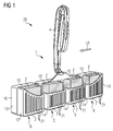
FIG. 1 3 is a perspective view of an exemplary embodiment of a WC active substance dispensing device with an exemplary embodiment of a holding device and active substance blocks arranged therein. -
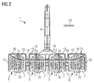
FIG. 2 a rear view of the holding deviceFIG. 1 . -
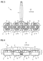
FIG. 3 a frontal view of the holding deviceFIG. 1 and -
FIG. 4 a plan view of the holding deviceFIG. 1 with schematically indicated part of a toilet bowl rim.
Die Figuren werden im Folgenden gemeinsam beschrieben, da sie alle im Wesentlichen lediglich mehrere Ansichten eines Ausführungsbeispiels einer erfindungsgemäßen Haltevorrichtung 1 zeigen. Diese umfasst hier eine Aufhängevorrichtung 4 und vier nach Art einer linearen Kette aneinandergereihte Einzelkörbchen 5, 6 in Form von Einzelkörbchen. Zwei Einzelkörbchen befinden sich an den Enden der Kette und bilden die äußeren Einzelkörbchen 6. Die übrigen beiden sind zwischen letzteren angeordnet und werden somit als innere Einzelkörbchen 5 bezeichnet. Die Aufhängevorrichtung 4 ist hier als biegbarer Bügel ausgebildet, der an eine Toilettenschüssel 3 angeklemmt werden kann. Sie ist über ein Verbindungselement an den beiden mittleren Einzelkörbchen 5 befestigt.The figures will be described jointly below, since they all essentially only show several views of an exemplary embodiment of a
Die Einzelkörbchen 5, 6 sind im Wesentlichen quaderförmig und weisen somit 6 Seitenflächen auf. Alle Seitenflächen sind hier als ebene Wände ausgeführt, die lediglich leichte Abrundungen in Kantenbereichen aufweisen. In einer alternativen Ausführungsform können sie aber auch beispielsweise leicht gekrümmt gefertigt sein. Die Wände umschließen einen ebenfalls quaderförmigen Hohlraum. Zur Definition der Orientierung der Wände wird insbesondere auf
Die Vorderwand 8 hat eine quadratische Fläche, die propellerförmige Sichtöffnungen 9 aufweist. Allerdings können diese Öffnungen in jeder anderen Form gestaltet sein. Entscheidend ist dabei nur, dass durch die Sichtöffnungen der Verbrauchsstand des Wirkstoffs kontrolliert werden kann. Die Deckenwand 10 erstreckt sich von der Vorderwand 8 aus in Richtung Rückwand 11 nur in etwa bis zur Mitte der Einzelkörbchen 5, 6 oberhalb des Bodens 7. Die Rückwand 11 reicht bei den inneren Einzelkörbchen 5 vom Boden 7 aus nach oben zur Deckenwand 10 hin nur bis etwas über die Höhe der Mitte der Vorderwand 8, z. B. in etwa 60% der Höhe. Sie weist hier vertikale Streifen als Wasserauslassöffnungen 21 auf. Genauso gut sind aber auch andere Formen möglich. Die Rückwände der äußeren Einzelkörbchen 6 beginnen auf den Innenseiten genauso wie bei den inneren Einzelkörbchen 5 etwas über der Höhe der Körbchenmitte. Allerdings wird hier die Rückwand 11 von der Innenseite nach außen hin in einem Bogen hinauf bis zur Höhe der Deckenwand 10 geführt. Die inneren Seitenwände 14 erstrecken sich in der vorderen Hälfte der Einzelkörbchen 5, 6 über deren gesamte Höhe. Zur hinteren Hälfte hin ergibt sich eine Stufe in den inneren Seitenwänden 14, sodass sie hier nur noch etwas mehr als die halbe Höhe aufweisen und somit plan an die Rückwand 11 anschließen. Diese Stufe haben die äußeren Seitenwände 13 nicht, sie erstrecken sich vollständig über die gesamte Höhe der äußeren Einzelkörbchen 6, sodass auch sie plan an die hochgezogenen Rückwände der äußeren Einzelkörbchen 6 anschließen. Durch diese Form der Einzelkörbchen 5, 6 ergibt sich im hinteren oberen Bereich jeweils ein Ausschnitt 12, der als großflächiger Wassereinlass dient. Dieser ist bei den inneren Einzelkörbchen 5 größer und erfährt bei den äußeren Einzelkörbchen 6 durch die hochgezogene Rückwand 11 eine Verkleinerung.The
Wie eingangs beschrieben sind die Einzelkörbchen 5, 6 nach Art einer linearen Kette angeordnet. Das heißt, ihre Mittelpunkte befinden sich auf einer Geraden, die eine Längsrichtung LR definiert. Entlang dieser Kette sind benachbarte Einzelkörbchen 5, 6 über Stege 15 verbunden, die sowohl vertikal als auch in Richtung von Vorderwand 8 zu Rückwand 11 mittig in Bezug auf die inneren Seitenwände 14 der Einzelkörbchen 5, 6 angeordnet sind. Das gesamte Ausführungsbeispiel weist eine Spiegelsymmetrie zu einer Mittelebene auf. Diese Mittelebene bezeichnet dabei eine mittig durch die Vorrichtung verlaufende Ebene, die senkrecht auf der Längsrichtung LR steht. Die Ausdehnung der Vorrichtung in der Längsrichtung LR beträgt etwas mehr als 12 cm.As described above, the
Die Einzelkörbchen 5, 6 sind zusätzlich als Halbschalen ausgebildet und an einer Schnittebene in vordere Halbschale 16 und hintere Halbschale 17 zweigeteilt. Dabei erstreckt sich die Schnittebene senkrecht zur Richtung von Vorderwand 8 zu Rückwand 11 und in der Mitte der Einzelkörbchen 5, 6. Die Stege 15 werden ebenfalls durch die Schnittebene halbiert, sodass jede Steghälfte weiterhin benachbarte Einzelkörbchen 5, 6 in Längsrichtung LR miteinander verbindet. Die aus vorderer Halbschale 16 und hinterer Halbschale 17 entstehenden Paare sind im Bereich des Bodens 7 über ein Filmscharnier 18 klappbar verbunden. In geschlossener Position sind sie durch Raststifte 19 befestigt, die im Bereich der Stege in korrespondierende Rastöffnungen eingreifen. Alternativ können auch beispielsweise Spreiznieten oder Druckknöpfe als Befestigung genutzt werden. Dabei können sich alle Raststifte auf einer Seite befinden, die Stifte und Öffnungen können aber auch beispielsweise alternierend angeordnet sein. Vorteilhaft an dieser Bauform ist, dass sie einteilig in einem Spritzgussverfahren gefertigt werden kann. Nach dem Spritzguss kann bei der Herstellung einfach pro Einzelkörbchen 5, 6 ein Wirkstoffformkörper 2 eingelegt werden. Die Halbschalen werden dann zusammengeklappt und über die Arretierungen verschlossen.The
In
Es wird abschließend noch einmal darauf hingewiesen, dass es sich bei den vorhergehend detailliert beschriebenen Vorrichtungen lediglich um Ausführungsbeispiele handelt, welche vom Fachmann in verschiedenster Weise modifiziert werden können, ohne den Bereich der Erfindung zu verlassen. So kann es aus Endverpackungsgründen günstig sein nicht die gesamte Haltevorrichtung einteilig zu fertigen, sondern beispielsweise die Aufhängevorrichtung getrennt herzustellen und nachträglich zum Beispiel vom Verbraucher anbringen zu lassen. Außerdem könnte die Aufhängevorrichtung mit einer Rastung versehen sein, sodass sie an unterschiedliche Toilettenschüsseln angepasst werden kann. Weiterhin schließt die Verwendung der unbestimmten Artikel "ein" bzw. "eine" nicht aus, dass die betreffenden Merkmale auch mehrfach vorhanden sein können.It is finally pointed out once again that the devices described in detail above are only exemplary embodiments which can be modified by the person skilled in many different ways without departing from the scope of the invention. Thus, it may be favorable for Endverpackungsgründen not to produce the entire holding device in one piece, but for example to produce the suspension separately and to attach later, for example, from the consumer. In addition, the suspension could be provided with a detent, so that it can be adapted to different toilet bowls. Furthermore, the use of the indefinite article "on" or "one" does not exclude that the characteristics in question may also be present multiple times.
- 11
- Haltevorrichtungholder
- 22
- WirkstoffformkörperDrug moldings
- 33
- Toilettenschüsseltoilet bowl
- 44
- Aufhängevorrichtungsuspension
- 55
- innere Körbchenkammer, inneres Einzelkörbcheninner cup chamber, inner single basket
- 66
- äußere Körbchenkammer, äußeres Einzelkörbchenouter cup chamber, outer single basket
- 77
- Bodenground
- 88th
- Vorderwandfront wall
- 99
- Sichtöffnungenviewing ports
- 1010
- Deckenwandceiling wall
- 1111
- Rückwandrear wall
- 1212
- Ausschnittneckline
- 1313
- äußere Seitenwändeouter side walls
- 1414
- Seitenwändeside walls
- 1515
- Stegweb
- 1616
- vordere Halbschalefront half shell
- 1717
- hintere Halbschalerear half shell
- 1818
- Filmscharnierfilm hinge
- 1919
- Arretierunglock
- 2020
- WC-WirkstoffabgabevorrichtungWC-drug delivery device
- 2121
- Wasserauslassöffnungwater outlet
- LRLR
- Längsrichtunglongitudinal direction
Claims (10)
wobei die Körbchenkammern (5, 6) in einer Längsrichtung nebeneinander angeordnet sind, sodass sie in einem bestimmungsgemäß in der Toilettenschüssel (3) eingehängten Zustand der Haltevorrichtung (1) im Wesentlichen unterhalb entlang der Unterkante des Rands der Toilettenschüssel (3) nach Art einer geradlinigen Kette nebeneinander positioniert sind,
und wobei die Körbchenkammern (5, 6) jeweils
wherein the cup chambers (5, 6) are arranged side by side in a longitudinal direction so that they are in a state of the holding device (1) hinged in the toilet bowl (3) substantially below the lower edge of the toilet bowl (3) in the manner of a rectilinear one Chain are positioned next to each other,
and wherein the basket chambers (5, 6) respectively
Applications Claiming Priority (1)
| Application Number | Priority Date | Filing Date | Title |
|---|---|---|---|
| DE102015113834.4A DE102015113834B4 (en) | 2015-08-20 | 2015-08-20 | Holding device for holding molded product bodies in a toilet bowl with a suspension device and toilet active substance dispensing device with this holding device |
Publications (1)
| Publication Number | Publication Date |
|---|---|
| EP3133217A1 true EP3133217A1 (en) | 2017-02-22 |
Family
ID=56618033
Family Applications (1)
| Application Number | Title | Priority Date | Filing Date |
|---|---|---|---|
| EP16183401.5A Withdrawn EP3133217A1 (en) | 2015-08-20 | 2016-08-09 | Wc dispensing container |
Country Status (2)
| Country | Link |
|---|---|
| EP (1) | EP3133217A1 (en) |
| DE (1) | DE102015113834B4 (en) |
Cited By (3)
| Publication number | Priority date | Publication date | Assignee | Title |
|---|---|---|---|---|
| IT201800004015A1 (en) * | 2018-03-27 | 2019-09-27 | Bolton Manitoba S P A | Device for sanitary vessels with swirling flow inside the device and relative chemical product tablet |
| WO2022228817A1 (en) * | 2021-04-29 | 2022-11-03 | Henkel Ag & Co. Kgaa | Thermoformed wc basket with flexurally stiff holding device |
| WO2022228816A1 (en) * | 2021-04-29 | 2022-11-03 | Henkel Ag & Co. Kgaa | Wc rim block cage having a clip-like holding device |
Citations (7)
| Publication number | Priority date | Publication date | Assignee | Title |
|---|---|---|---|---|
| WO1999024679A1 (en) * | 1997-11-11 | 1999-05-20 | S.C. Johnson & Son, Inc. | Dispensing device |
| WO2006013322A1 (en) | 2004-08-04 | 2006-02-09 | Reckitt Benckiser Inc | Improved dispensing device |
| USD537914S1 (en) * | 2005-07-15 | 2007-03-06 | Reckitt Benckiser Inc. | Dispensing device |
| US20070214555A1 (en) * | 2006-03-14 | 2007-09-20 | Deoflor S.P.A. | Device for dispensing in the flushing water and/or for mixing with the flushing water detergent and/or sanitizing and/or deodorant products, in toilet bowls or hydraulic and sanitary fixtures in general |
| WO2010018006A1 (en) * | 2008-08-14 | 2010-02-18 | Henkel Ag & Co. Kgaa | Wc-balls with flushing water distributing element |
| WO2015048657A1 (en) | 2013-09-30 | 2015-04-02 | S. C. Johnson & Son, Inc. | Lavatory bowl rim block holder with pivoting hook |
| US20150167282A1 (en) | 2012-08-22 | 2015-06-18 | Henkel Ag & Co. Kgaa | Toilet cleaner with variable product dispension |
-
2015
- 2015-08-20 DE DE102015113834.4A patent/DE102015113834B4/en active Active
-
2016
- 2016-08-09 EP EP16183401.5A patent/EP3133217A1/en not_active Withdrawn
Patent Citations (8)
| Publication number | Priority date | Publication date | Assignee | Title |
|---|---|---|---|---|
| WO1999024679A1 (en) * | 1997-11-11 | 1999-05-20 | S.C. Johnson & Son, Inc. | Dispensing device |
| WO2006013322A1 (en) | 2004-08-04 | 2006-02-09 | Reckitt Benckiser Inc | Improved dispensing device |
| USD537914S1 (en) * | 2005-07-15 | 2007-03-06 | Reckitt Benckiser Inc. | Dispensing device |
| US20070214555A1 (en) * | 2006-03-14 | 2007-09-20 | Deoflor S.P.A. | Device for dispensing in the flushing water and/or for mixing with the flushing water detergent and/or sanitizing and/or deodorant products, in toilet bowls or hydraulic and sanitary fixtures in general |
| WO2010018006A1 (en) * | 2008-08-14 | 2010-02-18 | Henkel Ag & Co. Kgaa | Wc-balls with flushing water distributing element |
| DE102008037723A1 (en) | 2008-08-14 | 2010-02-25 | Henkel Ag & Co. Kgaa | Toilet basket with Spülwasserverteilelement |
| US20150167282A1 (en) | 2012-08-22 | 2015-06-18 | Henkel Ag & Co. Kgaa | Toilet cleaner with variable product dispension |
| WO2015048657A1 (en) | 2013-09-30 | 2015-04-02 | S. C. Johnson & Son, Inc. | Lavatory bowl rim block holder with pivoting hook |
Cited By (4)
| Publication number | Priority date | Publication date | Assignee | Title |
|---|---|---|---|---|
| IT201800004015A1 (en) * | 2018-03-27 | 2019-09-27 | Bolton Manitoba S P A | Device for sanitary vessels with swirling flow inside the device and relative chemical product tablet |
| WO2019186247A1 (en) * | 2018-03-27 | 2019-10-03 | Bolton Manitoba S.P.A. | Device for sanitary fittings bowls with vortical flow inside the device and related tablet of chemical product |
| WO2022228817A1 (en) * | 2021-04-29 | 2022-11-03 | Henkel Ag & Co. Kgaa | Thermoformed wc basket with flexurally stiff holding device |
| WO2022228816A1 (en) * | 2021-04-29 | 2022-11-03 | Henkel Ag & Co. Kgaa | Wc rim block cage having a clip-like holding device |
Also Published As
| Publication number | Publication date |
|---|---|
| DE102015113834A1 (en) | 2017-02-23 |
| DE102015113834B4 (en) | 2017-08-24 |
Similar Documents
| Publication | Publication Date | Title |
|---|---|---|
| EP3002375B1 (en) | Rim block with flushing water distributing element | |
| EP2620489B1 (en) | Active agent dispensing device and method for manufacturing an active agent dispensing device | |
| DE102013105316A1 (en) | Holding device and flushing device for mounting in a toilet bowl and producing the same flushing device | |
| EP1799921B1 (en) | Toilet cover with dosing dispenser | |
| WO2014029510A1 (en) | Toilet cleaner with variable product dispension | |
| DE102015113834B4 (en) | Holding device for holding molded product bodies in a toilet bowl with a suspension device and toilet active substance dispensing device with this holding device | |
| DE19720393A1 (en) | Device for cleaning and refreshing toilet bowls | |
| DE102008003359A1 (en) | Dispensing device for dispensing at least one active substance fluid into the rinsing water of a toilet bowl and for scenting the environment | |
| DE3304027A1 (en) | PASSIVE DELIVERY DEVICE | |
| DE102005061974B3 (en) | Sanitary water outlet fitting e.g. bath tub filter, has water outlet housing with oblong running supply channels vertical to water outlet stream and supply channels regenerates in funnel shaped cross-flow direction | |
| DE202018006705U1 (en) | flush toilet | |
| EP3170940A1 (en) | Shower wc with water heater | |
| EP2620490B1 (en) | Active agent dispensing device and method for manufacturing an active agent dispensing device | |
| EP0446795A1 (en) | Dosage-device for a medium which is to be activated by water | |
| DE19945598B4 (en) | Dispensing device for the delivery of an active substance | |
| DE202013102261U1 (en) | Holding device and flushing device for attachment in a toilet bowl | |
| WO2019081231A1 (en) | Wc basket and wc flusher system | |
| DE102011001049A1 (en) | Device for dispensing agent for cleaning or fragrancing or treatment of sanitary facilities in rinse water from toilet bowl, has container provided with dilution chamber, in which rinsing water is accommodated | |
| EP3628726A1 (en) | Toilet bowl deodorizer block comprising two different compositions | |
| EP1659227A1 (en) | Pressure flushing device | |
| DE60114106T2 (en) | Cleaning and deodorizing device for a toilet bowl | |
| CH645689A5 (en) | Container which is to be arranged in the WC bowl and has cleaning agents and fragrancing means and, in addition, deodorisers and/or disinfecting agents in element form | |
| DE69822754T2 (en) | Refrigerator with cells for making ice cubes | |
| DE3738554A1 (en) | WC MACHINE FOR DELIVERING AN ACTIVE SUBSTANCE SOLUTION AFTER EVERY TOILET RINSE | |
| EP1605807B1 (en) | Device for dispensing at least one water-soluble active substance onto a cleaning brush |
Legal Events
| Date | Code | Title | Description |
|---|---|---|---|
| PUAI | Public reference made under article 153(3) epc to a published international application that has entered the european phase |
Free format text: ORIGINAL CODE: 0009012 |
|
| AK | Designated contracting states |
Kind code of ref document: A1 Designated state(s): AL AT BE BG CH CY CZ DE DK EE ES FI FR GB GR HR HU IE IS IT LI LT LU LV MC MK MT NL NO PL PT RO RS SE SI SK SM TR |
|
| AX | Request for extension of the european patent |
Extension state: BA ME |
|
| 17P | Request for examination filed |
Effective date: 20170811 |
|
| RBV | Designated contracting states (corrected) |
Designated state(s): AL AT BE BG CH CY CZ DE DK EE ES FI FR GB GR HR HU IE IS IT LI LT LU LV MC MK MT NL NO PL PT RO RS SE SI SK SM TR |
|
| 17Q | First examination report despatched |
Effective date: 20180109 |
|
| GRAP | Despatch of communication of intention to grant a patent |
Free format text: ORIGINAL CODE: EPIDOSNIGR1 |
|
| INTG | Intention to grant announced |
Effective date: 20191111 |
|
| GRAJ | Information related to disapproval of communication of intention to grant by the applicant or resumption of examination proceedings by the epo deleted |
Free format text: ORIGINAL CODE: EPIDOSDIGR1 |
|
| INTC | Intention to grant announced (deleted) | ||
| GRAP | Despatch of communication of intention to grant a patent |
Free format text: ORIGINAL CODE: EPIDOSNIGR1 |
|
| STAA | Information on the status of an ep patent application or granted ep patent |
Free format text: STATUS: GRANT OF PATENT IS INTENDED |
|
| INTG | Intention to grant announced |
Effective date: 20200512 |
|
| STAA | Information on the status of an ep patent application or granted ep patent |
Free format text: STATUS: THE APPLICATION IS DEEMED TO BE WITHDRAWN |
|
| 18D | Application deemed to be withdrawn |
Effective date: 20200923 |