EP3132908B1 - Vorrichtung zur demontage des dorns herstellung einer verbundstoffstruktur - Google Patents
Vorrichtung zur demontage des dorns herstellung einer verbundstoffstruktur Download PDFInfo
- Publication number
- EP3132908B1 EP3132908B1 EP16001805.7A EP16001805A EP3132908B1 EP 3132908 B1 EP3132908 B1 EP 3132908B1 EP 16001805 A EP16001805 A EP 16001805A EP 3132908 B1 EP3132908 B1 EP 3132908B1
- Authority
- EP
- European Patent Office
- Prior art keywords
- segment
- support
- mandrel
- section
- segments
- Prior art date
- Legal status (The legal status is an assumption and is not a legal conclusion. Google has not performed a legal analysis and makes no representation as to the accuracy of the status listed.)
- Active
Links
Images







Classifications
-
- B—PERFORMING OPERATIONS; TRANSPORTING
- B29—WORKING OF PLASTICS; WORKING OF SUBSTANCES IN A PLASTIC STATE IN GENERAL
- B29C—SHAPING OR JOINING OF PLASTICS; SHAPING OF MATERIAL IN A PLASTIC STATE, NOT OTHERWISE PROVIDED FOR; AFTER-TREATMENT OF THE SHAPED PRODUCTS, e.g. REPAIRING
- B29C33/00—Moulds or cores; Details thereof or accessories therefor
- B29C33/44—Moulds or cores; Details thereof or accessories therefor with means for, or specially constructed to facilitate, the removal of articles, e.g. of undercut articles
- B29C33/48—Moulds or cores; Details thereof or accessories therefor with means for, or specially constructed to facilitate, the removal of articles, e.g. of undercut articles with means for collapsing or disassembling
- B29C33/485—Moulds or cores; Details thereof or accessories therefor with means for, or specially constructed to facilitate, the removal of articles, e.g. of undercut articles with means for collapsing or disassembling cores or mandrels
-
- B—PERFORMING OPERATIONS; TRANSPORTING
- B29—WORKING OF PLASTICS; WORKING OF SUBSTANCES IN A PLASTIC STATE IN GENERAL
- B29C—SHAPING OR JOINING OF PLASTICS; SHAPING OF MATERIAL IN A PLASTIC STATE, NOT OTHERWISE PROVIDED FOR; AFTER-TREATMENT OF THE SHAPED PRODUCTS, e.g. REPAIRING
- B29C33/00—Moulds or cores; Details thereof or accessories therefor
- B29C33/38—Moulds or cores; Details thereof or accessories therefor characterised by the material or the manufacturing process
- B29C33/3842—Manufacturing moulds, e.g. shaping the mould surface by machining
-
- B—PERFORMING OPERATIONS; TRANSPORTING
- B64—AIRCRAFT; AVIATION; COSMONAUTICS
- B64F—GROUND OR AIRCRAFT-CARRIER-DECK INSTALLATIONS SPECIALLY ADAPTED FOR USE IN CONNECTION WITH AIRCRAFT; DESIGNING, MANUFACTURING, ASSEMBLING, CLEANING, MAINTAINING OR REPAIRING AIRCRAFT, NOT OTHERWISE PROVIDED FOR; HANDLING, TRANSPORTING, TESTING OR INSPECTING AIRCRAFT COMPONENTS, NOT OTHERWISE PROVIDED FOR
- B64F5/00—Designing, manufacturing, assembling, cleaning, maintaining or repairing aircraft, not otherwise provided for; Handling, transporting, testing or inspecting aircraft components, not otherwise provided for
- B64F5/10—Manufacturing or assembling aircraft, e.g. jigs therefor
-
- B—PERFORMING OPERATIONS; TRANSPORTING
- B29—WORKING OF PLASTICS; WORKING OF SUBSTANCES IN A PLASTIC STATE IN GENERAL
- B29L—INDEXING SCHEME ASSOCIATED WITH SUBCLASS B29C, RELATING TO PARTICULAR ARTICLES
- B29L2031/00—Other particular articles
- B29L2031/30—Vehicles, e.g. ships or aircraft, or body parts thereof
- B29L2031/3076—Aircrafts
- B29L2031/3082—Fuselages
-
- Y—GENERAL TAGGING OF NEW TECHNOLOGICAL DEVELOPMENTS; GENERAL TAGGING OF CROSS-SECTIONAL TECHNOLOGIES SPANNING OVER SEVERAL SECTIONS OF THE IPC; TECHNICAL SUBJECTS COVERED BY FORMER USPC CROSS-REFERENCE ART COLLECTIONS [XRACs] AND DIGESTS
- Y10—TECHNICAL SUBJECTS COVERED BY FORMER USPC
- Y10T—TECHNICAL SUBJECTS COVERED BY FORMER US CLASSIFICATION
- Y10T29/00—Metal working
- Y10T29/49—Method of mechanical manufacture
- Y10T29/49815—Disassembling
-
- Y—GENERAL TAGGING OF NEW TECHNOLOGICAL DEVELOPMENTS; GENERAL TAGGING OF CROSS-SECTIONAL TECHNOLOGIES SPANNING OVER SEVERAL SECTIONS OF THE IPC; TECHNICAL SUBJECTS COVERED BY FORMER USPC CROSS-REFERENCE ART COLLECTIONS [XRACs] AND DIGESTS
- Y10—TECHNICAL SUBJECTS COVERED BY FORMER USPC
- Y10T—TECHNICAL SUBJECTS COVERED BY FORMER US CLASSIFICATION
- Y10T29/00—Metal working
- Y10T29/53—Means to assemble or disassemble
- Y10T29/53539—Means to assemble or disassemble including work conveyor
-
- Y—GENERAL TAGGING OF NEW TECHNOLOGICAL DEVELOPMENTS; GENERAL TAGGING OF CROSS-SECTIONAL TECHNOLOGIES SPANNING OVER SEVERAL SECTIONS OF THE IPC; TECHNICAL SUBJECTS COVERED BY FORMER USPC CROSS-REFERENCE ART COLLECTIONS [XRACs] AND DIGESTS
- Y10—TECHNICAL SUBJECTS COVERED BY FORMER USPC
- Y10T—TECHNICAL SUBJECTS COVERED BY FORMER US CLASSIFICATION
- Y10T29/00—Metal working
- Y10T29/53—Means to assemble or disassemble
- Y10T29/53983—Work-supported apparatus
Definitions
- the present invention relates to a disassembling apparatus of a mandrel suitable for use in a disassembling method of a mandrel which is used for manufacturing a composite material structure using a fiber-reinforced resin composite material and is constructed of a plurality of segments assembled in a tubular shape.
- the present invention relates to a disassembling apparatus of a mandrel suitable for use in a disassembling method of a mandrel suitably used for manufacturing a huge composite material structure for use as a fuselage of an aircraft, etc.
- the mold supported and constructed in the cylindrical shape is transported to a skin laminating station by a tool support structure.
- the mold is rotated along the longitudinal axis, to laminate fiber tow (bundle of untwisted continuous filaments which is impregnated with thermosetting resin) by a fiber placement machine, thereby forming a laminate (corresponding to skin) on the outer periphery of the mold.
- a disassembling apparatus of a mandrel suitable for use in a disassembling method of a mandrel, which disassembles the mandrel including a plurality of segments assembled in a tubular shape, into individual segments, the plurality of segments having a substantially rectangular shape and being parts into which the mandrel is divided along a center axis direction, the mandrel being in a state in which the segments are joined together between a pair of support rings facing each other, the segments are each fastened to the support rings to form the tubular shape, and the mandrel is adhesively attached with a composite material structure on an outer peripheral surface thereof; the disassembling method comprising: a rotation step of rotating the pair of support rings along with the mandrel to position a segment which is a detached target to an uppermost portion; and a segment detaching step of detaching the segment which is the detached target positioned at the uppermost portion, from the pair of support rings; wherein in the segment de
- the segment which is the detached target when the segment which is the detached target, is detached from the support ring, the segment is positioned at the uppermost portion of the support ring.
- the segment When the segment is moved vertically downward from the uppermost portion, the detached segment is moved to inside of the mandrel. Therefore, the segment can be detached without substantially affecting the composite material structure fanned on the outer peripheral surface of the mandrel.
- the segment Inside of the mandrel, the segment is positioned between the pair of support rings. By horizontally moving the segment through the hollow space of the support rings, the segment can be carried out easily from between the support rings.
- the segment which is the detached target is moved to the uppermost portion which is positioned between the pair of support rings.
- the segment By horizontally moving the segment through the hollow space of the support rings, the segment can be carried out easily from between the support rings.
- the segment which is the detached target is moved to the uppermost portion which is a determined location, by rotating the support rings.
- the segment which is the detached target is moved only in the vertical direction. This makes it possible to easily detach all of the plurality of segments in the same step.
- the disassembling apparatus is, preferably, suitable for use in a disassembling method of a mandrel wherein in the segment detaching step, a segment joining/guide mechanism provided between the segment which is the detached target and a segment adjacent to the segment which is the detached target, guides the segment being moved downward, along the vertical direction.
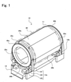
- a carriage 13 is configured to carry the cradles 12a, 12b, the support rings 40a, 40b, and the mandrel 11.
- the carriage 13 has a rectangular flat shape, and is provided with a plurality of wheels on the lower surface of the carriage 13, although not shown Fig. 1 .
- the carriage 13 is able to carry the cradles 12a, 12b, the support rings 40a, 40b, and the mandrel 11, with the mold 10 placed thereon.
- the carriage 13 has an upper surface having a greater area to correspond to the dimension (axial length of a cylinder and a diameter of a cylinder) of the mandrel 11.
- the cradles 12a, 12b are not in contact with the carriage 13 and stand for themselves on a floor surface such that the height of the support rings 40a, 40b which face each other is horizontally adjustable.
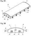
- the normal-line direction of the side surfaces 22 of the first segment 20 is inclined in the upward direction toward the obverse surface 21 (arrow Ar2 direction of Fig. 2B ).
- the fact that the normal-line direction of the side surfaces 22 of the first segment 20 is inclined in the upward direction means that the side surfaces 22 are inclined to face in the upward direction.
- the side surfaces 22 are inclined such that an edge of the side surface 22 on the reverse side is outward relative to an edge thereof on the obverse side.
- the inclined side surfaces 22 form "draft" in the both side surfaces 22 of the first segment 20. Therefore, the first segment 20 is drawn out easily from between the second segments 30, and thus, the mandrel 11 is disassembled easily.
- the male joining members 261, the joining wedge members, and the female joining members (described later) provided on the side surface of the second segment 30 constitute a segment joining/retaining mechanism.
- the outer peripheral female guide members 262 and outer peripheral male guide members (described later) provided on the side surface of the second segment 30 constitute a segment joining/guide mechanism.
- the inner peripheral male guide members and inner peripheral female guide members (described later) provided on the side surface of the second segment 30 constitute a segment joining/guide mechanism.
- Fig. 2B to make clear the positional relationship between the side surfaces 22, the male joining members 261, the outer peripheral female guide members 262, the inner peripheral male guide members, and the joining wedge members are not shown.
- the second segment 30 has a door frame portion 15a and window frame portions 15b.
- the door frame portion 15a corresponds to a door in the OPB formed using the mold 10 of the present embodiment
- the window frame portions 15b correspond to windows in the OPB.
- the door frame portion 15a and the window frame portions 15b are concave-convex portions used for cutting and perforation in a trimming process.
- the door frame portion 15a and the window frame portions 15b are formed on the obverse surface 31 of the second segment 30, the present invention is not limited to this.
- the door frame portion 15a and the window frame portions 15b may be formed on the obverse surface 21 of the first segment 20 or on both of the first segment 20 and the second segment 30.
- the stringer is attachable on the obverse surface 31 of the second segment 30.
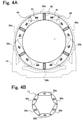
- the mandrel 11 is constructed and retained in such a manner that the segments 20, 30 are fastened to the support ring 40 having the above configuration, and has a structure in which the first segment 20 and the second segment 30 are arranged alternately as shown in Fig. 4B .
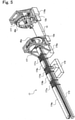
- Fig. 5 is a perspective view showing an example of the overall configuration of the precision rail.
- Fig. 6A is a schematic plan view showing a state in which the segment is placed on the precision rail of Fig. 5
- Fig. 6B is a block diagram showing a schematic configuration of the ring rotation drive section included in the precision rail of Fig. 5 .
- the support rings 40a, 40b are supported by the cradles 12a, 12b, respectively and by the rail support work tables 176a, 176b, respectively.
- the cradle 12a (12b) supports the support ring 40a (40b) from below by arms sections 121 at least two locations sandwiching a vertical line passing through a center axis of the support ring 40a (40b) and is applied with a rotational force from the ring rotation drive section via the support rollers 123 (see Fig. 1 ).
- the rail support work tables 176a, 176b restrict axial movement of the support rings 40a, 40b, on the upper portions of the support rings 40a, 40b (see Fig. 5 ). In this way, since the support rings 40a, 40b are supported at the upper portion and the lower portion, the support rings 40a, 40b can be rotated while preventing them from falling.
- the movement of the rail body 173 is defined as follows. When the rail body 173 is inserted into the hollow space of the support rings 40a, 40b or the inside of the mandrel 11, this movement is referred to as “forward movement,” while when the rail body 173 is drawn out of the hollow space of the support rings 40a, 40b or the inside of the mandrel 11, this movement is referred to as “backward movement.”
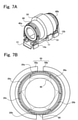
- Fig. 7A is a perspective view schematically showing a state in which an outer ring 50 used in the present embodiment is mounted to the outer periphery of the molded product 80
- Fig. 7B is a plan view schematically showing a state in which the outer ring 50 of Fig. 7A is mounted to the molded product 80.
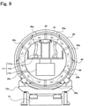
- Fig. 9 is a schematic view showing a state in which the jack section 171a (and jack section 171b) is moved up and placed at a reverse side of a first segment 20a of #1, to detach the first segment 20a from a second segment 30c of #6 adjacent to the first segment 20a, a second segment 30a of #2 adjacent to the first segment 20a, and the support rings 40a, 40b.
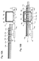
- Figs. 10A and 10B are side views of the precision rail 17 showing the operation of the precision rail 17, which is performed when the first segment 20a is detached.
- Figs. 11A to 11C are side views of the precision rail 17 showing the operation of the precision rail 17, which follows the operation of Fig. 10B .
- the cradle 12a mounted to the carriage 13 supports the support ring 40a and the support ring 40b which is not shown, such that the support rings 40a, 40b stand vertically, and the mandrel 11 is retained between the support rings 40a, 40b (step P01 shown in Fig. 8 , mold installation step).
- the precision rail 17 is placed in a location in the hollow space of the mandrel 11 and the support rings 40a, 40b and between the support rings 40a, 40b facing each other.
- Fig. 11A the jack sections 171a, 171b stop in contact with the reverse side of the first segment 20a.
- the state shown in Fig. 11A corresponds to the state shown in Fig. 9 .
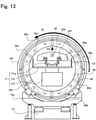
- the guide mechanisms guide the first segment 20a to cause it to move downward in a proper direction and is detached from the support rings 40a, 40b as shown in Fig. 11B and Fig. 13 without affecting the components (support rings 40a, 40b, and adjacent second segments 30c, 30a) in the vicinity of the first segment 20a (step P03-2 in Fig. 8 , first segment detaching step).
- the operation for adjusting the positions of the portions in the vicinity of the four corners of the first segment 20a, when the first segment 20a is moved downward is referred to as "four-corner position adjustment operation).
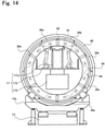
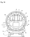
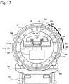
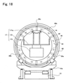
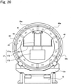
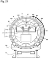
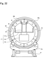
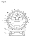
- Figs. 18 to 23 are schematic views showing a state in which the jack section 171a is moved up or downward when the second segment 30c of #6, the second segment 30b of #2, or the second segment 30c of #4, is detached from the support rings 40a, 40b.
Landscapes
- Engineering & Computer Science (AREA)
- Manufacturing & Machinery (AREA)
- Mechanical Engineering (AREA)
- Transportation (AREA)
- Aviation & Aerospace Engineering (AREA)
- Moulding By Coating Moulds (AREA)
- Moulds For Moulding Plastics Or The Like (AREA)
Claims (8)
- Vorrichtung zur Demontage eines Dorns (11), die zur Verwendung im Rahmen eines Demontageverfahrens eines Dorns (11) geeignet ist, bei dem ein eine Vielzahl von im montierten Zustand eine Rohrform bildenden Segmenten (20, 30, 20a, 30a, 20b, 30b, 20c, 30c) aufweisender Dorn (11) in einzelne Segmente (20, 30, 20a, 30a, 20b, 30b, 20c, 30c) demontiert wird, wobei die Vielzahl von Segmenten (20, 30, 20a, 30a, 20b, 30b, 20c, 30c) eine im Wesentlichen rechteckige Form aufweist und es sich dabei um Teile handelt, in die der Dorn (11) entlang einer Mittelachsenrichtung geteilt ist,wobei sich der Dorn (11) in einem Zustand befindet, in dem die Segmente (20, 30, 20a, 30a, 20b, 30b, 20c, 30c) zwischen einem Paar von einander zugewandten Stützringen (40, 40a, 40b) miteinander verbunden sind, wobei die Segmente (20, 30, 20a, 30a 20b, 30b, 20c, 30c) jeweils an den Stützringen (40, 40a, 40b) befestigt sind, um die Rohrform zu bilden, und der Dorn (11) mit einer Verbundmaterialstruktur (80) an einer äußeren Umfangsfläche davon angeklebt ist;wobei das Demontageverfahren Folgendes umfasst:einen Drehschritt zum Drehen des Paares von Stützringen (40, 40a, 40b) zusammen mit dem Dorn (11), um ein Segment (20, 30, 20a, 30a, 20b, 30b, 20c, 30c), bei dem es sich um ein loszulösendes Ziel handelt, an einem obersten Abschnitt zu positionieren; undeinen Segmentloslösungsschritt zum Loslösen des Segments (20, 30, 20a, 30a, 20b, 30b, 20c, 30c), bei dem es sich um das an dem obersten Abschnitt positionierte loszulösende Ziel handelt, von dem Paar von Stützringen (40, 40a, 40b);wobei in dem Segmentloslösungsschritt das Segment (20, 30, 20a, 30a, 20b, 30b, 20c, 30c), bei dem es sich um das loszulösende Ziel handelt, in einer vertikal nach unten gerichteten Richtung zu einer Position innerhalb des Dorns (11) zwischen dem Paar von Stützringen (40, 40a, 40b) bewegt wird und zwischen dem Paar von Stützringen (40, 40a, 40b) herausgetragen wird,wobei die Demontagevorrichtung Folgendes umfasst:einen Schienenkörper (173), der in einen Hohlraum des Paares von Stützringen (40, 40a, 40b) eingesetzt ist;einen Förderabschnitt (174a, 174b, 174c), der an dem Schienenkörper (173) vorgesehen und konfiguriert ist, um das Segment (20, 30, 20a, 30a, 20b, 30b, 20c, 30c) von einem hinteren Ende des Schienenkörpers (173) zu einem Spitzenende davon und von dem Spitzenende zu dem hinteren Ende des Schienenkörpers (173) horizontal zu bewegen; undeinen Heberabschnitt (171a, 171b, 171c), der an dem Schienenkörper (173) vorgesehen und konfiguriert ist, um das von dem Förderabschnitt (174a, 174b, 174c) bewegte Segment (20, 30, 20a, 30a, 20b, 30b, 20c, 30c) anzuheben und das Segment (20, 30,20a, 30a, 20b, 30b, 20c, 30c) nach unten zu bewegen, um es auf dem Förderabschnitt (174a, 174b, 174c) entlang einer vertikalen Richtung zu platzieren;wobei der Heberabschnitt (171a, 171b, 171c) Segmentstützelemente (171a-1, 171a-2, 171b-1, 171b-2) zum Stützen zumindest von Abschnitten in der Nähe der vier Ecken des Segments (20, 30, 20a, 30a, 20b, 30b, 20c, 30c) mit der im Wesentlichen rechteckigen Form umfasst, dadurch gekennzeichnet, dass der Heberabschnitt (171a, 171b, 171c) angepasst ist, um die Abschnitte unabhängig voneinander entlang der vertikalen Richtung zwischen den Stützringen (40, 40a, 40b) zu verschieben in einem Zustand, in dem der Schienenkörper (173) in den Hohlraum der Stützringe eingesetzt ist.
- Vorrichtung nach Anspruch 1, die ferner Folgendes umfasst:einen Schienenbewegungsstütztisch (175);einen ersten und einen zweiten Schienenstützarbeitstisch (176a, 176b), die so positioniert sind, dass sie einander zugewandt sind;oberseitige Arbeitstische (177), die jeweils auf den Schienenstützarbeitstischen (176a, 176b) vorgesehen sind;wobei es sich bei dem Schienenkörper (173) um ein einzelnes Schienenelement handelt, das derart auf dem Schienenbewegungsstütztisch (175) und dem ersten Schienenstützarbeitstisch (176a) gestützt wird, dass der Schienenkörper (173) entlang seiner Längsrichtung beweglich ist;einen klammer- oder scherenförmigen Bewegungsstützmechanismus, der auf einer Basis unter dem ersten Schienenstützarbeitstisch (176a) vorgesehen ist, um den Schienenkörper (173) derart zu stützen, dass der Schienenkörper (173) beweglich ist, wobei der Bewegungsstützmechanismus nach rechts und links geöffnet wird, wenn der Schienenkörper (173) sich bewegt, und der Bewegungsstützmechanismus geschlossen wird, um den Schienenkörper (173) während eines angehaltenen Zustands des Schienenkörpers (173) zu umschließen;einen unterhalb der Schienenstützarbeitstische (176a, 176b) vorgesehenen Ringdrehantriebsabschnitt (16) zum Drehen der Stützringe (40a, 40b;einen Anschlagstützmechanismus, der unter dem zweiten Schienenstützarbeitstisch (176b) vorgesehen ist, um den Schienenkörper (173) derart zu stützen, dass der Schienenkörper (173) sich nicht über die Position des zweiten Schienenstützarbeitstisches (176b) hinaus bewegt;wobei der Ringdrehantriebsabschnitt (16) Folgendes umfasst: ein Antriebszahnrad (161), das mit einem am Außenumfang des Stützrings (40a, 40b) vorgesehenen Drehzahnradabschnitt (45) kämmt, eine Antriebsquelle (162), die einen Motor und ein Getriebe enthält und das Antriebszahnrad (161) dreht, einen Positionserfassungsabschnitt (163), der erfasst, ob das Segment (20, 30), bei dem es sich um das loszulösende Ziel handelt, am obersten Abschnitt des Stützrings (40) positioniert ist oder nicht, und einen Drehsteuerabschnitt (164) in Form eines Prozessors zum Steuern des Antriebszahnrads (161), der Antriebsquelle (162) und des Positionserfassungsabschnitts (163).
- Vorrichtung nach Anspruch 2, wobei der Positionserfassungsabschnitt (163) angepasst ist, um einen erfassten Abschnitt, der auf dem Stützring (40, 40a, 40b) vorgesehen ist, zu erfassen.
- Vorrichtung nach einem der vorhergehenden Ansprüche, umfassend drei Förderabschnitte (174a, 174b, 174c) und drei Heberabschnitte (171a, 171b, 171c), die auf der oberen Fläche des Schienenkörpers (173) vorgesehen sind und derart angeordnet sind, dass ein erster Förderabschnitt (174a), ein erster Heberabschnitt (171a), ein zweiter Förderabschnitt (174b), ein zweiter Heberabschnitt (171b), ein dritter Förderabschnitt (174c) und ein dritter Heberabschnitt (171c) in dieser Reihenfolge von einer hinteren Endseite des Schienenkörpers (173) ausgerichtet sind.
- Vorrichtung nach Anspruch 4, wobei der erste, der zweite und der dritte Hebeabschnitt (171a, 171b, 171c) im Wesentlichen gleiche Abmessungen und im Wesentlichen die gleiche Konfiguration aufweisen und jeweils so konfiguriert sind, dass sie ein darauf platziertes Objekt in einer Aufwärtsrichtung bis zu einer Position oberhalb der Stützringe (40a, 40b) bewegen, und wobei der erste Förderabschnitt (174a) an der hintersten Seite eine größere Länge in einer Förderrichtung aufweist als der zweite und dritte Förderabschnitt (174b, 174c) und als eine Längsabmessung jedes der Segmente (20, 30), und er so konfiguriert ist, dass jedes der darauf platzierten Segmente (20, 30) horizontal in Richtung des Spitzenendes des Schienenkörpers (173) zu einer Position befördert wird, die die oberen Oberflächen des ersten Heberabschnitts (171a), des zweiten Förderabschnitts (174b) und des zweiten Heberabschnitts (171b) bedeckt.
- Vorrichtung nach einem der Ansprüche 1 bis 4, wobei vier Heberabschnitte vorgesehen sind, um jeweils die Abschnitte in der Nähe der vier Ecken des Segments (20, 20a, 20b, 20c, 30, 30a, 30b, 30c) zu stützen.
- Vorrichtung nach einem der Ansprüche 1 bis 4, wobei nur ein Heberabschnitt vorgesehen ist, um alle Abschnitte in der Nähe der vier Ecken des Segments (20, 20a, 20b, 20c, 30, 30a, 30b, 30c) zu stützen.
- Vorrichtung nach einem der vorhergehenden Ansprüche, wobei jeder der Heberabschnitte (171a, 171b, 171c) ein Paar Stützstangenelemente (171a-1, 171a-2, 171b-1, 171b-2) als Segmentstützelemente aufweist, wobei die Stützstangenelemente (171a-1, 171a-2, 171b-1, 171b-2) derart auf der oberen Fläche des Schienenkörpers (173) vorgesehen sind, dass sie parallel zur Längsrichtung des Schienenkörpers (173) sind und einander zugewandt sind, um einem Mittelabschnitt in einer Querschnittsrichtung des Schienenkörpers einzuschließen.
Applications Claiming Priority (3)
| Application Number | Priority Date | Filing Date | Title |
|---|---|---|---|
| JP2009295577A JP5576652B2 (ja) | 2009-12-25 | 2009-12-25 | 複合材料構造物製造用マンドレルの分解方法およびマンドレルの分解装置 |
| EP10838939.6A EP2517859B1 (de) | 2009-12-25 | 2010-12-21 | Demontageverfahren eines bei der herstellung von einer verbundmaterialstruktur verwendeten dorns |
| PCT/JP2010/007393 WO2011077700A1 (ja) | 2009-12-25 | 2010-12-21 | 複合材料構造物製造用マンドレルの分解方法およびマンドレルの分解装置 |
Related Parent Applications (2)
| Application Number | Title | Priority Date | Filing Date |
|---|---|---|---|
| EP10838939.6A Division EP2517859B1 (de) | 2009-12-25 | 2010-12-21 | Demontageverfahren eines bei der herstellung von einer verbundmaterialstruktur verwendeten dorns |
| EP10838939.6A Division-Into EP2517859B1 (de) | 2009-12-25 | 2010-12-21 | Demontageverfahren eines bei der herstellung von einer verbundmaterialstruktur verwendeten dorns |
Publications (3)
| Publication Number | Publication Date |
|---|---|
| EP3132908A2 EP3132908A2 (de) | 2017-02-22 |
| EP3132908A3 EP3132908A3 (de) | 2017-04-19 |
| EP3132908B1 true EP3132908B1 (de) | 2022-03-02 |
Family
ID=44195254
Family Applications (2)
| Application Number | Title | Priority Date | Filing Date |
|---|---|---|---|
| EP10838939.6A Active EP2517859B1 (de) | 2009-12-25 | 2010-12-21 | Demontageverfahren eines bei der herstellung von einer verbundmaterialstruktur verwendeten dorns |
| EP16001805.7A Active EP3132908B1 (de) | 2009-12-25 | 2010-12-21 | Vorrichtung zur demontage des dorns herstellung einer verbundstoffstruktur |
Family Applications Before (1)
| Application Number | Title | Priority Date | Filing Date |
|---|---|---|---|
| EP10838939.6A Active EP2517859B1 (de) | 2009-12-25 | 2010-12-21 | Demontageverfahren eines bei der herstellung von einer verbundmaterialstruktur verwendeten dorns |
Country Status (4)
| Country | Link |
|---|---|
| US (2) | US9021678B2 (de) |
| EP (2) | EP2517859B1 (de) |
| JP (1) | JP5576652B2 (de) |
| WO (1) | WO2011077700A1 (de) |
Families Citing this family (10)
| Publication number | Priority date | Publication date | Assignee | Title |
|---|---|---|---|---|
| ITTO20120286A1 (it) * | 2012-03-30 | 2013-10-01 | Alenia Aermacchi Spa | Sistema di vincolo settori appartenenti ad un dispositivo per la realizzazione di una sezione di fusoliera di un aereo |
| ITTO20120287A1 (it) * | 2012-03-30 | 2013-10-01 | Alenia Aermacchi Spa | Sistema posizionamento settori appartenenti ad un dispositivo per la realizzazione di una sezione di fusoliera di un aereo |
| JP6256989B2 (ja) * | 2013-05-21 | 2018-01-10 | 三井住友建設株式会社 | 既設洞道の更新方法 |
| US9597843B2 (en) * | 2014-05-15 | 2017-03-21 | The Boeing Company | Method and apparatus for layup tooling |
| US10207431B2 (en) * | 2016-01-27 | 2019-02-19 | The Boeing Company | System, method, and tool assembly for removing a component from a mandrel assembly |
| US10344906B2 (en) * | 2017-01-27 | 2019-07-09 | The Boeing Company | Isolated human work platform for stabilized positioning of collaborative robotics |
| US11407185B2 (en) * | 2017-12-18 | 2022-08-09 | The Boeing Company | Layup tools that facilitate transfer of laminates to cure tools |
| US10520933B2 (en) * | 2018-04-13 | 2019-12-31 | The Boeing Company | System and method for removing a workpiece from a manufacturing fixture |
| IT202200007511A1 (it) * | 2022-04-14 | 2023-10-14 | Leonardo Spa | Attrezzatura e procedimento per la realizzazione di un elemento strutturale in materiale composito |
| CN118181806B (zh) * | 2024-03-21 | 2025-06-17 | 浙江星辉新材料科技股份有限公司 | 一种碳碳复合材料桶脱模机构 |
Family Cites Families (22)
| Publication number | Priority date | Publication date | Assignee | Title |
|---|---|---|---|---|
| US1835986A (en) * | 1927-10-12 | 1931-12-08 | Nat Rubber Machinery Co | Collapsible tire building form |
| US3003188A (en) * | 1959-07-13 | 1961-10-10 | Dalco Ind Inc | Apparatus and method for making large plastic structures |
| US4436574A (en) * | 1982-12-13 | 1984-03-13 | Eagle-Picher Industries, Inc. | Radial mandrel |
| US4754543A (en) * | 1986-06-30 | 1988-07-05 | Dayco Products, Inc. | Method of making expandable and collapsible mandrel |
| JPH0259328A (ja) * | 1988-08-25 | 1990-02-28 | Nissan Motor Co Ltd | Frp容器の製造方法 |
| JPH0624175Y2 (ja) * | 1991-04-25 | 1994-06-29 | 株式会社ゼロワン | 円筒状frp製品の製造用芯材 |
| JPH1016085A (ja) * | 1996-07-04 | 1998-01-20 | Mitsubishi Heavy Ind Ltd | 航空機の胴体外板の製造方法 |
| FR2841494B1 (fr) * | 2002-06-27 | 2005-11-25 | Airbus France | Outillage de moulage a clef notamment pour la realisation d'entree d'air sans eclisse |
| US7083698B2 (en) * | 2003-08-22 | 2006-08-01 | The Boeing Company | Automated composite lay-up to an internal fuselage mandrel |
| US7527222B2 (en) * | 2004-04-06 | 2009-05-05 | The Boeing Company | Composite barrel sections for aircraft fuselages and other structures, and methods and systems for manufacturing such barrel sections |
| US7134629B2 (en) | 2004-04-06 | 2006-11-14 | The Boeing Company | Structural panels for use in aircraft fuselages and other structures |
| US7503368B2 (en) * | 2004-11-24 | 2009-03-17 | The Boeing Company | Composite sections for aircraft fuselages and other structures, and methods and systems for manufacturing such sections |
| US7166251B2 (en) * | 2004-12-01 | 2007-01-23 | The Boeing Company | Segmented flexible barrel lay-up mandrel |
| US7624488B2 (en) * | 2004-12-07 | 2009-12-01 | The Boeing Company | One-piece barrel assembly cart |
| US7278198B2 (en) * | 2005-02-01 | 2007-10-09 | The Boeing Company | Mandrel segment loader |
| US7596843B2 (en) * | 2005-06-16 | 2009-10-06 | The Boeing Company | Rotating internal support apparatus and method for large hollow structures |
| WO2008025860A1 (es) * | 2006-08-31 | 2008-03-06 | Airbus España, S.L. | Componentes tubulares para fuselajes aeronauticos y procedimientos y utiles para su fabricacion |
| MX2009004253A (es) | 2006-10-23 | 2009-05-14 | Mediterranee Const Ind | Herramienta compuesta para el moldeado de piezas cilindricas. |
| US20090033013A1 (en) * | 2007-07-31 | 2009-02-05 | Vought Aircraft Industries, Inc. | Multi-piece automated fiber placement mandrel automated clamping and indexing system |
| US8005563B2 (en) * | 2007-10-26 | 2011-08-23 | The Boeing Company | System for assembling aircraft |
| US8454870B2 (en) * | 2008-12-19 | 2013-06-04 | The Boeing Company | Manufacturing one-piece composite sections using outer mold line tooling |
| US8714226B2 (en) * | 2012-02-27 | 2014-05-06 | The Boeing Company | Automated fiber placement including layup mandrel tool |
-
2009
- 2009-12-25 JP JP2009295577A patent/JP5576652B2/ja active Active
-
2010
- 2010-12-21 EP EP10838939.6A patent/EP2517859B1/de active Active
- 2010-12-21 US US13/518,927 patent/US9021678B2/en active Active
- 2010-12-21 WO PCT/JP2010/007393 patent/WO2011077700A1/ja not_active Ceased
- 2010-12-21 EP EP16001805.7A patent/EP3132908B1/de active Active
-
2015
- 2015-04-06 US US14/679,803 patent/US9522487B2/en active Active
Also Published As
| Publication number | Publication date |
|---|---|
| JP5576652B2 (ja) | 2014-08-20 |
| EP3132908A3 (de) | 2017-04-19 |
| US20120297602A1 (en) | 2012-11-29 |
| EP3132908A2 (de) | 2017-02-22 |
| US9021678B2 (en) | 2015-05-05 |
| JP2011131561A (ja) | 2011-07-07 |
| US20150224679A1 (en) | 2015-08-13 |
| WO2011077700A1 (ja) | 2011-06-30 |
| EP2517859B1 (de) | 2018-10-31 |
| US9522487B2 (en) | 2016-12-20 |
| EP2517859A1 (de) | 2012-10-31 |
| EP2517859A4 (de) | 2016-02-17 |
Similar Documents
| Publication | Publication Date | Title |
|---|---|---|
| EP2517859B1 (de) | Demontageverfahren eines bei der herstellung von einer verbundmaterialstruktur verwendeten dorns | |
| EP3135450B1 (de) | Montagevorrichtung zur verwendung in einem verfahren zur herstellung einer materialverbundstruktur | |
| EP2517857B1 (de) | Form zur herstellung einer verbundmaterialstruktur | |
| EP2436595B1 (de) | Verfahren zur Herstellung Verbundszylinderteile für Flugzeugrümpfe | |
| EP3733387B1 (de) | Applikationssystem für versteifungsverbundladung | |
| EP2444240B1 (de) | Composite-Herstellungsverfahren unter Verwendung einer Anordnung von Composite-Module | |
| RU2448876C2 (ru) | Способ, устройство и установка для изготовления конструкций обшивки | |
| NL2023372B1 (en) | Preforming system and method | |
| US11806947B2 (en) | Forming system and method for forming a contoured composite structure | |
| HK1163032B (en) | Method for manufacturing composite barrel sections for aircraft fuselages | |
| HK1164221B (en) | Composite manufacturing method using an assembly of composite modules | |
| HK1164221A (en) | Composite manufacturing method using an assembly of composite modules | |
| HK1179573A (en) | Method for manufacturing a section of a fuselage |
Legal Events
| Date | Code | Title | Description |
|---|---|---|---|
| PUAI | Public reference made under article 153(3) epc to a published international application that has entered the european phase |
Free format text: ORIGINAL CODE: 0009012 |
|
| STAA | Information on the status of an ep patent application or granted ep patent |
Free format text: STATUS: REQUEST FOR EXAMINATION WAS MADE |
|
| 17P | Request for examination filed |
Effective date: 20160816 |
|
| AC | Divisional application: reference to earlier application |
Ref document number: 2517859 Country of ref document: EP Kind code of ref document: P |
|
| AK | Designated contracting states |
Kind code of ref document: A2 Designated state(s): AL AT BE BG CH CY CZ DE DK EE ES FI FR GB GR HR HU IE IS IT LI LT LU LV MC MK MT NL NO PL PT RO RS SE SI SK SM TR |
|
| PUAL | Search report despatched |
Free format text: ORIGINAL CODE: 0009013 |
|
| AK | Designated contracting states |
Kind code of ref document: A3 Designated state(s): AL AT BE BG CH CY CZ DE DK EE ES FI FR GB GR HR HU IE IS IT LI LT LU LV MC MK MT NL NO PL PT RO RS SE SI SK SM TR |
|
| RIC1 | Information provided on ipc code assigned before grant |
Ipc: B29C 33/38 20060101ALI20170316BHEP Ipc: B29C 70/44 20060101ALN20170316BHEP Ipc: B64F 5/10 20170101ALI20170316BHEP Ipc: B64F 5/00 20170101ALI20170316BHEP Ipc: B29C 33/48 20060101AFI20170316BHEP Ipc: B29L 31/30 20060101ALN20170316BHEP Ipc: B29C 70/06 20060101ALI20170316BHEP |
|
| STAA | Information on the status of an ep patent application or granted ep patent |
Free format text: STATUS: EXAMINATION IS IN PROGRESS |
|
| 17Q | First examination report despatched |
Effective date: 20190506 |
|
| GRAP | Despatch of communication of intention to grant a patent |
Free format text: ORIGINAL CODE: EPIDOSNIGR1 |
|
| STAA | Information on the status of an ep patent application or granted ep patent |
Free format text: STATUS: GRANT OF PATENT IS INTENDED |
|
| INTG | Intention to grant announced |
Effective date: 20211122 |
|
| GRAS | Grant fee paid |
Free format text: ORIGINAL CODE: EPIDOSNIGR3 |
|
| GRAA | (expected) grant |
Free format text: ORIGINAL CODE: 0009210 |
|
| STAA | Information on the status of an ep patent application or granted ep patent |
Free format text: STATUS: THE PATENT HAS BEEN GRANTED |
|
| AC | Divisional application: reference to earlier application |
Ref document number: 2517859 Country of ref document: EP Kind code of ref document: P |
|
| AK | Designated contracting states |
Kind code of ref document: B1 Designated state(s): AL AT BE BG CH CY CZ DE DK EE ES FI FR GB GR HR HU IE IS IT LI LT LU LV MC MK MT NL NO PL PT RO RS SE SI SK SM TR |
|
| REG | Reference to a national code |
Ref country code: GB Ref legal event code: FG4D |
|
| REG | Reference to a national code |
Ref country code: CH Ref legal event code: EP Ref country code: AT Ref legal event code: REF Ref document number: 1471894 Country of ref document: AT Kind code of ref document: T Effective date: 20220315 |
|
| REG | Reference to a national code |
Ref country code: DE Ref legal event code: R096 Ref document number: 602010068092 Country of ref document: DE |
|
| REG | Reference to a national code |
Ref country code: IE Ref legal event code: FG4D |
|
| REG | Reference to a national code |
Ref country code: LT Ref legal event code: MG9D |
|
| REG | Reference to a national code |
Ref country code: NL Ref legal event code: MP Effective date: 20220302 |
|
| PG25 | Lapsed in a contracting state [announced via postgrant information from national office to epo] |
Ref country code: SE Free format text: LAPSE BECAUSE OF FAILURE TO SUBMIT A TRANSLATION OF THE DESCRIPTION OR TO PAY THE FEE WITHIN THE PRESCRIBED TIME-LIMIT Effective date: 20220302 Ref country code: RS Free format text: LAPSE BECAUSE OF FAILURE TO SUBMIT A TRANSLATION OF THE DESCRIPTION OR TO PAY THE FEE WITHIN THE PRESCRIBED TIME-LIMIT Effective date: 20220302 Ref country code: NO Free format text: LAPSE BECAUSE OF FAILURE TO SUBMIT A TRANSLATION OF THE DESCRIPTION OR TO PAY THE FEE WITHIN THE PRESCRIBED TIME-LIMIT Effective date: 20220602 Ref country code: LT Free format text: LAPSE BECAUSE OF FAILURE TO SUBMIT A TRANSLATION OF THE DESCRIPTION OR TO PAY THE FEE WITHIN THE PRESCRIBED TIME-LIMIT Effective date: 20220302 Ref country code: HR Free format text: LAPSE BECAUSE OF FAILURE TO SUBMIT A TRANSLATION OF THE DESCRIPTION OR TO PAY THE FEE WITHIN THE PRESCRIBED TIME-LIMIT Effective date: 20220302 Ref country code: ES Free format text: LAPSE BECAUSE OF FAILURE TO SUBMIT A TRANSLATION OF THE DESCRIPTION OR TO PAY THE FEE WITHIN THE PRESCRIBED TIME-LIMIT Effective date: 20220302 Ref country code: BG Free format text: LAPSE BECAUSE OF FAILURE TO SUBMIT A TRANSLATION OF THE DESCRIPTION OR TO PAY THE FEE WITHIN THE PRESCRIBED TIME-LIMIT Effective date: 20220602 |
|
| REG | Reference to a national code |
Ref country code: AT Ref legal event code: MK05 Ref document number: 1471894 Country of ref document: AT Kind code of ref document: T Effective date: 20220302 |
|
| PG25 | Lapsed in a contracting state [announced via postgrant information from national office to epo] |
Ref country code: PL Free format text: LAPSE BECAUSE OF FAILURE TO SUBMIT A TRANSLATION OF THE DESCRIPTION OR TO PAY THE FEE WITHIN THE PRESCRIBED TIME-LIMIT Effective date: 20220302 Ref country code: LV Free format text: LAPSE BECAUSE OF FAILURE TO SUBMIT A TRANSLATION OF THE DESCRIPTION OR TO PAY THE FEE WITHIN THE PRESCRIBED TIME-LIMIT Effective date: 20220302 Ref country code: GR Free format text: LAPSE BECAUSE OF FAILURE TO SUBMIT A TRANSLATION OF THE DESCRIPTION OR TO PAY THE FEE WITHIN THE PRESCRIBED TIME-LIMIT Effective date: 20220603 Ref country code: FI Free format text: LAPSE BECAUSE OF FAILURE TO SUBMIT A TRANSLATION OF THE DESCRIPTION OR TO PAY THE FEE WITHIN THE PRESCRIBED TIME-LIMIT Effective date: 20220302 |
|
| PG25 | Lapsed in a contracting state [announced via postgrant information from national office to epo] |
Ref country code: NL Free format text: LAPSE BECAUSE OF FAILURE TO SUBMIT A TRANSLATION OF THE DESCRIPTION OR TO PAY THE FEE WITHIN THE PRESCRIBED TIME-LIMIT Effective date: 20220302 |
|
| PG25 | Lapsed in a contracting state [announced via postgrant information from national office to epo] |
Ref country code: SM Free format text: LAPSE BECAUSE OF FAILURE TO SUBMIT A TRANSLATION OF THE DESCRIPTION OR TO PAY THE FEE WITHIN THE PRESCRIBED TIME-LIMIT Effective date: 20220302 Ref country code: SK Free format text: LAPSE BECAUSE OF FAILURE TO SUBMIT A TRANSLATION OF THE DESCRIPTION OR TO PAY THE FEE WITHIN THE PRESCRIBED TIME-LIMIT Effective date: 20220302 Ref country code: RO Free format text: LAPSE BECAUSE OF FAILURE TO SUBMIT A TRANSLATION OF THE DESCRIPTION OR TO PAY THE FEE WITHIN THE PRESCRIBED TIME-LIMIT Effective date: 20220302 Ref country code: PT Free format text: LAPSE BECAUSE OF FAILURE TO SUBMIT A TRANSLATION OF THE DESCRIPTION OR TO PAY THE FEE WITHIN THE PRESCRIBED TIME-LIMIT Effective date: 20220704 Ref country code: EE Free format text: LAPSE BECAUSE OF FAILURE TO SUBMIT A TRANSLATION OF THE DESCRIPTION OR TO PAY THE FEE WITHIN THE PRESCRIBED TIME-LIMIT Effective date: 20220302 Ref country code: CZ Free format text: LAPSE BECAUSE OF FAILURE TO SUBMIT A TRANSLATION OF THE DESCRIPTION OR TO PAY THE FEE WITHIN THE PRESCRIBED TIME-LIMIT Effective date: 20220302 Ref country code: AT Free format text: LAPSE BECAUSE OF FAILURE TO SUBMIT A TRANSLATION OF THE DESCRIPTION OR TO PAY THE FEE WITHIN THE PRESCRIBED TIME-LIMIT Effective date: 20220302 |
|
| PG25 | Lapsed in a contracting state [announced via postgrant information from national office to epo] |
Ref country code: IS Free format text: LAPSE BECAUSE OF FAILURE TO SUBMIT A TRANSLATION OF THE DESCRIPTION OR TO PAY THE FEE WITHIN THE PRESCRIBED TIME-LIMIT Effective date: 20220702 Ref country code: AL Free format text: LAPSE BECAUSE OF FAILURE TO SUBMIT A TRANSLATION OF THE DESCRIPTION OR TO PAY THE FEE WITHIN THE PRESCRIBED TIME-LIMIT Effective date: 20220302 |
|
| REG | Reference to a national code |
Ref country code: DE Ref legal event code: R097 Ref document number: 602010068092 Country of ref document: DE |
|
| PLBE | No opposition filed within time limit |
Free format text: ORIGINAL CODE: 0009261 |
|
| STAA | Information on the status of an ep patent application or granted ep patent |
Free format text: STATUS: NO OPPOSITION FILED WITHIN TIME LIMIT |
|
| PG25 | Lapsed in a contracting state [announced via postgrant information from national office to epo] |
Ref country code: DK Free format text: LAPSE BECAUSE OF FAILURE TO SUBMIT A TRANSLATION OF THE DESCRIPTION OR TO PAY THE FEE WITHIN THE PRESCRIBED TIME-LIMIT Effective date: 20220302 |
|
| 26N | No opposition filed |
Effective date: 20221205 |
|
| PG25 | Lapsed in a contracting state [announced via postgrant information from national office to epo] |
Ref country code: SI Free format text: LAPSE BECAUSE OF FAILURE TO SUBMIT A TRANSLATION OF THE DESCRIPTION OR TO PAY THE FEE WITHIN THE PRESCRIBED TIME-LIMIT Effective date: 20220302 |
|
| REG | Reference to a national code |
Ref country code: CH Ref legal event code: PL |
|
| GBPC | Gb: european patent ceased through non-payment of renewal fee |
Effective date: 20221221 |
|
| REG | Reference to a national code |
Ref country code: BE Ref legal event code: MM Effective date: 20221231 |
|
| PG25 | Lapsed in a contracting state [announced via postgrant information from national office to epo] |
Ref country code: LU Free format text: LAPSE BECAUSE OF NON-PAYMENT OF DUE FEES Effective date: 20221221 |
|
| PG25 | Lapsed in a contracting state [announced via postgrant information from national office to epo] |
Ref country code: LI Free format text: LAPSE BECAUSE OF NON-PAYMENT OF DUE FEES Effective date: 20221231 Ref country code: IE Free format text: LAPSE BECAUSE OF NON-PAYMENT OF DUE FEES Effective date: 20221221 Ref country code: GB Free format text: LAPSE BECAUSE OF NON-PAYMENT OF DUE FEES Effective date: 20221221 Ref country code: CH Free format text: LAPSE BECAUSE OF NON-PAYMENT OF DUE FEES Effective date: 20221231 |
|
| PG25 | Lapsed in a contracting state [announced via postgrant information from national office to epo] |
Ref country code: BE Free format text: LAPSE BECAUSE OF NON-PAYMENT OF DUE FEES Effective date: 20221231 |
|
| PG25 | Lapsed in a contracting state [announced via postgrant information from national office to epo] |
Ref country code: HU Free format text: LAPSE BECAUSE OF FAILURE TO SUBMIT A TRANSLATION OF THE DESCRIPTION OR TO PAY THE FEE WITHIN THE PRESCRIBED TIME-LIMIT; INVALID AB INITIO Effective date: 20101221 |
|
| PG25 | Lapsed in a contracting state [announced via postgrant information from national office to epo] |
Ref country code: CY Free format text: LAPSE BECAUSE OF FAILURE TO SUBMIT A TRANSLATION OF THE DESCRIPTION OR TO PAY THE FEE WITHIN THE PRESCRIBED TIME-LIMIT Effective date: 20220302 |
|
| PG25 | Lapsed in a contracting state [announced via postgrant information from national office to epo] |
Ref country code: MK Free format text: LAPSE BECAUSE OF FAILURE TO SUBMIT A TRANSLATION OF THE DESCRIPTION OR TO PAY THE FEE WITHIN THE PRESCRIBED TIME-LIMIT Effective date: 20220302 |
|
| PG25 | Lapsed in a contracting state [announced via postgrant information from national office to epo] |
Ref country code: MC Free format text: LAPSE BECAUSE OF FAILURE TO SUBMIT A TRANSLATION OF THE DESCRIPTION OR TO PAY THE FEE WITHIN THE PRESCRIBED TIME-LIMIT Effective date: 20220302 |
|
| PG25 | Lapsed in a contracting state [announced via postgrant information from national office to epo] |
Ref country code: MC Free format text: LAPSE BECAUSE OF FAILURE TO SUBMIT A TRANSLATION OF THE DESCRIPTION OR TO PAY THE FEE WITHIN THE PRESCRIBED TIME-LIMIT Effective date: 20220302 |
|
| PG25 | Lapsed in a contracting state [announced via postgrant information from national office to epo] |
Ref country code: MT Free format text: LAPSE BECAUSE OF FAILURE TO SUBMIT A TRANSLATION OF THE DESCRIPTION OR TO PAY THE FEE WITHIN THE PRESCRIBED TIME-LIMIT Effective date: 20220302 |
|
| PGFP | Annual fee paid to national office [announced via postgrant information from national office to epo] |
Ref country code: DE Payment date: 20241029 Year of fee payment: 15 |
|
| PGFP | Annual fee paid to national office [announced via postgrant information from national office to epo] |
Ref country code: FR Payment date: 20241111 Year of fee payment: 15 |
|
| PGFP | Annual fee paid to national office [announced via postgrant information from national office to epo] |
Ref country code: IT Payment date: 20241112 Year of fee payment: 15 |
|
| PG25 | Lapsed in a contracting state [announced via postgrant information from national office to epo] |
Ref country code: TR Free format text: LAPSE BECAUSE OF FAILURE TO SUBMIT A TRANSLATION OF THE DESCRIPTION OR TO PAY THE FEE WITHIN THE PRESCRIBED TIME-LIMIT Effective date: 20220302 |