EP3132649B1 - Capture of pss and sss with wireless local area network receive chain - Google Patents
Capture of pss and sss with wireless local area network receive chain Download PDFInfo
- Publication number
- EP3132649B1 EP3132649B1 EP15719066.1A EP15719066A EP3132649B1 EP 3132649 B1 EP3132649 B1 EP 3132649B1 EP 15719066 A EP15719066 A EP 15719066A EP 3132649 B1 EP3132649 B1 EP 3132649B1
- Authority
- EP
- European Patent Office
- Prior art keywords
- wlan
- receive chain
- capture
- data
- signal
- Prior art date
- Legal status (The legal status is an assumption and is not a legal conclusion. Google has not performed a legal analysis and makes no representation as to the accuracy of the status listed.)
- Active
Links
- 238000005259 measurement Methods 0.000 claims description 168
- 238000000034 method Methods 0.000 claims description 76
- 238000012384 transportation and delivery Methods 0.000 claims description 4
- 101001115830 Homo sapiens Prostate-associated microseminoprotein Proteins 0.000 claims 2
- 102100025013 Prostate-associated microseminoprotein Human genes 0.000 claims 2
- 208000016709 aortopulmonary window Diseases 0.000 claims 2
- 238000004891 communication Methods 0.000 description 74
- 238000012545 processing Methods 0.000 description 43
- 230000005540 biological transmission Effects 0.000 description 34
- 230000006870 function Effects 0.000 description 26
- 230000008569 process Effects 0.000 description 26
- 238000010586 diagram Methods 0.000 description 21
- 238000005516 engineering process Methods 0.000 description 15
- 239000000523 sample Substances 0.000 description 13
- 238000013481 data capture Methods 0.000 description 11
- 238000001514 detection method Methods 0.000 description 8
- 238000005070 sampling Methods 0.000 description 8
- 238000013461 design Methods 0.000 description 5
- 238000007726 management method Methods 0.000 description 5
- 230000011664 signaling Effects 0.000 description 5
- 230000006835 compression Effects 0.000 description 4
- 238000007906 compression Methods 0.000 description 4
- 125000004122 cyclic group Chemical group 0.000 description 4
- 230000007246 mechanism Effects 0.000 description 4
- 230000003044 adaptive effect Effects 0.000 description 3
- 238000013459 approach Methods 0.000 description 3
- 230000001413 cellular effect Effects 0.000 description 3
- 238000012937 correction Methods 0.000 description 3
- 230000007423 decrease Effects 0.000 description 3
- 230000003247 decreasing effect Effects 0.000 description 3
- 230000011218 segmentation Effects 0.000 description 3
- 230000001360 synchronised effect Effects 0.000 description 3
- 230000006837 decompression Effects 0.000 description 2
- 239000000284 extract Substances 0.000 description 2
- 230000007774 longterm Effects 0.000 description 2
- 230000008520 organization Effects 0.000 description 2
- 230000002093 peripheral effect Effects 0.000 description 2
- 230000010363 phase shift Effects 0.000 description 2
- 238000013468 resource allocation Methods 0.000 description 2
- 238000001228 spectrum Methods 0.000 description 2
- 235000010627 Phaseolus vulgaris Nutrition 0.000 description 1
- 244000046052 Phaseolus vulgaris Species 0.000 description 1
- 238000003491 array Methods 0.000 description 1
- 230000009286 beneficial effect Effects 0.000 description 1
- 230000000903 blocking effect Effects 0.000 description 1
- 230000015556 catabolic process Effects 0.000 description 1
- 230000008859 change Effects 0.000 description 1
- 239000003795 chemical substances by application Substances 0.000 description 1
- 238000004590 computer program Methods 0.000 description 1
- 238000006731 degradation reaction Methods 0.000 description 1
- 230000001419 dependent effect Effects 0.000 description 1
- 230000003292 diminished effect Effects 0.000 description 1
- 230000000694 effects Effects 0.000 description 1
- 230000002708 enhancing effect Effects 0.000 description 1
- 230000002349 favourable effect Effects 0.000 description 1
- 238000001914 filtration Methods 0.000 description 1
- 230000003116 impacting effect Effects 0.000 description 1
- 230000000977 initiatory effect Effects 0.000 description 1
- 238000013507 mapping Methods 0.000 description 1
- 238000010295 mobile communication Methods 0.000 description 1
- 238000012986 modification Methods 0.000 description 1
- 230000004048 modification Effects 0.000 description 1
- 230000003287 optical effect Effects 0.000 description 1
- 201000003042 peeling skin syndrome Diseases 0.000 description 1
- 229920001467 poly(styrenesulfonates) Polymers 0.000 description 1
- 239000012723 sample buffer Substances 0.000 description 1
- 238000000926 separation method Methods 0.000 description 1
- 230000003595 spectral effect Effects 0.000 description 1
Images


Classifications
-
- H—ELECTRICITY
- H04—ELECTRIC COMMUNICATION TECHNIQUE
- H04W—WIRELESS COMMUNICATION NETWORKS
- H04W24/00—Supervisory, monitoring or testing arrangements
- H04W24/10—Scheduling measurement reports ; Arrangements for measurement reports
-
- H—ELECTRICITY
- H04—ELECTRIC COMMUNICATION TECHNIQUE
- H04W—WIRELESS COMMUNICATION NETWORKS
- H04W24/00—Supervisory, monitoring or testing arrangements
- H04W24/02—Arrangements for optimising operational condition
-
- H—ELECTRICITY
- H04—ELECTRIC COMMUNICATION TECHNIQUE
- H04W—WIRELESS COMMUNICATION NETWORKS
- H04W56/00—Synchronisation arrangements
- H04W56/003—Arrangements to increase tolerance to errors in transmission or reception timing
-
- H—ELECTRICITY
- H04—ELECTRIC COMMUNICATION TECHNIQUE
- H04W—WIRELESS COMMUNICATION NETWORKS
- H04W74/00—Wireless channel access
- H04W74/04—Scheduled access
-
- H—ELECTRICITY
- H04—ELECTRIC COMMUNICATION TECHNIQUE
- H04W—WIRELESS COMMUNICATION NETWORKS
- H04W88/00—Devices specially adapted for wireless communication networks, e.g. terminals, base stations or access point devices
- H04W88/02—Terminal devices
- H04W88/06—Terminal devices adapted for operation in multiple networks or having at least two operational modes, e.g. multi-mode terminals
-
- H—ELECTRICITY
- H04—ELECTRIC COMMUNICATION TECHNIQUE
- H04W—WIRELESS COMMUNICATION NETWORKS
- H04W52/00—Power management, e.g. Transmission Power Control [TPC] or power classes
- H04W52/02—Power saving arrangements
- H04W52/0209—Power saving arrangements in terminal devices
- H04W52/0225—Power saving arrangements in terminal devices using monitoring of external events, e.g. the presence of a signal
- H04W52/0229—Power saving arrangements in terminal devices using monitoring of external events, e.g. the presence of a signal where the received signal is a wanted signal
-
- H—ELECTRICITY
- H04—ELECTRIC COMMUNICATION TECHNIQUE
- H04W—WIRELESS COMMUNICATION NETWORKS
- H04W84/00—Network topologies
- H04W84/02—Hierarchically pre-organised networks, e.g. paging networks, cellular networks, WLAN [Wireless Local Area Network] or WLL [Wireless Local Loop]
- H04W84/10—Small scale networks; Flat hierarchical networks
- H04W84/12—WLAN [Wireless Local Area Networks]
-
- Y—GENERAL TAGGING OF NEW TECHNOLOGICAL DEVELOPMENTS; GENERAL TAGGING OF CROSS-SECTIONAL TECHNOLOGIES SPANNING OVER SEVERAL SECTIONS OF THE IPC; TECHNICAL SUBJECTS COVERED BY FORMER USPC CROSS-REFERENCE ART COLLECTIONS [XRACs] AND DIGESTS
- Y02—TECHNOLOGIES OR APPLICATIONS FOR MITIGATION OR ADAPTATION AGAINST CLIMATE CHANGE
- Y02D—CLIMATE CHANGE MITIGATION TECHNOLOGIES IN INFORMATION AND COMMUNICATION TECHNOLOGIES [ICT], I.E. INFORMATION AND COMMUNICATION TECHNOLOGIES AIMING AT THE REDUCTION OF THEIR OWN ENERGY USE
- Y02D30/00—Reducing energy consumption in communication networks
- Y02D30/70—Reducing energy consumption in communication networks in wireless communication networks
Definitions
- the present disclosure relates generally to communication systems, and more particularly, to the capture of primary synchronization signals (PSS) and secondary synchronization signals (SSS) of a Long Term Evolution (LTE) waveform with a wireless local area network (WLAN) receive chain.
- PSS primary synchronization signals
- SSS secondary synchronization signals
- LTE Long Term Evolution
- WLAN wireless local area network
- Wireless communication systems are widely deployed to provide various telecommunication services such as telephony, video, data, messaging, and broadcasts.
- Typical wireless communication systems may employ multiple-access technologies capable of supporting communication with multiple users by sharing available system resources (e.g., bandwidth, transmit power).
- multiple-access technologies include code division multiple access (CDMA) systems, time division multiple access (TDMA) systems, frequency division multiple access (FDMA) systems, orthogonal frequency division multiple access (OFDMA) systems, single-carrier frequency division multiple access (SC-FDMA) systems, and time division synchronous code division multiple access (TD-SCDMA) systems.
- CDMA code division multiple access
- TDMA time division multiple access
- FDMA frequency division multiple access
- OFDMA orthogonal frequency division multiple access
- SC-FDMA single-carrier frequency division multiple access
- TD-SCDMA time division synchronous code division multiple access
- LTE Long Term Evolution
- UMTS Universal Mobile Telecommunications System
- 3GPP Third Generation Partnership Project
- LTE is designed to better support mobile broadband Internet access by improving spectral efficiency, lowering costs, improving services, making use of new spectrum, and better integrating with other open standards using OFDMA on the downlink (DL), SC-FDMA on the uplink (UL), and multiple-input multiple-output (MIMO) antenna technology.
- OFDMA on the downlink
- SC-FDMA on the uplink
- MIMO multiple-input multiple-output
- Certain aspects provide a method that generally includes receiving, from a base station of a first radio access technology, RAT, a message indicating a measurement gap in which a user equipment is to take a measurement in a second RAT, the message comprising an indication of a start position of the measurement gap and a duration of the measurement gap; and taking a measurement during the measurement gap.
- RAT radio access technology
- the UE determines at least one potential virtual gap pattern configuration for a first RAT.
- the UE also selects one of the at least one potential gap pattern configuration based at least in part on protecting subframes which are used by the first RAT to perform clean signal reference measurements and/or based at least in part on performance of the second RAT. Further, the UE quiets transmit activities of a second RAT during protected subframes of the first RAT in the determined potential virtual gap pattern configuration.
- Methods, computer program products, and apparatuses are provided for capturing a signal of interest transmitted by a wireless wide area network (WWAN) during each of a plurality of communication frames.
- the signal of interest may be a primary synchronization signal (PSS) or a secondary synchronization signal (SSS) and the periodicity of the transmission of the signal of interest is the minimum duration of a capture needed for detecting the PSS and/or SSS for a LTE signal.
- Data transmitted by the WWAN is captured for each of a plurality of the communication frames.
- data is captured for a capture length corresponding to a duration less than the periodicity of transmission of the signal of interest.
- the capturing is done with a WLAN receive chain, and each capture occurs at a different point within its respective communication frame relative to other communication frames.
- the plurality of data captures are processed to form an equivalent continuous data corresponding to a duration greater than the periodicity of transmission. Because the continuous data has a duration greater than the periodicity of transmission of the signal of interest, the signal of interest will be contained in the captured data and PSS and/or SSS detection can occur.
- the above implementation applies to situations where the availability of the WLAN radio does not allow for a capture duration sufficient to capture a signal of interest in a single shot.
- the situations above do not allow for a WLAN modem to capture 5.1 ms of data at once. Accordingly, multiple captures occur over time and are accumulated to obtain the 5.1 ms of data.
- the WLAN modem may be available for longer periods of time to allow for signal capture in a single shot.
- access to a wireless local area network (WLAN) receive chain is obtained for a period of time corresponding to a measurement gap.
- the signal of interest transmitted by the WWAN is captured during the measurement gap using the WLAN receive chain.
- Access to a WLAN receive chain may be obtained in any one of several ways. For example, access may be obtained by 1) requesting WLAN receive chain access for LTE measurements through a virtual flow, 2) entering into a power save mode, 3) tuning to a non-operating WLAN channel, 4) setting network allocation vector (NAV) at or above a threshold value, or 5) entering a measurement mode during which the WLAN receive chain is prevented from performing WLAN operations.
- NAV network allocation vector
- obtaining access to a WLAN receive chain for a period of time corresponding to a measurement gap is attempted. If the attempt is successful, the signal of interest is captured during the measurement gap using the WLAN receive chain. If the attempt to obtain access to the WLAN receive chain for the measurement gap is unsuccessful, then for each of a plurality of communication frames, data is captured for a capture length corresponding to a duration less than the periodicity of transmission of the signal of interest. The capturing is done with the WLAN receive chain, and each capture occurs at a different point within its respective communication frame relative to other communication frames. The plurality of data captures are processed to form an equivalent continuous data corresponding to a duration greater than the periodicity of transmission.
- processors include microprocessors, microcontrollers, digital signal processors (DSPs), field programmable gate arrays (FPGAs), programmable logic devices (PLDs), state machines, gated logic, discrete hardware circuits, and other suitable hardware configured to perform the various functionality described throughout this disclosure.
- DSPs digital signal processors
- FPGAs field programmable gate arrays
- PLDs programmable logic devices
- state machines gated logic, discrete hardware circuits, and other suitable hardware configured to perform the various functionality described throughout this disclosure.
- One or more processors in the processing system may execute software.
- Software shall be construed broadly to mean instructions, instruction sets, code, code segments, program code, programs, subprograms, software modules, applications, software applications, software packages, routines, subroutines, objects, executables, threads of execution, procedures, functions, etc., whether referred to as software, firmware, middleware, microcode, hardware description language, or otherwise.
- the functions described may be implemented in hardware, software, firmware, or any combination thereof. If implemented in software, the functions may be stored on or encoded as one or more instructions or code on a computer-readable medium.
- Computer-readable media includes computer storage media. Storage media may be any available media that can be accessed by a computer.
- such computer-readable media can comprise a random-access memory (RAM), a read-only memory (ROM), an electrically erasable programmable ROM (EEPROM), compact disk ROM (CD-ROM) or other optical disk storage, magnetic disk storage or other magnetic storage devices, or any other medium that can be used to carry or store desired program code in the form of instructions or data structures and that can be accessed by a computer. Combinations of the above should also be included within the scope of computer-readable media.
- RAM random-access memory
- ROM read-only memory
- EEPROM electrically erasable programmable ROM
- CD-ROM compact disk ROM
- CD-ROM compact disk ROM
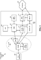
- FIG. 1 is a diagram illustrating an LTE network architecture 100.
- the LTE network architecture 100 may be referred to as an Evolved Packet System (EPS) 100.
- the EPS 100 may include one or more user equipment (UE) 102, an Evolved UMTS Terrestrial Radio Access Network (E-UTRAN) 104, an Evolved Packet Core (EPC) 110, and an Operator's Internet Protocol (IP) Services 122.
- the EPS can interconnect with other access networks, but for simplicity those entities/interfaces are not shown.
- the EPS provides packet-switched services, however, as those skilled in the art will readily appreciate, the various concepts presented throughout this disclosure may be extended to networks providing circuit-switched services.
- the E-UTRAN includes the evolved Node B (eNB) 106 and other eNBs 108, and may include a Multicast Coordination Entity (MCE) 128.
- the eNB 106 provides user and control planes protocol terminations toward the UE 102.
- the eNB 106 may be connected to the other eNBs 108 via a backhaul (e.g., an X2 interface).
- the MCE 128 allocates time/frequency radio resources for evolved Multimedia Broadcast Multicast Service (eMBMS), and determines the radio configuration (e.g., a modulation and coding scheme (MCS)) for the eMBMS.
- MCS modulation and coding scheme
- the MCE 128 may be a separate entity or part of the eNB 106.
- the eNB 106 may also be referred to as a base station, a Node B, an access point, a base transceiver station, a radio base station, a radio transceiver, a transceiver function, a basic service set (BSS), an extended service set (ESS), or some other suitable terminology.
- the eNB 106 provides an access point to the EPC 110 for a UE 102.
- Examples of UEs 102 include a cellular phone, a smart phone, a session initiation protocol (SIP) phone, a laptop, a personal digital assistant (PDA), a satellite radio, a global positioning system, a multimedia device, a video device, a digital audio player (e.g., MP3 player), a camera, a game console, a tablet, or any other similar functioning device.
- SIP session initiation protocol
- PDA personal digital assistant
- satellite radio a global positioning system
- multimedia device e.g., a digital audio player (e.g., MP3 player), a camera, a game console, a tablet, or any other similar functioning device.
- MP3 player digital audio player
- the UE 102 may also be referred to by those skilled in the art as a mobile station, a subscriber station, a mobile unit, a subscriber unit, a wireless unit, a remote unit, a mobile device, a wireless device, a wireless communications device, a remote device, a mobile subscriber station, an access terminal, a mobile terminal, a wireless terminal, a remote terminal, a handset, a user agent, a mobile client, a client, or some other suitable terminology.
- the eNB 106 is connected to the EPC 110.
- the EPC 110 may include a Mobility Management Entity (MME) 112, a Home Subscriber Server (HSS) 120, other MMEs 114, a Serving Gateway (SGW) 116, a Multimedia Broadcast Multicast Service (MBMS) Gateway 124, a Broadcast Multicast Service Center (BM-SC) 126, and a Packet Data Network (PDN) Gateway (PGW) 118.
- MME 112 is the control node that processes the signaling between the UE 102 and the EPC 110. Generally, the MME 112 provides bearer and connection management. All user IP packets are transferred through the Serving Gateway 116, which itself is connected to the PDN Gateway 118.
- the PDN Gateway 118 provides UE IP address allocation as well as other functions.
- the PDN Gateway 118 and the BM-SC 126 are connected to the IP Services 122.
- the IP Services 122 may include the Internet, an intranet, an IP Multimedia Subsystem (IMS), a PS Streaming Service (PSS), and/or other IP services.
- the BM-SC 126 may provide functions for MBMS user service provisioning and delivery.
- the BM-SC 126 may serve as an entry point for content provider MBMS transmission, may be used to authorize and initiate MBMS Bearer Services within a Public Land Mobile Network (PLMN), and may be used to schedule and deliver MBMS transmissions.
- PLMN Public Land Mobile Network
- the MBMS Gateway 124 may be used to distribute MBMS traffic to the eNBs (e.g., 106, 108) belonging to a Multicast Broadcast Single Frequency Network (MBSFN) area broadcasting a particular service, and may be responsible for session management (start/stop) and for collecting eMBMS related charging information.
- MMSFN Multicast Broadcast Single Frequency Network
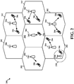
- FIG. 2 is a diagram illustrating an example of an access network 200 in an LTE network architecture.
- the access network 200 is divided into a number of cellular regions (cells) 202.
- One or more lower power class eNBs 208 may have cellular regions 210 that overlap with one or more of the cells 202.
- the lower power class eNB 208 may be a femto cell (e.g., home eNB (HeNB)), pico cell, micro cell, or remote radio head (RRH).
- HeNB home eNB
- RRH remote radio head
- the macro eNBs 204 are each assigned to a respective cell 202 and are configured to provide an access point to the EPC 110 for all the UEs 206 in the cells 202.
- the eNBs 204 are responsible for all radio related functions including radio bearer control, admission control, mobility control, scheduling, security, and connectivity to the serving gateway 116.
- An eNB may support one or multiple (e.g., three) cells (also referred to as a sectors).
- the term "cell” can refer to the smallest coverage area of an eNB and/or an eNB subsystem serving are particular coverage area. Further, the terms “eNB,” “base station,” and “cell” may be used interchangeably herein.
- the modulation and multiple access scheme employed by the access network 200 may vary depending on the particular telecommunications standard being deployed.
- OFDMA is used on the DL
- SC-FDMA is used on the UL to support both frequency division duplex (FDD) and time division duplex (TDD).
- FDD frequency division duplex
- TDD time division duplex
- FDD frequency division duplex
- TDD time division duplex
- EV-DO Evolution-Data Optimized
- UMB Ultra Mobile Broadband
- EV-DO and UMB are air interface standards promulgated by the 3rd Generation Partnership Project 2 (3GPP2) as part of the CDMA2000 family of standards and employs CDMA to provide broadband Internet access to mobile stations. These concepts may also be extended to Universal Terrestrial Radio Access (UTRA) employing Wideband-CDMA (W-CDMA) and other variants of CDMA, such as TD-SCDMA; Global System for Mobile Communications (GSM) employing TDMA; and Evolved UTRA (E-UTRA), IEEE 802.11 (Wi-Fi), IEEE 802.16 (WiMAX), IEEE 802.20, and Flash-OFDM employing OFDMA.
- UTRA, E-UTRA, UMTS, LTE and GSM are described in documents from the 3GPP organization.
- CDMA2000 and UMB are described in documents from the 3GPP2 organization. The actual wireless communication standard and the multiple access technology employed will depend on the specific application and the overall design constraints imposed on the system.
- the eNBs 204 may have multiple antennas supporting MIMO technology.
- MIMO technology enables the eNBs 204 to exploit the spatial domain to support spatial multiplexing, beamforming, and transmit diversity.
- Spatial multiplexing may be used to transmit different streams of data simultaneously on the same frequency.
- the data streams may be transmitted to a single UE 206 to increase the data rate or to multiple UEs 206 to increase the overall system capacity. This is achieved by spatially precoding each data stream (i.e., applying a scaling of an amplitude and a phase) and then transmitting each spatially precoded stream through multiple transmit antennas on the DL.
- the spatially precoded data streams arrive at the UE(s) 206 with different spatial signatures, which enables each of the UE(s) 206 to recover the one or more data streams destined for that UE 206.
- each UE 206 transmits a spatially precoded data stream, which enables the eNB 204 to identify the source of each spatially precoded data stream.
- Beamforming may be used to focus the transmission energy in one or more directions. This may be achieved by spatially precoding the data for transmission through multiple antennas. To achieve good coverage at the edges of the cell, a single stream beamforming transmission may be used in combination with transmit diversity.
- OFDM is a spread-spectrum technique that modulates data over a number of subcarriers within an OFDM symbol.
- the subcarriers are spaced apart at precise frequencies. The spacing provides "orthogonality" that enables a receiver to recover the data from the subcarriers.
- a guard interval e.g., cyclic prefix
- the UL may use SC-FDMA in the form of a DFT-spread OFDM signal to compensate for high peak-to-average power ratio (PAPR).
- PAPR peak-to-average power ratio
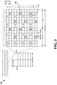
- FIG. 3 is a diagram 300 illustrating an example of a DL frame structure in LTE using normal cyclic prefix.
- a frame (10 ms) may be divided into 10 equally sized subframes each of duration 1 ms. Each subframe may include two consecutive time slots.
- a resource grid may be used to represent two time slots, each time slot including a resource block. The resource grid is divided into multiple resource elements.
- a resource block contains 12 consecutive subcarriers in the frequency domain and 7 consecutive OFDM symbols in the time domain, for a total of 84 resource elements.
- For an extended cyclic prefix a resource block contains 12 consecutive subcarriers in the frequency domain and 6 consecutive OFDM symbols in the time domain, for a total of 72 resource elements.
- Some of the resource elements, indicated as R 302, 304, include DL reference signals (DL-RS).
- the DL-RS include Cell-specific RS (CRS) (also sometimes called common RS) 302 and UE-specific RS (UE-RS) 304.
- UE-RS 304 are transmitted only on the resource blocks upon which the corresponding physical DL shared channel (PDSCH) is mapped.
- PDSCH physical DL shared channel
- the number of bits carried by each resource element depends on the modulation scheme. Thus, the more resource blocks that a UE receives and the higher the modulation scheme, the higher the data rate for the UE.
- FIG. 4 is a diagram 400 illustrating an example of an UL frame structure in LTE.
- the available resource blocks for the UL may be partitioned into a data section and a control section.
- the control section may be formed at the two edges of the system bandwidth and may have a configurable size.
- the resource blocks in the control section may be assigned to UEs for transmission of control information.
- the data section may include all resource blocks not included in the control section.
- the UL frame structure results in the data section including contiguous subcarriers, which may allow a single UE to be assigned all of the contiguous subcarriers in the data section.
- a UE may be assigned resource blocks 410a, 410b in the control section to transmit control information to an eNB.
- the UE may also be assigned resource blocks 420a, 420b in the data section to transmit data to the eNB.
- the UE may transmit control information in a physical UL control channel (PUCCH) on the assigned resource blocks in the control section.
- the UE may transmit only data or both data and control information in a physical UL shared channel (PUSCH) on the assigned resource blocks in the data section.
- a UL transmission may span both slots of a subframe and may hop across frequency.
- a set of resource blocks may be used to perform initial system access and achieve UL synchronization in a physical random access channel (PRACH) 430.
- the PRACH 430 carries a random sequence and cannot carry any UL data/signaling.
- Each random access preamble occupies a bandwidth corresponding to six consecutive resource blocks.
- the starting frequency is specified by the network. That is, the transmission of the random access preamble is restricted to certain time and frequency resources. There is no frequency hopping for the PRACH.
- the PRACH attempt is carried in a single subframe (1 ms) or in a sequence of few contiguous subframes and a UE can make only a single PRACH attempt per frame (10 ms).
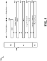
- FIG. 5 is a diagram 500 illustrating an example of a radio protocol architecture for the user and control planes in LTE.
- the radio protocol architecture for the UE and the eNB is shown with three layers: Layer 1, Layer 2, and Layer 3.
- Layer 1 (L1 layer) is the lowest layer and implements various physical layer signal processing functions.
- the L1 layer will be referred to herein as the physical layer 506.
- Layer 2 (L2 layer) 508 is above the physical layer 506 and is responsible for the link between the UE and eNB over the physical layer 506.
- the L2 layer 508 includes a media access control (MAC) sublayer 510, a radio link control (RLC) sublayer 512, and a packet data convergence protocol (PDCP) 514 sublayer, which are terminated at the eNB on the network side.
- MAC media access control
- RLC radio link control
- PDCP packet data convergence protocol
- the UE may have several upper layers above the L2 layer 508 including a network layer (e.g., IP layer) that is terminated at the PDN gateway 118 on the network side, and an application layer that is terminated at the other end of the connection (e.g., far end UE, server, etc.).
- IP layer e.g., IP layer
- the PDCP sublayer 514 provides multiplexing between different radio bearers and logical channels.
- the PDCP sublayer 514 also provides header compression for upper layer data packets to reduce radio transmission overhead, security by ciphering the data packets, and handover support for UEs between eNBs.
- the RLC sublayer 512 provides segmentation and reassembly of upper layer data packets, retransmission of lost data packets, and reordering of data packets to compensate for out-of-order reception due to hybrid automatic repeat request (HARQ).
- HARQ hybrid automatic repeat request
- the MAC sublayer 510 provides multiplexing between logical and transport channels.
- the MAC sublayer 510 is also responsible for allocating the various radio resources (e.g., resource blocks) in one cell among the UEs.
- the MAC sublayer 510 is also responsible for HARQ operations.
- the radio protocol architecture for the UE and eNB is substantially the same for the physical layer 506 and the L2 layer 508 with the exception that there is no header compression function for the control plane.
- the control plane also includes a radio resource control (RRC) sublayer 516 in Layer 3 (L3 layer).
- RRC sublayer 516 is responsible for obtaining radio resources (e.g., radio bearers) and for configuring the lower layers using RRC signaling between the eNB and the UE.
- FIG. 6 is a block diagram of an eNB 610 in communication with a UE 650 in an access network.
- upper layer packets from the core network are provided to a controller/processor 675.
- the controller/processor 675 implements the functionality of the L2 layer.
- the controller/processor 675 provides header compression, ciphering, packet segmentation and reordering, multiplexing between logical and transport channels, and radio resource allocations to the UE 650 based on various priority metrics.
- the controller/processor 675 is also responsible for HARQ operations, retransmission of lost packets, and signaling to the UE 650.
- the transmit (TX) processor 616 implements various signal processing functions for the L1 layer (i.e., physical layer).
- the signal processing functions include coding and interleaving to facilitate forward error correction (FEC) at the UE 650 and mapping to signal constellations based on various modulation schemes (e.g., binary phase-shift keying (BPSK), quadrature phase-shift keying (QPSK), M-phase-shift keying (M-PSK), M-quadrature amplitude modulation (M-QAM)).
- FEC forward error correction
- BPSK binary phase-shift keying
- QPSK quadrature phase-shift keying
- M-PSK M-phase-shift keying
- M-QAM M-quadrature amplitude modulation
- Each stream is then mapped to an OFDM subcarrier, multiplexed with a reference signal (e.g., pilot) in the time and/or frequency domain, and then combined together using an Inverse Fast Fourier Transform (IFFT) to produce a physical channel carrying a time domain OFDM symbol stream.
- the OFDM stream is spatially precoded to produce multiple spatial streams.
- Channel estimates from a channel estimator 674 may be used to determine the coding and modulation scheme, as well as for spatial processing.
- the channel estimate may be derived from a reference signal and/or channel condition feedback transmitted by the UE 650.
- Each spatial stream may then be provided to a different antenna 620 via a separate transmitter 618TX.
- Each transmitter 618TX may modulate an RF carrier with a respective spatial stream for transmission.
- each receiver 654RX receives a signal through its respective antenna 652.
- Each receiver 654RX recovers information modulated onto an RF carrier and provides the information to the receive (RX) processor 656.
- the RX processor 656 implements various signal processing functions of the L1 layer.
- the RX processor 656 may perform spatial processing on the information to recover any spatial streams destined for the UE 650. If multiple spatial streams are destined for the UE 650, they may be combined by the RX processor 656 into a single OFDM symbol stream.
- the RX processor 656 then converts the OFDM symbol stream from the time-domain to the frequency domain using a Fast Fourier Transform (FFT).
- FFT Fast Fourier Transform
- the symbols on each subcarrier, and the reference signal, are recovered and demodulated by determining the most likely signal constellation points transmitted by the eNB 610. These soft decisions may be based on channel estimates computed by the channel estimator 658. The soft decisions are then decoded and deinterleaved to recover the data and control signals that were originally transmitted by the eNB 610 on the physical channel. The data and control signals are then provided to the controller/processor 659.
- the controller/processor 659 implements the L2 layer.
- the controller/processor can be associated with a memory 660 that stores program codes and data.
- the memory 660 may be referred to as a computer-readable medium.
- the controller/processor 659 provides demultiplexing between transport and logical channels, packet reassembly, deciphering, header decompression, control signal processing to recover upper layer packets from the core network.
- the upper layer packets are then provided to a data sink 662, which represents all the protocol layers above the L2 layer.
- Various control signals may also be provided to the data sink 662 for L3 processing.
- the controller/processor 659 is also responsible for error detection using an acknowledgement (ACK) and/or negative acknowledgement (NACK) protocol to support HARQ operations.
- ACK acknowledgement
- NACK negative acknowledgement
- a data source 667 is used to provide upper layer packets to the controller/processor 659.
- the data source 667 represents all protocol layers above the L2 layer.
- the controller/processor 659 implements the L2 layer for the user plane and the control plane by providing header compression, ciphering, packet segmentation and reordering, and multiplexing between logical and transport channels based on radio resource allocations by the eNB 610.
- the controller/processor 659 is also responsible for HARQ operations, retransmission of lost packets, and signaling to the eNB 610.
- Channel estimates derived by a channel estimator 658 from a reference signal or feedback transmitted by the eNB 610 may be used by the TX processor 668 to select the appropriate coding and modulation schemes, and to facilitate spatial processing.
- the spatial streams generated by the TX processor 668 may be provided to different antenna 652 via separate transmitters 654TX. Each transmitter 654TX may modulate an RF carrier with a respective spatial stream for transmission.
- the UL transmission is processed at the eNB 610 in a manner similar to that described in connection with the receiver function at the UE 650.
- Each receiver 618RX receives a signal through its respective antenna 620.
- Each receiver 618RX recovers information modulated onto an RF carrier and provides the information to a RX processor 670.
- the RX processor 670 may implement the L1 layer.
- the controller/processor 675 implements the L2 layer.
- the controller/processor 675 can be associated with a memory 676 that stores program codes and data.
- the memory 676 may be referred to as a computer-readable medium.
- the control/processor 675 provides demultiplexing between transport and logical channels, packet reassembly, deciphering, header decompression, control signal processing to recover upper layer packets from the UE 650.
- Upper layer packets from the controller/processor 675 may be provided to the core network.
- the controller/processor 675 is also responsible for error detection using an ACK and/or NACK protocol to support HARQ operations
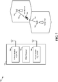
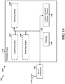
- FIG. 7 is an illustration 700 of a UE 702 with multiple radios.
- the UE 702 may contain a WWAN (2/3/4G LTE) radio 704 and WLAN (802.11) radio 706.
- WWAN radios and WLAN radios are initially designed for specific communication needs, with advances in technology and needs for higher data rates, the use of these two types of radios has started to overlap.
- One such assistance can be during inter-frequency measurements for LTE.
- the WLAN radio 706 may assist in cell search and cell measurement for LTE at other frequencies than the serving cell frequency.
- a UE 702 may need to monitor neighboring cells for potential handovers when the serving cell signal strength becomes weak compared to a predefined threshold.
- the neighbor cell search and measurement is an inter-frequency cell search and measurement.
- the carrier frequency of a "target" inter-frequency neighbor cell 710 is referred to as "target frequency.”
- target frequency When the target frequency is sufficiently apart from the serving cell frequency, the measurements on target frequency will require the UE 702 to tune away from its serving frequency. Note that the target frequency may belong to the same frequency band as the serving frequency, or it may belong to a different frequency band.
- the WLAN radio may be used to measure one or more target cells 710 on one or more target frequencies, while the WWAN modem measures serving cells 708 on the serving frequency.
- a "serving cell” 708 is a cell with which the WWAN modem 704 is currently connected to, i.e. has a radio connection.
- the serving cell 708 has a base station that communicates with the WWAN modem 704 of the UE 702 over a serving frequency
- An inter-frequency cell referred to as the "target cell” 710 is the cell where the WWAN modem 704 needs to tune away to do inter-frequency measurements on frequencies different from the serving frequency.
- the LTE modem 704 may tune away during specified times referred to as measurement gaps.
- the inter-frequency measurement gaps are configured by the serving eNB allowing the UE to tune away from serving frequency for inter-frequency cell search and measurements.
- the UE is not scheduled any DL packets during these measurement gaps and thus is not receiving any data from the serving cell 708. Similarly the UE cannot transmit UL packets during these measurement gaps to the serving cell 708. This results in loss of DL and UL throughput as opposed to the case where the UE is not scheduled any measurement gaps.
- the use of the WLAN modem 706 to assist inter-frequency measurements avoids measurement gaps, results in higher throughput and better user experience.
- the WLAN modem 706 may be in idle mode while the WWAN modem 704 is in connected mode. Thus, the WLAN modem 706 is available for assisting inter-frequency WWAN measurements. Even when the WLAN modem 706 is in connected mode, the WLAN modem 706 can create gaps in WLAN Tx/Rx for the WWAN inter-frequency measurements if needed.
- Cell search including in particular inter-frequency neighbor cell search, in LTE involves the detection of primary synchronization signals (PSS) and secondary synchronization signals (SSS).
- PSS primary synchronization signals
- SSS secondary synchronization signals
- cell search implementation relies on 6 ms measurement gap length to capture approximately 5.1 ms samples for PSS/SSS detection. The extra .9 ms is needed in order for the modem to tune away to a next frequency, and then to tune back to the original frequency, after capturing signals.
- the 6 ms gaps may occur every 40 ms or 80 ms depending on the measurement gap pattern.
- Such detection requires a modem that is able to collect signal samples at once across a 5.1 ms duration of a radio frame.
- a WWAN modem is able to collect the required number of consecutive samples at once.
- a WLAN modem may not be able to collect all of those samples at once. For example, due to buffer limitations and the need for explicit triggering, a WLAN modem cannot collect samples of 5.1 ms in one shot.
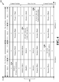
- a WLAN modem may have to do multiple captures in order to collect signal samples for cell search. For example, for a WLAN modem configuration at 57.6 MHz analog-to-digital (ADC) sampling rate, with a 8K sample buffer and 7.56 ⁇ s hardware and software triggering delay causing a gap between captures, requires thirty-five captures with thirty-four gaps between these captures in order to capture the 5.1 ms. Thus, with a WLAN modem there are many instances of captured data followed by a gap. To date, no techniques are available to recover the lost data in those gaps. Therefore, there is a loss in performance together with misdetections and false alarms.
- ADC analog-to-digital
- ADC Sampling MHz
- Capture Duration ⁇ s
- the first communications network may be an LTE network and the signal of interest may be PSS and SSS signals for cell search.
- the second RAT may support a WLAN, such as Wi-Fi, in which case a WLAN modem is used to capture the signals of interest.
- the WLAN modem hardware may also be used to support other communication technologies, such a Bluetooth. In such cases, measures should be taken to ensure that use of the WLAN modem for LTE measurements does not interfere with either of the WLAN communications or the Bluetooth communications.
- Signals of interest are typically transmitted periodically by a communications network.
- PSS signals are periodically transmitted with a period of 5 ms.
- SSS signals have two 5 ms phases and therefore are periodically transmitted with a period of 10 ms.
- captures for durations less than a subframe are periodically repeated over a number of radio frames until a total capture length of 5 ms is obtained.
- the captures are then combined, for example by concatenation, to form 5 ms of continuous data. This way it is guaranteed to have a 5 ms capture with a full PSS and SSS in it.
- FIG. 8 is an illustration 800 of a radio communication frame structure of LTE in the time domain.
- Each radio frame 802 is 10 ms long and includes ten subframes 804.
- Particular signals of interest e.g., PSS 806 and SSS 808, 810, are transmitted in every radio frame 802 and occur at the same place and at the same time.
- PSSs occur at a point in time in subframe 0 and again at the same point in time 5 ms later in subframe 5.
- the PSS occurs at the same times in the next radio frame.
- the first phase of a SSS occurs at a point in time in subframe 0, while the second phase of SSS occurs 5 ms later in subframe 5.
- the first phase of SSS and second phase of SSS occur at the same respective times in the next radio frame.
- an amount of signal samples (also referred to as "data") are captured during a first capture instance beginning at a time t 0 and continuing for a capture length T C .
- the capture length is substantially less than a half frame, e.g., 5 ms, and less than a subframe, e.g., 1 ms.
- the capture length T C is a function of sampling rate and may range from 139 microseconds ( ⁇ s) to 1600 ⁇ s.
- the time t 0 is an arbitrary time at which capture starts.
- samples corresponding to the PSS and SSS are captured. This however, is not necessarily the case, as the data captured depends on the location of the start time t 0 , relative to the position of the signals within the communication frame 802
- the foregoing capturing is repeated for additional communication frames 802 to obtain additional capture instances.
- the additional captures occur at times offset from the capture time of the initial communication frame.
- the offset time may be based on the length of the communication frame and the capture length T C .
- the offset time is equal to the capture length T C plus the length of the communication frame, which is 10 ms. Accordingly, at this offset time an amount of signal samples are captured for a second capture period that also has a capture length T C . As shown in FIG. 8 , during this capture duration, data other than PSS and SSS are captured.
- the process of capturing data for a period of time T C is repeated until a total of 5.1 ms of data is captured.
- the samples captured during these capture instances are concatenated together to form a 5.1 ms continuous data. Because 5.1 ms of continuous data is captured, these data are guaranteed to have a complete PSS and SSS (either Phase 1 or Phase 2) regardless of the starting time t 0 . Therefore they can be treated as if they are received in one shot.
- the data may be provided to a processor, e.g., correlator, to determine the locations of the PSS and SSS within the data.
- the PSS and SSS are then used for cell search and measurement.
- a processor e.g., correlator
- the PSS and SSS are then used for cell search and measurement.
- the drawback is the latency due to the 10 ms periodicity.
- This technique may be more suited for the cases with high performance is necessary and gaps cannot be tolerated within the captured signal.
- another suitable case is where WLAN modem cannot spare 5 ms chunks of its resources at once because it might be serving WLAN application but it can give smaller chunks of time periodically to do LTE tasks.
- a WLAN modem may be available for LTE measurements for a duration larger than the capture lengths described above with reference to FIG. 8 , which were less than one subframe.
- WLAN modems that function to serve both a WLAN e.g., Wi-Fi, and Bluetooth communications
- a capture duration of up to approximately 1.5 ms may be available, while in another Bluetooth communication frame structure, a capture duration of up to approximately 2.8 ms may be available.
- Techniques using such WLAN modems for LTE measurements should not impact LTE performance, nor should they interfere with Bluetooth traffic. This is particularly relevant to modems wherein the WLAN and Bluetooth do not have independent frequency synthesizers.
- FIG. 9 is an illustration 900 of Bluetooth communication windows 902 of a first type along with LTE communication frames 904, both as a function of time.
- the Bluetooth communication windows illustrated are a configuration that facilitates communications in accordance with the enhanced synchronous connection-oriented (eSCO) protocol for voice data.
- the Bluetooth communication windows may be referred to as eSCO windows.
- Each eSCO window 902 includes six Bluetooth slots 906.
- the duration of each slot is 625 ⁇ s.
- the first slot is for master to slave transmissions, while the second slot is slave to master transmissions.
- the first slot and the second slot form an eSCO instant.
- the four slots after the second slot are reserved for retransmissions of packets that did not go through. These four slots form ReTx windows.
- several samples of data transmitted in accordance with a first RAT are captured by a receive chain of a second RAT during portions of several eSCO windows.
- the portion during which capture occurs may be referred to as a capture length T C .
- the data captured during each a capture length T C are combined to form a duration of continuous data in order to obtain a signal of interest.
- the second receive chain foregoes Bluetooth retransmission and instead tunes away to a LTE frequency and captures LTE data.
- the ReTx window may be considered a measurement gap.
- the duration of the ReTx window is approximately 2.5 ms.
- the effective duration of the capture instance 912 i.e., data sample, or a capture length T C , is approximately 1.5 ms.
- the foregoing capturing is repeated for one or more additional eSCO windows 914 and corresponding ReTx windows 916 to obtain additional capture instances. While the additional captures occur at the approximately the same time and for the same duration within each ReTx window, with respect to the LTE communications frame 904, the captures occur at times offset from the capture time of the initial LTE communication frame. For example, in FIG. 9 , the second sample capture begins at time T3, which is approximately 12 ms after the beginning of the first sample capture at time T1. At offset time T3 an amount of signal samples are capture for a second capture period that also has a capture length T C . The process of capturing data for a period of time T C is repeated until a total of 5.1 ms of data is captured.
- FIG. 10 is an illustration 1000 of Bluetooth communication windows 1002 sufficient to capture 5.1 ms of data samples.
- Each communication windows 1002 is designed as either a gap window or a no gap window.
- Gap windows correspond to eSCO windows during which LTE data samples were captured during the ReTx window of the eSCO window.
- No gap windows correspond to eSCO windows during which no LTE data samples were captured during the ReTx window of the eSCO window.
- Bluetooth slots which is approximately 37.5 ms, to capture a number, e.g., four, of LTE data samples sufficient to form an approximately 5.1 ms sample of continuous LTE data. It is also noted that the time between the end of a sample capture and the start of a next sample capture is sixteen Bluetooth slots, which is approximately the duration of a 10 ms LTE radio communication frame.
- the samples captured during these capture instances are concatenated together to form a 5.1 ms continuous data. Because 5.1 ms of continuous data is captured, these data are guaranteed to have a complete PSS and SSS (either Phase 1 or Phase 2).
- the data may be provided to a processor, e.g., correlator, to determine the locations of the PSS and SSS within the data.
- the PSS and SSS are then used for cell search and measurement. In accordance with the foregoing technique, there are no gaps present in the 5.1 ms continuous data.
- FIG. 11 is an illustration 1100 of Bluetooth communication windows 1102 of a second type along with LTE communication frames 1104, both as a function of time.
- the Bluetooth communication windows illustrated facilitate communications in accordance with the enhanced synchronous connection-oriented (eSCO) protocol for voice data.
- eSCO enhanced synchronous connection-oriented
- the Bluetooth communication windows may be referred to as eSCO windows.
- each eSCO window 1102 includes twelve Bluetooth slots 1106.
- the duration of each slot is 625 ⁇ s.
- the first slot is for master to slave transmissions, while the second slot is slave to master transmissions.
- the first slot and the second slot form an eSCO instant.
- the four slots after the second slot are reserved for retransmissions of packets that did not go through. These four slots form ReTx windows.
- the following six slots may be available for LTE measurements and are referred to herein as a measurement window.
- several samples of data transmitted in accordance with a first RAT are captured by a receive chain of a second RAT during portions of several eSCO windows.
- the portion during which capture occurs may be referred to as a capture length T C .
- the data captured during each a capture length T C are combined to form a duration of continuous data in order to obtain a signal of interest.
- the second receive chain tunes away to a LTE frequency and captures LTE data.
- the duration of the ReTx window is approximately 3.75 ms.
- the effective duration of the capture instance 1112 i.e., data sample, or a capture length T C , is approximately 2.8 ms. This is approximately twice as large as the capture length of 1.5 ms available using the first configuration of Bluetooth communication windows shown in FIG. 9 .
- the foregoing capturing is repeated for one additional eSCO windows 1114 and corresponding measurement windows 1116 to obtain additional capture instances. While the additional captures occur at approximately the same time and for the same duration within each measurement window, with respect to the LTE communications frame 1104, the captures occur at times offset from the capture time of the initial LTE communication frame. For example, in FIG. 11 , the second sample capture begins at time T3, which is approximately 7.5 ms after the beginning of the first sample capture at time T1. At offset time T3 an amount of signal samples are capture for a second capture period that also has a capture length T C .
- the two samples captured during these capture instances are concatenated together to form a 5.1 ms continuous data.
- This pattern of capture may be repeated every five eSCO windows. Because 5.1 ms of continuous data is captured, these data are guaranteed to have a complete PSS and SSS (either Phase 1 or Phase 2).
- the data may be provided to a processor, e.g., correlator, to determine the locations of the PSS and SSS within the data.
- the PSS and SSS are then used for cell search and measurement. In accordance with the foregoing technique, there are no gaps present in the 5.1 ms continuous data.
- FIG. 12 is a flow chart 1200 of a method of capturing a signal of interest transmitted by a WWAN during each of a plurality of communication frames.
- the method may be performed by a UE.
- the UE captures data transmitted by the WWAN for a capture length corresponding to a duration less than a periodicity of transmission of the signal of interest.
- Each capture occurs at a different point within its respective communication frame relative to other communication frames, and the capturing is done with a WLAN receive chain.
- the UE captures data for each of a plurality of the communication frames.
- each data capture may begin at a respective capture time.
- the time between consecutive capture times defines a capture period, and the capture period varies among the plurality of data captures.
- the capture period increases for each data capture.
- the periodicity of transmission of the signal of interest is a half frame and the capture length is less than one subframe.
- An example of this implementation is shown in FIG. 8 , where capture length T c is less than one subframe.
- the period of transmission of the signal of interest is a half frame and the capture length is between one subframe and three subframes. Examples of such implementations are shown in FIG. 9 , where the capture length, e.g., sample 912, is approximately 1.5 ms, and in FIG. 11 , where the capture length, e.g., sample 1112, is approximately 2.8 ms.
- the WLAN receive chain may be included in a modem that supports communication by a wireless technology standard that invokes repeating communication windows at least partially overlapping in time with the communication frames.
- the communication windows have corresponding measurement gaps.
- the UE captures data during a respective measurement gap.
- the wireless technology standard may be Bluetooth, in which case the measurement gap corresponds to a number of Bluetooth slots, each slot being approximately 625 ⁇ S long.
- the measurement gap corresponds to four Bluetooth slots, while in FIG. 11 , the measurement gap corresponds to six Bluetooth slots.
- the UE processes the plurality of data captures to form an equivalent continuous data corresponding to a duration greater than the periodicity of transmission of the signal of interest.
- the plurality of data captures may be processed by concatenating the data captures to form the continuous data.
- the UE detects the signal of interest in the continuous data.
- the signal of interest may be at least one of a PSS, a phase 1 SSS, and a phase 2 SSS.
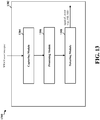
- FIG. 13 is a conceptual data flow diagram 1300 illustrating the data flow between different modules/means/components in an exemplary apparatus 1302.
- the apparatus 1302 may be a UE.
- the apparatus 1302 includes a capturing module 1304, a processing module 1306, and a detecting module 1308.
- the capturing module 1304 captures data transmitted by the WWAN for each of a plurality of the communication frames.
- the data is captured for a capture length corresponding to a duration less than a periodicity of transmission of the signal of interest.
- Each capture occurs at a different point within its respective communication frame relative to other communication frames, and the capturing is done with a WLAN receive chain
- the processing module 1306 processes the plurality of data captures to form an equivalent continuous data corresponding to a duration greater than the periodicity of transmission.
- the detecting module 1308 detects the signal of interest in the continuous data.
- the apparatus may include additional modules that perform each of the steps of the algorithm in the aforementioned flow chart of FIG. 12 .
- each step in the aforementioned flow chart of FIG. 12 may be performed by a module and the apparatus may include one or more of those modules.
- the modules may be one or more hardware components specifically configured to carry out the stated processes/algorithm, implemented by a processor configured to perform the stated processes/algorithm, stored within a computer-readable medium for implementation by a processor, or some combination thereof.
- FIG. 14 is a diagram 1400 illustrating an example of a hardware implementation for an apparatus 1402' employing a processing system 1414.
- the processing system 1414 may be implemented with a bus architecture, represented generally by the bus 1424.
- the bus 1424 may include any number of interconnecting buses and bridges depending on the specific application of the processing system 1414 and the overall design constraints.
- the bus 1424 links together various circuits including one or more processors and/or hardware modules, represented by the processor 1404, the modules 1304, 1306, 1308, and the computer-readable medium / memory 1406.
- the bus 1424 may also link various other circuits such as timing sources, peripherals, voltage regulators, and power management circuits, which are well known in the art, and therefore, will not be described any further.
- the processing system 1414 may be coupled to a WLAN transceiver 1410.
- the WLAN transceiver 1410 is coupled to one or more antennas 1420.
- the WLAN transceiver 1410 provides a means for communicating with various other apparatus over a transmission medium.
- the transceiver 1410 receives a signal, e.g., a WWAN signal, from the one or more antennas 1420, extracts information from the received signal, and provides the extracted information to the processing system 1414.
- the WLAN transceiver 1410 receives information from the processing system 1414, and based on the received information, generates a signal to be applied to the one or more antennas 1420.
- the processing system 1414 includes a processor 1404 coupled to a computer-readable medium / memory 1406.
- the processor 1404 is responsible for general processing, including the execution of software stored on the computer-readable medium / memory 1406.
- the software when executed by the processor 1404, causes the processing system 1414 to perform the various functions described supra for any particular apparatus.
- the computer-readable medium / memory 1406 may also be used for storing data that is manipulated by the processor 1404 when executing software.
- the processing system further includes at least one of the modules 1304, 1306, and 1308.
- the modules may be software modules running in the processor 1404, resident/stored in the computer readable medium / memory 1406, one or more hardware modules coupled to the processor 1404, or some combination thereof.
- the processing system 1414 may be a component of the UE 650 and may include the memory 660 and/or at least one of the TX processor 668, the RX processor 656, and the controller/processor 659.
- the apparatus 1302/1302' for wireless communication includes means for capturing data transmitted by the WWAN for each of a plurality of the communication frames, wherein the data is captured for a capture length corresponding to a duration less than a periodicity of transmission of the signal of interest, and each capture occurs at a different point within its respective communication frame relative to other communication frames, and the capturing is done with a WLAN receive chain.
- the apparatus 1302/1302' also includes means for processing the plurality of data captures to form an equivalent continuous data corresponding to a duration greater than the periodicity of transmission, and means for detecting the signal of interest in the continuous data.
- the aforementioned means may be one or more of the aforementioned modules of the apparatus 1302 and/or the processing system 1314 of the apparatus 1302' configured to perform the functions recited by the aforementioned means.
- the processing system 1314 may include the TX Processor 668, the RX Processor 656, and the controller/processor 659.
- the aforementioned means may be the TX Processor 668, the RX Processor 656, and the controller/processor 659 configured to perform the functions recited by the aforementioned means.
- the techniques described above apply to situations where the availability of the WLAN radio does not allow for a capture duration sufficient to capture a signal of interest in a single shot.
- the situations above do not allow for a WLAN modem to capture 5.1 ms of data at once. Accordingly, multiple captures occur over time and are accumulated to obtain the 5.1 ms of data.
- the WLAN modem may be available for longer periods of time to allow for signal capture in a single shot.
- use of the LTE inter-frequency cell search and measurement assistance interrupts WLAN operation. Accordingly, even through the WLAN radio may be available for a longer period of time, care must be taken so as not to detrimentally impact WLAN performance.
- LTE measurements by WLAN receive chain for WLAN only traffic and WLAN+BT traffic may detrimentally impact WLAN operation, thereby leading to poor mobility performance, and diminished WLAN or WLAN+ Bluetooth quality of service.
- Bluetooth only traffic may not be a problem when WLAN and Bluetooth have independent frequency synthesizers
- the techniques for coexistence of LTE measurements using WLAN receive chain with WLAN and Bluetooth traffic disclosed herein meet LTE measurement periodicity, accuracy and other standards requirements; result in no or minimal degradation to WLAN or WLAN + Bluetooth quality of service, and allow for realization of the full benefits of LTE measurements by a WLAN receive chain, including avoidance of throughput loss due to measurement gaps, and expedited inter-frequency cell detection and offload.
- the techniques also avoid the need for dynamic change of UE capability with respect to the need for measurement gaps. In other words, implementation of the techniques provide for WLAN modem availability for LTE measurements, regardless of UE capability.
- a process for coexistence of LTE measurement using a WLAN radio for capturing a signal of interest periodically transmitted by a WWAN includes periodically obtaining access to a WLAN receive chain for a period of time corresponding to a measurement gap. Access may be obtained in competition with actual WLAN traffic. Once access to the WLAN receive chain is obtained, the signal of interest is captured during the measurement gap over using the WLAN receive chain. The signal may be captured in a single shot. In other words, the duration of capture during the measurement gap may be sufficiently long so as to capture the single of interest.
- the process may further include periodically repeating the obtaining and the capturing.
- LTE data is captured by a WLAN modem during a capture length which is based on a measurement gap duration of a communication frame.
- the capturing is repeated for one or more additional communication frames based on a measurement gap repetition period.
- the measurement gap repetition period defines the spacing between consecutive measurement gaps. Measurements made using the WLAN modem may be scheduled so as to adjust one or more of the measurement gap duration or the measurement gap repetition period during one or more of the additional captures using several options.
- LTE measurements may be made based on the LTE measurement gap pattern id# 0. In this pattern, measurements are made during a 6 ms measurement gap duration, every 40 ms (the measurement gap repetition period). In this case channel unavailability for WLAN + Bluetooth would be about 15%.
- a more aggressive gap pattern may be used, provided there is no interference with Wi-Fi and Bluetooth.
- measurements by the WLAN modem may be made for 6 ms plus an additional time, every 40 ms, or for 6 ms every 20 ms.
- the additional time may be between .1 and .5 ms.
- the channel unavailability for WLAN + Bluetooth is greater than 15%.
- the measurement gap length may be fixed at 6 ms and measurement gap repetition period is adaptive.
- the repetition period may reduce every measurement gap such that a first 6 ms measurement gap occurs over the first 40 ms, a second 6 ms measurement gap occurs over the next 30 ms, a third 6 ms measurement gap occurs over the next 50 ms, and a fourth 6 ms measurement gap occurs over the next 40 ms.
- the following requirements must be met.
- a minimum available time for inter-frequency measurements during 480 ms period is 60 ms. Other requirements for cell detection, measurement accuracy, etc. also apply.
- access to a WLAN receive chain for purposes related to LTE measurements may be obtained using WLAN protocol or operating features. These protocols or features may lead an access point to grant WLAN receive chain access for LTE measurements over competing WLAN traffic.
- a requirement to make LTE measurements with the WLAN radio is treated as a virtual WLAN flow/queue. It is a virtual queue because the WLAN modem does not have packets to transmit while it is being used for LTE cell search and measurement. Flow characteristics are assigned to the virtual flow so it will compete with actual WLAN flows. Based on the relative priorities of the flows, either the virtual flow will obtain access to the WLAN receive chain for LTE measurements, or an actual flow will obtain access to the WLAN receive chain for its purposes, e.g., voice, video.
- This mechanism may be used even when there are real time traffic flows over WLAN in the station, e.g. UE.
- the particular station may be using voice over Wi-Fi or video streaming, with the virtual flow assigned for the LTE measurements, and assignment of appropriate parameters, it is ensured that the virtual flow is not blocking other stations from using the WLAN receive chain.
- LTE measurements obtained by a WLAN receive chain may be treated as a virtual flow/queue with its own Arbitration Inter Frame Space (AIFS) and contention window (CW) maximum and CW minimum, i.e., CWmin, CWmax, for its access category (AC).
- AIFS Arbitration Inter Frame Space
- CW contention window
- AC access category
- different types of WLAN traffic e.g., voice, radio, etc.
- the access category determines the priority of access and length of access based on the assigned AIFS, contention window and TXOP.
- Example access categories include:
- a transmit opportunity is a bounded time interval during which a station can send as many frames as possible (as long as the duration of the transmissions does not extend beyond the maximum duration of the TXOP).
- CWmin, CWmax indicate how long the WLAN modem should backoff when it senses that the WLAN receive chain associated with the AC is busy. Lower priority traffic will wait for a longer time than higher priority traffic.
- TXOP is approximately 1.5 ms for Voice and approximately 3 ms for Video.
- the TXOP for the virtual flow is set to 6 ms in order to obtain a duration sufficient to capture 5.1 ms for LTE measurements. Intra-station other queues will treat this as if LTE measurement "virtual flow" flow is using TXOP of 6 ms though no frames are transmitted over the air.
- a station has one queue that wants to send data.
- a LTE measurement "virtual flow" wants to use the WLAN receive chain to perform LTE measurements.
- the queue for which AIFS and backoff period counts down to zero first wins the contention.
- Lower priority queue doubles the contention window and calculates a new backoff period as if a "physical collision” happened. If both queues count down to zero at the same time, a virtual collision occurs and the higher priority queue gets to transmit, while the lower priority queue follows the same procedure as if a "physical" collision had happened.
- a WLAN modem captures WWAN signals, e.g., LTE signals, while the station is in a power save mode.
- WWAN signals e.g., LTE signals
- a station seeking to perform LTE measurements sets its WLAN radio to a power save mode after a period of WLAN inactivity. While the station is in power save mode, the access point thinks that the station powered off its transceiver to save power. However, in reality the WLAN modem is performing LTE measurements. After a period of inactivity, the station wakes up to see if its access point has any frames buffered for it. The periodicity of wake up by the WLAN radio is agreed upon between the access point and the WLAN radio. If the station has uplink traffic it will come out of the power save mode. The station may also come out of the power save mode if there is any downlink data buffered for it at the access point. In this case, the access point wakes up the station.
- U-APSD Unscheduled Automatic Power Save Delivery
- WMM-PS WMM Power Save
- WMM-PS Power Save Multi-Poll
- PSMP Power Save Multi-Poll
- existing 802.11k framework is leveraged to obtain access to WLAN receive chain for purposes of performing LTE measurements.
- This framework allows a station to autonomously decide to go from a Wi-Fi channel to a non-operating Wi-Fi channel for making LTE measurements for a specified duration determined by the station itself. For example, if a station is communicating with an access point on Wi-Fi channel 1, the station can to go to Wi-Fi channel 2 to make LTE measurements. Alternatively, the station may be asked by the access point or some other station to go to Wi-Fi channel 2. Once at the second Wi-Fi channel the station tunes away to the LTE frequency to make LTE measurements. In this proposal, the measuring station interrupts its data communication with the access point on the operating channel.
- the LTE measurement duration on the non-operating channel may be based on the beacon interval.
- a typical bean interval is approximately 100 ms, which exceeds the approximately 72 ms needed to perform LTE measurements.
- the station determines the interval time between successive non-operating channel measurements.
- the interval time may be a fixed length, e.g., every 480 ms, or it may be determined by the station using application-specific knowledge.
- the measurement duration on non operating channel is defined by dot11RRMNonOperating-ChannelMaxMeasurementDuration.
- the duration is sufficient to capture multiple 5.1 ms worth of samples, while the other stations are not blocked from using the WLAN receive chain.
- this proposal may not be suitable for real-time traffic.
- the network allocation vector (NAV) is set to provide access to the WLAN receive chain for LTE measurements.
- the duration field in 802.11 is 16 bits. Therefore the largest value it could reserve the media for is 65,535 microseconds. However the standard explicitly states to ignore any values greater than 32,767. Accordingly, no certified station would grab the WLAN receive chain for this long. However, some stations may indicate a duration comparable to 6 ms.
- Access to a WLAN receive chain is granted based on the NAV setting.
- LTE measurements will be scheduled. If the NAV ⁇ 6 ms, 6 ms LTE measurements may be scheduled if the priority of LTE measurements "virtual" queue is highest amongst all queues. This process sets NAV to 6 ms so the virtual carrier sensing mechanism will not detect the WLAN receive chain as idle until LTE measurements are completed.
- a station In another process of obtaining access to a WLAN receive chain for a period of time corresponding to a measurement gap, in Soft-AP mode, a station functions both a client and an access point. In this case, the station may use the WWAN as backhaul for providing internet connection to other devices. This may be leveraged for LTE measurements where the station mode is not available during LTE measurements. Client switches between station and LTE measurement mode similar to the soft-AP mode where client switches between station and access point modes.
- WLAN In the case of a 2x2 antenna configuration, if WLAN is using only one antenna, then LTE measurements can use the other antenna. There is no impact to WLAN. If WLAN is using two antennas, then one antenna is unavailable for ⁇ 15% of the time. During handshaking between WLAN and WWAN modems, if WLAN indicates capability for LTE measurements, LTE measurements will have a guaranteed quality of service. Otherwise, if LTE measurement requirements cannot be met, WLAN informs WWAN modem about this and the UE sends updated EUTRA capability to eNB regarding need for gaps for inter-frequency measurements. Handshaking done when new RRC connection is being established
- WLAN and Bluetooth have separate receive chains and independent frequency synthesizers, although a local oscillator is shared.
- the WLAN Tx/Rx is on the 5G band and the Bluetooth Tx/Rx is on the 2.4G band, both can operate independently, even for 1x1 antenna configuration.
- LTE measurements are obtained using the WLAN receive chain, and LTE measurements are on non ISM band, LTE measurements can occur simultaneously with Bluetooth operation, without affecting Bluetooth, due to frequency separation and independent synthesizers.
- Coexistence between WLAN and Bluetooth may be more challenging as residual channel availability after WLAN and Bluetooth usage may not be sufficient for measurements. Coexistence will need updated arbitration procedures. For example, for non-measurement mode, existing arbitration procedures for WLAN and Bluetooth apply; for measurement mode, no WLAN Tx/Rx; Bluetooth Tx/Rx can happen independently. Maximal overlap between Bluetooth and LTE measurements is desired as they can happen without impacting each other while WLAN will be impacted by both LTE measurements and Bluetooth, for 1x1 antenna configuration.
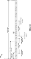
- FIG. 15 is a flow chart 1500 of a method of capturing a signal of interest periodically transmitted by a WWAN.
- the method may be performed by a UE.
- the UE obtains access to a WLAN receive chain for a period of time corresponding to a measurement gap.
- the UE captures the signal of interest during the measurement gap using the WLAN receive chain.
- the UE optionally adjusts one or more of the capture periodicity and the measurement gap. The method then returns to step 1502, where the obtaining - and subsequently the capturing are repeated.
- the UE detects the signal of interest in the data captured during the one or more measurement gaps.
- Access to a WLAN receive chain may be obtained in any one of several ways described above. For example, access may be obtained by 1) requesting WLAN receive chain access for LTE measurements through a virtual flow, 2) entering into a power save mode, 3) tuning to a non-operating WLAN channel, 4) setting network allocation vector (NAV) at or above a threshold value, or 5) entering a measurement mode during which the WLAN receive chain is prevented from performing WLAN operations.
- NAV network allocation vector
- FIG. 16 is a conceptual data flow diagram 1600 illustrating the data flow between different modules/means/components in an exemplary apparatus 1602.
- the apparatus 1602 may be a UE.
- the apparatus 1602 includes an access module 1604, a capture module 1606, an optional adjustment module 1608, and a detecting module 1610.
- the access module 1604 obtains access to a WLAN receive chain for a period of time corresponding to a measurement gap.
- the capture module 1606 captures the signal of interest during the measurement gap using the WLAN receive chain.
- the adjustment module 1608 adjusts one or more of the capture periodicity and the measurement gap prior to the access module 1604 obtaining access to a WLAN receive chain again, and the capture module capturing the signal of interest again.
- the detecting module 1610 detects the signal of interest in the data captured by the capturing module 1606 during the one or more measurement gaps.
- the apparatus may include additional modules that perform each of the steps of the algorithm in the aforementioned flow chart of FIG. 15 .
- each step in the aforementioned flow charts of FIG. 15 may be performed by a module and the apparatus may include one or more of those modules.
- the modules may be one or more hardware components specifically configured to carry out the stated processes/algorithm, implemented by a processor configured to perform the stated processes/algorithm, stored within a computer-readable medium for implementation by a processor, or some combination thereof.
- FIG. 17 is a diagram 1700 illustrating an example of a hardware implementation for an apparatus 1602' employing a processing system 1714.
- the processing system 1714 may be implemented with a bus architecture, represented generally by the bus 1724.
- the bus 1724 may include any number of interconnecting buses and bridges depending on the specific application of the processing system 1714 and the overall design constraints.
- the bus 1724 links together various circuits including one or more processors and/or hardware modules, represented by the processor 1704, the modules 1604, 1606, 1608, 1610 and the computer-readable medium / memory 1706.
- the bus 1724 may also link various other circuits such as timing sources, peripherals, voltage regulators, and power management circuits, which are well known in the art, and therefore, will not be described any further.
- the processing system 1714 may be coupled to a WLAN transceiver 1710.
- the WLAN transceiver 1710 is coupled to one or more antennas 1720.
- the WLAN transceiver 1710 provides a means for communicating with various other apparatus over a transmission medium.
- the WLAN transceiver 1710 receives a signal from the one or more antennas 1720, extracts information from the received signal, and provides the extracted information to the processing system 1714.
- the WLAN transceiver 1710 receives information from the processing system 1714, and based on the received information, generates a signal to be applied to the one or more antennas 1720.
- the processing system 1714 includes a processor 1704 coupled to a computer-readable medium / memory 1706.
- the processor 1704 is responsible for general processing, including the execution of software stored on the computer-readable medium / memory 1706.
- the software when executed by the processor 1704, causes the processing system 1714 to perform the various functions described supra for any particular apparatus.
- the computer-readable medium / memory 1706 may also be used for storing data that is manipulated by the processor 1704 when executing software.
- the processing system further includes at least one of the modules 1604, 1606, 1608 and 1610.
- the modules may be software modules running in the processor 1704, resident/stored in the computer readable medium / memory 1706, one or more hardware modules coupled to the processor 1604, or some combination thereof.
- the processing system 1714 may be a component of the UE 650 and may include the memory 660 and/or at least one of the TX processor 668, the RX processor 656, and the controller/processor 659.
- the apparatus 1602/1602' for wireless communication includes means for obtaining access to a WLAN receive chain for a period of time corresponding to a measurement gap, means for capturing the signal of interest during the measurement gap using the WLAN receive chain, means for periodically repeating the obtaining and the capturing, and means for detecting the signal of interest in the data captured during one or more measurement gaps.
- the apparatus 1602/1602' may also include means for adjusting one or more of the capture periodicity and the measurement gap during the repeating.
- the aforementioned means may be one or more of the aforementioned modules of the apparatus 1602 and/or the processing system 1714 of the apparatus 1602' configured to perform the functions recited by the aforementioned means.
- the processing system 1714 may include the TX Processor 668, the RX Processor 656, and the controller/processor 659.
- the aforementioned means may be the TX Processor 668, the RX Processor 656, and the controller/processor 659 configured to perform the functions recited by the aforementioned means.
- Combinations such as "at least one of A, B, or C,” “at least one of A, B, and C,” and “A, B, C, or any combination thereof' include any combination of A, B, and/or C, and may include multiples of A, multiples of B, or multiples of C.
- combinations such as “at least one of A, B, or C,” “at least one of A, B, and C,” and “A, B, C, or any combination thereof' may be A only, B only, C only, A and B, A and C, B and C, or A and B and C, where any such combinations may contain one or more member or members of A, B, or C.
- nothing disclosed herein is intended to be dedicated to the public regardless of whether such disclosure is explicitly recited in the claims. No claim element is to be construed as a means plus function unless the element is expressly recited using the phrase "means for.”
Landscapes
- Engineering & Computer Science (AREA)
- Computer Networks & Wireless Communication (AREA)
- Signal Processing (AREA)
- Mobile Radio Communication Systems (AREA)
Applications Claiming Priority (2)
| Application Number | Priority Date | Filing Date | Title |
|---|---|---|---|
| US14/252,773 US9686705B2 (en) | 2014-04-14 | 2014-04-14 | Capture of PSS and SSS with wireless local area network receive chain |
| PCT/US2015/025354 WO2015160658A1 (en) | 2014-04-14 | 2015-04-10 | Capture of pss and sss with wireless local area network receive chain |
Publications (2)
| Publication Number | Publication Date |
|---|---|
| EP3132649A1 EP3132649A1 (en) | 2017-02-22 |
| EP3132649B1 true EP3132649B1 (en) | 2020-03-18 |
Family
ID=53008881
Family Applications (1)
| Application Number | Title | Priority Date | Filing Date |
|---|---|---|---|
| EP15719066.1A Active EP3132649B1 (en) | 2014-04-14 | 2015-04-10 | Capture of pss and sss with wireless local area network receive chain |
Country Status (7)
| Country | Link |
|---|---|
| US (2) | US9686705B2 (enExample) |
| EP (1) | EP3132649B1 (enExample) |
| JP (1) | JP6302090B2 (enExample) |
| KR (1) | KR101885819B1 (enExample) |
| CN (1) | CN106165472B (enExample) |
| BR (1) | BR112016023875A8 (enExample) |
| WO (1) | WO2015160658A1 (enExample) |
Families Citing this family (13)
| Publication number | Priority date | Publication date | Assignee | Title |
|---|---|---|---|---|
| US9686705B2 (en) | 2014-04-14 | 2017-06-20 | Qualcomm Incorporated | Capture of PSS and SSS with wireless local area network receive chain |
| US10103867B2 (en) * | 2015-04-13 | 2018-10-16 | Alcatel Lucent | Methods, apparatuses and systems for enhancing measurement gap in synchronized networks |
| TWI558123B (zh) * | 2015-06-03 | 2016-11-11 | 鴻海精密工業股份有限公司 | 混合自動重傳請求處理方法及系統 |
| WO2017029123A1 (en) * | 2015-08-14 | 2017-02-23 | Philips Lighting Holding B.V. | Mesh wlan controller, wlan device and operating method for wlan provisioning |
| US10531307B2 (en) * | 2016-02-29 | 2020-01-07 | Apple Inc. | Mechanisms for LAA/LTE-U detection to mitigate impact on Wi-Fi performance |
| GB2556370B (en) | 2016-08-26 | 2019-12-11 | Allen Vanguard Corp | System and method for cellular network identification |
| CN109479290B (zh) | 2017-01-11 | 2023-06-30 | 联发科技股份有限公司 | 高效宽带宽操作及高效ue特定的射频带宽适配 |
| US10939393B2 (en) * | 2017-02-10 | 2021-03-02 | Qualcomm Incorporated | Handling time indexing in LTE-NR co-existence |
| CN108882289A (zh) * | 2018-06-28 | 2018-11-23 | 深圳芯之联科技有限公司 | 一种用于蓝牙吞吐性能产线测试的方法及装置 |
| US10771200B2 (en) * | 2018-12-21 | 2020-09-08 | Intel Corporation | Method to decrease bluetooth power consumption for periodic traffic profiles |
| CN111464850B (zh) * | 2020-03-13 | 2024-09-24 | 深圳传音控股股份有限公司 | 一种主从模式切换方法、设备及计算机存储介质 |
| US12452715B2 (en) * | 2020-08-06 | 2025-10-21 | Qualcomm Incorporated | Early measurements for logged minimization of drive test |
| KR20230094860A (ko) * | 2021-12-21 | 2023-06-28 | 한국전자기술연구원 | 비신뢰성 네트워크 기반 무선 전송 스케줄링 방법 및 장치 |
Family Cites Families (27)
| Publication number | Priority date | Publication date | Assignee | Title |
|---|---|---|---|---|
| FR2809554B1 (fr) | 2000-05-23 | 2002-08-16 | Mitsubishi Electric Telecom Eu | Procede de synchronisation d'au moins une station mobile dans un reseau de telecommunication mobile ayant une structure de canal de synchronisation modifiee |
| JP4217518B2 (ja) | 2003-04-10 | 2009-02-04 | 株式会社エヌ・ティ・ティ・ドコモ | 移動通信制御方法、制御システム及び移動端末 |
| US7257421B2 (en) * | 2003-11-13 | 2007-08-14 | Motorola, Inc. | Method and apparatus for controlling a cell reselection mode |
| US7702343B2 (en) | 2005-04-04 | 2010-04-20 | Qualcomm Incorporated | Efficient gap allocation for cell measurements in asynchronous communication networks |
| WO2008041232A2 (en) | 2006-10-06 | 2008-04-10 | Amimon Ltd. | Device, method and system of dual-mode wireless communication |
| EP2234292B1 (en) | 2007-11-02 | 2014-08-27 | China Academy of Telecommunications Technology | A method and an apparatus for determining the radio frame structure of time division duplex system |
| US8233433B2 (en) | 2008-02-26 | 2012-07-31 | Kyocera Corporation | Apparatus, system and method for initiating WLAN service using beacon signals |
| US8848607B2 (en) * | 2010-03-30 | 2014-09-30 | Qualcomm Incorporated | Method and apparatus to facilitate support for multi-radio coexistence |
| US8724545B2 (en) | 2010-03-31 | 2014-05-13 | Qualcomm Incorporated | Method and apparatus to facilitate support for multi-radio coexistence |
| US8699460B2 (en) * | 2010-04-10 | 2014-04-15 | Qualcomm Incorporated | Position location call flow |
| US9084262B2 (en) * | 2010-07-22 | 2015-07-14 | Qualcomm Incorporated | Coordinating transmission hold and resume in TD-SCDMA |
| US20120094666A1 (en) | 2010-10-15 | 2012-04-19 | Qualcomm Incorporated | Uniquely identifying target femtocell to facilitate femto-assisted active hand-in |
| US8908648B2 (en) | 2010-12-23 | 2014-12-09 | Qualcomm Incorporated | TDD-LTE measurement gap for performing TD-SCDMA measurement |
| US9578649B2 (en) | 2011-01-20 | 2017-02-21 | Qualcomm Incorporated | Method and apparatus to facilitate support for multi-radio coexistence |
| WO2012148443A1 (en) * | 2011-04-29 | 2012-11-01 | Intel Corporation | System and method of rank adaptation in mimo communication system |
| US8711740B2 (en) | 2011-06-23 | 2014-04-29 | Qualcomm Incorporated | Multi-radio coexistence |
| KR101923453B1 (ko) * | 2011-09-30 | 2018-11-29 | 엘지전자 주식회사 | 무선 접속 시스템에서 셀룰러 네트워크에 연결된 단말에서의 무선랜 측정 및 측정 정보 수신 방법, 이를 위한 단말 또는 기지국 장치 |
| JP5893897B2 (ja) * | 2011-11-11 | 2016-03-23 | 株式会社Nttドコモ | ユーザ装置、基地局装置及び無線通信方法 |
| US8855641B2 (en) * | 2011-11-21 | 2014-10-07 | Broadcom Corporation | Wireless communication device capable of efficient radio access technology measurements |
| US9072107B2 (en) * | 2012-01-11 | 2015-06-30 | Interdigital Patent Holdings, Inc. | Adaptive control channel |
| US9084287B2 (en) * | 2012-02-08 | 2015-07-14 | Qualcomm Incorporated | Dual domain camping with a single radio UE |
| US20130225068A1 (en) * | 2012-02-24 | 2013-08-29 | Nokia Corporation | Method, apparatus, and computer program product for coexistence-aware communication mechanism for multi-radios |
| US20130242780A1 (en) | 2012-03-16 | 2013-09-19 | Qualcomm Incorporated | Virtual gap patterns with multi-radio coexistence for protected measurements |
| US9628251B2 (en) * | 2012-11-29 | 2017-04-18 | Mediatek, Inc. | UE measurement enhancement in adaptive TDD configuration networks |
| US9648633B2 (en) * | 2013-12-23 | 2017-05-09 | Apple Inc. | Virtual WLAN interface for cellular data offloading in a wireless device |
| US20150296468A1 (en) | 2014-04-14 | 2015-10-15 | Qualcomm Incorporated | Capture of pss and sss with wireless local area network receive chain |
| US9686705B2 (en) | 2014-04-14 | 2017-06-20 | Qualcomm Incorporated | Capture of PSS and SSS with wireless local area network receive chain |
-
2014
- 2014-04-14 US US14/252,773 patent/US9686705B2/en not_active Expired - Fee Related
-
2015
- 2015-04-10 EP EP15719066.1A patent/EP3132649B1/en active Active
- 2015-04-10 WO PCT/US2015/025354 patent/WO2015160658A1/en not_active Ceased
- 2015-04-10 KR KR1020167028199A patent/KR101885819B1/ko not_active Expired - Fee Related
- 2015-04-10 BR BR112016023875A patent/BR112016023875A8/pt not_active IP Right Cessation
- 2015-04-10 CN CN201580019403.3A patent/CN106165472B/zh not_active Expired - Fee Related
- 2015-04-10 JP JP2016562241A patent/JP6302090B2/ja not_active Expired - Fee Related
-
2016
- 2016-08-08 US US15/231,563 patent/US9699682B2/en not_active Expired - Fee Related
Non-Patent Citations (1)
| Title |
|---|
| None * |
Also Published As
| Publication number | Publication date |
|---|---|
| JP2017517184A (ja) | 2017-06-22 |
| CN106165472B (zh) | 2019-09-27 |
| WO2015160658A1 (en) | 2015-10-22 |
| KR20160144381A (ko) | 2016-12-16 |
| BR112016023875A2 (pt) | 2017-08-15 |
| EP3132649A1 (en) | 2017-02-22 |
| US20160353311A1 (en) | 2016-12-01 |
| US9699682B2 (en) | 2017-07-04 |
| BR112016023875A8 (pt) | 2021-07-13 |
| KR101885819B1 (ko) | 2018-08-07 |
| JP6302090B2 (ja) | 2018-03-28 |
| US9686705B2 (en) | 2017-06-20 |
| CN106165472A (zh) | 2016-11-23 |
| US20150296397A1 (en) | 2015-10-15 |
Similar Documents
| Publication | Publication Date | Title |
|---|---|---|
| EP3132649B1 (en) | Capture of pss and sss with wireless local area network receive chain | |
| EP3092843B1 (en) | Method and system for cooperating between wireless wide area network radios and wireless local area network radios | |
| US9985771B2 (en) | Methods and apparatus for cooperating between wireless wide area network radios and wireless local area network radios | |
| US20150296468A1 (en) | Capture of pss and sss with wireless local area network receive chain | |
| CN109716829B (zh) | 使用扩展的lte信令在多sim调制解调器中进行功率节省的技术 | |
| US10375578B2 (en) | EIMTA configuration for LTE in unlicensed spectrum | |
| US20110243094A1 (en) | Method and apparatus to facilitate support for multi-radio coexistence | |
| EP3242522A1 (en) | Synchronized uplink-downlink hop for measurements | |
| CN110753406A (zh) | 用于处于连通模式时的不连续接收状态的装置和方法 | |
| US20170026876A1 (en) | Tune away procedure based on tdd uplink/downlink configuration | |
| WO2016011661A1 (en) | Method to optimize lte data performance through fast or quick scheduling request approach for single radio hybrid tune away devices | |
| US20150358928A1 (en) | Automatic gain control for time division duplex lte | |
| US20150017923A1 (en) | Adaptive rf control for lte measurements | |
| WO2015034857A1 (en) | Methods and apparatus for improving connected mode search | |
| WO2016090609A1 (en) | Neighbor cell measurements for high-speed user equipment | |
| US20150358840A1 (en) | Automatic gain control for time division duplex lte | |
| US9462600B2 (en) | Time budget management for WLAN and WWAN processing for inter-frequency/inter-rat measurements for LTE |
Legal Events
| Date | Code | Title | Description |
|---|---|---|---|
| STAA | Information on the status of an ep patent application or granted ep patent |
Free format text: STATUS: THE INTERNATIONAL PUBLICATION HAS BEEN MADE |
|
| PUAI | Public reference made under article 153(3) epc to a published international application that has entered the european phase |
Free format text: ORIGINAL CODE: 0009012 |
|
| STAA | Information on the status of an ep patent application or granted ep patent |
Free format text: STATUS: REQUEST FOR EXAMINATION WAS MADE |
|
| 17P | Request for examination filed |
Effective date: 20160831 |
|
| AK | Designated contracting states |
Kind code of ref document: A1 Designated state(s): AL AT BE BG CH CY CZ DE DK EE ES FI FR GB GR HR HU IE IS IT LI LT LU LV MC MK MT NL NO PL PT RO RS SE SI SK SM TR |
|
| AX | Request for extension of the european patent |
Extension state: BA ME |
|
| DAV | Request for validation of the european patent (deleted) | ||
| DAX | Request for extension of the european patent (deleted) | ||
| STAA | Information on the status of an ep patent application or granted ep patent |
Free format text: STATUS: EXAMINATION IS IN PROGRESS |
|
| 17Q | First examination report despatched |
Effective date: 20180228 |
|
| GRAP | Despatch of communication of intention to grant a patent |
Free format text: ORIGINAL CODE: EPIDOSNIGR1 |
|
| STAA | Information on the status of an ep patent application or granted ep patent |
Free format text: STATUS: GRANT OF PATENT IS INTENDED |
|
| INTG | Intention to grant announced |
Effective date: 20191023 |
|
| GRAS | Grant fee paid |
Free format text: ORIGINAL CODE: EPIDOSNIGR3 |
|
| GRAA | (expected) grant |
Free format text: ORIGINAL CODE: 0009210 |
|
| STAA | Information on the status of an ep patent application or granted ep patent |
Free format text: STATUS: THE PATENT HAS BEEN GRANTED |
|
| AK | Designated contracting states |
Kind code of ref document: B1 Designated state(s): AL AT BE BG CH CY CZ DE DK EE ES FI FR GB GR HR HU IE IS IT LI LT LU LV MC MK MT NL NO PL PT RO RS SE SI SK SM TR |
|
| REG | Reference to a national code |
Ref country code: GB Ref legal event code: FG4D |
|
| REG | Reference to a national code |
Ref country code: DE Ref legal event code: R096 Ref document number: 602015048962 Country of ref document: DE |
|
| REG | Reference to a national code |
Ref country code: AT Ref legal event code: REF Ref document number: 1247403 Country of ref document: AT Kind code of ref document: T Effective date: 20200415 Ref country code: IE Ref legal event code: FG4D |
|
| PG25 | Lapsed in a contracting state [announced via postgrant information from national office to epo] |
Ref country code: NO Free format text: LAPSE BECAUSE OF FAILURE TO SUBMIT A TRANSLATION OF THE DESCRIPTION OR TO PAY THE FEE WITHIN THE PRESCRIBED TIME-LIMIT Effective date: 20200618 Ref country code: FI Free format text: LAPSE BECAUSE OF FAILURE TO SUBMIT A TRANSLATION OF THE DESCRIPTION OR TO PAY THE FEE WITHIN THE PRESCRIBED TIME-LIMIT Effective date: 20200318 Ref country code: RS Free format text: LAPSE BECAUSE OF FAILURE TO SUBMIT A TRANSLATION OF THE DESCRIPTION OR TO PAY THE FEE WITHIN THE PRESCRIBED TIME-LIMIT Effective date: 20200318 |
|
| REG | Reference to a national code |
Ref country code: NL Ref legal event code: MP Effective date: 20200318 |
|
| PG25 | Lapsed in a contracting state [announced via postgrant information from national office to epo] |
Ref country code: BG Free format text: LAPSE BECAUSE OF FAILURE TO SUBMIT A TRANSLATION OF THE DESCRIPTION OR TO PAY THE FEE WITHIN THE PRESCRIBED TIME-LIMIT Effective date: 20200618 Ref country code: GR Free format text: LAPSE BECAUSE OF FAILURE TO SUBMIT A TRANSLATION OF THE DESCRIPTION OR TO PAY THE FEE WITHIN THE PRESCRIBED TIME-LIMIT Effective date: 20200619 Ref country code: LV Free format text: LAPSE BECAUSE OF FAILURE TO SUBMIT A TRANSLATION OF THE DESCRIPTION OR TO PAY THE FEE WITHIN THE PRESCRIBED TIME-LIMIT Effective date: 20200318 Ref country code: SE Free format text: LAPSE BECAUSE OF FAILURE TO SUBMIT A TRANSLATION OF THE DESCRIPTION OR TO PAY THE FEE WITHIN THE PRESCRIBED TIME-LIMIT Effective date: 20200318 Ref country code: HR Free format text: LAPSE BECAUSE OF FAILURE TO SUBMIT A TRANSLATION OF THE DESCRIPTION OR TO PAY THE FEE WITHIN THE PRESCRIBED TIME-LIMIT Effective date: 20200318 |
|
| REG | Reference to a national code |
Ref country code: LT Ref legal event code: MG4D |
|
| PG25 | Lapsed in a contracting state [announced via postgrant information from national office to epo] |
Ref country code: NL Free format text: LAPSE BECAUSE OF FAILURE TO SUBMIT A TRANSLATION OF THE DESCRIPTION OR TO PAY THE FEE WITHIN THE PRESCRIBED TIME-LIMIT Effective date: 20200318 |
|
| PG25 | Lapsed in a contracting state [announced via postgrant information from national office to epo] |
Ref country code: PT Free format text: LAPSE BECAUSE OF FAILURE TO SUBMIT A TRANSLATION OF THE DESCRIPTION OR TO PAY THE FEE WITHIN THE PRESCRIBED TIME-LIMIT Effective date: 20200812 Ref country code: LT Free format text: LAPSE BECAUSE OF FAILURE TO SUBMIT A TRANSLATION OF THE DESCRIPTION OR TO PAY THE FEE WITHIN THE PRESCRIBED TIME-LIMIT Effective date: 20200318 Ref country code: CZ Free format text: LAPSE BECAUSE OF FAILURE TO SUBMIT A TRANSLATION OF THE DESCRIPTION OR TO PAY THE FEE WITHIN THE PRESCRIBED TIME-LIMIT Effective date: 20200318 Ref country code: SK Free format text: LAPSE BECAUSE OF FAILURE TO SUBMIT A TRANSLATION OF THE DESCRIPTION OR TO PAY THE FEE WITHIN THE PRESCRIBED TIME-LIMIT Effective date: 20200318 Ref country code: IS Free format text: LAPSE BECAUSE OF FAILURE TO SUBMIT A TRANSLATION OF THE DESCRIPTION OR TO PAY THE FEE WITHIN THE PRESCRIBED TIME-LIMIT Effective date: 20200718 Ref country code: RO Free format text: LAPSE BECAUSE OF FAILURE TO SUBMIT A TRANSLATION OF THE DESCRIPTION OR TO PAY THE FEE WITHIN THE PRESCRIBED TIME-LIMIT Effective date: 20200318 Ref country code: EE Free format text: LAPSE BECAUSE OF FAILURE TO SUBMIT A TRANSLATION OF THE DESCRIPTION OR TO PAY THE FEE WITHIN THE PRESCRIBED TIME-LIMIT Effective date: 20200318 Ref country code: SM Free format text: LAPSE BECAUSE OF FAILURE TO SUBMIT A TRANSLATION OF THE DESCRIPTION OR TO PAY THE FEE WITHIN THE PRESCRIBED TIME-LIMIT Effective date: 20200318 |
|
| REG | Reference to a national code |
Ref country code: AT Ref legal event code: MK05 Ref document number: 1247403 Country of ref document: AT Kind code of ref document: T Effective date: 20200318 |
|
| REG | Reference to a national code |
Ref country code: CH Ref legal event code: PL |
|
| REG | Reference to a national code |
Ref country code: DE Ref legal event code: R097 Ref document number: 602015048962 Country of ref document: DE |
|
| PG25 | Lapsed in a contracting state [announced via postgrant information from national office to epo] |
Ref country code: MC Free format text: LAPSE BECAUSE OF FAILURE TO SUBMIT A TRANSLATION OF THE DESCRIPTION OR TO PAY THE FEE WITHIN THE PRESCRIBED TIME-LIMIT Effective date: 20200318 |
|
| PLBE | No opposition filed within time limit |
Free format text: ORIGINAL CODE: 0009261 |
|
| STAA | Information on the status of an ep patent application or granted ep patent |
Free format text: STATUS: NO OPPOSITION FILED WITHIN TIME LIMIT |
|
| PG25 | Lapsed in a contracting state [announced via postgrant information from national office to epo] |
Ref country code: LI Free format text: LAPSE BECAUSE OF NON-PAYMENT OF DUE FEES Effective date: 20200430 Ref country code: ES Free format text: LAPSE BECAUSE OF FAILURE TO SUBMIT A TRANSLATION OF THE DESCRIPTION OR TO PAY THE FEE WITHIN THE PRESCRIBED TIME-LIMIT Effective date: 20200318 Ref country code: CH Free format text: LAPSE BECAUSE OF NON-PAYMENT OF DUE FEES Effective date: 20200430 Ref country code: DK Free format text: LAPSE BECAUSE OF FAILURE TO SUBMIT A TRANSLATION OF THE DESCRIPTION OR TO PAY THE FEE WITHIN THE PRESCRIBED TIME-LIMIT Effective date: 20200318 Ref country code: LU Free format text: LAPSE BECAUSE OF NON-PAYMENT OF DUE FEES Effective date: 20200410 Ref country code: IT Free format text: LAPSE BECAUSE OF FAILURE TO SUBMIT A TRANSLATION OF THE DESCRIPTION OR TO PAY THE FEE WITHIN THE PRESCRIBED TIME-LIMIT Effective date: 20200318 Ref country code: AT Free format text: LAPSE BECAUSE OF FAILURE TO SUBMIT A TRANSLATION OF THE DESCRIPTION OR TO PAY THE FEE WITHIN THE PRESCRIBED TIME-LIMIT Effective date: 20200318 |
|
| REG | Reference to a national code |
Ref country code: BE Ref legal event code: MM Effective date: 20200430 |
|
| 26N | No opposition filed |
Effective date: 20201221 |
|
| PG25 | Lapsed in a contracting state [announced via postgrant information from national office to epo] |
Ref country code: BE Free format text: LAPSE BECAUSE OF NON-PAYMENT OF DUE FEES Effective date: 20200430 Ref country code: PL Free format text: LAPSE BECAUSE OF FAILURE TO SUBMIT A TRANSLATION OF THE DESCRIPTION OR TO PAY THE FEE WITHIN THE PRESCRIBED TIME-LIMIT Effective date: 20200318 |
|
| PG25 | Lapsed in a contracting state [announced via postgrant information from national office to epo] |
Ref country code: IE Free format text: LAPSE BECAUSE OF NON-PAYMENT OF DUE FEES Effective date: 20200410 |
|
| PG25 | Lapsed in a contracting state [announced via postgrant information from national office to epo] |
Ref country code: SI Free format text: LAPSE BECAUSE OF FAILURE TO SUBMIT A TRANSLATION OF THE DESCRIPTION OR TO PAY THE FEE WITHIN THE PRESCRIBED TIME-LIMIT Effective date: 20200318 |
|
| PG25 | Lapsed in a contracting state [announced via postgrant information from national office to epo] |
Ref country code: TR Free format text: LAPSE BECAUSE OF FAILURE TO SUBMIT A TRANSLATION OF THE DESCRIPTION OR TO PAY THE FEE WITHIN THE PRESCRIBED TIME-LIMIT Effective date: 20200318 Ref country code: MT Free format text: LAPSE BECAUSE OF FAILURE TO SUBMIT A TRANSLATION OF THE DESCRIPTION OR TO PAY THE FEE WITHIN THE PRESCRIBED TIME-LIMIT Effective date: 20200318 Ref country code: CY Free format text: LAPSE BECAUSE OF FAILURE TO SUBMIT A TRANSLATION OF THE DESCRIPTION OR TO PAY THE FEE WITHIN THE PRESCRIBED TIME-LIMIT Effective date: 20200318 |
|
| PG25 | Lapsed in a contracting state [announced via postgrant information from national office to epo] |
Ref country code: MK Free format text: LAPSE BECAUSE OF FAILURE TO SUBMIT A TRANSLATION OF THE DESCRIPTION OR TO PAY THE FEE WITHIN THE PRESCRIBED TIME-LIMIT Effective date: 20200318 Ref country code: AL Free format text: LAPSE BECAUSE OF FAILURE TO SUBMIT A TRANSLATION OF THE DESCRIPTION OR TO PAY THE FEE WITHIN THE PRESCRIBED TIME-LIMIT Effective date: 20200318 |
|
| PGFP | Annual fee paid to national office [announced via postgrant information from national office to epo] |
Ref country code: FR Payment date: 20230320 Year of fee payment: 9 |
|
| PGFP | Annual fee paid to national office [announced via postgrant information from national office to epo] |
Ref country code: GB Payment date: 20230315 Year of fee payment: 9 |
|
| PGFP | Annual fee paid to national office [announced via postgrant information from national office to epo] |
Ref country code: DE Payment date: 20230320 Year of fee payment: 9 |
|
| REG | Reference to a national code |
Ref country code: DE Ref legal event code: R119 Ref document number: 602015048962 Country of ref document: DE |
|
| GBPC | Gb: european patent ceased through non-payment of renewal fee |
Effective date: 20240410 |
|
| PG25 | Lapsed in a contracting state [announced via postgrant information from national office to epo] |
Ref country code: DE Free format text: LAPSE BECAUSE OF NON-PAYMENT OF DUE FEES Effective date: 20241105 |
|
| PG25 | Lapsed in a contracting state [announced via postgrant information from national office to epo] |
Ref country code: GB Free format text: LAPSE BECAUSE OF NON-PAYMENT OF DUE FEES Effective date: 20240410 |
|
| PG25 | Lapsed in a contracting state [announced via postgrant information from national office to epo] |
Ref country code: FR Free format text: LAPSE BECAUSE OF NON-PAYMENT OF DUE FEES Effective date: 20240430 |
|
| PG25 | Lapsed in a contracting state [announced via postgrant information from national office to epo] |
Ref country code: GB Free format text: LAPSE BECAUSE OF NON-PAYMENT OF DUE FEES Effective date: 20240410 Ref country code: FR Free format text: LAPSE BECAUSE OF NON-PAYMENT OF DUE FEES Effective date: 20240430 Ref country code: DE Free format text: LAPSE BECAUSE OF NON-PAYMENT OF DUE FEES Effective date: 20241105 |