EP3132295B1 - Faseroptischer kalibrierungsverbinder - Google Patents
Faseroptischer kalibrierungsverbinder Download PDFInfo
- Publication number
- EP3132295B1 EP3132295B1 EP15714504.6A EP15714504A EP3132295B1 EP 3132295 B1 EP3132295 B1 EP 3132295B1 EP 15714504 A EP15714504 A EP 15714504A EP 3132295 B1 EP3132295 B1 EP 3132295B1
- Authority
- EP
- European Patent Office
- Prior art keywords
- optical
- optical fiber
- group
- shutter
- spectrum
- Prior art date
- Legal status (The legal status is an assumption and is not a legal conclusion. Google has not performed a legal analysis and makes no representation as to the accuracy of the status listed.)
- Active
Links
Images


Classifications
-
- G—PHYSICS
- G01—MEASURING; TESTING
- G01N—INVESTIGATING OR ANALYSING MATERIALS BY DETERMINING THEIR CHEMICAL OR PHYSICAL PROPERTIES
- G01N21/00—Investigating or analysing materials by the use of optical means, i.e. using sub-millimetre waves, infrared, visible or ultraviolet light
- G01N21/17—Systems in which incident light is modified in accordance with the properties of the material investigated
- G01N21/25—Colour; Spectral properties, i.e. comparison of effect of material on the light at two or more different wavelengths or wavelength bands
- G01N21/27—Colour; Spectral properties, i.e. comparison of effect of material on the light at two or more different wavelengths or wavelength bands using photo-electric detection ; circuits for computing concentration
- G01N21/274—Calibration, base line adjustment, drift correction
- G01N21/276—Calibration, base line adjustment, drift correction with alternation of sample and standard in optical path
-
- A—HUMAN NECESSITIES
- A61—MEDICAL OR VETERINARY SCIENCE; HYGIENE
- A61B—DIAGNOSIS; SURGERY; IDENTIFICATION
- A61B5/00—Measuring for diagnostic purposes; Identification of persons
- A61B5/0059—Measuring for diagnostic purposes; Identification of persons using light, e.g. diagnosis by transillumination, diascopy, fluorescence
- A61B5/0075—Measuring for diagnostic purposes; Identification of persons using light, e.g. diagnosis by transillumination, diascopy, fluorescence by spectroscopy, i.e. measuring spectra, e.g. Raman spectroscopy, infrared absorption spectroscopy
-
- G—PHYSICS
- G01—MEASURING; TESTING
- G01J—MEASUREMENT OF INTENSITY, VELOCITY, SPECTRAL CONTENT, POLARISATION, PHASE OR PULSE CHARACTERISTICS OF INFRARED, VISIBLE OR ULTRAVIOLET LIGHT; COLORIMETRY; RADIATION PYROMETRY
- G01J3/00—Spectrometry; Spectrophotometry; Monochromators; Measuring colours
- G01J3/02—Details
- G01J3/0205—Optical elements not provided otherwise, e.g. optical manifolds, diffusers, windows
- G01J3/0218—Optical elements not provided otherwise, e.g. optical manifolds, diffusers, windows using optical fibers
-
- G—PHYSICS
- G01—MEASURING; TESTING
- G01J—MEASUREMENT OF INTENSITY, VELOCITY, SPECTRAL CONTENT, POLARISATION, PHASE OR PULSE CHARACTERISTICS OF INFRARED, VISIBLE OR ULTRAVIOLET LIGHT; COLORIMETRY; RADIATION PYROMETRY
- G01J3/00—Spectrometry; Spectrophotometry; Monochromators; Measuring colours
- G01J3/02—Details
- G01J3/0205—Optical elements not provided otherwise, e.g. optical manifolds, diffusers, windows
- G01J3/0232—Optical elements not provided otherwise, e.g. optical manifolds, diffusers, windows using shutters
-
- G—PHYSICS
- G01—MEASURING; TESTING
- G01J—MEASUREMENT OF INTENSITY, VELOCITY, SPECTRAL CONTENT, POLARISATION, PHASE OR PULSE CHARACTERISTICS OF INFRARED, VISIBLE OR ULTRAVIOLET LIGHT; COLORIMETRY; RADIATION PYROMETRY
- G01J3/00—Spectrometry; Spectrophotometry; Monochromators; Measuring colours
- G01J3/02—Details
- G01J3/0297—Constructional arrangements for removing other types of optical noise or for performing calibration
-
- G—PHYSICS
- G01—MEASURING; TESTING
- G01J—MEASUREMENT OF INTENSITY, VELOCITY, SPECTRAL CONTENT, POLARISATION, PHASE OR PULSE CHARACTERISTICS OF INFRARED, VISIBLE OR ULTRAVIOLET LIGHT; COLORIMETRY; RADIATION PYROMETRY
- G01J3/00—Spectrometry; Spectrophotometry; Monochromators; Measuring colours
- G01J3/28—Investigating the spectrum
-
- G—PHYSICS
- G01—MEASURING; TESTING
- G01N—INVESTIGATING OR ANALYSING MATERIALS BY DETERMINING THEIR CHEMICAL OR PHYSICAL PROPERTIES
- G01N21/00—Investigating or analysing materials by the use of optical means, i.e. using sub-millimetre waves, infrared, visible or ultraviolet light
- G01N21/17—Systems in which incident light is modified in accordance with the properties of the material investigated
- G01N21/25—Colour; Spectral properties, i.e. comparison of effect of material on the light at two or more different wavelengths or wavelength bands
- G01N21/27—Colour; Spectral properties, i.e. comparison of effect of material on the light at two or more different wavelengths or wavelength bands using photo-electric detection ; circuits for computing concentration
- G01N21/274—Calibration, base line adjustment, drift correction
- G01N21/278—Constitution of standards
-
- G—PHYSICS
- G02—OPTICS
- G02B—OPTICAL ELEMENTS, SYSTEMS OR APPARATUS
- G02B6/00—Light guides; Structural details of arrangements comprising light guides and other optical elements, e.g. couplings
- G02B6/24—Coupling light guides
- G02B6/36—Mechanical coupling means
- G02B6/38—Mechanical coupling means having fibre to fibre mating means
- G02B6/3807—Dismountable connectors, i.e. comprising plugs
- G02B6/381—Dismountable connectors, i.e. comprising plugs of the ferrule type, e.g. fibre ends embedded in ferrules, connecting a pair of fibres
- G02B6/3825—Dismountable connectors, i.e. comprising plugs of the ferrule type, e.g. fibre ends embedded in ferrules, connecting a pair of fibres with an intermediate part, e.g. adapter, receptacle, linking two plugs
-
- G—PHYSICS
- G02—OPTICS
- G02B—OPTICAL ELEMENTS, SYSTEMS OR APPARATUS
- G02B6/00—Light guides; Structural details of arrangements comprising light guides and other optical elements, e.g. couplings
- G02B6/24—Coupling light guides
- G02B6/36—Mechanical coupling means
- G02B6/38—Mechanical coupling means having fibre to fibre mating means
- G02B6/3807—Dismountable connectors, i.e. comprising plugs
- G02B6/3833—Details of mounting fibres in ferrules; Assembly methods; Manufacture
- G02B6/3845—Details of mounting fibres in ferrules; Assembly methods; Manufacture ferrules comprising functional elements, e.g. filters
-
- G—PHYSICS
- G02—OPTICS
- G02B—OPTICAL ELEMENTS, SYSTEMS OR APPARATUS
- G02B6/00—Light guides; Structural details of arrangements comprising light guides and other optical elements, e.g. couplings
- G02B6/24—Coupling light guides
- G02B6/36—Mechanical coupling means
- G02B6/38—Mechanical coupling means having fibre to fibre mating means
- G02B6/3807—Dismountable connectors, i.e. comprising plugs
- G02B6/3833—Details of mounting fibres in ferrules; Assembly methods; Manufacture
- G02B6/3847—Details of mounting fibres in ferrules; Assembly methods; Manufacture with means preventing fibre end damage, e.g. recessed fibre surfaces
- G02B6/3849—Details of mounting fibres in ferrules; Assembly methods; Manufacture with means preventing fibre end damage, e.g. recessed fibre surfaces using mechanical protective elements, e.g. caps, hoods, sealing membranes
-
- G—PHYSICS
- G02—OPTICS
- G02B—OPTICAL ELEMENTS, SYSTEMS OR APPARATUS
- G02B6/00—Light guides; Structural details of arrangements comprising light guides and other optical elements, e.g. couplings
- G02B6/24—Coupling light guides
- G02B6/36—Mechanical coupling means
- G02B6/38—Mechanical coupling means having fibre to fibre mating means
- G02B6/3807—Dismountable connectors, i.e. comprising plugs
- G02B6/3833—Details of mounting fibres in ferrules; Assembly methods; Manufacture
- G02B6/3866—Devices, tools or methods for cleaning connectors
-
- G—PHYSICS
- G02—OPTICS
- G02B—OPTICAL ELEMENTS, SYSTEMS OR APPARATUS
- G02B6/00—Light guides; Structural details of arrangements comprising light guides and other optical elements, e.g. couplings
- G02B6/24—Coupling light guides
- G02B6/36—Mechanical coupling means
- G02B6/38—Mechanical coupling means having fibre to fibre mating means
- G02B6/3807—Dismountable connectors, i.e. comprising plugs
- G02B6/3869—Mounting ferrules to connector body, i.e. plugs
-
- G—PHYSICS
- G02—OPTICS
- G02B—OPTICAL ELEMENTS, SYSTEMS OR APPARATUS
- G02B6/00—Light guides; Structural details of arrangements comprising light guides and other optical elements, e.g. couplings
- G02B6/24—Coupling light guides
- G02B6/36—Mechanical coupling means
- G02B6/38—Mechanical coupling means having fibre to fibre mating means
- G02B6/3807—Dismountable connectors, i.e. comprising plugs
- G02B6/3873—Connectors using guide surfaces for aligning ferrule ends, e.g. tubes, sleeves, V-grooves, rods, pins, balls
- G02B6/3885—Multicore or multichannel optical connectors, i.e. one single ferrule containing more than one fibre, e.g. ribbon type
-
- A—HUMAN NECESSITIES
- A61—MEDICAL OR VETERINARY SCIENCE; HYGIENE
- A61B—DIAGNOSIS; SURGERY; IDENTIFICATION
- A61B2560/00—Constructional details of operational features of apparatus; Accessories for medical measuring apparatus
- A61B2560/02—Operational features
- A61B2560/0223—Operational features of calibration, e.g. protocols for calibrating sensors
-
- A—HUMAN NECESSITIES
- A61—MEDICAL OR VETERINARY SCIENCE; HYGIENE
- A61B—DIAGNOSIS; SURGERY; IDENTIFICATION
- A61B2562/00—Details of sensors; Constructional details of sensor housings or probes; Accessories for sensors
- A61B2562/14—Coupling media or elements to improve sensor contact with skin or tissue
- A61B2562/146—Coupling media or elements to improve sensor contact with skin or tissue for optical coupling
-
- A—HUMAN NECESSITIES
- A61—MEDICAL OR VETERINARY SCIENCE; HYGIENE
- A61B—DIAGNOSIS; SURGERY; IDENTIFICATION
- A61B5/00—Measuring for diagnostic purposes; Identification of persons
- A61B5/0059—Measuring for diagnostic purposes; Identification of persons using light, e.g. diagnosis by transillumination, diascopy, fluorescence
- A61B5/0071—Measuring for diagnostic purposes; Identification of persons using light, e.g. diagnosis by transillumination, diascopy, fluorescence by measuring fluorescence emission
-
- G—PHYSICS
- G01—MEASURING; TESTING
- G01J—MEASUREMENT OF INTENSITY, VELOCITY, SPECTRAL CONTENT, POLARISATION, PHASE OR PULSE CHARACTERISTICS OF INFRARED, VISIBLE OR ULTRAVIOLET LIGHT; COLORIMETRY; RADIATION PYROMETRY
- G01J3/00—Spectrometry; Spectrophotometry; Monochromators; Measuring colours
- G01J3/28—Investigating the spectrum
- G01J2003/2866—Markers; Calibrating of scan
-
- G—PHYSICS
- G01—MEASURING; TESTING
- G01N—INVESTIGATING OR ANALYSING MATERIALS BY DETERMINING THEIR CHEMICAL OR PHYSICAL PROPERTIES
- G01N2201/00—Features of devices classified in G01N21/00
- G01N2201/08—Optical fibres; light guides
- G01N2201/084—Fibres for remote transmission
Definitions
- the present invention relates to an optical fiber connector for interconnecting optical fibers.
- the invention also relates to the calibration of the optical path of an optical fiber.
- the optical fiber connector may be used in the general field of optical fibers, including the optical test and measurement field. More specifically the optical fiber connector finds application in the medical field wherein it may be used to calibrate optical fibers used in optical spectroscopy-based tissue analysis.
- Optical fibers connectors are used to terminate optical fibers. Optical fiber connectors may also be used to mechanically retain two optical fibers such that light carried by one optical fiber can couple into a corresponding optical fiber to form a light-transmitting path between them.
- a multitude of optical fiber connector types have been developed over the years for specific purposes including PC, SMA, LC and ST-type connectors.
- the well-known FC-type optical fiber connector for example offers high alignment accuracy with up to 500 mating cycles and finds application in the telecommunications field where a small misalignment between the optical fiber cores results in significant optical insertion losses.
- the transmittance of the optical path of an optical fiber connector may be subject to some variations.
- Some applications, particularly optical test and measurement applications, are highly sensitive to changes in the absolute, and/or relative transmittance of different wavelengths of light carried by optical fibers because such changes lead to errors in measured signals.
- the ability to calibrate the optical path of an optical fiber therefore finds importance in optical test and measurement equipment.
- a so-called photonic needle disclosed in document " Estimation of lipid and water concentrations in scattering media with diffuse optical spectroscopy from 900 to 1600 nm", J. Biomed. Opt. 15, 037015 (2010) by R. Nachabé, B. H. W.
- Hendriks, A. E. Desjardins, M. van der Voort, M. B. van der Mark, and H. J. C. M. Sterenborg uses optical fibers to deliver light and perform spectral sensing measurements at the tip of a needle in order to analyze tissue that is in contact with the needle tip.
- an optical source and an optical measurement apparatus are housed within a console.
- Optical radiation generated by the optical source is transmitted to the needle tip by a delivery optical fiber where it interacts with tissue that is in contact with the needle tip.
- return light is collected by a collection optical fiber and is conveyed to the optical measurement apparatus within the console.
- the optical interaction may include for example diffuse or specular reflections from the tissue, or fluorescence emission from chromophores in the tissue or the presence of a fluorescent marker in the tissue.
- the return light may therefore include for example diffusely or specularly reflected light, Raman scattered light, or fluorescence emission light.
- the tissue may subsequently be analyzed by comparing the spectral content of the light collected by the collection optical fiber with that of the light emitted by the delivery optical fiber. Owing to the sensitive nature of this spectral analysis, variations in the transmission spectrum of the optical fibers used in delivering and collecting the optical signals may confound analysis. In particular it is the relative variations in this transmission spectrum that lead to errors.
- Such a calibration may also be beneficial in calibrating against variations in the optical performance of other optical components in the optical measurement path, including spectrometers and light sources because the sensitivity, emissivity and attenuation as a function of wavelength and environmental parameters of these optical components may also vary.
- it may be beneficial to calibrate the entire optical path between the optical source and the optical detector in order to improve the accuracy of the analysis.
- US4050450 discloses to use a attach a generally tubular reflecting member to the distal end of the catheter such that light delivered by a delivery optical fiber located within the catheter is reflected into a collection optical fiber within the catheter. The optical path is subsequently calibrated based on the optical reflectance of the tubular member.
- US7005623B2 Another device for calibrating the optical path of an optical fiber is disclosed in US patent US7005623B2 .
- This patent discloses a calibration sheath having one or more detectors on its interior surface. In use, the detectors measure a portion of the emitted radiation which is used to adjust the transmitted power in order to conform to desired treatment parameters.
- the invention provides an optical fiber connector arrangement according to claim 1, a method of calibrating an optical fiber path according to claim 11, and a computer program according to claim 12.
- optical fiber connector makes reference to its use in the medical field. Particular reference is made to its use in low-cost disposable connector applications, however it is to be further appreciated that the invention also finds application in the interconnection of optical fibers in the general optical fiber application field.
- an optical fiber connector In order to provide a reliable optical transmission path between a first group of one or more optical fibers, and one or more corresponding optical fibers in a second group of one or more optical fibers, an optical fiber connector is provided.
- the optical fiber connector has a body and a shutter.
- the body has a first port that is suitable for receiving the first group of one or more optical fibers, a second port that is suitable for receiving the second group of one or more optical fibers, and a cavity disposed between the first port and the second port.
- the first port shares a common axis with the second port.
- the shutter is disposed within the cavity and is hingeably mounted to the first port; the shutter being selectively movable between a closed state in which the shutter blocks the first port and in which the shutter lies in a plane that transversely intersects the common axis, and an open state in which the shutter lies in a plane that forms an acute angle with the common axis. Furthermore, the shutter has an inner surface that is innermost to the cavity, and an opposing outer surface, and the shutter is movable between the closed state and the open state by applying a force to the outer surface of the shutter in a direction along the common axis.
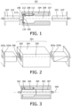
- Figure 1 illustrates an optical fiber connector 101 with a shutter 105, and a separate first group of one or more optical fibers 102 and a separate second group of one or more optical fibers 103.
- the connector 101 may thus be used to mate the first group of one or more optical fibers 102, with one or more corresponding optical fibers in the second group of one or more optical fibers 103.
- the separate groups of optical fibers may be supported by respective ferrules 102', 103'. Consequently an optical path may be formed between corresponding optical fibers in the first and second groups.
- Shutter 105 is illustrated in the closed state in dark shading as item 110 and in an open state in hatched shading as item 111.
- Shutter 105 prevents debris such as dust and sand from entering the connector, which if present in an optical connector would otherwise degrade the lifetime of the connector due to abrasion of the mating optical fiber cores. Furthermore, since the first port 106 is accessed by applying a force, labeled as item F, to the outer surface 113 of the shutter 105; the shutter can be opened with the force of the first group of one or more optical fibers 102 as it is inserted into the first port 106.
- the simplified insertion mechanism facilitates insertion of the first group with a single hand, thereby improving workflow.
- Suitable shutter and body materials include plastics, ceramics and metals.
- An optical fiber is inherently able to deliver light to, and at the same time is also inherently sensitive to light within, a predetermined cone of angles, the cone being aligned axially with the end of the optical fiber. This cone of angles is determined by the numerical aperture, NA, of the optical fiber.
- NA numerical aperture
- An optical fiber with a low NA delivers light to, and is sensitive to, light within a narrow angular range, thus a narrow cone angle, whereas higher NA optical fibers are associated with a larger cone angle.
- an optical fiber delivers light to and is sensitive to light that is aligned with the optical fiber's axis.
- the shutter lies in a plane that perpendicularly intersects the common axis, but providing this intersection is within approximately 5 degrees either side of perpendicular, substantially the same effect will be achieved.
- the inner surface of the shutter has non-zero reflectance within at least a first calibration wavelength interval; a situation which is satisfied by almost all practical materials.
- the reflectance of the inner surface exceeds 1%, or exceeds 10 %, or exceeds 50 %, at a predetermined wavelength within at least a first calibration wavelength interval.
- the calibration wavelength interval may for example be the visible spectrum, the infrared spectrum, or the UV spectrum, or any combination thereof.
- the inner surface 112 of the shutter 105 inherently allows optical fiber connector 101 to be used to calibrate the transmission of an optical fiber.
- a second group of one or more optical fibers 103 should be inserted into the second port 107 of connector 101 in Figure 1 and the shutter should be in the closed state.
- At least one optical fiber within the second group 103 should deliver radiation, i.e. UV, visible or infrared light into cavity 108, and the light collected by the at least one optical fiber within the second group 103 should be detected, for example using a spectrometer, or an optical detector.
- the amount, or the spectrum of the light coupled into the delivery optical fiber may then be compared to that returned by the collecting optical fiber in order to calibrate the optical path.
- the shutter 105 of the optical fiber connector 101 serves both to prevent the ingress of debris, and facilitates an optical calibration procedure without the need for a separate optical reference surface such as the prior art calibration cap.
- the ability to reuse the same inner surface of the shutter as an optical calibration surface for consecutive calibration procedures is advantageous furthermore because it permits successive calibrations with the same optical reference surface. This effect is not achieved by the prior art calibration cap, which is typically discarded following a single use. Thus a more reliable calibration procedure is achieved by using the inner surface of the shutter as an optical calibration surface.
- the inner surface 112 of the shutter 105 has a predetermined optical signature within at least a first calibration wavelength interval, wherein the predetermined optical signature is selected from the group: a diffuse reflectance spectrum, a specular reflectance spectrum, a Raman scattering spectrum, a fluorescence emission spectrum.
- the predetermined optical signature is selected from the group: a diffuse reflectance spectrum, a specular reflectance spectrum, a Raman scattering spectrum, a fluorescence emission spectrum.
- any of these predetermined optical signatures, or a combination thereof may advantageously be used to calibrate the optical transmission of one or more optical fibers in second group 103 when inserted into second port 107. This may be achieved by comparing the amount, or the spectrum of the light coupled into the delivery optical fiber with that returned by the collecting optical fiber, and based on the predetermined optical signature.
- the calibration wavelength interval may be within the ultraviolet, the visible or infrared spectral range and is desirably within the spectrum of wavelengths transmitted by the second group of one or more optical fibers.
- the calibration wavelength interval may be single broad band of optical wavelengths, such as for example from 300 nm to 2000nm, from 400 nm to 1700 nm, or from 400 nm to 800 nm; or one or more narrow bands with a wavelength interval of for example 100 nm, or 50nm, or 10 nm.
- a single broad band permits a calibration to be performed over a broad range of wavelengths, whilst a narrower band may provide a predetermined optical signature only within a specific narrow group of wavelengths.
- a diffuse reflectance spectrum may be provided by a scattering surface.
- suitable scattering surfaces include PolyTetraFluoroEthylene, PTFE, ground glass, or roughened plastic surfaces.
- the surface provides a Lambertian reflectance profile.
- a suitable commercially-available material for providing a diffuse reflectance spectrum that includes PTFE is described in U.S. Pat. No. 4,912,720 and sold under the trademark SPECTRALON by Labsphere, Inc., North Sutton, N.H. This material is known to provide an excellent diffuse reflection spectrum with which the desired optical path calibration can be made.
- SPECTRALON by Labsphere, Inc., North Sutton, N.H. This material is known to provide an excellent diffuse reflection spectrum with which the desired optical path calibration can be made.
- a layer thickness of preferably 5 mm or more should be used in order to provide repeatable diffuse reflectance measurements.
- a specular reflectance spectrum may be provided by a polished surface, such as a polished metal layer, for example a chrome, silver or gold layer, or a polished plastic or glass surface.
- BK7 glass for example is known to have a reflectance of approximately 4% across a substantial part of the visible wavelength range.
- Multilayer optical coatings may also be used to generate the desired specular reflectance spectrum.
- the multilayer coating may furthermore be designed to have a predetermined reflectance within a single broad band, or at one or more narrower bands.
- the multilayer optical coating may be designed to have a specific reflectance such as 50% to red wavelengths, and another specific reflectance such as 10% to green wavelengths. In so doing a calibration optical surface may be provided which tests different parts of the optical spectrum at different points within the dynamic range of an optical detector.
- a coating formed by the process of nano-imprint lithography is also suitable for providing the desired specular reflectance spectrum.
- a Raman scattering spectrum is inherent in many materials and is unique to a particular material.
- a powder coating may be used to provide an enhanced Raman scattering spectrum having a larger reflectance signal.
- a Raman scattering spectrum may be detected by using a laser optical source to irradiate a surface, such as the inner surface of the shutter, and collecting the scattered light on an optical detector. The scattered light that is close in wavelength to the optical source wavelengths is typically indicative of Rayleigh scattering and is filtered out.
- a fluorescence emission spectrum may be provided by including a layer of fluorescent material on the inner surface of the shutter.
- the shutter may be formed from a plastic having a having a fluorescent dye incorporated therein.
- a fluorescence emission spectrum may be particularly suited to calibrating the optical path in fluorescence applications.
- the predetermined optical signature may furthermore be used to determine whether the shutter is in the open state or in the closed state. With reference to Figure 1 , this may be achieved by comparing the amount, or the spectrum of the light that is coupled into a delivery optical fiber within second group 103 when it is inserted into second port 107, to that returned by a collecting optical fiber within second group 103.
- a predictable signal based on the predetermined optical signature will be detected, whereas any deviation from this predicted signal is indicative of the shutter being in the open state.
- This may subsequently be used as part of an automatic calibration procedure, wherein a method routine executed by a computer is configured to perform a calibration procedure with the shutter in the closed state, and is configured to perform an optical signal measurement procedure when the shutter is in the open state.
- the inner surface of the shutter may have a predetermined reflectance value for red optical wavelengths.
- the closed state may be determined by measuring the signal returned by the collecting optical fiber with an optical detector or a spectrometer, the closed state being confirmed when the reflectance of red optical wavelengths corresponds to that expected from the predetermined reflectance value.
- the same effect may be achieved by using a fluorescent, or a diffuse reflecting coating on the inner surface of the shutter.
- the predetermined optical signature may furthermore be associated with a particular type of connector. Consequently by comparing the amount, or the spectrum of the light coupled into the delivery optical fiber, to that returned by the collecting optical fiber, and based on the predetermined optical signature, the particular type of connector that is connected to an optical fiber may be determined. In one example configuration this may be achieved by ensuring that the inner surface of the shutter has, for example have a predetermined reflectance at red and at green optical wavelengths, the particular ratio of the red reflectance to the green reflectance being indicative of a particular connector type.
- an optical detector or optical analyzer such as a spectrometer may be used to analyze the return light in order to determine which specific connector selected from a plurality of optical connectors each having an associated predetermined reflectance, is connected to an optical fiber.
- the predetermined optical signature may furthermore be associated with a particular type of first group of one or more optical fibers.
- the predetermined optical signature being associated with a specific type of ferrule or a specific type of first group of one or more optical fibers, the same technique can be used to identify which first group from of a plurality of first groups of optical fibers are being inserted into the connector. This can be achieved by measuring or analyzing the return light as described above during insertion of the first group into the first port.
- both the body 104 and the shutter 105 of the optical fiber connector 101 in Figure 1 are opaque to optical wavelengths within the at least a first calibration wavelength interval.
- the shutter 105 preferably blocks the first port 106 in the closed state 110 to form a light-impermeable barrier between the first port 106 and the cavity 108.
- a connector is provided which is suitable for performing a detector dark current calibration procedure for an optical detector which is in optical communication with an optical fiber within the second group 103 when occupies the second port 107.
- the ability to perform a detector dark current calibration is advantageous in optical test and calibration instruments as it allows a baseline offset signal that is generated by the detector dark current to be subtracted from a measured optical signal. This finds particular application in spectral tissue sensing applications, permitting a baseline dark spectrum to be subtracted from subsequently measured spectra, thereby improving the subsequent analysis of the tissue type.
- Suitable materials for the body and the shutter include plastics and metals.
- Figure 2 illustrates a perspective view of an optical fiber connector 201 having a shutter 205.
- Optical fiber connector 201 has a common axis 209 which is shared by first port 206 and a second port, not shown.
- Shutter 205 is shown in the closed state.
- Connector 201 may be used to make optical communication between optical fiber 202a in a first group of two optical fibers 202a, 202b, and corresponding optical fiber 203a in a second group of two optical fibers 203a, 203b.
- Optical fibers 202b and 203b may likewise be connected with optical fiber connector 201.
- Figure 3 illustrates an optical fiber connector having a shutter 305 in the open state with a first group of one or more optical fibers 302 received within a first port 306 of the connector and a second group of one or more optical fibers 303 received within a second port 307 of the connector.
- First port 306 and second port 307 share a common axis 309. In so doing, an optical path is formed between corresponding optical fibers in the first group 302 and the second group 303.
- the coupling faces of the corresponding optical fibers are shown as touching, however, in some configurations it is contemplated to separate corresponding optical fibers with an air gap or a positive lens, such as a ball lens, in order to relax the alignment tolerance requirements for the optical fibers.
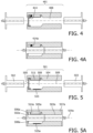
- Figure 4 illustrates an optical fiber connector 401 having mechanically resistive means 414 configured to provide a restoring force to counteract movement of the shutter from the closed state towards the open state.
- Figure 4A illustrates an optical fiber connector having a shutter in the open state, with a first group of optical fibers received within a first port of the connector and a second group of optical fibers received within a second port of the connector, together with mechanically resistive means 414a configured to provide a restoring force to counteract movement of the shutter from the closed state towards the open state.
- the mechanically resistive means 414, 414a is in mechanical communication with the shutter and the body in Figures 4, 4A .
- the mechanically resistive means which may for example be a spring, a compressive member such as a rubber rod, an elastic or rubber band, an elastically deformable blade, or indeed any deformable member configured to provide a restoring force, is configured to provide a restoring force to the shutter to prevent movement of the shutter between the closed state and the open state.
- the mechanically resistive means ensures that the shutter remains reliably closed in the closed state when the first port is unoccupied. This further improves the reliability of the shutter at preventing the ingress of debris, and reliably keeps the shutter in the desired closed state during an optical calibration procedure.
- Figure 5 illustrates an optical fiber connector 501 having a debris collection zone 515.
- Figure 5A illustrates an optical fiber connector having a debris collection zone 515a wherein the connector has a first group of optical fibers 502a received within a first port 506a of the connector and a second group of optical fibers 503a received within a second port 507a of the connector.
- Debris collection zone 515, 515a is within the cavity 508, 508a respectively, and is formed from either a sticky surface or an electrostatically charged surface.
- any dust or sand or particulates that enter the cavity become trapped at the debris collection zone where they are immobilized.
- the lifespan of the connector is thereby improved because debris is prevented from abrading the optical mating surfaces of optical fibers mated by the connector. In particular the number of connector mating cycles is improved in this way.
- Figure 6 illustrates an optical fiber connector 601 having first retaining means 616 for retaining a first group 602 of one or more optical fibers in a first port 606 of the connector 601 and second retaining means 618 for retaining a second group 603 of optical fibers in a second port 607 of the connector 601.
- Shutter 605 is in the closed state 610.
- Figure 6A illustrates an optical fiber connector having first and second retaining means wherein the connector has a first group of optical fibers received within a first port of the connector and a second group of optical fibers received within a second port of the connector.
- the shutter is in the open state 611a.
- the exemplary retaining means shown is a snap-connection retaining means, it may alternatively be provided by for example a friction fit, a screwthread, or a bayonet fitting.
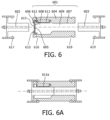
- Figure 7 illustrates an optical fiber connector arrangement 720 comprising an optical fiber connector and a second group of optical fibers 703 received within a second port 707 of the connector, wherein the shutter 705 of the connector is in the closed state 710.
- the second group of one or more optical fibers 703 is received within the second port 707 such that when delivery light 721 emitted by the one or more optical fibers in the second group 703 into the cavity 708 is incident upon the inner surface 712 of the shutter 705 in the closed state 710, return light 722 that is scattered or reflected or emitted by the inner surface 712 of the shutter 705 consequent to the emitted delivery light is at least partially collected by the one or more optical fibers in the second group 703.
- Such an arrangement may advantageously be used to calibrate the transmission of the optical path of the one or more optical fibers in the second group 703.
- Such an arrangement may furthermore be used to perform a dark calibration of an optical detector connected to an optical fiber within the second group 703 of optical fibers by arranging that the body 704 and the shutter 705 are opaque to optical wavelengths within at least a first calibration wavelength interval, and by arranging that the shutter 705 blocks the first port 706 in the closed state 710 to form a light-impermeable barrier between the first port 706 and the cavity 708.
- Figure 8 illustrates an optical fiber connector arrangement 828 comprising an optical fiber connector, a second group of optical fibers 803 received within the second port 807 of the connector, an optical source 829 and a spectrometer 830, wherein the shutter 805 of the connector is in the closed state 810.
- the second group 803 includes a second group delivery optical fiber 831and a second group return optical fiber 832. Furthermore the second group delivery optical fiber 831 is in optical communication with the optical source 829 and the second group return optical fiber 832 is in optical communication with the spectrometer 830.
- the shutter 805 is in the closed state 810 such that the second group delivery optical fiber 831 and the second group return optical fiber 832 form an optical path between the source 829 and the spectrometer 830 that includes the inner surface 812 of the shutter 805.
- the inner surface of the shutter faces the distal ends of both the second group delivery optical fiber 831 and the second group return optical fiber 832.
- the arrangement defines a configuration in which the inner surface of the shutter may be used as an optical reference surface with which to calibrate the optical transmission of the second group delivery optical fiber and the second group return optical fiber, based on the optical properties of the inner surface.
- Suitable spectrometers include grating, prism-based, or interferometer-based spectrometers such as Fourier Transform Infrared, as well as optical detectors that do not discriminate an optical reading based on wavelength and which thus generate a signal indicative of the total energy across a portion of the optical spectrum.
- optical detectors include solid state semiconductor detectors, for example Silicon and InGaAs detectors, as well as photomultiplier tube (PMT) detectors.
- Suitable optical sources include solid state sources such as LEDs and lasers, and filament-based lamps and discharge lamps, many of which are available for generation of an optical signal within the UV, visible and infrared optical spectrum.
- the minimum condition for use of this arrangement to collect a signal with the second group return optical fiber is that the shutter has a non-zero reflectance. Since this requirement is met by almost all practical materials the shutter may perform the desired optical calibration with no special requirements on the inner surface.
- the reflectance of the inner surface exceeds 1%, or exceeds 10 %, or exceeds 50 % at a predetermined wavelength within at least a first calibration wavelength interval.
- the inner surface of the shutter may alternatively have a predetermined optical signature within at least a first calibration wavelength interval, wherein the predetermined optical signature is selected from the group: a diffuse reflectance spectrum, a specular reflectance spectrum, a Raman scattering spectrum, a fluorescence emission spectrum.
- the open and closed states of the shutter, and also the presence of a particular type of connector may be determined based on the predetermined optical signature of the inner surface of the shutter by delivering light from optical source 829 to the inner surface 812 of the shutter via second group delivery optical fiber 831, and measuring the light collected from the inner surface of the shutter by second group return optical fiber 832 with spectrometer 830, or an optical detector in place of spectrometer 830, and comparing the collected light with the light expected, based on the predetermined optical signature.
- the particular type of the first group of one or more optical fibers that is being inserted into the first port may likewise be determined using this configuration by associating a specific optical signature with the ferrule or the first group of optical fibers as described above.
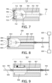
- Figure 9 illustrates an optical fiber connector arrangement 923 comprising an optical fiber connector, a second group of optical fibers 903 received within a second port 907 of the connector, and a first group of optical fibers 902 received within a first port 906 of the connector, wherein the shutter of the connector is in the open state 911.
- the first group 902 is received within the first port 906 such that the first group at least partially fills the cavity 908.
- the first group is arranged respective the second group such that each optical fiber (924, 925) in the first group 902 is in optical communication with one or more corresponding optical fibers (926, 927) in the second group 903.
- Corresponding optical fibers in the first group and the second group may be mated such that their end faces are touching, thus in a so-called butt-coupled arrangement, and are optionally furthermore axially pressed together by applying opposing axial forces along the axis of each optical fiber to ensure that reliable mating is achieved.
- the end faces of the optical fibers may be separated by either an air gap or a positive lens, both of which help to reduce variations in transmission that are caused by misalignment of the optical fiber cores.
- the shutter being openable by applying a force to the outer surface of the shutter in a direction along the common axis allows the rapid conversion of the connector between a closed state in which dust or light is prevented from entering the connector, or in which an optical calibration or dark measurement can be carried out, and a connected state in which optical communication between corresponding optical fibers in the first and second groups is achieved.
- this simple conversion can be carried out by a user with one hand, and without the need for a separate calibration surface, thereby improving workflow during a calibration procedure.
- Figure 10 illustrates an optical fiber connector arrangement 1033 comprising an optical fiber connector, a second group of optical fibers 1003 received within the second port 1007 of the connector, a first group of optical fibers 1002 received within the first port 1006 of the connector, an optical source 1029, a spectrometer 1030, and an optical probe 1034, wherein the shutter of the connector is in the open state 1011.
- the first group of one or more optical fibers 1002 at least partially fills the cavity 1008.
- the first group of one or more optical fibers is arranged respective the second group such that each optical fiber in the first group 1002 is in optical communication with one or more corresponding optical fibers in the second group 1003.
- the first group 1002 includes a first group delivery optical fiber 1035 and a first group return optical fiber 1036
- the second group 1003 includes a second group delivery optical fiber 1031 and a second group return optical fiber 1032.
- the first group delivery optical fiber and the first group return optical fiber each have a distal end located at the distal end 1037 of the optical probe 1034.
- the second group delivery optical fiber 1031 and the first group delivery optical fiber 1035 form an optical path between the optical source 1029 and the distal end 1037 of the optical probe 1034.
- the first group return optical fiber 1036 and the second group return optical fiber 1032 form an optical path between the distal end 1037 of the optical probe 1034 and the spectrometer 1030.
- the arrangement may be used to perform optical measurements at the distal end of the optical probe.
- the optical probe may be any optical probe such as a probe used to inspect material properties or to measure the optical properties of a surface.
- suitable optical probes in the medical field include a needle, a cutting tool such as a surgical knife, a tissue bonding tool. Whilst two separate optical fibers are illustrated in Figure 10 for performing the delivery and return of the optical light from the optical source, these functions may alternatively be combined into a single optical fiber, or their functionality distributed across a plurality of optical fibers.
- the second group delivery optical fiber 1031 has the same core diameter and numerical aperture as the first group delivery optical fiber 1035, and the second group return optical fiber 1032 has the same core diameter and numerical aperture as the first group return optical fiber 1036.
- the alignment tolerance between the first group 1003 and the second group 1002 is relaxed i) the second group delivery optical fiber (1031) has a numerical aperture (NA2D) that exceeds the first group delivery optical fiber (1035) numerical aperture (NA1D), or ii) the second group delivery optical fiber (1031) has a core diameter (D2D) that exceeds the first group delivery optical fiber (1035) core diameter (D1D), or iii) the second group return optical fiber (1032) has a numerical aperture (NA2R) that exceeds the first group return optical fiber (1036) numerical aperture (NAIR), or iv) the second group return optical fiber (1032) has core diameter (D2R) that exceeds the first group return optical fiber (1036) core diameter (D1R).
- the ratio of the two parameters is preferably 1.1 or more, or 1.2 or more, or 1.5 or more. This principle applies in an analogous way to the arrangement of Figure 9 .
- the numerical aperture defines the cone angle of both the beam of light emitted by an optical fiber, and the cone angle of the sensitivity of an optical fiber. It may be adjusted by adjusting the refractive index of the core and the cladding of the optical fiber.
- the alignment tolerance is relaxed.
- This arrangement is not limited to use in a specific field and may be used in any optical interconnection field such as telecommunications, and the optical test and measurement field.
- One example apparatus to which the first group may be connected is an optical probe, wherein the optical probe may be connected directly to the first group of one or more optical fibers to facilitate its disposal together with the first group, whereas a re-usable apparatus such as a measurement console may be connected to the second group of one or more optical fibers.
- suitable optical probes in the medical field include a needle, a cutting tool such as a surgical knife, a tissue bonding tool.
- a method of calibrating an optical fiber path including the steps of: measuring a reference optical spectrum (S1) with the spectrometer in the optical fiber connector arrangement of Figure 8 ; measuring a signal optical spectrum (S2) with the spectrometer in the optical fiber connector arrangement of Figure 10 ; and computing an adjusted optical spectrum (S3) based on either: i) the difference between the reference optical spectrum (S1) and the signal optical spectrum (S2), or ii) the ratio between the reference optical spectrum (S1) and the signal optical spectrum (S2), at one or more optical wavelengths within the spectral range detected by the spectrometer.
- the method may thus advantageously be used to calibrate the optical path of the first group of one or more optical fibers using the inner surface of the shutter as an optical reference surface, and to correct a subsequently measured signal optical spectrum that is measured with an optical probe.
- the method may for example be used to calibrate the transmission of the optical path.
- Another computer program or computer program product comprises instructions which when executed on a computer cause the computer to determine, based on the predetermined optical signature of the inner surface of the shutter whether the shutter in the optical fiber connector arrangement of Figure 9 or Figure 10 is in the open or closed state.
- the computer program or computer program product may compare the detected optical spectrum with a lookup table of spectra associated with specific shutter types in order to determine whether the connector or its open or closed stat, or its type.
- Another computer program or computer program product comprises instructions which when executed on a computer cause the computer to determine, based on the predetermined optical signature of the mating surface of first group of one or more optical fibers, or of the mating surface of a ferrule supporting the first group of one or more optical fibers, which type of first group of one or more optical fibers from a plurality of types of first group of one or more optical fibers associated with a predetermined optical signature, is in the cavity of the optical fiber connector.
- a lookup table may store the association between each type of first group of one or more optical fibers and its predetermined optical signature. The lookup table may be consulted during the determination process.
- This computer program or computer program product may be used with the arrangement of Figure 9 or Figure 10 .
- Another computer program or computer program product comprises instructions which when executed on a computer cause the computer to generate either: i) a reference optical spectrum S1 with the optical fiber connector arrangement of Figure 8 , or to ii) to generate a signal optical spectrum S2 with the spectrometer in the optical fiber connector arrangement of Figure 10 .
- the computer program or computer program product thus permits the automatic acquisition of a spectrum based on the closed or open status of the shutter. Subsequent analysis of the spectra may be used to either interpret the type or nature of the material at the distal end of an optical probe, or to correct the signal optical spectrum based on the reference optical spectrum.
- Another computer program or computer program product comprises instructions which when executed on a computer cause the computer to perform the following steps: identify, based on the predetermined optical signature of the inner surface of the shutter, whether the shutter of the optical connector arrangement of Figure 8 is in the closed state; measure a reference optical spectrum (S1) with the spectrometer in the optical fiber connector arrangement of Figure 8 when the shutter is in the closed state; identify, based on the predetermined optical signature of the inner surface of the shutter, whether the shutter of the optical connector arrangement of Figure 10 is in the open state; and to measure a signal optical spectrum (S2) with the spectrometer in the optical fiber connector arrangement of Figure 10 when the shutter is in the open state; and to compute an adjusted optical spectrum (S3) based on either: i) the difference between the reference optical spectrum (S1) and the signal optical spectrum (S2), or ii) the ratio between the reference optical spectrum (S1) and the signal optical spectrum (S2) at one or more optical wavelengths within the spectral range detected by the spectrometer; wherein each of the above steps: identify,
- the computer program or computer program product may thus advantageously automatically measure a reference spectrum and a signal optical spectrum based on the closed or open status of the shutter, and to use the reference spectrum to re-compute the signal optical spectrum, thereby improving the accuracy of the measured spectrum.
- Advantageously workflow is improved since an operator simply needs to remove the first group of one or more optical fibers from the connector in order to perform a calibration, and connect the first group to perform a signal measurement.
- FIG 11 illustrates an embodiment of a ferrule 1103' for supporting a group of one or more optical fibers 1103.
- the ferrule may be used to support the optical fibers such that they may be inserted into the first or second port 106, 107 of the optical fiber connector in Figure 1 .
- Ferrule 1103' may be formed from a moulded plastic for example.
- the optical fibers may be secured into the ferrule with epoxy, for example, or another adhesive.
- Ferrule 1103' includes an optional spring portion 1139 which when compressed provides an axial force along the axis of the ferrule in order to maintain good contact between abutting ferrules.
- Axial spring portion 1139 may for example be molded into the ferrule itself, or provided by a separate spring.
- Ferrule 1103' includes optional alignment holes 1138 which mate with complementary alignment pins in a corresponding ferrule such that an optical interconnection is formed within optical fiber connector 101 of Figure 1 .
- These alignment features improve the alignment accuracy of the corresponding optical fibers when mated.
- Two identical alignment features are shown in Figure 11 ; however the alignment features may have different shapes or be positioned at different distances from the centerline of the ferrule in order to ensure that the connector can only be connected to a mating part in one orientation.
- Figure 12 illustrates another embodiment of a ferrule 1203' having a ferrule housing 1240.
- the ferrule of Figure 12 may be used to mate with the ferrule of Figure 11 .
- Optional ferrule housing 1240 includes a ferrule housing portion that extends beyond the end face of the optical fibers in order to protect them during insertion into the first port via the shutter of the optical fiber connector in Figure 1 .
- Housing 2140 in Figure 12 includes optional shield 1241 for improving grip and presenting a physical barrier to contact between a gloved hand holding ferrule 1203'and a gloved hand holding corresponding ferrule 1203', thereby reducing the risk of medical contamination between the two ferrules.
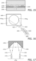
- Figure 13 illustrates an optical fiber connector assembly comprising optical fiber connector 1301, first group of one or more optical fibers 1302 and second group of one or more optical fibers 1303.
- Connector 1301 includes a shutter 1305 which in mounted to the body of the connector via hinge 1342.
- the inner surface of the shutter 1305 includes a white reference surface 1312 for calibrating the first group of optical fibers 1303 received within second port 1307.
- Ferrules 1303', 1303a' support the optical fibers in the second and first groups respectively, and axial spring portion 1339 provides an axial force to maintain good contact between the mating surfaces of the corresponding optical fibers.
- Optional second retaining means provided by snap-action catch 1319 is releasably secured via catch lever 1319a, and is used to temporarily connect housing 1340 of the first group of optical fibers 1302 to second group 1303 in order to effect optical communication therebetween.
- Optional strain relief 1343 relieves the strain on the optical fibers as they exit the second port 1307.
- Figure 14 illustrates another optical fiber connector assembly comprising optical fiber connector 1401 and second group of one or more optical fibers 1403.
- Optional alignment pins 1438a, optional axial spring 1439, optional strain relief 1443, optional snap-action catch 1419 and catch release lever 1419a are also shown.
- Shutter 1405 of connector 1401 is in the closed state such that white reference surface 1412 lies in a plane that transversely intersects a common axis 1409 shared by the first and second port.
- the arrangement of Figure 14 may thus be used to calibrate the optical transmission of the second group of one or more optical fibers 1403 by causing one or more of these optical fibers to emit light into cavity 1408, some of which will, consequent to the orientation of white reference surface 1412, be scattered back into the second group of one or more optical fibers 1403.
- the transmission of the second group of one or more optical fibers may thus be determined by comparing the power or the spectrum of the light inserted into the delivery optical fiber with that collected by the return optical fiber.
- the shutter may be closed by a spring in order to form a light-tight enclosure within the connector and thereby permit a dark spectrum or a dark current measurement.
- the optical reference surface is formed from Spectralon and has a thickness of 5mm to provide a reproducible and accurate white reference surface.
- the interior surface of the shutter may alternatively include an optical reference surface having a predetermined optical signature as described above.
- the shutter is configured to open such that when opened fully there is an air gap between the optical reference surface and the adjacent inner wall of the optical connector facing the shutter such that the optical reference surface is not damaged when opened.
- an optical fiber connector having a shutter, which when closed provides a light-sealed environment within which dark reference measurements can be performed when the optical source is switched off, and which can be used for white reference measurements when the optical source is switched on.
- This facilitates an automatic white reference calibration and the automatic confirmation of when a specific optical cable is connected to the optical path.
- workflow is improved because a calibration procedure does not require a separate optical reference component.
- a more reliable optical calibration is achieved by re-using the same optical reference surface for each calibration procedure.
- the optional asymmetric design of the mating configuration of the optical fibers in the connector prevents erroneous connection of the optical probe.
- ferrule 1303' in Figure 13 may be a re-usable part and formed from a highly durable material such as ceramic or stainless steel for example, whereas mating ferrule 1303a' may be connected to a disposable optical probe such as a photonic needle, the disposable ferrule 1303a' being formed from a plastic ferrule in order to improve the durability and reduce the cost of the disposable portion of the connector.
- One of the main cost drivers for connectors in general is the tolerances that need to be achieved in order to obtain optimal alignment of the optical faces of the fibers that touch at the connector.
- any concentricity errors of the fibers where they touch one another increases attenuation and may result in deviations from the spectral transmission if light is no longer inserted directly from the core, but instead reflects through the cladding onto the buffer and then is re-inserted into the core. In the latter case, the 'color' of the buffer will become visible in the connector's optical transmission spectrum. Because the color of the buffer is often not stable across batches of optical fibers, and because the amount of buffer color inserted into the light is dependent on the amount of light transmitted via the cladding compared to the amount of light transmitted via the core, this can affect the transmission spectrum itself.
- the illumination fiber and the detection fiber in the system cable may be oversized with an amount equal to the worst case tolerances that can be expected in the moulding and assembly process.
- oversizing requires the light source to transmit light from a second group delivery optical fiber into a first group delivery optical fiber, wherein the originating second group delivery optical fiber has a larger diameter.
- a common optical source used in optical sensing application is a halogen light source having a filament. Because the size of the filament of a tungsten halogen light source is typically larger than the diameter of the fiber, increasing the size of this second group delivery optical fiber respective to that of the first group delivery optical fiber has beneficial effects on the amount of light inserted into the second group delivery optical fiber. For example a 400 micron core diameter second group delivery optical fiber may be used in this way to couple light from a halogen source into a smaller, 200 micron core diameter first group delivery optical fiber. The fiber will however also insert light into the cladding because the core of the system cable illumination fiber always fully overlaps the cladding of the optical insert fiber.
- an epoxy based glue may optionally be used to glue the connector into a glass-filled moulded plastic ferrule.
- the epoxy has a higher refractive index than both the cladding material and the core of the illumination fiber, the light leaking into the epoxy will not be guided back into the fiber.
- the glass-filled plastic of the ferrule scatters and absorbs the light that is reflected between cladding and epoxy.
- the ratio of the two parameters is preferably 1.01 or more, or 1.02 or more, or 1.05 or more.
- Figure 15 illustrates a ray path 1544 within an optical fiber passing through a ferrule portion 1545.
- Figure 15 is illustrative of the principle of using an epoxy having a higher refractive index than that of the cladding to secure the optical fiber into the ferrule, and to simultaneously cause light to leak away from the cladding and thereby prevent cladding light from coupling into a mating optical fiber.
- the same principle may also be used in the return optical fiber path to relax its alignment tolerance.
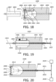
- Figure 16 illustrates an assembly of optical fibers 1603 respective the inner surface 1612 of a shutter 1605 that is in the closed state in which a second group delivery optical fiber 1631 has a delivery optical fiber field of view FOV D that overlaps with the field of view FOV R of a return optical fiber 1632 on the inner surface 1612 of the shutter 1605.
- Figure 16 illustrates in more detail the relative orientations of the optical fibers in the second group 103 of Figure 1 , in particular showing the overlap of the fields of view of these optical fibers when the shutter is in the closed state.
- the field of view of the optical fibers is principally determined by the numerical aperture of each optical fiber, although additional optical components such as a lens or a beamstop may be positioned in the optical path of any of the optical fibers in the second group in order to further control the field of view.
- additional optical components such as a lens or a beamstop may be positioned in the optical path of any of the optical fibers in the second group in order to further control the field of view.
- the overlap between the field of view FOV D of delivery optical fiber 1631and the field of view FOV R of the return optical fiber 1632 ensures that at least a portion of the return light 1622 that is scattered or reflected or emitted by the inner surface 1612 of the shutter 1605 consequent to the emitted delivery light from delivery optical fiber 1631, is collected by the second group return optical fiber 1632.
- radiation i.e.
- FOV D and FOV R there is a substantial overlap between FOV D and FOV R on the inner surface of the shutter, that is to say, on a plane that coincides with the inner surface of the shutter when the shutter is in the closed state, in order to optimize the amount of light collected by return optical fiber 1632.
- the inner surface of the shutter may be used to calibrate the optical path between an optical source in communication with second group delivery optical fiber 1631, and an optical detector in optical communication with second group return optical fiber 1632.
- the overlap between FOV D and FOV R is such that 10% or more, or 20 % or more, or 50 % or more, or 75 % or more, or 90 % or more of the power emitted by delivery optical fiber 1631 falls within the spatial extent of the Full Width Half Maximum (FWHM) of the power sensitivity profile of the second group return optical fiber 1632 on the inner surface 1612 of the shutter.
- the overlap maybe controlled through the lateral separation of the optical fibers 1631, 1632 in Figure 16 .
- optical fibers 1631 and 1632 are adjacent to one another and touching each other in order to achieve a high degree of overlap of the respective field of view.
- the optical fibers may have an increased lateral spacing in order to provide more design freedom whilst at the same time ensuring that a large proportion of the light emitted by optical fiber 1631is collected by return optical fiber 1632.
- Figure 17 is one such configuration having increased lateral spacing.
- the optical fibers may be mutually oriented such that projections of the optical axes of each optical fiber intersect on the inner surface of the shutter in order to improve the amount of light coupling between the delivery optical fiber 1631 and the return optical fiber 1632.
- Figure 17 illustrates an assembly of optical fibers 1703 respective the inner surface 1712 of a shutter 1705 that is in the closed state in which a beam redirector1753 is positioned in the optical path between a second group delivery optical fiber 1731 and a second group return optical fiber 1732.
- delivery light 1721 from optical fiber 1731 is incident on the inner surface of the shutter 1712.
- Return light 1722 that is scattered or reflected or emitted by the inner surface 1712 of the shutter 1705 consequent to the emitted delivery light is redirected by the beam redirector 1753 towards the second group return optical fiber 1732 such that at least a portion of the return light is collected by the second group return optical fiber 1732. In so doing a wider separation between the optical fibers may be used.
- Beam redirector 1753 may be for example a flat surface, a convex or concave curved surface, and may additionally be a mirrored surface, a specular reflecting surface, a scattering surface, or a prism. Such may be used to control, or improve the amount of light collected by second group return optical fiber 1732 consequent to the emitted delivery light.
- Inner surface 1712 may have a predetermined spectral signature, and may be for example a white reference surface, wherein the inner surface of the shutter may be formed from or include a layer of PTFE, Spectralon ® , barium sulphate, or titanium dioxide, or the inner surface may be a wavelength calibration surface.
- the embodiment of Figure 17 may likewise be used to calibrate the optical path between an optical source in communication with delivery optical fiber 1631, and an optical detector in optical communication with second group return optical fiber 1632.
- FIG. 18 illustrates the collection of return light 1822 by a second group return optical fiber in the second group 1803 that is scattered or reflected or emitted by the inner surface 1812 of the shutter 1805 consequent to delivery light emitted by a delivery optical fiber in the second group 1803.
- FIG. 19 illustrates the optical connection between optical fibers 1924 and 1925 in first group of optical fibers 1902 received within the first port 1906 of the optical fiber connector assembly, and corresponding optical fibers 1926 and 1927 in second group of optical fibers 1903 wherein the shutter of the optical fiber connector assembly is in the open state 1911.
- the embodiment of Figure 20 may be used to perform an optical calibration of the optical fiber path between optical source 2029 and spectrometer 2030 In the same manner as described in relation to Figure 8 .
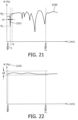
- Figure 21 illustrates an exemplary predetermined optical signature of the inner surface of a shutter that may be used to perform a wavelength calibration of an optical source.
- the predetermined optical signature may be a property of the inner surface of the shutter used throughout this application, exemplarily in the configuration of Figures 10 and 20 , wherein the characteristic peak or trough 2151 of the predetermined optical signature 2150 provides a reference wavelength against which to calibrate the optical source 1029, 2029 or the optical detector 1030, 2030.
- the predetermined optical signature is a diffuse reflectance spectrum and the spectrum is provided by Dysprosium oxide-doped Spectralon ® wavelength calibration standard supplied by Labsphere, North Sutton NH, USA.
- the horizontal axis in Figure 21 represents the wavelength in nanometers and the vertical axis represents the diffuse reflectance.
- the diffuse reflectance 2150 illustrated in Figure 21 has a trough 2151 at wavelength ⁇ 1 within a calibration wavelength interval of 400 nm to 1700 nm with a spectral full width half maximum ⁇ .
- ⁇ is less than or equal to 20nm, more preferably, less than or equal to 10nm, or 5nm. Narrowing the window of ⁇ provides improved accuracy of the wavelength calibration.
- the calibration wavelength interval 400 nm to 1700 nm represents a useful portion of the spectral transmission window of conventional optical fibers.
- the difference between the value Ri of the diffuse reflectance at the trough wavelength at 2151, ⁇ 1 and the diffuse reflectance at a reference value R 2 at wavelength ⁇ 2 that is adjacent to the peak or trough is preferably greater than or equal to 10 %.
- Increasing the difference between R 2 and R 1 to for example greater than or equal to 20 %, or greater than or equal to 50 % further improves the accuracy of the wavelength calibration.
- the predetermined optical signature of Figure 21 may be used to provide a predetermined reference wavelength that can be used to calibrate the optical source or the optical detector.
- Figure 22 illustrates an exemplary predetermined optical signature of the inner surface of a shutter that may be used to calibrate the transmission of an optical fiber.
- the exemplary predetermined optical signature in Figure 22 is a diffuse reflectance spectrum which is substantially constant across the wavelength interval 400 nm to 1700 nm.
- the predetermined optical signature may be used to calibrate the optical transmission of the second group delivery optical fiber 2031 and the second group return optical fiber 2032 using the configuration of Figure 20 .
- the predetermined optical signature may be provided by for example a PTFE layer, or a Spectralon ® layer, or a barium sulphate layer, or a titanium dioxide layer as described hereinbefore.
- the predetermined optical signature provided by the inner surface 112 of the shutter 105 has an average diffuse reflectance value that is greater than or equal to 90 % within the calibration wavelength interval of 400 nm to 1700 nm and a variation in diffuse reflectance value ⁇ R that is less than or equal to 10 % within the calibration wavelength interval of 400 nm to 1700 nm. Narrowing the variation in diffuse reflectance value ⁇ R to less than or equal to 5 %, or to less than or equal to 1 % further improves the accuracy of the calibration.
- an optical fiber connector for mating a first group of one or more optical fibers with one or more corresponding optical fibers in a second group of one or more optical fibers.
- the optical fiber connector includes a shutter, which prevents the ingress of debris into the connector, and provides an optical reference surface with which to calibrate optical fibers that are inserted into the connector.
- the optical fiber connector finds particular application in the medical field wherein it may be used in the interconnection of optical fibers in a photonic needle application.
Landscapes
- Physics & Mathematics (AREA)
- General Physics & Mathematics (AREA)
- Spectroscopy & Molecular Physics (AREA)
- Optics & Photonics (AREA)
- Life Sciences & Earth Sciences (AREA)
- Health & Medical Sciences (AREA)
- General Health & Medical Sciences (AREA)
- Engineering & Computer Science (AREA)
- Pathology (AREA)
- Theoretical Computer Science (AREA)
- Mathematical Physics (AREA)
- Chemical & Material Sciences (AREA)
- Analytical Chemistry (AREA)
- Biochemistry (AREA)
- Immunology (AREA)
- Heart & Thoracic Surgery (AREA)
- Biomedical Technology (AREA)
- Biophysics (AREA)
- Medical Informatics (AREA)
- Molecular Biology (AREA)
- Surgery (AREA)
- Animal Behavior & Ethology (AREA)
- Public Health (AREA)
- Veterinary Medicine (AREA)
- Mechanical Coupling Of Light Guides (AREA)
- Investigating Or Analysing Materials By Optical Means (AREA)
- Optical Couplings Of Light Guides (AREA)
Claims (12)
- Faseroptische Verbinderanordnung (828, 2028), umfassend:eine optische Quelle (829, 2029) und ein Spektrometer (830, 2030); undeine faseroptische Verbinderbaugruppe (1850) zum Zusammenfügen einer ersten Gruppe optischer Fasern (1802), die eine optische Zuleitungsfaser der ersten Gruppe und eine optische Rückleitungsfaser der ersten Gruppe umfasst, mit entsprechenden optischen Fasern in einer zweiten Gruppe optischer Fasern (1603, 1803), die eine optische Zuleitungsfaser der zweiten Gruppe (1631) und eine optische Rückleitungsfaser der zweiten Gruppe (1632) umfasst; wobei die faseroptische Verbinderbaugruppe (1850) einen Körper (1804), eine zweite Gruppe optischer Fasern (1603, 1803), die eine optische Zuleitungsfaser der zweiten Gruppe (1631) und eine optische Rückleitungsfaser der zweiten Gruppe (1632) umfasst, einen Verschluss (1605, 1805) umfasst;wobei der Körper (1804) eine gemeinsame Achse (1809), einen entlang der gemeinsamen Achse (1809) angeordneten Hohlraum (1808), eine erste Öffnung (1806) zum Aufnehmen der ersten Gruppe optischer Fasern (1802) aufweist, wobei sich die erste Öffnung (1806) an einem Ende des Körpers (1804) befindet und sich entlang der gemeinsamen Achse (1809) in den Hohlraum (1808) erstreckt, und wobei die zweite Gruppe optischer Fasern (1603, 1803) am gegenüberliegenden Ende des Körpers (1804) derart angeordnet ist, dass jede Stirnfläche der optischen Fasern in der zweiten Gruppe optischer Fasern (1603, 1803) dem Hohlraum (1808) zugewandt ist;wobei der Verschluss (1605, 1805) mit einem Scharnier an der ersten Öffnung angebracht ist; wobei der Verschluss selektiv zwischen einem geschlossenen Zustand (1810), in dem der Verschluss die erste Öffnung versperrt und in dem der Verschluss in einer Ebene liegt, die die gemeinsame Achse quer schneidet, und einem offenen Zustand (1811), in dem der Verschluss in einer Ebene liegt, die einen spitzen Winkel mit der gemeinsamen Achse bildet, bewegbar ist; undwobei der Verschluss eine Innenfläche (1612, 1812), die sich zuinnerst im Hohlraum befindet, und eine gegenüberliegende Außenfläche (1813) aufweist;wobei der Verschluss durch Aufbringen einer Kraft (F) auf die Außenfläche des Verschlusses in einer Richtung entlang der gemeinsamen Achse zwischen dem geschlossenen Zustand und dem offenen Zustand bewegbar ist; undwobei die zweite Gruppe optischer Fasern (1603, 1803) weiter derart angeordnet ist, dass, wenn sich der Verschluss (1605, 1805) im geschlossenen Zustand (1810) befindet, von der optischen Zuleitungsfaser der zweiten Gruppe (1631) in den Hohlraum (1808) emittiertes Zuleitungslicht (1621, 1821) auf die Innenfläche (1612, 1812) des Verschlusses (1605, 1805) fällt und Rücklicht (1622, 1822), das infolge des emittierten Zuleitungslichts von der Innenfläche des Verschlusses gestreut oder reflektiert oder emittiert wird, mindestens teilweise von der optischen Rückleitungsfaser der zweiten Gruppe (1632) gesammelt wird; undwobei die optische Zuleitungsfaser der zweiten Gruppe (831, 2031) in optischer Kommunikation mit der optischen Quelle (829, 2029) steht und wobei die optische Rückleitungsfaser der zweiten Gruppe (832, 2032) in optischer Kommunikation mit dem Spektrometer (830, 2030) steht;und wobei, wenn sich der Verschluss (805, 2005) im geschlossenen Zustand (810, 2010) befindet, die optische Zuleitungsfaser der zweiten Gruppe (831, 2031) und die optische Rückleitungsfaser der zweiten Gruppe (832, 2032) zwischen der Quelle und dem Spektrometer einen optischen Pfad bilden, der die Innenfläche (812, 2012) des Verschlusses (805, 2005) beinhaltet.
- Faseroptische Verbinderanordnung (101) nach Anspruch 1, wobei der Verschluss (105) derart zwischen dem geschlossenen Zustand (110) und dem offenen Zustand bewegbar ist, dass sich der Verschluss innerhalb des Hohlraums befindet, wenn sich der Verschluss (105) im offenen Zustand (111) befindet.
- Faseroptische Verbinderanordnung nach einem der Ansprüche 1 bis 2, wobei sowohl der Körper als auch der Verschluss für optische Wellenlängen innerhalb mindestens eines ersten Kalibrierungswellenlängenintervalls undurchlässig sind, und wobei der Verschluss im geschlossenen Zustand die erste Öffnung versperrt, um eine lichtundurchlässige Barriere zwischen der ersten Öffnung und dem Hohlraum zu bilden; wobei die lichtundurchlässige Barriere für optische Wellenlängen innerhalb des ersten Kalibrierungswellenlängenintervalls undurchlässig ist.
- Faseroptische Verbinderanordnung nach einem der Ansprüche 1 bis 3, wobei die Innenfläche des Verschlusses eine vorbestimmte optische Signatur innerhalb mindestens eines ersten Kalibrierungswellenlängenintervalls aufweist und wobei die vorbestimmte optische Signatur aus der folgenden Gruppe ausgewählt ist: ein diffuses Reflexionsspektrum, ein Spiegelreflexionsspektrum, ein Raman-Streuspektrum, ein Fluoreszenzemissionsspektrum.
- Faseroptische Verbinderanordnung nach Anspruch 4, wobei die vorbestimmte optische Signatur (2150) mindestens eine Spitze oder mindestens einen Tiefpunkt (2151, λ1) innerhalb des ersten Kalibrierungswellenlängenintervalls von 400 nm bis 1700 nm aufweist; wobei die mindestens eine Spitze oder der mindestens eine Tiefpunkt (2151, λ1) eine spektrale Halbwertsbreite (Δλ) von kleiner als oder gleich 20 nm aufweist, und wobei die Differenz zwischen einem Wert (R1) der optischen Signatur an der Spitze oder dem Tiefpunkt (2151, λ1) und einem Referenzwert (R2) der optischen Signatur bei einer an die Spitze oder den Tiefpunkt angrenzenden Wellenlänge (λ2) größer als oder gleich 10 % ist.
- Faseroptische Verbinderanordnung nach einem der Ansprüche 1 bis 4, wobei die Innenfläche (112) des Verschlusses (105) einen durchschnittlichen diffusen Reflexionswert (2252), der größer als oder gleich 90 % ist, innerhalb eines ersten Kalibrierungswellenlängenintervalls von 400 nm bis 1700 nm und eine Variation des diffusen Reflexionswerts (ΔR), die kleiner als oder gleich 10 % ist, innerhalb des ersten Kalibrierungswellenlängenintervalls von 400 nm bis 1700 nm aufweist.
- Faseroptische Verbinderanordnung nach einem der Ansprüche 1 bis 4, wobei die Innenfläche (112, 1712) des Verschlusses (105, 1705) mindestens einen Strahlumlenker (1753) beinhaltet;
wobei der Strahlumlenker (1753) im optischen Pfad zwischen der optischen Zuleitungsfaser der zweiten Gruppe (1731) und der optischen Rückleitungsfaser der zweiten Gruppe (1732) positioniert ist, wenn sich der Verschluss (705) im geschlossenen Zustand (110) befindet, derart, dass wenn von der optischen Zuleitungsfaser der zweiten Gruppe (1731) emittiertes Zuleitungslicht (1721) die Innenfläche (1712) des Verschlusses (1705) bestrahlt, Rückleitungslicht (1722), das infolge des emittierten Zuleitungslichts von der Innenfläche des Verschlusses gestreut oder reflektiert oder emittiert wird, durch den Strahlumlenker (1753) zu der optischen Rückleitungsfaser der zweiten Gruppe (1632) hin umgelenkt wird. - Faseroptische Verbinderanordnung nach einem der Ansprüche 1 bis 7, die weiter eine Schmutzsammelzone (515) umfasst; wobei die Schmutzsammelzone innerhalb des Hohlraums angeordnet ist und entweder von einer klebrigen Fläche oder einer elektrostatisch geladenen Fläche gebildet wird.
- Faseroptische Verbinderanordnung (923, 1923) nach Anspruch 1, wobei sich der Verschluss im offenen Zustand (911, 1911) befindet, wobei die faseroptische Verbinderanordnung weiter eine erste Gruppe einer oder mehrerer optischer Fasern (902, 1902) beinhaltet;
wobei die erste Gruppe innerhalb der ersten Öffnung (906, 1906) derart aufgenommen ist, dass die erste Gruppe (902, 1902) den Hohlraum (908, 1908) mindestens teilweise ausfüllt;
wobei die erste Gruppe relativ zur zweiten Gruppe derart angeordnet ist, dass jede optische Faser (924, 925, 1924, 1925) in der ersten Gruppe (902, 1902) in optischer Kommunikation mit einer oder mehreren entsprechenden optischen Fasern (926, 927, 1926, 1927) in der zweiten Gruppe (903, 1903) steht. - Faseroptische Verbinderanordnung (1033) nach Anspruch 9, die weiter eine optische Sonde (1034) umfasst;wobei die erste Gruppe (1002) eine optische Zuleitungsfaser der ersten Gruppe (1035) und eine optische Rückleitungsfaser der ersten Gruppe (1036) beinhaltet;wobei die optische Zuleitungsfaser der ersten Gruppe (1035) und die optische Rückleitungsfaser der ersten Gruppe (1036) jeweils ein distales Ende aufweisen, das sich am distalen Ende (1037) der optischen Sonde (1034) befindet; und wobei die optische Zuleitungsfaser der zweiten Gruppe (1031) und die optische Zuleitungsfaser der ersten Gruppe (1035) einen optischen Pfad zwischen der optischen Quelle (1029) und dem distalen Ende (1037) der optischen Sonde (1034) bilden;und wobei die optische Rückleitungsfaser der ersten Gruppe (1036) und die optische Rückleitungsfaser der zweiten Gruppe (1032) einen optischen Pfad zwischen dem distalen Ende (1037) der optischen Sonde (1034) und dem Spektrometer (1030) bilden.
- Verfahren zum Kalibrieren eines faseroptischen Pfades, das die folgenden Schritte umfasst:Messen eines optischen Referenzspektrums (S1) mit dem Spektrometer in der faseroptischen Verbinderanordnung (828) nach Anspruch 1, wenn sich der Verschluss im geschlossenen Zustand befindet;Messen eines optischen Signalspektrums (S2) mit dem Spektrometer in der faseroptischen Verbinderanordnung (1033) nach Anspruch 10, wenn sich der Verschluss im offenen Zustand befindet; undBerechnen eines angepassten optischen Spektrums (S3) auf Basis entweder:i) der Differenz zwischen dem optischen Referenzspektrum (S1) und dem optischen Signalspektrum (S2), oderii) dem Verhältnis zwischen dem optischen Referenzspektrum (S1) und dem optischen Signalspektrum (S2),bei einer oder mehreren optischen Wellenlängen innerhalb des vom Spektrometer erfassten Spektralbereichs.
- Computerprogramm, das Anweisungen umfasst, die, wenn sie auf einem Computer ausgeführt werden, bewirken, dass der Computer die folgenden Schritte durchführt:Identifizieren, auf Basis der vorbestimmten optischen Signatur der Innenfläche des Verschlusses, ob sich der Verschluss der optischen Verbinderanordnung (828) nach Anspruch 4 im geschlossenen Zustand befindet;Empfangen eines optischen Referenzspektrums (S1), das mit dem Spektrometer in der faseroptischen Verbinderanordnung (828) nach Anspruch 1 gemessen wird, wenn sich der Verschluss im geschlossenen Zustand befindet;Identifizieren, auf Basis der vorbestimmten optischen Signatur der Innenfläche des Verschlusses, ob sich der Verschluss der optischen Verbinderanordnung (1033) nach Anspruch 10 im offenen Zustand befindet;Empfangen eines optischen Signalspektrums (S2), das mit dem Spektrometer in der faseroptischen Verbinderanordnung (1033) nach Anspruch 10 gemessen wird, wenn sich der Verschluss im offenen Zustand befindet; undBerechnen eines angepassten optischen Spektrums (S3) auf Basis entweder:i) der Differenz zwischen dem optischen Referenzspektrum (S1) und dem optischen Signalspektrum (S2), oderii) dem Verhältnis zwischen dem optischen Referenzspektrum (S1) und dem optischen Signalspektrum (S2) bei einer oder mehreren optischen Wellenlängen innerhalb des vom Spektrometer erfassten Spektralbereichs;wobei jeder der obigen Schritte in Zusammenhang mit denselben faseroptischen Verbinder durchgeführt wird.
Applications Claiming Priority (4)
| Application Number | Priority Date | Filing Date | Title |
|---|---|---|---|
| US201461980164P | 2014-04-16 | 2014-04-16 | |
| EP14167748 | 2014-05-09 | ||
| EP14198423 | 2014-12-17 | ||
| PCT/EP2015/057435 WO2015158564A1 (en) | 2014-04-16 | 2015-04-07 | Optical fiber calibration connector |
Publications (2)
| Publication Number | Publication Date |
|---|---|
| EP3132295A1 EP3132295A1 (de) | 2017-02-22 |
| EP3132295B1 true EP3132295B1 (de) | 2024-12-18 |
Family
ID=54323516
Family Applications (1)
| Application Number | Title | Priority Date | Filing Date |
|---|---|---|---|
| EP15714504.6A Active EP3132295B1 (de) | 2014-04-16 | 2015-04-07 | Faseroptischer kalibrierungsverbinder |
Country Status (4)
| Country | Link |
|---|---|
| US (1) | US10094768B2 (de) |
| EP (1) | EP3132295B1 (de) |
| CN (1) | CN106255908B (de) |
| WO (1) | WO2015158564A1 (de) |
Families Citing this family (8)
| Publication number | Priority date | Publication date | Assignee | Title |
|---|---|---|---|---|
| US11005000B2 (en) * | 2013-12-09 | 2021-05-11 | Avago Technologies International Sales Pte. Limited | Connector for photonic device |
| GB201701355D0 (en) | 2017-01-27 | 2017-03-15 | Renishaw Plc | Direct laser writing and chemical etching |
| WO2019079326A1 (en) * | 2017-10-17 | 2019-04-25 | Commscope Technologies Llc | SHUTTER CONFIGURATION FOR AN OPTICAL FIBER CONNECTOR PORT WITH MODULAR FIBER SUPPORTS; AND CONNECTION SYSTEM |
| US12072538B2 (en) | 2019-01-18 | 2024-08-27 | Sony Group Corporation | Optical connector |
| JP6890631B2 (ja) * | 2019-06-06 | 2021-06-18 | 京セラ株式会社 | 光ファイバー給電システムの光コネクタ及び給電装置並びに光ファイバー給電システム |
| CN112610581B (zh) * | 2020-12-15 | 2025-02-14 | 奥谱天成(厦门)光电有限公司 | 一种超微量分光光度计的测试孔校准装置及校准方法 |
| US12251190B2 (en) | 2022-10-13 | 2025-03-18 | Canon U.S.A., Inc. | NIRAF calibration sheath phantom |
| CN115508307A (zh) * | 2022-10-14 | 2022-12-23 | 中国人民解放军军事科学院国防科技创新研究院 | 一种太赫兹超表面传感器及太赫兹透射频谱确定方法 |
Citations (6)
| Publication number | Priority date | Publication date | Assignee | Title |
|---|---|---|---|---|
| US4708432A (en) * | 1983-08-11 | 1987-11-24 | Stiftelsen For Industriell Og Teknisk Forskning Ved Norges Tekniske Hogskle (Sintef) | Fiber optic connector including automatic wiping mechanism |
| EP1037078A1 (de) * | 1999-03-08 | 2000-09-20 | Diamond SA | Schutzelement zum Abdecken der Lichtaustrittsfläche an einem optischen Bauteil, insbesondere an einem optischen Stecker |
| US6254282B1 (en) * | 1998-05-27 | 2001-07-03 | Sharp Kabushiki Kaishi | Optical transmit-receive module, optical transmit-receive coupler and optical transmit-receive system using same |
| EP1122565A1 (de) * | 2000-02-04 | 2001-08-08 | Molex Incorporated | Faseroptische Verbindungsbuchse |
| US20040052473A1 (en) * | 2002-09-03 | 2004-03-18 | The Furukawa Electric Co., Ltd. | Optical fiber connector part |
| WO2010024859A1 (en) * | 2008-08-29 | 2010-03-04 | Corning Cable Systems Llc | Fiber optic adapters with integrated shutter |
Family Cites Families (6)
| Publication number | Priority date | Publication date | Assignee | Title |
|---|---|---|---|---|
| US4050450A (en) | 1976-03-05 | 1977-09-27 | American Optical Corporation | Reflection standard for fiber optic probe |
| US4912720A (en) | 1988-10-27 | 1990-03-27 | Labsphere, Inc. | Laser cavity material |
| EP1481226A2 (de) * | 2002-03-06 | 2004-12-01 | Advanced Photometrics, Inc. | Verfahren und vorrichtung zur strahlungscodierung und analyse |
| US7005623B2 (en) | 2003-05-15 | 2006-02-28 | Ceramoptec Industries, Inc. | Autocalibrating medical diode laser system |
| US7365856B2 (en) * | 2005-01-21 | 2008-04-29 | Carl Zeiss Meditec, Inc. | Method of motion correction in optical coherence tomography imaging |
| WO2007112449A2 (en) * | 2006-03-28 | 2007-10-04 | The Regents Of The University Of California | Apparatus and method for raman spectroscopy and microscopy with time domain spectral analysis |
-
2015
- 2015-04-07 EP EP15714504.6A patent/EP3132295B1/de active Active
- 2015-04-07 US US15/301,898 patent/US10094768B2/en active Active
- 2015-04-07 WO PCT/EP2015/057435 patent/WO2015158564A1/en not_active Ceased
- 2015-04-07 CN CN201580019929.1A patent/CN106255908B/zh active Active
Patent Citations (6)
| Publication number | Priority date | Publication date | Assignee | Title |
|---|---|---|---|---|
| US4708432A (en) * | 1983-08-11 | 1987-11-24 | Stiftelsen For Industriell Og Teknisk Forskning Ved Norges Tekniske Hogskle (Sintef) | Fiber optic connector including automatic wiping mechanism |
| US6254282B1 (en) * | 1998-05-27 | 2001-07-03 | Sharp Kabushiki Kaishi | Optical transmit-receive module, optical transmit-receive coupler and optical transmit-receive system using same |
| EP1037078A1 (de) * | 1999-03-08 | 2000-09-20 | Diamond SA | Schutzelement zum Abdecken der Lichtaustrittsfläche an einem optischen Bauteil, insbesondere an einem optischen Stecker |
| EP1122565A1 (de) * | 2000-02-04 | 2001-08-08 | Molex Incorporated | Faseroptische Verbindungsbuchse |
| US20040052473A1 (en) * | 2002-09-03 | 2004-03-18 | The Furukawa Electric Co., Ltd. | Optical fiber connector part |
| WO2010024859A1 (en) * | 2008-08-29 | 2010-03-04 | Corning Cable Systems Llc | Fiber optic adapters with integrated shutter |
Also Published As
| Publication number | Publication date |
|---|---|
| CN106255908A (zh) | 2016-12-21 |
| US20170108430A1 (en) | 2017-04-20 |
| CN106255908B (zh) | 2019-07-16 |
| WO2015158564A1 (en) | 2015-10-22 |
| US10094768B2 (en) | 2018-10-09 |
| EP3132295A1 (de) | 2017-02-22 |
Similar Documents
| Publication | Publication Date | Title |
|---|---|---|
| EP3132295B1 (de) | Faseroptischer kalibrierungsverbinder | |
| EP0815434B1 (de) | Diffus reflektierende sonde | |
| US3999864A (en) | Gloss measuring instrument | |
| US9915790B2 (en) | Fiber inspection microscope and power measurement system, fiber inspection tip and method using same | |
| CN102047162B (zh) | 检查光纤电缆连接器内的光纤接口的端接质量的方法和装置 | |
| JP6381647B2 (ja) | 光ファイバコネクタ妥当性確認 | |
| US20090190125A1 (en) | Device and Method for Spectrometric System | |
| JPWO2018037958A1 (ja) | 光コネクタ及び光コネクタの製造方法 | |
| WO2016112235A1 (en) | Reflective optical coherence tomography probe | |
| US7929123B2 (en) | Method and apparatus for measuring insertion loss in a fiber optic cable connection | |
| JP5988983B2 (ja) | 校正装置および校正方法 | |
| US20180112965A1 (en) | Optical probe | |
| JPH02114151A (ja) | 屈折率に依存するアパーチャ分布を有する屈折計 | |
| US8456636B2 (en) | Device for detecting signs of bacterial infection of the teeth | |
| US6563992B1 (en) | Small diameter diffuse reflectance probe | |
| US7009692B2 (en) | Arrangement for monitoring the power delivery of a photon channeling element | |
| EP3134757B1 (de) | Anvisierungssystem | |
| EP2032968B1 (de) | Diffuse-reflexion-sonde für optische messungen | |
| US8687184B2 (en) | Reference cell |
Legal Events
| Date | Code | Title | Description |
|---|---|---|---|
| STAA | Information on the status of an ep patent application or granted ep patent |
Free format text: STATUS: THE INTERNATIONAL PUBLICATION HAS BEEN MADE |
|
| PUAI | Public reference made under article 153(3) epc to a published international application that has entered the european phase |
Free format text: ORIGINAL CODE: 0009012 |
|
| STAA | Information on the status of an ep patent application or granted ep patent |
Free format text: STATUS: REQUEST FOR EXAMINATION WAS MADE |
|
| 17P | Request for examination filed |
Effective date: 20161116 |
|
| AK | Designated contracting states |
Kind code of ref document: A1 Designated state(s): AL AT BE BG CH CY CZ DE DK EE ES FI FR GB GR HR HU IE IS IT LI LT LU LV MC MK MT NL NO PL PT RO RS SE SI SK SM TR |
|
| AX | Request for extension of the european patent |
Extension state: BA ME |
|
| DAV | Request for validation of the european patent (deleted) | ||
| DAX | Request for extension of the european patent (deleted) | ||
| STAA | Information on the status of an ep patent application or granted ep patent |
Free format text: STATUS: EXAMINATION IS IN PROGRESS |
|
| PUAG | Search results despatched under rule 164(2) epc together with communication from examining division |
Free format text: ORIGINAL CODE: 0009017 |
|
| 17Q | First examination report despatched |
Effective date: 20190508 |
|
| B565 | Issuance of search results under rule 164(2) epc |
Effective date: 20190508 |
|
| RIC1 | Information provided on ipc code assigned before grant |
Ipc: G02B 6/38 20060101AFI20190503BHEP |
|
| RAP1 | Party data changed (applicant data changed or rights of an application transferred) |
Owner name: KONINKLIJKE PHILIPS N.V. |
|
| GRAP | Despatch of communication of intention to grant a patent |
Free format text: ORIGINAL CODE: EPIDOSNIGR1 |
|
| STAA | Information on the status of an ep patent application or granted ep patent |
Free format text: STATUS: GRANT OF PATENT IS INTENDED |
|
| RIC1 | Information provided on ipc code assigned before grant |
Ipc: G01N 21/27 20060101ALI20240708BHEP Ipc: A61B 5/00 20060101ALI20240708BHEP Ipc: G01J 3/28 20060101ALI20240708BHEP Ipc: G01J 3/02 20060101ALI20240708BHEP Ipc: G02B 6/38 20060101AFI20240708BHEP |
|
| INTG | Intention to grant announced |
Effective date: 20240812 |
|
| GRAS | Grant fee paid |
Free format text: ORIGINAL CODE: EPIDOSNIGR3 |
|
| GRAA | (expected) grant |
Free format text: ORIGINAL CODE: 0009210 |
|
| STAA | Information on the status of an ep patent application or granted ep patent |
Free format text: STATUS: THE PATENT HAS BEEN GRANTED |
|
| AK | Designated contracting states |
Kind code of ref document: B1 Designated state(s): AL AT BE BG CH CY CZ DE DK EE ES FI FR GB GR HR HU IE IS IT LI LT LU LV MC MK MT NL NO PL PT RO RS SE SI SK SM TR |
|
| REG | Reference to a national code |
Ref country code: GB Ref legal event code: FG4D |
|
| REG | Reference to a national code |
Ref country code: CH Ref legal event code: EP |
|
| REG | Reference to a national code |
Ref country code: DE Ref legal event code: R096 Ref document number: 602015090654 Country of ref document: DE |
|
| REG | Reference to a national code |
Ref country code: IE Ref legal event code: FG4D |
|
| REG | Reference to a national code |
Ref country code: LT Ref legal event code: MG9D |
|
| PG25 | Lapsed in a contracting state [announced via postgrant information from national office to epo] |
Ref country code: HR Free format text: LAPSE BECAUSE OF FAILURE TO SUBMIT A TRANSLATION OF THE DESCRIPTION OR TO PAY THE FEE WITHIN THE PRESCRIBED TIME-LIMIT Effective date: 20241218 |
|
| PG25 | Lapsed in a contracting state [announced via postgrant information from national office to epo] |
Ref country code: FI Free format text: LAPSE BECAUSE OF FAILURE TO SUBMIT A TRANSLATION OF THE DESCRIPTION OR TO PAY THE FEE WITHIN THE PRESCRIBED TIME-LIMIT Effective date: 20241218 |
|
| PG25 | Lapsed in a contracting state [announced via postgrant information from national office to epo] |
Ref country code: BG Free format text: LAPSE BECAUSE OF FAILURE TO SUBMIT A TRANSLATION OF THE DESCRIPTION OR TO PAY THE FEE WITHIN THE PRESCRIBED TIME-LIMIT Effective date: 20241218 |
|
| PG25 | Lapsed in a contracting state [announced via postgrant information from national office to epo] |
Ref country code: NO Free format text: LAPSE BECAUSE OF FAILURE TO SUBMIT A TRANSLATION OF THE DESCRIPTION OR TO PAY THE FEE WITHIN THE PRESCRIBED TIME-LIMIT Effective date: 20250318 |
|
| REG | Reference to a national code |
Ref country code: NL Ref legal event code: MP Effective date: 20241218 |
|
| PG25 | Lapsed in a contracting state [announced via postgrant information from national office to epo] |
Ref country code: LV Free format text: LAPSE BECAUSE OF FAILURE TO SUBMIT A TRANSLATION OF THE DESCRIPTION OR TO PAY THE FEE WITHIN THE PRESCRIBED TIME-LIMIT Effective date: 20241218 Ref country code: GR Free format text: LAPSE BECAUSE OF FAILURE TO SUBMIT A TRANSLATION OF THE DESCRIPTION OR TO PAY THE FEE WITHIN THE PRESCRIBED TIME-LIMIT Effective date: 20250319 |
|
| PG25 | Lapsed in a contracting state [announced via postgrant information from national office to epo] |
Ref country code: RS Free format text: LAPSE BECAUSE OF FAILURE TO SUBMIT A TRANSLATION OF THE DESCRIPTION OR TO PAY THE FEE WITHIN THE PRESCRIBED TIME-LIMIT Effective date: 20250318 |
|
| PG25 | Lapsed in a contracting state [announced via postgrant information from national office to epo] |
Ref country code: NL Free format text: LAPSE BECAUSE OF FAILURE TO SUBMIT A TRANSLATION OF THE DESCRIPTION OR TO PAY THE FEE WITHIN THE PRESCRIBED TIME-LIMIT Effective date: 20241218 |
|
| REG | Reference to a national code |
Ref country code: AT Ref legal event code: MK05 Ref document number: 1752682 Country of ref document: AT Kind code of ref document: T Effective date: 20241218 |
|
| PG25 | Lapsed in a contracting state [announced via postgrant information from national office to epo] |
Ref country code: SM Free format text: LAPSE BECAUSE OF FAILURE TO SUBMIT A TRANSLATION OF THE DESCRIPTION OR TO PAY THE FEE WITHIN THE PRESCRIBED TIME-LIMIT Effective date: 20241218 |
|
| PG25 | Lapsed in a contracting state [announced via postgrant information from national office to epo] |
Ref country code: PL Free format text: LAPSE BECAUSE OF FAILURE TO SUBMIT A TRANSLATION OF THE DESCRIPTION OR TO PAY THE FEE WITHIN THE PRESCRIBED TIME-LIMIT Effective date: 20241218 |
|
| PGFP | Annual fee paid to national office [announced via postgrant information from national office to epo] |
Ref country code: DE Payment date: 20250428 Year of fee payment: 11 |
|
| PG25 | Lapsed in a contracting state [announced via postgrant information from national office to epo] |
Ref country code: ES Free format text: LAPSE BECAUSE OF FAILURE TO SUBMIT A TRANSLATION OF THE DESCRIPTION OR TO PAY THE FEE WITHIN THE PRESCRIBED TIME-LIMIT Effective date: 20241218 |
|
| PGFP | Annual fee paid to national office [announced via postgrant information from national office to epo] |
Ref country code: GB Payment date: 20250422 Year of fee payment: 11 |
|
| PG25 | Lapsed in a contracting state [announced via postgrant information from national office to epo] |
Ref country code: IS Free format text: LAPSE BECAUSE OF FAILURE TO SUBMIT A TRANSLATION OF THE DESCRIPTION OR TO PAY THE FEE WITHIN THE PRESCRIBED TIME-LIMIT Effective date: 20250418 |
|
| PG25 | Lapsed in a contracting state [announced via postgrant information from national office to epo] |
Ref country code: PT Free format text: LAPSE BECAUSE OF FAILURE TO SUBMIT A TRANSLATION OF THE DESCRIPTION OR TO PAY THE FEE WITHIN THE PRESCRIBED TIME-LIMIT Effective date: 20250421 |
|
| PG25 | Lapsed in a contracting state [announced via postgrant information from national office to epo] |
Ref country code: EE Free format text: LAPSE BECAUSE OF FAILURE TO SUBMIT A TRANSLATION OF THE DESCRIPTION OR TO PAY THE FEE WITHIN THE PRESCRIBED TIME-LIMIT Effective date: 20241218 |
|
| PG25 | Lapsed in a contracting state [announced via postgrant information from national office to epo] |
Ref country code: AT Free format text: LAPSE BECAUSE OF FAILURE TO SUBMIT A TRANSLATION OF THE DESCRIPTION OR TO PAY THE FEE WITHIN THE PRESCRIBED TIME-LIMIT Effective date: 20241218 Ref country code: RO Free format text: LAPSE BECAUSE OF FAILURE TO SUBMIT A TRANSLATION OF THE DESCRIPTION OR TO PAY THE FEE WITHIN THE PRESCRIBED TIME-LIMIT Effective date: 20241218 |
|
| PG25 | Lapsed in a contracting state [announced via postgrant information from national office to epo] |
Ref country code: SK Free format text: LAPSE BECAUSE OF FAILURE TO SUBMIT A TRANSLATION OF THE DESCRIPTION OR TO PAY THE FEE WITHIN THE PRESCRIBED TIME-LIMIT Effective date: 20241218 |
|
| PG25 | Lapsed in a contracting state [announced via postgrant information from national office to epo] |
Ref country code: CZ Free format text: LAPSE BECAUSE OF FAILURE TO SUBMIT A TRANSLATION OF THE DESCRIPTION OR TO PAY THE FEE WITHIN THE PRESCRIBED TIME-LIMIT Effective date: 20241218 |
|
| PG25 | Lapsed in a contracting state [announced via postgrant information from national office to epo] |
Ref country code: IT Free format text: LAPSE BECAUSE OF FAILURE TO SUBMIT A TRANSLATION OF THE DESCRIPTION OR TO PAY THE FEE WITHIN THE PRESCRIBED TIME-LIMIT Effective date: 20241218 |
|
| PG25 | Lapsed in a contracting state [announced via postgrant information from national office to epo] |
Ref country code: SE Free format text: LAPSE BECAUSE OF FAILURE TO SUBMIT A TRANSLATION OF THE DESCRIPTION OR TO PAY THE FEE WITHIN THE PRESCRIBED TIME-LIMIT Effective date: 20241218 |
|
| REG | Reference to a national code |
Ref country code: DE Ref legal event code: R097 Ref document number: 602015090654 Country of ref document: DE |
|
| PG25 | Lapsed in a contracting state [announced via postgrant information from national office to epo] |
Ref country code: DK Free format text: LAPSE BECAUSE OF FAILURE TO SUBMIT A TRANSLATION OF THE DESCRIPTION OR TO PAY THE FEE WITHIN THE PRESCRIBED TIME-LIMIT Effective date: 20241218 |
|
| PLBE | No opposition filed within time limit |
Free format text: ORIGINAL CODE: 0009261 |
|
| STAA | Information on the status of an ep patent application or granted ep patent |
Free format text: STATUS: NO OPPOSITION FILED WITHIN TIME LIMIT |
|
| REG | Reference to a national code |
Ref country code: CH Ref legal event code: L10 Free format text: ST27 STATUS EVENT CODE: U-0-0-L10-L00 (AS PROVIDED BY THE NATIONAL OFFICE) Effective date: 20251029 |
|
| REG | Reference to a national code |
Ref country code: CH Ref legal event code: H13 Free format text: ST27 STATUS EVENT CODE: U-0-0-H10-H13 (AS PROVIDED BY THE NATIONAL OFFICE) Effective date: 20251125 |
|
| 26N | No opposition filed |
Effective date: 20250919 |
|
| PG25 | Lapsed in a contracting state [announced via postgrant information from national office to epo] |
Ref country code: LU Free format text: LAPSE BECAUSE OF NON-PAYMENT OF DUE FEES Effective date: 20250407 |
|
| PG25 | Lapsed in a contracting state [announced via postgrant information from national office to epo] |
Ref country code: MC Free format text: LAPSE BECAUSE OF FAILURE TO SUBMIT A TRANSLATION OF THE DESCRIPTION OR TO PAY THE FEE WITHIN THE PRESCRIBED TIME-LIMIT Effective date: 20241218 |
|
| PG25 | Lapsed in a contracting state [announced via postgrant information from national office to epo] |
Ref country code: FR Free format text: LAPSE BECAUSE OF NON-PAYMENT OF DUE FEES Effective date: 20250430 |