EP3132220B1 - Heat exchanger for a motor vehicle - Google Patents
Heat exchanger for a motor vehicle Download PDFInfo
- Publication number
- EP3132220B1 EP3132220B1 EP15727303.8A EP15727303A EP3132220B1 EP 3132220 B1 EP3132220 B1 EP 3132220B1 EP 15727303 A EP15727303 A EP 15727303A EP 3132220 B1 EP3132220 B1 EP 3132220B1
- Authority
- EP
- European Patent Office
- Prior art keywords
- heat exchanger
- rims
- core bundle
- fluid
- rim
- Prior art date
- Legal status (The legal status is an assumption and is not a legal conclusion. Google has not performed a legal analysis and makes no representation as to the accuracy of the status listed.)
- Active
Links
Images


Classifications
-
- F—MECHANICAL ENGINEERING; LIGHTING; HEATING; WEAPONS; BLASTING
- F28—HEAT EXCHANGE IN GENERAL
- F28D—HEAT-EXCHANGE APPARATUS, NOT PROVIDED FOR IN ANOTHER SUBCLASS, IN WHICH THE HEAT-EXCHANGE MEDIA DO NOT COME INTO DIRECT CONTACT
- F28D9/00—Heat-exchange apparatus having stationary plate-like or laminated conduit assemblies for both heat-exchange media, the media being in contact with different sides of a conduit wall
- F28D9/0031—Heat-exchange apparatus having stationary plate-like or laminated conduit assemblies for both heat-exchange media, the media being in contact with different sides of a conduit wall the conduits for one heat-exchange medium being formed by paired plates touching each other
- F28D9/0043—Heat-exchange apparatus having stationary plate-like or laminated conduit assemblies for both heat-exchange media, the media being in contact with different sides of a conduit wall the conduits for one heat-exchange medium being formed by paired plates touching each other the plates having openings therein for circulation of at least one heat-exchange medium from one conduit to another
- F28D9/0056—Heat-exchange apparatus having stationary plate-like or laminated conduit assemblies for both heat-exchange media, the media being in contact with different sides of a conduit wall the conduits for one heat-exchange medium being formed by paired plates touching each other the plates having openings therein for circulation of at least one heat-exchange medium from one conduit to another with U-flow or serpentine-flow inside conduits; with centrally arranged openings on the plates
-
- F—MECHANICAL ENGINEERING; LIGHTING; HEATING; WEAPONS; BLASTING
- F02—COMBUSTION ENGINES; HOT-GAS OR COMBUSTION-PRODUCT ENGINE PLANTS
- F02B—INTERNAL-COMBUSTION PISTON ENGINES; COMBUSTION ENGINES IN GENERAL
- F02B29/00—Engines characterised by provision for charging or scavenging not provided for in groups F02B25/00, F02B27/00 or F02B33/00 - F02B39/00; Details thereof
- F02B29/04—Cooling of air intake supply
- F02B29/045—Constructional details of the heat exchangers, e.g. pipes, plates, ribs, insulation, materials, or manufacturing and assembly
- F02B29/0462—Liquid cooled heat exchangers
-
- F—MECHANICAL ENGINEERING; LIGHTING; HEATING; WEAPONS; BLASTING
- F02—COMBUSTION ENGINES; HOT-GAS OR COMBUSTION-PRODUCT ENGINE PLANTS
- F02M—SUPPLYING COMBUSTION ENGINES IN GENERAL WITH COMBUSTIBLE MIXTURES OR CONSTITUENTS THEREOF
- F02M35/00—Combustion-air cleaners, air intakes, intake silencers, or induction systems specially adapted for, or arranged on, internal-combustion engines
- F02M35/10—Air intakes; Induction systems
- F02M35/10242—Devices or means connected to or integrated into air intakes; Air intakes combined with other engine or vehicle parts
- F02M35/10268—Heating, cooling or thermal insulating means
-
- F—MECHANICAL ENGINEERING; LIGHTING; HEATING; WEAPONS; BLASTING
- F28—HEAT EXCHANGE IN GENERAL
- F28F—DETAILS OF HEAT-EXCHANGE AND HEAT-TRANSFER APPARATUS, OF GENERAL APPLICATION
- F28F9/00—Casings; Header boxes; Auxiliary supports for elements; Auxiliary members within casings
- F28F9/001—Casings in the form of plate-like arrangements; Frames enclosing a heat exchange core
-
- F—MECHANICAL ENGINEERING; LIGHTING; HEATING; WEAPONS; BLASTING
- F28—HEAT EXCHANGE IN GENERAL
- F28F—DETAILS OF HEAT-EXCHANGE AND HEAT-TRANSFER APPARATUS, OF GENERAL APPLICATION
- F28F9/00—Casings; Header boxes; Auxiliary supports for elements; Auxiliary members within casings
- F28F9/02—Header boxes; End plates
- F28F9/0219—Arrangements for sealing end plates into casing or header box; Header box sub-elements
-
- F—MECHANICAL ENGINEERING; LIGHTING; HEATING; WEAPONS; BLASTING
- F28—HEAT EXCHANGE IN GENERAL
- F28D—HEAT-EXCHANGE APPARATUS, NOT PROVIDED FOR IN ANOTHER SUBCLASS, IN WHICH THE HEAT-EXCHANGE MEDIA DO NOT COME INTO DIRECT CONTACT
- F28D21/00—Heat-exchange apparatus not covered by any of the groups F28D1/00 - F28D20/00
- F28D2021/0019—Other heat exchangers for particular applications; Heat exchange systems not otherwise provided for
- F28D2021/008—Other heat exchangers for particular applications; Heat exchange systems not otherwise provided for for vehicles
- F28D2021/0082—Charged air coolers
-
- F—MECHANICAL ENGINEERING; LIGHTING; HEATING; WEAPONS; BLASTING
- F28—HEAT EXCHANGE IN GENERAL
- F28F—DETAILS OF HEAT-EXCHANGE AND HEAT-TRANSFER APPARATUS, OF GENERAL APPLICATION
- F28F2230/00—Sealing means
-
- F—MECHANICAL ENGINEERING; LIGHTING; HEATING; WEAPONS; BLASTING
- F28—HEAT EXCHANGE IN GENERAL
- F28F—DETAILS OF HEAT-EXCHANGE AND HEAT-TRANSFER APPARATUS, OF GENERAL APPLICATION
- F28F2275/00—Fastening; Joining
- F28F2275/20—Fastening; Joining with threaded elements
-
- Y—GENERAL TAGGING OF NEW TECHNOLOGICAL DEVELOPMENTS; GENERAL TAGGING OF CROSS-SECTIONAL TECHNOLOGIES SPANNING OVER SEVERAL SECTIONS OF THE IPC; TECHNICAL SUBJECTS COVERED BY FORMER USPC CROSS-REFERENCE ART COLLECTIONS [XRACs] AND DIGESTS
- Y02—TECHNOLOGIES OR APPLICATIONS FOR MITIGATION OR ADAPTATION AGAINST CLIMATE CHANGE
- Y02T—CLIMATE CHANGE MITIGATION TECHNOLOGIES RELATED TO TRANSPORTATION
- Y02T10/00—Road transport of goods or passengers
- Y02T10/10—Internal combustion engine [ICE] based vehicles
- Y02T10/12—Improving ICE efficiencies
Definitions
- the invention relates to a heat exchanger according to the preamble of claim 1, in particular for supplying air to motor vehicle engines, and more particularly to engines whose supply air comes from a compressor or a turbocharger delivering so-called supercharging air.
- a heat exchanger is known to US2013 / 0133866 .
- a charge air cooler has at least one heat exchange bundle.
- heat exchange beams are known comprising a stack of plates alternately forming circulation channels for the supercharged air to be cooled and channels for the circulation of the coolant of the exchanger.
- This exchanger is generally integrated in the intake manifold of the internal combustion engine.
- the efficiency of the heat exchange strongly depends on the level of leakage between the beam and the collector. A bad configuration at this level leads to a decrease of significant performance of the exchanger.
- it is essential to ensure a precise and reproducible beam positioning in the collector to promote proper operation.
- the invention relates to a heat exchanger between a first and a second fluid, having the features of claim 1.
- rim any contour portion of the plate placed transversely in the flow of second fluid, in particular any contour portion of the plate whose function is not the assembly of the plate to the rest of the beam.
- the clearance between the beam and the housing is obstructed by the plates of the beam themselves, through their rim. Thanks to this one, it prevents a direct passage of the second fluid from an inlet to an outlet of the housing without passing through the heat exchange beam. This prevents a fraction of the second fluid from the exchanger without having been cooled.
- the housing is configured to be connected to the intake manifolds of an engine.
- Said heat exchanger notably serves as a charge air cooler for the engine.
- the invention also relates to a vehicle engine intake module comprising a heat exchanger as described above.
- FIGS. 1 and 2 in particular, the invention relates to a heat exchanger 1, in particular for an air supply of a motor vehicle engine, as here.
- the exchanger allows a heat exchange between a first fluid F1 and a second fluid F2.
- the first fluid F1 is a coolant, especially brine
- the second fluid F2 is the charge air, to cool.
- This exchanger 1 thus forms, for example, a charge air cooler integrated into an intake manifold 3 of the internal combustion engine.
- Said heat exchanger 1 comprises at least one heat exchange bundle 5 traversed by the first fluid F1 and a housing 7 in which said heat exchange bundle 5 is housed so as to be traversed by said second fluid F2.
- the heat exchange bundle comprises plates 23 for circulating the first fluid F1 stacked one on the other.
- said plates 23 have one or more flanges 29, as shown in FIGS. Figures 9 and 10 disposed between said heat exchange beam 5 and said housing 7 to limit a bypass of the beam by the second fluid F2.
- the invention limits or even prevents a passage of the second fluid F2 between the heat exchange beam 5 and the housing 7, in particular by creating a pressure drop in the passage.
- Such a characteristic makes it possible to greatly increase the heat efficiency of the exchanger. Indeed, because of the high density of the beam and therefore the consequent pressure drop on the second fluid F2 in the beam, even a small leak between the housing and the beam would cause a large flow of uncooled gas through the beam. exchanger.
- the housing 7 is here configured to be connected to the intake manifolds 11 of the engine. It comprises in particular a protrusion or outlet manifold 13 on one of its large faces, through which it is connected to said intake manifolds 11. An inlet manifold of the second fluid is located at the opposite side.
- Said housing 7 is here closed on one of its faces by a so-called front flange plate 15, to which said heat exchange bundle 5 is sealed, particularly by soldering.
- This front flange 15 is fixed, for example, by screws 17 to the housing 7.
- a not shown seal may be used between said flange 15 and said housing 7 to prevent leakage of second fluid to the outside.
- Said flange 15 further comprises ducts 19 for input and output of the first fluid F1 of the heat exchange bundle. It should be noted that this front flange 15 closes an opening 21 of the housing for the passage of the heat exchange beam 5, when it is mounted in the housing.
- Said heat exchange beam 5 is rectangular parallelepiped here. It comprises a stack of plates 23 alternately forming circulation channels for the first and the second fluid.
- the plates are, for example, assembled in pairs to form circulation channels for the first fluid.
- said channels are configured in U and the first fluid enters and leaves the pairs of plates at orifices located on the same side 31 of the beam 5.
- the orifices of the pairs of plates communicate with each other in pairs to form an inlet manifold and an outlet manifold for the first fluid, respectively communicating with the ducts 19 of the front flange 15.
- Said plates are formed, for example, by stamping, stacked and brazed together.
- the flanges 29 are derived here from sheets, formed by folding, with a single thickness as illustrated in FIGS. Figures 9 and 10 or in double thickness, figure 12 , according to an alternative embodiment. They form in succession an overall rim 30, in particular rectilinear. These flanges could still be attached to the plates, for example by soldering.
- said plates 23 have, for example, lateral edges 50, located at the side faces of the beam. Said lateral edges 50 are derived from the plane of said plates 23, in particular by folding. Here, said side edges 50 of the plates 23 overlap partially from one pair of plates to another.
- Said flanges 29 are derived, advantageously by folding, from said lateral edges 50, in particular lateral edges 50 located internally.
- the rim 29 of one of the plates 23 covers the lateral edge 50 covering the lateral edge 50 which said flange 29 is itself derived.
- the exchange of heat between the plates 23 and the second fluid can be done, in part, through turbulators 25 located between the pairs of plates.
- Said heat exchange bundle 5 is here closed on a large face, opposite to said front flange 15, by a plate called structural plate 27.
- This plate 27 is for example fixed to the beam by soldering. Alternatively, it may be one of the plates of the beam.
- the plates 23 may each have a flange 29 formed projecting from their plane, in particular perpendicular to their plane.
- the flange 29 is here perpendicular to the lateral faces 31 of the beam, namely the faces adjacent to the longitudinal faces 33 of the inlet and the outlet of the air of the beam.
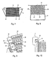
- This or these edges 29, particularly visible to Figures 7 to 10 are preferably arranged in a plurality of identical edges 29 spaced regularly from each other at the pairs of plates.
- the or said flanges 29 are advantageously arranged along the same direction parallel to the stacking direction of the plates. They are located, for example, along an edge 35 of longitudinal face 33 of the beam, here the longitudinal end face of the second fluid.
- said flanges 29 form, as mentioned, an assembly flange along a line d which is here an edge line 35 of said longitudinal face 33 of the second fluid beam outlet.
- Said rims 29 may be extended along said longitudinal face 33 in order to come into contact with the turbulators 25. They thus form a screen preventing the passage of the second fluid at zones of the uncoated plates of said turbulators, which favors the exchange heat.
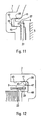
- Said structural plate 27 also comprises at least one edge 37, here a regular edge 37, figure 11 , passing through a plane containing the or said flanges 29 of the plates 23.
- This edge 37 is rectilinear, perpendicular to the plane of the structural plate 27.
- a seal or sealing coating 9 is advantageously mounted along said plate edge (s) 29 beam and / or said edge 37 of structural plate, being attached, for example clipped or glued, to the latter.
- said seal 9 is mounted on said beam plate edges 29 and on said structural plate edge 37, on three sides of the beam 5, as here. It is notably configured with a U-shaped profile, Figures 7 and 8 , to extend longitudinally in continuity on said beam plate edges 29 and said structural plate flange 37, on each of said lateral faces 31 and structural plate 27 of the bundle, until it comes into contact with said flange 15.
- said seal 9 has a regular U-shaped section, figure 3 , capable of allowing the seal to engage or receive said beam plate flanges 29 and said structural plate edge 37.
- the engagement can be relatively tight in order to retain the seal after engagement.
- the profiles of the flanges 29 and 37 are here identical but they may be different, the seal 9 having a complementary profile.
- said seal 9 is able to be fixed, in particular clipped by a hook 38 of the U, as it appears in FIG. figure 5 on said beam plate flange 29 and said structural plate flange 37 after engagement therewith.
- Said seal 9 comprises, Figures 11 and 12 , a profiled external lip 39, here in a longitudinal profile of rounded and tapered section at the end 41.
- Said outer lip 39 is adapted to be applied, in particular compressed, against a wall 43 of the housing, so as to provide a seal to the second fluid between the beam and the housing.
- the gasket 9 is housed in a recess 45 of the housing, complementary to the gasket.
- the recess 45 here has a rectangular section, which accommodates the seal 9, particularly compressed between two opposite lateral faces 47 of the recess.
- the seal 9 comprises in particular a heel-shaped portion 49 opposite the lip 39, which allows it to maintain the beam 5 integrally with the housing 7.
- Said seal 9 is advantageously a thermoplastic or elastomeric element, in particular deformable with a certain tolerance to withstand said sealing compression.
- This tolerance before and after compression is for example 0.1 mm and 0.25 mm.
- said seal 9 is U-shaped to extend along said side faces 31 and the structural plate 27 of the beam.
- the seal 9 is here provided with a hinge zone 51, see FIGS. figures 6 and 7 , said two hinge zones 51 being able to increase the opening of the U when mounting the gasket on the bundle and to return it to its initial configuration of the U, to the engagement on said flanges 29, 37.
- This arrangement facilitates the assembly of the attached on the beam.
- the seal can still be slid on the flanges 29, figure 8 , until the engagement on the rim 37 at the end of assembly of the seal.
- Said housing 7 advantageously comprises a housing for said seal 9, which is here said recess 45.
- This housing 45 is shaped in a rib profile, in particular in said rectangular section, to allow sliding mounting from the opening 21, beam 5 equipped with the gasket 9 in the housing 7.
- Said housing 45 may be shaped rigid to allow a mechanical strength of the beam 5 in the housing 7, in particular by acting as a stiffener. This arrangement eliminates the games and the overhang in the beam connection to the housing and dampens vibrations. In this way, the modes of the vibration frequencies of the beam and hence of the exchanger 1 are increased and the amplitudes of the vibrations in each mode are attenuated. The reliability of the exchanger and its quiet operation are improved.
- Said beam 5 is then fixed to the housing 7 by means of the front flange 15, here screwed on an opening edge 21 of the housing.
- the coating provided at the edges of the plates and / or said edge of the structural plate of the beam to come into contact with the housing may be a material of glue, resin and / or thermoplastic material type. Said flanges and / or said edge may also come into contact with said housing, without the intermediary of a coating.
- the invention also relates to a vehicle engine intake module 53 comprising a heat exchanger as described above and visible in part to the figure 1 .
- the invention thus provides a heat exchanger, in particular a vehicle engine supercharging air cooler, which is efficient, quiet and reliable.
Description
L'invention concerne un échangeur de chaleur selon le préambule de la revendication 1, notamment pour l'alimentation en air des moteurs de véhicules automobiles, et plus particulièrement les moteurs dont l'air d'alimentation provient d'un compresseur ou d'un turbocompresseur délivrant de l'air dit de suralimentation. Un tel échangeur de chaleur est connu de
Dans la suite, on entendra par air d'alimentation, ou de suralimentation, aussi bien de l'air provenant du seul circuit d'admission d'air du moteur qu'un mélange d'air et de gaz d'échappement récupéré en sortie du moteur, conformément au système généralement connu sous l'acronyme d'EGR (« Exhaust Gas Recirculation »).In the following, we mean by air supply, or supercharging, both the air from the only air intake circuit of the engine that a mixture of air and exhaust gas recovered output of the engine, in accordance with the system generally known by the acronym of EGR ("Exhaust Gas Recirculation").
Afin d'augmenter la densité de l'air d'admission d'un moteur turbocompressé, il est connu de refroidir l'air de suralimentation sortant du compresseur au moyen d'un échangeur de chaleur qui est aussi appelé refroidisseur d'air de suralimentation ou RAS en abrégé.In order to increase the density of the intake air of a turbocharged engine, it is known to cool the charge air leaving the compressor by means of a heat exchanger which is also called charge air cooler or RAS abbreviated.
Un refroidisseur d'air de suralimentation comporte au moins un faisceau d'échange de chaleur. Il est en particulier connu des faisceaux d'échange de chaleur comportant un empilement de plaques formant alternativement des canaux de circulation pour l'air suralimenté à refroidir et des canaux pour la circulation du liquide de refroidissement de l'échangeur.A charge air cooler has at least one heat exchange bundle. In particular, heat exchange beams are known comprising a stack of plates alternately forming circulation channels for the supercharged air to be cooled and channels for the circulation of the coolant of the exchanger.
Cet échangeur est généralement intégré dans le collecteur d'admission du moteur à combustion interne. L'efficacité de l'échange thermique dépend fortement du niveau de fuite entre le faisceau et le collecteur. Une mauvaise configuration à ce niveau entraîne une baisse de performance significative de l'échangeur. De plus, il est primordial de garantir un positionnement du faisceau précis et reproductible dans le collecteur afin de favoriser un bon fonctionnement.This exchanger is generally integrated in the intake manifold of the internal combustion engine. The efficiency of the heat exchange strongly depends on the level of leakage between the beam and the collector. A bad configuration at this level leads to a decrease of significant performance of the exchanger. In addition, it is essential to ensure a precise and reproducible beam positioning in the collector to promote proper operation.
A cet effet, l'invention concerne un échangeur de chaleur entre un premier et un second fluide, ayant les caractéristiques de la revendication 1.For this purpose, the invention relates to a heat exchanger between a first and a second fluid, having the features of
Par « rebord », on entend toute partie de contour de la plaque placée transversalement dans le flux de second fluide, en particulier tout partie de contour de la plaque dont la fonction n'est pas l'assemblage de la plaque au reste du faisceau. Autrement dit, le jeu prévu entre le faisceau et le boîtier est obstrué par les plaques du faisceau elles mêmes, par l'intermédiaire de leur rebord. Grâce à celui ci, on empêche un passage direct du second fluide d'une entrée vers une sortie du boîtier sans passer par le faisceau d'échange de chaleur. On évite de la sorte qu'une fraction du second fluide sorte de l'échangeur sans avoir été refroidi.By "rim" is meant any contour portion of the plate placed transversely in the flow of second fluid, in particular any contour portion of the plate whose function is not the assembly of the plate to the rest of the beam. In other words, the clearance between the beam and the housing is obstructed by the plates of the beam themselves, through their rim. Thanks to this one, it prevents a direct passage of the second fluid from an inlet to an outlet of the housing without passing through the heat exchange beam. This prevents a fraction of the second fluid from the exchanger without having been cooled.
Avantageusement, le boîtier est configuré pour être relié à des tubulures d'admission d'air d'un moteur. Ledit échangeur de chaleur sert notamment de refroidisseur d'air de suralimentation du moteur.Advantageously, the housing is configured to be connected to the intake manifolds of an engine. Said heat exchanger notably serves as a charge air cooler for the engine.
Selon d'autres caractéristiques de l'invention qui pourront être prises seules ou en combinaison :
- le ou les rebords sont perpendiculaires à un plan d'extension de leur plaque respective,
- ledit faisceau présente des faces latérales et les rebords s'étendent entre l'une au moins desdites faces latérales et ledit boîtier,
- au niveau de l'une au moins desdites faces latérales, voire de chacune des faces latérales du faisceau, les rebords sont disposés successivement le long d'une même direction parallèle à une direction d'empilement desdites plaques,
- lesdits rebords successifs situés le long d'une même face latérale forment un rebord latéral d'ensemble,
- ledit boîtier est fermé sur l'une de ses faces par une plaque dite bride frontale, à laquelle ledit faisceau d'échange de chaleur est fixé, notamment de façon étanche,
- ledit bord et le ou lesdits rebords forment un contour en U du faisceau,
- le ou lesdits rebords sont situés au niveau d'une face de sortie du faisceau,
- lesdits rebords font saillie à partir d'un sommet des plaques,
- lesdits rebords sont disposés le long d'un bord d'une face longitudinale d'entrée ou de sortie du second fluide du faisceau, en particulier un bord de la face longitudinale de sortie du second fluide du faisceau,
- ledit faisceau d'échange de chaleur est parallélépipédique rectangle,
- ledit faisceau présente une grande face assujettie à ladite bride frontale, une grande face opposée, lesdites faces latérales reliant lesdites grandes faces, ledit faisceau d'échange de chaleur étant fermé sur la grande face opposée à ladite bride frontale par ladite plaque structurelle,
- le ou lesdits rebords sont perpendiculaires aux faces latérales du faisceau,
- le ou lesdits rebords et/ou ledit bord sont issus de matière des plaques de faisceau et/ou de la plaque structurelle,
- le ou lesdits rebords et/ou ledit bord sont montés rapportés sur les plaques de faisceau et/ou la plaque structurelle,
- le ou lesdits rebords sont aptes à s'engager contre une paroi du boîtier et/ou une partie complémentaire du boîtier, en particulier par l'intermédiaire d'une section droite et/ou en pli, notamment régulière, du ou desdits rebords,
- le ou lesdits rebords et/ou ledit bord portent un joint apte à s'engager contre la paroi du boîtier et/ou ladite partie complémentaire du boîtier,
- le ou lesdits rebords et/ou ledit bord comportent une partie de contact, notamment une partie de contact externe profilée, apte à être appliquée, notamment comprimée, contre la paroi du boîtier ou ladite partie complémentaire du boîtier, en sorte de conférer une étanchéité au second fluide entre le faisceau et le boîtier,
- ladite partie de contact comporte un revêtement en matériau de contact, tel que colle, résine, matière thermoplastique ou élastomère, tel que ledit joint
- ledit revêtement est apte à être collé et/ou fixé, notamment clippé, sur le ou lesdits rebords et/ou ledit bord,
- ledit revêtement ou joint d'étanchéité est conformé en U pour s'étendre le long desdites faces latérales du faisceau et la plaque structurelle,
- ledit revêtement ou joint d'étanchéité est pourvu de deux zones charnières, une à chacune des extrémités de la branche principale du U correspondant à la plaque structurelle, lesdites zones charnières étant aptes à élargir l'ouverture du U et à la ramener à un profil initial pour permettre un montage facile du revêtement ou joint sur le rebord,
- ledit boîtier comporte un logement pour le ou lesdits rebords, ledit logement étant conformé dans un profil de nervure,
- ledit logement est conformé dans un profil de nervure permettant notamment le montage coulissant du faisceau équipé du ou desdits rebords dans le boîtier,
- ledit logement est conformé rigide pour permettre une tenue mécanique du faisceau dans le boîtier, notamment en jouant le rôle de raidisseur, ce qui limite les jeux et le porte à faux dans la liaison du faisceau au boîtier et contient les vibrations, de sorte que les modes des fréquences de vibration du faisceau sont augmentés et les amplitudes des vibrations sur chaque mode sont atténuées,
- ledit joint est comprimé dans ledit logement,
- le joint comporte un talon support coopérant avec ledit logement, notamment pour permettre le maintien du faisceau dans le boîtier.
- the flange or flanges are perpendicular to an extension plane of their respective plate,
- said bundle has side faces and the flanges extend between at least one of said side faces and said case,
- at the level of at least one of said lateral faces, or even of each of the lateral faces of the beam, the flanges are arranged successively along the same direction parallel to a stacking direction of said plates,
- said successive flanges located along the same side face form an overall lateral rim,
- said housing is closed on one of its faces by a so-called front flange plate, to which said heat exchange bundle is fixed, in particular in a sealed manner,
- said edge and said one or more flanges form a U-shaped outline of the beam,
- the at least one flange is located at an exit face of the beam,
- said flanges protrude from a top of the plates,
- said flanges are disposed along an edge of a longitudinal inlet or outlet face of the second beam fluid, in particular an edge of the longitudinal output face of the second beam fluid,
- said heat exchange bundle is rectangular parallelepipedal,
- said beam has a large face secured to said front flange, a large opposite face, said side faces connecting said large faces, said heat exchange beam being closed on the large face opposite to said front flange by said structural plate,
- the at least one flange is perpendicular to the lateral faces of the beam,
- said flange (s) and / or said edge are derived from the material of the beam plates and / or the structural plate,
- said flange (s) and / or said edge are mounted on the beam plates and / or the structural plate,
- the one or more flanges are able to engage against a wall of the casing and / or a complementary part of the casing, in particular by means of a straight cross-section and / or in fold, in particular regular, of said one or more flanges,
- the one or more flanges and / or said edge bear a seal able to engage against the wall of the casing and / or said complementary part of the casing,
- the one or more flanges and / or said edge comprise a contact part, in particular a profiled external contact portion, which can be applied, in particular compressed, against the wall of the casing or said complementary part of the casing, so as to provide a seal against second fluid between the beam and the housing,
- said contact portion comprises a coating of contact material, such as glue, resin, thermoplastic material or elastomer, such as said seal
- said coating is able to be bonded and / or fixed, in particular clipped, on said flange (s) and / or said edge,
- said coating or gasket is U-shaped to extend along said side faces of the beam and the structural plate,
- said coating or seal is provided with two hinge zones, one at each end of the main branch of the U corresponding to the structural plate, said hinge zones being able to widen the opening of the U and bring it back to an initial profile to allow easy mounting of the coating or seal on the rim,
- said housing comprises a housing for said flange or flanges, said housing being shaped in a rib profile,
- said housing is shaped in a rib profile allowing in particular the sliding assembly of the bundle equipped with said rim or edges in the housing,
- said housing is shaped rigid to allow a mechanical strength of the beam in the housing, in particular by acting as a stiffener, which limits the games and the cantilever in the beam connection to the housing and contains the vibrations, so that the modes of the vibration frequencies of the beam are increased and the amplitudes of the vibrations in each mode are attenuated,
- said seal is compressed in said housing,
- the seal comprises a support heel cooperating with said housing, in particular to allow the maintenance of the beam in the housing.
L'invention concerne également un module d'admission de moteur de véhicule comportant un échangeur de chaleur tel que décrit ci-dessus.The invention also relates to a vehicle engine intake module comprising a heat exchanger as described above.
D'autres avantages et caractéristiques de l'invention apparaitront encore au regard de la description d'exemples de réalisation de l'invention et en référence aux dessins annexés, dans lesquels :
- la
figure 1 est une vue schématique en perspective éclatée d'un échangeur de chaleur selon un mode de réalisation de l'invention, le ou lesdits rebords de l'échangeur étant équipés d'un joint d'étanchéité, - la
figure 2 est une vue schématique en perspective du faisceau d'échange de chaleur et du joint d'étanchéité, en cours de montage, de l'échangeur de chaleur selon lafigure 1 , - la
figure 3 est une vue agrandie en perspective du joint d'étanchéité, montrant en particulier sa section transversale, - la
figure 4 est une vue en élévation du faisceau d'échange de chaleur, de l'échangeur de lafigure 1 , - la
figure 5 est une vue en coupe partielle selon la coupe A-A de lafigure 4 , - la
figure 6 montre de façon agrandie un détail de lafigure 4 au niveau d'une zone charnière du joint d'étanchéité, - Les
figures 7 et 8 sont des vues du faisceau d'échange de chaleur montrant des modes de montage du joint d'étanchéité, - la
figure 9 est une vue en perspective des rebords de plaques du faisceau de lafigure 4 , - la
figure 10 est une coupe partielle analogue à lafigure 5 du rebord de plaque et de son joint d'étanchéité, - la
figure 11 est une vue en coupe partielle du rebord d'une plaque structurelle du faisceau et de son joint d'étanchéité, - la
figure 12 est une vue en coupe partielle analogue à lafigure 5 montrant une variante de réalisation du rebord de plaque et de son joint d'étanchéité.
- the
figure 1 is a schematic perspective exploded view of a heat exchanger according to one embodiment of the invention, the said rims or edges of the exchanger being equipped with a seal, - the
figure 2 is a schematic perspective view of the heat exchange bundle and the seal, during assembly, of the heat exchanger according to thefigure 1 , - the
figure 3 is an enlarged perspective view of the seal, showing in particular its cross-section, - the
figure 4 is an elevational view of the heat exchange bundle, the heat exchanger of thefigure 1 , - the
figure 5 is a partial sectional view according to section AA of thefigure 4 , - the
figure 6 shows in a magnified way a detail of thefigure 4 at a hinge area of the seal, - The
Figures 7 and 8 are views of the heat exchange bundle showing mounting modes of the seal, - the
figure 9 is a perspective view of the plate edges of the beam of thefigure 4 , - the
figure 10 is a partial section similar to thefigure 5 plate edge and its gasket, - the
figure 11 is a partial sectional view of the rim of a structural plate of the bundle and its seal, - the
figure 12 is a partial sectional view similar to thefigure 5 showing an alternative embodiment of the plate flange and its seal.
En référence aux dessins, aux figues 1 et 2 en particulier, l'invention concerne un échangeur de chaleur 1, notamment pour une alimentation en air d'un moteur thermique de véhicule automobile, comme ici. L'échangeur permet un échange de chaleur entre un premier fluide F1 et un second fluide F2. Dans l'application illustrée, le premier fluide F1 est un liquide de refroidissement, notamment de l'eau glycolée, et le second fluide F2 est l'air de suralimentation, à refroidir. Cet échangeur 1 forme ainsi, par exemple, un refroidisseur d'air de suralimentation intégré dans un collecteur 3 d'admission du moteur à combustion interne.With reference to the drawings, FIGS. 1 and 2 in particular, the invention relates to a
Ledit échangeur 1 comporte au moins un faisceau 5 d'échange de chaleur parcouru par le premier fluide F1 et un boîtier 7 dans lequel ledit faisceau 5 d'échange de chaleur est logé de façon à être traversé par ledit second fluide F2.Said
Le faisceau d'échange de chaleur comporte des plaques 23 de circulation du premier fluide F1 empilées l'une sur l'autre.The heat exchange bundle comprises
Selon l'invention, lesdites plaques 23 présentent un ou plusieurs rebords 29, tels que représentés aux
Grâce à l'invention, on limite, voire on empêche, un passage du second fluide F2 entre le faisceau 5 d'échange de chaleur et le boîtier 7, notamment en créant une perte de charge sur le passage. Une telle caractéristique permet de fortement augmenter le rendement thermique de l'échangeur. En effet, en raison de la forte densité du faisceau et donc de la perte de charge conséquente sur le second fluide F2 dans le faisceau, une fuite même minime entre le boîtier et le faisceau entrainerait un débit important de gaz non refroidi à travers l'échangeur.Thanks to the invention, it limits or even prevents a passage of the second fluid F2 between the
Ainsi qu'il est visible à la
Ledit boîtier 7 est ici fermé sur l'une de ses faces par une plaque dite bride frontale 15, à laquelle ledit faisceau 5 d'échange de chaleur est fixé de façon étanche, notamment par brasage. Cette bride frontale 15 est fixée, par exemple, par des vis 17 au boîtier 7. Un joint d'étanchéité non représenté pourra être utilisé entre ladite bride 15 et ledit boîtier 7 pour éviter des fuites de second fluide vers l'extérieur. Ladite bride 15 comporte en outre des conduits 19 d'entrée et sortie du premier fluide F1 du faisceau d'échange de chaleur. Il est à noter que cette bride frontale 15 ferme une ouverture 21 du boîtier destinée au passage du faisceau 5 d'échange de chaleur, lors de son montage dans le boîtier.Said
Ledit faisceau 5 d'échange de chaleur est ici parallélépipédique rectangle. Il comporte un empilement de plaques 23 formant alternativement des canaux de circulation pour le premier et le second fluide. Les plaques sont, par exemple, assemblées par paire pour former des canaux de circulation pour le premier fluide. Ici lesdits canaux sont configurés en U et le premier fluide entre et sort des paires de plaques au niveau d'orifices situés d'un même côté 31 du faisceau 5. Les orifices des paires de plaques communiquent entre eux de paire en paire afin de former un collecteur d'entrée et un collecteur de sortie pour le premier fluide, communiquant respectivement avec les conduits 19 de la bride frontale 15. Lesdites plaques sont formées, par exemple, par emboutissage, empilées puis brasées entre elles.Said
Les rebords 29 sont issus ici des plaques, formés par pliage, à simple épaisseur tel qu'illustré aux
Comme cela est plus particulièrement visible à la
Lesdits rebords 29 sont issus, avantageusement par pliage, desdits bords latéraux 50, en particulier des bords latéraux 50 situés intérieurement. Autrement dit, le rebord 29 de l'une des plaques 23 recouvre le bord latéral 50 recouvrant le bord latéral 50 dont ledit rebord 29 est lui-même issu.Said
L'échange de chaleur entre les plaques 23 et le second fluide pourra se faire, en partie, par l'intermédiaire de turbulateurs 25 situés entre les paires de plaques.The exchange of heat between the
Ledit faisceau 5 d'échange de chaleur est ici fermé sur une grande face, à l'opposé de la ladite bride frontale 15, par une plaque dite plaque structurelle 27. Cette plaque 27 est par exemple fixée au faisceau par brasage. En variante, il pourra s'agir de l'une des plaques du faisceau.Said
Les plaques 23 pourront présenter chacune un rebord 29 ménagé en saillie de leur plan, notamment perpendiculaire à leur plan. Le rebord 29 est ici perpendiculaire aux faces latérales 31 du faisceau, à savoir les faces adjacentes aux faces longitudinales 33 d'entrée et de sortie de l'air du faisceau. Ce ou ces rebords 29, particulièrement visibles aux
Le ou lesdits rebords 29 sont avantageusement disposés le long d'une même direction parallèle à la direction d'empilement des plaques. Ils sont situés, par exemple, le long d'un bord 35 de face longitudinale 33 du faisceau, ici la face longitudinale de sortie du second fluide.The or said
Autrement dit, lesdits rebords 29 forment, comme mentionné, un rebord d'ensemble selon une ligne d qui est ici une ligne de bord 35 de ladite face longitudinale 33 de sortie du second fluide du faisceau.In other words, said
Lesdits rebords 29 pourront être prolongés le long de ladite face longitudinale 33 afin de venir au contact des turbulateurs 25. Ils forment ainsi un écran empêchant le passage du second fluide au niveau de zones des plaques non revêtues desdits turbulateurs, ce qui favorise l'échange de chaleur.Said rims 29 may be extended along said
Ladite plaque structurelle 27 comporte également au moins un bord 37, ici un bord régulier 37,
Bien que lesdits rebords 29 et/ou ledit bord 37 soient aptes à limiter par eux même le passage du second fluide entre le boîtier et le faisceau, un joint ou revêtement d'étanchéité 9 est avantageusement monté le long dudit ou desdits rebords 29 de plaque de faisceau et/ou dudit bord 37 de plaque structurelle, en étant fixé, par exemple clippé ou collé, à ces derniers.Although said rims 29 and / or said
Avantageusement, ledit joint d'étanchéité 9 est monté sur lesdits rebords 29 de plaque de faisceau et sur ledit bord 37 de plaque structurelle, sur trois côtés du faisceau 5, comme ici. Il est notamment configuré avec un profil en U,
De plus, ledit joint d'étanchéité 9 a une section en U, régulière,
De préférence, ledit joint d'étanchéité 9 est apte à être fixé, notamment clippé par un crochet 38 du U, tel que cela apparait à la
Ledit joint d'étanchéité 9 comporte,
Ladite lèvre externe 39 est apte à être appliquée, notamment comprimée, contre une paroi 43 du boîtier, en sorte de conférer une étanchéité au second fluide entre le faisceau et le boîtier.Said
Plus précisément, le joint 9 est logé dans un évidement 45 profilé du boîtier, complémentaire du joint. L'évidement 45 présente ici une section rectangulaire, laquelle accueille le joint 9, notamment de façon comprimée entre deux faces latérales opposées 47 de l'évidement. Le joint 9 comporte notamment une partie en forme de talon 49 à l'opposé de la lèvre 39, ce qui lui permet de maintenir le faisceau 5 solidairement au boîtier 7.More specifically, the
Ledit joint d'étanchéité 9 est avantageusement un élément thermoplastique ou élastomère, notamment déformable selon une certaine tolérance pour supporter ladite compression d'étanchéité. Cette tolérance avant et après compression est par exemple comprise 0,1 mm et 0,25 mm.Said
Comme mentionné précédemment, ledit joint d'étanchéité 9 est conformé en U pour s'étendre le long desdites faces latérales 31 et la plaque structurelle 27 du faisceau. A chacune des extrémités de la branche principale du U, correspondant à la plaque structurelle 27, le joint d'étanchéité 9 est ici pourvu d'une zone charnière 51, voir les
Ledit boîtier 7 comporte avantageusement un logement pour ledit joint d'étanchéité 9, lequel est ici ledit évidement 45. Ce logement 45 est conformé dans un profil de nervure, en particulier dans ladite section rectangulaire, pour permettre le montage coulissant, depuis l'ouverture 21, du faisceau 5 équipé du joint 9 dans le boîtier 7.Said
Ledit logement 45 pourra être conformé rigide pour permettre une tenue mécanique du faisceau 5 dans le boîtier 7, notamment en jouant le rôle de raidisseur. Cette disposition permet de supprimer les jeux et le porte à faux dans la liaison du faisceau au boîtier et amortit les vibrations. De cette manière, les modes des fréquences de vibration du faisceau et par là de l'échangeur 1, sont augmentés et les amplitudes des vibrations sur chaque mode sont atténuées. La fiabilité de l'échangeur et son fonctionnement silencieux sont améliorés.Said
Le procédé de montage d'un tel échangeur de chaleur 1 est à présent décrit. Le procédé comprend les étapes suivantes :
- le montage dudit
joint d'étanchéité 9 sur le faisceau 5 d'échange de chaleur, notamment monté sur le ou lesdits rebords 29 de plaque de faisceau et sur le bord 37 de plaque structurelle, et - le montage du faisceau 5 équipé du joint 9 dans le boîtier 7, en particulier en coulissement sur ledit évidement 45 dans le boîtier 7 depuis son ouverture 21.
- mounting said
seal 9 on theheat exchange bundle 5, in particular mounted on said beam plate edge (s) 29 and on thestructural plate edge 37, and - mounting the
bundle 5 equipped with theseal 9 in thecase 7, in particular sliding on saidrecess 45 in thecase 7 since itsopening 21.
Ledit faisceau 5 est ensuite fixé au boîtier 7 au moyen de la bride frontale 15, ici vissée sur un bord d'ouverture 21 du boîtier.Said
En variantes non illustrés, le revêtement prévu au niveau des rebords des plaques et/ou dudit bord de la plaque structurelle du faisceau pour venir en contact avec le boîtier pourra être un matériau de type colle, résine et/ou matière thermoplastique. Lesdits rebords et/ou ledit bord pourront aussi venir en contact avec ledit boîtier, sans l'intermédiaire d'un revêtement.In non-illustrated variants, the coating provided at the edges of the plates and / or said edge of the structural plate of the beam to come into contact with the housing may be a material of glue, resin and / or thermoplastic material type. Said flanges and / or said edge may also come into contact with said housing, without the intermediary of a coating.
L'invention concerne également un module 53 d'admission de moteur de véhicule comportant un échangeur de chaleur tel que décrit ci-dessus et visible en partie à la
L'invention apporte ainsi un échangeur de chaleur, notamment refroidisseur d'air de suralimentation de moteur de véhicule, qui est performant, silencieux et fiable.The invention thus provides a heat exchanger, in particular a vehicle engine supercharging air cooler, which is efficient, quiet and reliable.
Claims (13)
- Heat exchanger (1) for the exchange of heat between a first and a second fluid, notably for supplying air to a motor vehicle combustion engine, comprising at least one heat exchange core bundle (5) through which the first fluid F1 passes and a casing (7) in which said heat exchange core bundle (5) is housed so that the second fluid F2 can pass through it, the heat exchange core bundle (5) comprising plates (23) for the circulation of the first fluid F1 which are stacked on one another, at least one of said plates (23) having a rim (29) placed between said heat exchange core bundle (5) and said casing (7) so as to limit the extent to which the second fluid F2 can bypass the core bundle, said casing (7) being closed along one of its faces by a plate referred to as the frontal flange (15), to which said heat exchange core bundle (5) being fixed and in which said heat exchange core bundle (5) comprises, on a face opposite to said frontal flange (15), a plate referred to as a structural plate (27), characterized in that said structural plate comprises at least one edge (37) passing through a plane containing said rim or rims (29) of the plates.
- Heat exchanger (1) according to the preceding claim, in which the rim or rims (29) are perpendicular to a plane of extension of their respective plate.
- Heat exchanger (1) according to either one of the preceding claims, in which said core bundle has lateral faces and the rims (29) extend between at least one of said lateral faces and said casing (7) .
- Heat exchanger (1) according to the preceding claim, in which, at least at one of said lateral faces, the rims (29) are arranged in succession along one and the same direction parallel to a direction of stacking of said plates.
- Heat exchanger (1) according to any one of the preceding claims, in which said successive rims (29) situated along one and the same lateral face form an overall lateral rim (30).
- Heat exchanger (1) according to Claim 1, in which said edge (37) and said rim or rims (29) form a U-shaped outline of the core bundle.
- Heat exchanger (1) according to either one of Claims 1 and 6, in which said rim or rims (29) and/or said edge (37) bears a seal able to engage against a wall of the casing and/or a complementary part (45) of the casing.
- Heat exchanger (1) according to any one of the preceding claims, in which said rim or rims (29) are situated at the level of an outlet face (33) of the core bundle (5).
- Heat exchanger (1) according to any one of the preceding claims, in which said rims (29) project from a top of the plates (23).
- Heat exchanger (1) according to the preceding claim, in which said rims (29) are arranged along an edge (35) of a longitudinal inlet or outlet face (33) via which the second fluid enters or leaves the core bundle, particularly along an edge (35) of the longitudinal outlet face via which the second fluid leaves the core bundle.
- Heat exchanger (1) according to any one of the preceding claims, in which said casing (7) comprises a housing (45) for said rim or rims (29), said housing (45) being configured in a rib profile.
- Heat exchanger (1) according to the preceding claim, in which said housing (45) is configured to be rigid so as to allow the core bundle to be mechanically held firmly in the casing.
- Motor vehicle air intake module (53) comprising a heat exchanger (1) according to any one of Claims 1 to 12.
Priority Applications (1)
| Application Number | Priority Date | Filing Date | Title |
|---|---|---|---|
| PL15727303T PL3132220T3 (en) | 2014-04-04 | 2015-04-03 | Heat exchanger for a motor vehicle |
Applications Claiming Priority (2)
| Application Number | Priority Date | Filing Date | Title |
|---|---|---|---|
| FR1453010A FR3019639B1 (en) | 2014-04-04 | 2014-04-04 | HEAT EXCHANGER FOR MOTOR VEHICLE |
| PCT/EP2015/000722 WO2015149949A1 (en) | 2014-04-04 | 2015-04-03 | Heat exchanger for a motor vehicle |
Publications (2)
| Publication Number | Publication Date |
|---|---|
| EP3132220A1 EP3132220A1 (en) | 2017-02-22 |
| EP3132220B1 true EP3132220B1 (en) | 2019-07-31 |
Family
ID=51063628
Family Applications (1)
| Application Number | Title | Priority Date | Filing Date |
|---|---|---|---|
| EP15727303.8A Active EP3132220B1 (en) | 2014-04-04 | 2015-04-03 | Heat exchanger for a motor vehicle |
Country Status (9)
| Country | Link |
|---|---|
| US (1) | US20170108283A1 (en) |
| EP (1) | EP3132220B1 (en) |
| JP (1) | JP6388666B2 (en) |
| KR (1) | KR20160141831A (en) |
| CN (1) | CN106460638B (en) |
| ES (1) | ES2753365T3 (en) |
| FR (1) | FR3019639B1 (en) |
| PL (1) | PL3132220T3 (en) |
| WO (1) | WO2015149949A1 (en) |
Families Citing this family (8)
| Publication number | Priority date | Publication date | Assignee | Title |
|---|---|---|---|---|
| DE102013205316A1 (en) * | 2013-03-26 | 2014-10-02 | Behr Gmbh & Co. Kg | Fresh air system |
| DE102015010885A1 (en) * | 2015-08-20 | 2017-02-23 | Modine Manufacturing Company | Heat exchanger and manufacturing process |
| WO2017130898A1 (en) * | 2016-01-25 | 2017-08-03 | 浩 畑元 | Heat exchange device |
| US11137212B2 (en) | 2016-06-23 | 2021-10-05 | Hanon Systems | Bypass seal for plate heater matrix |
| US10697354B2 (en) * | 2016-08-25 | 2020-06-30 | Hanon Systems | Heat exchanger |
| US10641559B2 (en) * | 2016-09-30 | 2020-05-05 | Hanon Systems | Heat exchanger |
| US10809009B2 (en) | 2016-10-14 | 2020-10-20 | Dana Canada Corporation | Heat exchanger having aerodynamic features to improve performance |
| CN206930813U (en) * | 2017-06-06 | 2018-01-26 | 深圳市光峰光电技术有限公司 | Heat exchanger and colour wheel heat-exchange system and projector equipment |
Citations (1)
| Publication number | Priority date | Publication date | Assignee | Title |
|---|---|---|---|---|
| WO2012159730A1 (en) * | 2011-05-26 | 2012-11-29 | Valeo Systemes Thermiques | Heat exchanger, especially for a motor vehicle, and corresponding air intake device |
Family Cites Families (14)
| Publication number | Priority date | Publication date | Assignee | Title |
|---|---|---|---|---|
| DE3242361C3 (en) * | 1982-11-16 | 1994-07-28 | Behr Gmbh & Co | Disc-type oil cooler |
| JPH0781774B2 (en) * | 1990-01-31 | 1995-09-06 | 三洋電機株式会社 | Forced circulation cooling storage |
| DE4313505C2 (en) * | 1993-04-24 | 2002-02-07 | Mahle Filtersysteme Gmbh | Liquid cooler with a flow-through disc package |
| JPH0752637A (en) * | 1993-08-16 | 1995-02-28 | Nippondenso Co Ltd | Air conditioner |
| DE102005053924B4 (en) * | 2005-11-11 | 2016-03-31 | Modine Manufacturing Co. | Intercooler in plate construction |
| DE102006005106A1 (en) * | 2006-02-04 | 2007-08-09 | Modine Manufacturing Co., Racine | Heat exchanger with a connection plate, in particular intercooler |
| JP2012225311A (en) * | 2011-04-21 | 2012-11-15 | Denso Corp | Intake device |
| DE102011100629B4 (en) * | 2011-05-05 | 2022-05-19 | MAHLE Behr GmbH & Co. KG | Charge air duct for an internal combustion engine |
| US20130133866A1 (en) * | 2011-11-28 | 2013-05-30 | Dana Canada Corporation | Heat Exchanger Plates with Integral Bypass Blocking Tabs |
| US20130133869A1 (en) * | 2011-11-28 | 2013-05-30 | Dana Canada Corporation | Heat Exchanger With End Seal For Blocking Off Air Bypass Flow |
| GB2512218A (en) * | 2011-11-28 | 2014-09-24 | Dana Canada Corp | Heat exchanger with end seal for blocking off air bypass flow |
| DE102012206121A1 (en) * | 2012-04-13 | 2013-10-17 | Behr Gmbh & Co. Kg | Arrangement of a charge air cooler in an intake manifold |
| DE102012223644A1 (en) * | 2012-12-18 | 2014-06-18 | Behr Gmbh & Co. Kg | heat exchangers |
| DE102013015179A1 (en) * | 2013-09-11 | 2015-03-12 | Modine Manufacturing Company | Heat exchanger assembly and manufacturing process |
-
2014
- 2014-04-04 FR FR1453010A patent/FR3019639B1/en not_active Expired - Fee Related
-
2015
- 2015-04-03 KR KR1020167030888A patent/KR20160141831A/en not_active Application Discontinuation
- 2015-04-03 JP JP2016560681A patent/JP6388666B2/en not_active Expired - Fee Related
- 2015-04-03 EP EP15727303.8A patent/EP3132220B1/en active Active
- 2015-04-03 CN CN201580025879.8A patent/CN106460638B/en active Active
- 2015-04-03 ES ES15727303T patent/ES2753365T3/en active Active
- 2015-04-03 US US15/301,616 patent/US20170108283A1/en not_active Abandoned
- 2015-04-03 PL PL15727303T patent/PL3132220T3/en unknown
- 2015-04-03 WO PCT/EP2015/000722 patent/WO2015149949A1/en active Application Filing
Patent Citations (1)
| Publication number | Priority date | Publication date | Assignee | Title |
|---|---|---|---|---|
| WO2012159730A1 (en) * | 2011-05-26 | 2012-11-29 | Valeo Systemes Thermiques | Heat exchanger, especially for a motor vehicle, and corresponding air intake device |
Also Published As
| Publication number | Publication date |
|---|---|
| ES2753365T3 (en) | 2020-04-08 |
| JP2017516051A (en) | 2017-06-15 |
| FR3019639A1 (en) | 2015-10-09 |
| CN106460638B (en) | 2019-11-01 |
| EP3132220A1 (en) | 2017-02-22 |
| US20170108283A1 (en) | 2017-04-20 |
| WO2015149949A1 (en) | 2015-10-08 |
| FR3019639B1 (en) | 2019-05-17 |
| KR20160141831A (en) | 2016-12-09 |
| PL3132220T3 (en) | 2020-06-01 |
| CN106460638A (en) | 2017-02-22 |
| JP6388666B2 (en) | 2018-09-12 |
Similar Documents
| Publication | Publication Date | Title |
|---|---|---|
| EP3132220B1 (en) | Heat exchanger for a motor vehicle | |
| EP3134628B1 (en) | Heat exchanger for a motor vehicle | |
| EP2715267B1 (en) | Air intake device with heat exchanger | |
| EP2726804B1 (en) | Heat exchanger, particularly for a motor vehicle | |
| EP2972049B1 (en) | Heat exchanger, in particular a supercharging air cooler | |
| WO2008061850A1 (en) | Heat exchange device and gas-intake device including such device | |
| FR2949554A1 (en) | HEAT EXCHANGER | |
| FR2968753A1 (en) | Heat exchanger for exchanging heat between two fluids e.g. air and water, in diesel engine, of car, has stop device formed over entire periphery of contour, where stop device forms abutment of plates according to fluid flow axis | |
| FR2991037A1 (en) | HEAT EXCHANGER WITH REINFORCED COLLECTOR | |
| FR2938051A1 (en) | Heat exchange unit for use in exhaust gas recirculation circuit of internal combustion engine of motor vehicle, has fixing unit to fix filter element with respect to case such that element is placed near collecting chamber of conduits | |
| FR3007515A1 (en) | HEAT EXCHANGER, IN PARTICULAR FOR THE LOOPS OR AIR CONDITIONING CIRCUITS OF VEHICLES | |
| FR2978236A1 (en) | THERMAL EXCHANGER, FLAT TUBE AND PLATE CORRESPONDING | |
| WO2016180474A1 (en) | Fluid connector for a heat exchanger for a motor vehicle | |
| FR2918715A1 (en) | DOUBLE PLENUM ADMISSION COLLECTOR AND VEHICLE INCORPORATING SUCH A MANIFOLD | |
| FR2935912A1 (en) | Lateral flange and collecting plate assembling method for supercharge air cooler of motor vehicle, involves forming assembling hole in tab of collecting plate, and pushing punch into assembling hole through tab of lateral flange | |
| FR2989772A1 (en) | Heat exchanger e.g. cooler, for cooling charge air of diesel engine of car, has complementary holding units formed on exceeding end of envelope and side wall of fluid inlet and outlet collecting box delimiting groove associated with end | |
| EP3449198B1 (en) | Collector and associated cooling device | |
| FR3030709A1 (en) | HEAT EXCHANGER | |
| FR3000778A1 (en) | SEAL | |
| FR2989768A1 (en) | Beam for plates of heat exchanger e.g. supercharging air cooler, in air intake module for thermal engine of car, has bar located at exchange zone between two ends of stack of plates, so as to connect peripheral edge of plates | |
| FR2984476A1 (en) | THERMAL EXCHANGER, IN PARTICULAR FOR MOTOR VEHICLE | |
| EP2764317B1 (en) | Heat exchanger | |
| FR3057655A1 (en) | THERMAL EXCHANGER INTEGRATED IN A DISTRIBUTOR | |
| WO2016097136A1 (en) | Heat exchanger with means improving the tightness of the heat exchanger | |
| FR3020454A1 (en) | FLUID CONNECTOR FOR THERMAL EXCHANGER FOR MOTOR VEHICLE |
Legal Events
| Date | Code | Title | Description |
|---|---|---|---|
| STAA | Information on the status of an ep patent application or granted ep patent |
Free format text: STATUS: THE INTERNATIONAL PUBLICATION HAS BEEN MADE |
|
| PUAI | Public reference made under article 153(3) epc to a published international application that has entered the european phase |
Free format text: ORIGINAL CODE: 0009012 |
|
| STAA | Information on the status of an ep patent application or granted ep patent |
Free format text: STATUS: REQUEST FOR EXAMINATION WAS MADE |
|
| 17P | Request for examination filed |
Effective date: 20161005 |
|
| AK | Designated contracting states |
Kind code of ref document: A1 Designated state(s): AL AT BE BG CH CY CZ DE DK EE ES FI FR GB GR HR HU IE IS IT LI LT LU LV MC MK MT NL NO PL PT RO RS SE SI SK SM TR |
|
| AX | Request for extension of the european patent |
Extension state: BA ME |
|
| DAV | Request for validation of the european patent (deleted) | ||
| DAX | Request for extension of the european patent (deleted) | ||
| GRAP | Despatch of communication of intention to grant a patent |
Free format text: ORIGINAL CODE: EPIDOSNIGR1 |
|
| STAA | Information on the status of an ep patent application or granted ep patent |
Free format text: STATUS: GRANT OF PATENT IS INTENDED |
|
| INTG | Intention to grant announced |
Effective date: 20190318 |
|
| GRAS | Grant fee paid |
Free format text: ORIGINAL CODE: EPIDOSNIGR3 |
|
| GRAA | (expected) grant |
Free format text: ORIGINAL CODE: 0009210 |
|
| STAA | Information on the status of an ep patent application or granted ep patent |
Free format text: STATUS: THE PATENT HAS BEEN GRANTED |
|
| AK | Designated contracting states |
Kind code of ref document: B1 Designated state(s): AL AT BE BG CH CY CZ DE DK EE ES FI FR GB GR HR HU IE IS IT LI LT LU LV MC MK MT NL NO PL PT RO RS SE SI SK SM TR |
|
| REG | Reference to a national code |
Ref country code: CH Ref legal event code: EP Ref country code: GB Ref legal event code: FG4D Free format text: NOT ENGLISH |
|
| REG | Reference to a national code |
Ref country code: AT Ref legal event code: REF Ref document number: 1161345 Country of ref document: AT Kind code of ref document: T Effective date: 20190815 |
|
| REG | Reference to a national code |
Ref country code: IE Ref legal event code: FG4D Free format text: LANGUAGE OF EP DOCUMENT: FRENCH |
|
| REG | Reference to a national code |
Ref country code: DE Ref legal event code: R096 Ref document number: 602015034778 Country of ref document: DE |
|
| REG | Reference to a national code |
Ref country code: NL Ref legal event code: MP Effective date: 20190731 |
|
| REG | Reference to a national code |
Ref country code: LT Ref legal event code: MG4D |
|
| REG | Reference to a national code |
Ref country code: AT Ref legal event code: MK05 Ref document number: 1161345 Country of ref document: AT Kind code of ref document: T Effective date: 20190731 |
|
| PG25 | Lapsed in a contracting state [announced via postgrant information from national office to epo] |
Ref country code: FI Free format text: LAPSE BECAUSE OF FAILURE TO SUBMIT A TRANSLATION OF THE DESCRIPTION OR TO PAY THE FEE WITHIN THE PRESCRIBED TIME-LIMIT Effective date: 20190731 Ref country code: LT Free format text: LAPSE BECAUSE OF FAILURE TO SUBMIT A TRANSLATION OF THE DESCRIPTION OR TO PAY THE FEE WITHIN THE PRESCRIBED TIME-LIMIT Effective date: 20190731 Ref country code: HR Free format text: LAPSE BECAUSE OF FAILURE TO SUBMIT A TRANSLATION OF THE DESCRIPTION OR TO PAY THE FEE WITHIN THE PRESCRIBED TIME-LIMIT Effective date: 20190731 Ref country code: SE Free format text: LAPSE BECAUSE OF FAILURE TO SUBMIT A TRANSLATION OF THE DESCRIPTION OR TO PAY THE FEE WITHIN THE PRESCRIBED TIME-LIMIT Effective date: 20190731 Ref country code: NO Free format text: LAPSE BECAUSE OF FAILURE TO SUBMIT A TRANSLATION OF THE DESCRIPTION OR TO PAY THE FEE WITHIN THE PRESCRIBED TIME-LIMIT Effective date: 20191031 Ref country code: AT Free format text: LAPSE BECAUSE OF FAILURE TO SUBMIT A TRANSLATION OF THE DESCRIPTION OR TO PAY THE FEE WITHIN THE PRESCRIBED TIME-LIMIT Effective date: 20190731 Ref country code: BG Free format text: LAPSE BECAUSE OF FAILURE TO SUBMIT A TRANSLATION OF THE DESCRIPTION OR TO PAY THE FEE WITHIN THE PRESCRIBED TIME-LIMIT Effective date: 20191031 Ref country code: NL Free format text: LAPSE BECAUSE OF FAILURE TO SUBMIT A TRANSLATION OF THE DESCRIPTION OR TO PAY THE FEE WITHIN THE PRESCRIBED TIME-LIMIT Effective date: 20190731 Ref country code: PT Free format text: LAPSE BECAUSE OF FAILURE TO SUBMIT A TRANSLATION OF THE DESCRIPTION OR TO PAY THE FEE WITHIN THE PRESCRIBED TIME-LIMIT Effective date: 20191202 |
|
| PG25 | Lapsed in a contracting state [announced via postgrant information from national office to epo] |
Ref country code: IS Free format text: LAPSE BECAUSE OF FAILURE TO SUBMIT A TRANSLATION OF THE DESCRIPTION OR TO PAY THE FEE WITHIN THE PRESCRIBED TIME-LIMIT Effective date: 20191130 Ref country code: GR Free format text: LAPSE BECAUSE OF FAILURE TO SUBMIT A TRANSLATION OF THE DESCRIPTION OR TO PAY THE FEE WITHIN THE PRESCRIBED TIME-LIMIT Effective date: 20191101 Ref country code: AL Free format text: LAPSE BECAUSE OF FAILURE TO SUBMIT A TRANSLATION OF THE DESCRIPTION OR TO PAY THE FEE WITHIN THE PRESCRIBED TIME-LIMIT Effective date: 20190731 Ref country code: LV Free format text: LAPSE BECAUSE OF FAILURE TO SUBMIT A TRANSLATION OF THE DESCRIPTION OR TO PAY THE FEE WITHIN THE PRESCRIBED TIME-LIMIT Effective date: 20190731 Ref country code: RS Free format text: LAPSE BECAUSE OF FAILURE TO SUBMIT A TRANSLATION OF THE DESCRIPTION OR TO PAY THE FEE WITHIN THE PRESCRIBED TIME-LIMIT Effective date: 20190731 |
|
| REG | Reference to a national code |
Ref country code: ES Ref legal event code: FG2A Ref document number: 2753365 Country of ref document: ES Kind code of ref document: T3 Effective date: 20200408 |
|
| PG25 | Lapsed in a contracting state [announced via postgrant information from national office to epo] |
Ref country code: EE Free format text: LAPSE BECAUSE OF FAILURE TO SUBMIT A TRANSLATION OF THE DESCRIPTION OR TO PAY THE FEE WITHIN THE PRESCRIBED TIME-LIMIT Effective date: 20190731 Ref country code: RO Free format text: LAPSE BECAUSE OF FAILURE TO SUBMIT A TRANSLATION OF THE DESCRIPTION OR TO PAY THE FEE WITHIN THE PRESCRIBED TIME-LIMIT Effective date: 20190731 Ref country code: IT Free format text: LAPSE BECAUSE OF FAILURE TO SUBMIT A TRANSLATION OF THE DESCRIPTION OR TO PAY THE FEE WITHIN THE PRESCRIBED TIME-LIMIT Effective date: 20190731 Ref country code: DK Free format text: LAPSE BECAUSE OF FAILURE TO SUBMIT A TRANSLATION OF THE DESCRIPTION OR TO PAY THE FEE WITHIN THE PRESCRIBED TIME-LIMIT Effective date: 20190731 |
|
| PG25 | Lapsed in a contracting state [announced via postgrant information from national office to epo] |
Ref country code: SK Free format text: LAPSE BECAUSE OF FAILURE TO SUBMIT A TRANSLATION OF THE DESCRIPTION OR TO PAY THE FEE WITHIN THE PRESCRIBED TIME-LIMIT Effective date: 20190731 Ref country code: SM Free format text: LAPSE BECAUSE OF FAILURE TO SUBMIT A TRANSLATION OF THE DESCRIPTION OR TO PAY THE FEE WITHIN THE PRESCRIBED TIME-LIMIT Effective date: 20190731 Ref country code: IS Free format text: LAPSE BECAUSE OF FAILURE TO SUBMIT A TRANSLATION OF THE DESCRIPTION OR TO PAY THE FEE WITHIN THE PRESCRIBED TIME-LIMIT Effective date: 20200224 |
|
| REG | Reference to a national code |
Ref country code: DE Ref legal event code: R097 Ref document number: 602015034778 Country of ref document: DE |
|
| PLBE | No opposition filed within time limit |
Free format text: ORIGINAL CODE: 0009261 |
|
| STAA | Information on the status of an ep patent application or granted ep patent |
Free format text: STATUS: NO OPPOSITION FILED WITHIN TIME LIMIT |
|
| PG2D | Information on lapse in contracting state deleted |
Ref country code: IS |
|
| PG25 | Lapsed in a contracting state [announced via postgrant information from national office to epo] |
Ref country code: IS Free format text: LAPSE BECAUSE OF FAILURE TO SUBMIT A TRANSLATION OF THE DESCRIPTION OR TO PAY THE FEE WITHIN THE PRESCRIBED TIME-LIMIT Effective date: 20191030 |
|
| 26N | No opposition filed |
Effective date: 20200603 |
|
| PG25 | Lapsed in a contracting state [announced via postgrant information from national office to epo] |
Ref country code: SI Free format text: LAPSE BECAUSE OF FAILURE TO SUBMIT A TRANSLATION OF THE DESCRIPTION OR TO PAY THE FEE WITHIN THE PRESCRIBED TIME-LIMIT Effective date: 20190731 |
|
| PG25 | Lapsed in a contracting state [announced via postgrant information from national office to epo] |
Ref country code: MC Free format text: LAPSE BECAUSE OF FAILURE TO SUBMIT A TRANSLATION OF THE DESCRIPTION OR TO PAY THE FEE WITHIN THE PRESCRIBED TIME-LIMIT Effective date: 20190731 |
|
| REG | Reference to a national code |
Ref country code: CH Ref legal event code: PL |
|
| PG25 | Lapsed in a contracting state [announced via postgrant information from national office to epo] |
Ref country code: LI Free format text: LAPSE BECAUSE OF NON-PAYMENT OF DUE FEES Effective date: 20200430 Ref country code: CH Free format text: LAPSE BECAUSE OF NON-PAYMENT OF DUE FEES Effective date: 20200430 Ref country code: LU Free format text: LAPSE BECAUSE OF NON-PAYMENT OF DUE FEES Effective date: 20200403 |
|
| REG | Reference to a national code |
Ref country code: BE Ref legal event code: MM Effective date: 20200430 |
|
| PG25 | Lapsed in a contracting state [announced via postgrant information from national office to epo] |
Ref country code: BE Free format text: LAPSE BECAUSE OF NON-PAYMENT OF DUE FEES Effective date: 20200430 |
|
| GBPC | Gb: european patent ceased through non-payment of renewal fee |
Effective date: 20200403 |
|
| PG25 | Lapsed in a contracting state [announced via postgrant information from national office to epo] |
Ref country code: IE Free format text: LAPSE BECAUSE OF NON-PAYMENT OF DUE FEES Effective date: 20200403 Ref country code: GB Free format text: LAPSE BECAUSE OF NON-PAYMENT OF DUE FEES Effective date: 20200403 |
|
| PGFP | Annual fee paid to national office [announced via postgrant information from national office to epo] |
Ref country code: ES Payment date: 20210506 Year of fee payment: 7 |
|
| PG25 | Lapsed in a contracting state [announced via postgrant information from national office to epo] |
Ref country code: MT Free format text: LAPSE BECAUSE OF FAILURE TO SUBMIT A TRANSLATION OF THE DESCRIPTION OR TO PAY THE FEE WITHIN THE PRESCRIBED TIME-LIMIT Effective date: 20190731 Ref country code: CY Free format text: LAPSE BECAUSE OF FAILURE TO SUBMIT A TRANSLATION OF THE DESCRIPTION OR TO PAY THE FEE WITHIN THE PRESCRIBED TIME-LIMIT Effective date: 20190731 |
|
| PGFP | Annual fee paid to national office [announced via postgrant information from national office to epo] |
Ref country code: TR Payment date: 20220321 Year of fee payment: 8 Ref country code: PL Payment date: 20220328 Year of fee payment: 8 Ref country code: CZ Payment date: 20220322 Year of fee payment: 8 |
|
| PG25 | Lapsed in a contracting state [announced via postgrant information from national office to epo] |
Ref country code: MK Free format text: LAPSE BECAUSE OF FAILURE TO SUBMIT A TRANSLATION OF THE DESCRIPTION OR TO PAY THE FEE WITHIN THE PRESCRIBED TIME-LIMIT Effective date: 20190731 |
|
| REG | Reference to a national code |
Ref country code: ES Ref legal event code: FD2A Effective date: 20230526 |
|
| P01 | Opt-out of the competence of the unified patent court (upc) registered |
Effective date: 20230528 |
|
| PG25 | Lapsed in a contracting state [announced via postgrant information from national office to epo] |
Ref country code: ES Free format text: LAPSE BECAUSE OF NON-PAYMENT OF DUE FEES Effective date: 20220404 |
|
| PGFP | Annual fee paid to national office [announced via postgrant information from national office to epo] |
Ref country code: FR Payment date: 20230425 Year of fee payment: 9 Ref country code: DE Payment date: 20230412 Year of fee payment: 9 |
|
| PG25 | Lapsed in a contracting state [announced via postgrant information from national office to epo] |
Ref country code: CZ Free format text: LAPSE BECAUSE OF NON-PAYMENT OF DUE FEES Effective date: 20230403 |