EP3131504B1 - Leaflet abrasion mitigation in prosthetic heart valves - Google Patents
Leaflet abrasion mitigation in prosthetic heart valves Download PDFInfo
- Publication number
- EP3131504B1 EP3131504B1 EP15718727.9A EP15718727A EP3131504B1 EP 3131504 B1 EP3131504 B1 EP 3131504B1 EP 15718727 A EP15718727 A EP 15718727A EP 3131504 B1 EP3131504 B1 EP 3131504B1
- Authority
- EP
- European Patent Office
- Prior art keywords
- stent
- cuff
- prosthetic heart
- heart valve
- leaflets
- Prior art date
- Legal status (The legal status is an assumption and is not a legal conclusion. Google has not performed a legal analysis and makes no representation as to the accuracy of the status listed.)
- Active
Links
- 210000003709 heart valve Anatomy 0.000 title claims description 73
- 238000005299 abrasion Methods 0.000 title claims description 20
- 230000000116 mitigating effect Effects 0.000 title description 2
- 239000000872 buffer Substances 0.000 claims description 41
- 239000004744 fabric Substances 0.000 claims description 21
- 239000000463 material Substances 0.000 claims description 17
- 229920000642 polymer Polymers 0.000 claims description 7
- 210000001519 tissue Anatomy 0.000 description 12
- 238000007789 sealing Methods 0.000 description 11
- 238000000034 method Methods 0.000 description 8
- 210000001765 aortic valve Anatomy 0.000 description 6
- 239000008280 blood Substances 0.000 description 4
- 210000004369 blood Anatomy 0.000 description 4
- 230000002950 deficient Effects 0.000 description 3
- 229920000728 polyester Polymers 0.000 description 3
- 241000283690 Bos taurus Species 0.000 description 2
- OYPRJOBELJOOCE-UHFFFAOYSA-N Calcium Chemical compound [Ca] OYPRJOBELJOOCE-UHFFFAOYSA-N 0.000 description 2
- PXHVJJICTQNCMI-UHFFFAOYSA-N Nickel Chemical compound [Ni] PXHVJJICTQNCMI-UHFFFAOYSA-N 0.000 description 2
- 239000004696 Poly ether ether ketone Substances 0.000 description 2
- 239000004699 Ultra-high molecular weight polyethylene Substances 0.000 description 2
- 210000001015 abdomen Anatomy 0.000 description 2
- 239000012620 biological material Substances 0.000 description 2
- 229920001222 biopolymer Polymers 0.000 description 2
- 230000017531 blood circulation Effects 0.000 description 2
- 229910052791 calcium Inorganic materials 0.000 description 2
- 239000011575 calcium Substances 0.000 description 2
- 239000007943 implant Substances 0.000 description 2
- 238000002513 implantation Methods 0.000 description 2
- 229910052751 metal Inorganic materials 0.000 description 2
- 239000002184 metal Substances 0.000 description 2
- 150000002739 metals Chemical class 0.000 description 2
- 229920002530 polyetherether ketone Polymers 0.000 description 2
- 229920002635 polyurethane Polymers 0.000 description 2
- 239000004814 polyurethane Substances 0.000 description 2
- 229920001059 synthetic polymer Polymers 0.000 description 2
- 229920000785 ultra high molecular weight polyethylene Polymers 0.000 description 2
- VYZAMTAEIAYCRO-UHFFFAOYSA-N Chromium Chemical compound [Cr] VYZAMTAEIAYCRO-UHFFFAOYSA-N 0.000 description 1
- 102000016942 Elastin Human genes 0.000 description 1
- 108010014258 Elastin Proteins 0.000 description 1
- MWCLLHOVUTZFKS-UHFFFAOYSA-N Methyl cyanoacrylate Chemical compound COC(=O)C(=C)C#N MWCLLHOVUTZFKS-UHFFFAOYSA-N 0.000 description 1
- 239000004952 Polyamide Substances 0.000 description 1
- RTAQQCXQSZGOHL-UHFFFAOYSA-N Titanium Chemical compound [Ti] RTAQQCXQSZGOHL-UHFFFAOYSA-N 0.000 description 1
- 229920006397 acrylic thermoplastic Polymers 0.000 description 1
- 229910045601 alloy Inorganic materials 0.000 description 1
- 239000000956 alloy Substances 0.000 description 1
- 238000004873 anchoring Methods 0.000 description 1
- 229920003235 aromatic polyamide Polymers 0.000 description 1
- 230000000712 assembly Effects 0.000 description 1
- 238000000429 assembly Methods 0.000 description 1
- 239000000227 bioadhesive Substances 0.000 description 1
- 239000000560 biocompatible material Substances 0.000 description 1
- 239000011651 chromium Substances 0.000 description 1
- 229910052804 chromium Inorganic materials 0.000 description 1
- 229910017052 cobalt Inorganic materials 0.000 description 1
- 239000010941 cobalt Substances 0.000 description 1
- GUTLYIVDDKVIGB-UHFFFAOYSA-N cobalt atom Chemical compound [Co] GUTLYIVDDKVIGB-UHFFFAOYSA-N 0.000 description 1
- 239000002131 composite material Substances 0.000 description 1
- 230000008878 coupling Effects 0.000 description 1
- 238000010168 coupling process Methods 0.000 description 1
- 238000005859 coupling reaction Methods 0.000 description 1
- 238000002788 crimping Methods 0.000 description 1
- 238000002716 delivery method Methods 0.000 description 1
- 229910003460 diamond Inorganic materials 0.000 description 1
- 239000010432 diamond Substances 0.000 description 1
- 229920002549 elastin Polymers 0.000 description 1
- 238000002594 fluoroscopy Methods 0.000 description 1
- 239000003292 glue Substances 0.000 description 1
- 210000005240 left ventricle Anatomy 0.000 description 1
- 239000000203 mixture Substances 0.000 description 1
- 238000012986 modification Methods 0.000 description 1
- 230000004048 modification Effects 0.000 description 1
- 229910052759 nickel Inorganic materials 0.000 description 1
- HLXZNVUGXRDIFK-UHFFFAOYSA-N nickel titanium Chemical compound [Ti].[Ti].[Ti].[Ti].[Ti].[Ti].[Ti].[Ti].[Ti].[Ti].[Ti].[Ni].[Ni].[Ni].[Ni].[Ni].[Ni].[Ni].[Ni].[Ni].[Ni].[Ni].[Ni].[Ni].[Ni] HLXZNVUGXRDIFK-UHFFFAOYSA-N 0.000 description 1
- 229910001000 nickel titanium Inorganic materials 0.000 description 1
- 210000003516 pericardium Anatomy 0.000 description 1
- 229920003229 poly(methyl methacrylate) Polymers 0.000 description 1
- 229920002492 poly(sulfone) Polymers 0.000 description 1
- 229920002239 polyacrylonitrile Polymers 0.000 description 1
- 229920002647 polyamide Polymers 0.000 description 1
- 229920000098 polyolefin Polymers 0.000 description 1
- 239000010935 stainless steel Substances 0.000 description 1
- 229910001220 stainless steel Inorganic materials 0.000 description 1
- 238000001356 surgical procedure Methods 0.000 description 1
- ISXSCDLOGDJUNJ-UHFFFAOYSA-N tert-butyl prop-2-enoate Chemical compound CC(C)(C)OC(=O)C=C ISXSCDLOGDJUNJ-UHFFFAOYSA-N 0.000 description 1
- 229920001169 thermoplastic Polymers 0.000 description 1
- 239000004416 thermosoftening plastic Substances 0.000 description 1
- 229910052719 titanium Inorganic materials 0.000 description 1
- 239000010936 titanium Substances 0.000 description 1
Images


Classifications
-
- A—HUMAN NECESSITIES
- A61—MEDICAL OR VETERINARY SCIENCE; HYGIENE
- A61F—FILTERS IMPLANTABLE INTO BLOOD VESSELS; PROSTHESES; DEVICES PROVIDING PATENCY TO, OR PREVENTING COLLAPSING OF, TUBULAR STRUCTURES OF THE BODY, e.g. STENTS; ORTHOPAEDIC, NURSING OR CONTRACEPTIVE DEVICES; FOMENTATION; TREATMENT OR PROTECTION OF EYES OR EARS; BANDAGES, DRESSINGS OR ABSORBENT PADS; FIRST-AID KITS
- A61F2/00—Filters implantable into blood vessels; Prostheses, i.e. artificial substitutes or replacements for parts of the body; Appliances for connecting them with the body; Devices providing patency to, or preventing collapsing of, tubular structures of the body, e.g. stents
- A61F2/02—Prostheses implantable into the body
- A61F2/24—Heart valves ; Vascular valves, e.g. venous valves; Heart implants, e.g. passive devices for improving the function of the native valve or the heart muscle; Transmyocardial revascularisation [TMR] devices; Valves implantable in the body
- A61F2/2412—Heart valves ; Vascular valves, e.g. venous valves; Heart implants, e.g. passive devices for improving the function of the native valve or the heart muscle; Transmyocardial revascularisation [TMR] devices; Valves implantable in the body with soft flexible valve members, e.g. tissue valves shaped like natural valves
- A61F2/2418—Scaffolds therefor, e.g. support stents
-
- A—HUMAN NECESSITIES
- A61—MEDICAL OR VETERINARY SCIENCE; HYGIENE
- A61F—FILTERS IMPLANTABLE INTO BLOOD VESSELS; PROSTHESES; DEVICES PROVIDING PATENCY TO, OR PREVENTING COLLAPSING OF, TUBULAR STRUCTURES OF THE BODY, e.g. STENTS; ORTHOPAEDIC, NURSING OR CONTRACEPTIVE DEVICES; FOMENTATION; TREATMENT OR PROTECTION OF EYES OR EARS; BANDAGES, DRESSINGS OR ABSORBENT PADS; FIRST-AID KITS
- A61F2220/00—Fixations or connections for prostheses classified in groups A61F2/00 - A61F2/26 or A61F2/82 or A61F9/00 or A61F11/00 or subgroups thereof
- A61F2220/0025—Connections or couplings between prosthetic parts, e.g. between modular parts; Connecting elements
- A61F2220/0075—Connections or couplings between prosthetic parts, e.g. between modular parts; Connecting elements sutured, ligatured or stitched, retained or tied with a rope, string, thread, wire or cable
-
- A—HUMAN NECESSITIES
- A61—MEDICAL OR VETERINARY SCIENCE; HYGIENE
- A61F—FILTERS IMPLANTABLE INTO BLOOD VESSELS; PROSTHESES; DEVICES PROVIDING PATENCY TO, OR PREVENTING COLLAPSING OF, TUBULAR STRUCTURES OF THE BODY, e.g. STENTS; ORTHOPAEDIC, NURSING OR CONTRACEPTIVE DEVICES; FOMENTATION; TREATMENT OR PROTECTION OF EYES OR EARS; BANDAGES, DRESSINGS OR ABSORBENT PADS; FIRST-AID KITS
- A61F2230/00—Geometry of prostheses classified in groups A61F2/00 - A61F2/26 or A61F2/82 or A61F9/00 or A61F11/00 or subgroups thereof
- A61F2230/0002—Two-dimensional shapes, e.g. cross-sections
- A61F2230/0028—Shapes in the form of latin or greek characters
- A61F2230/0054—V-shaped
-
- A—HUMAN NECESSITIES
- A61—MEDICAL OR VETERINARY SCIENCE; HYGIENE
- A61F—FILTERS IMPLANTABLE INTO BLOOD VESSELS; PROSTHESES; DEVICES PROVIDING PATENCY TO, OR PREVENTING COLLAPSING OF, TUBULAR STRUCTURES OF THE BODY, e.g. STENTS; ORTHOPAEDIC, NURSING OR CONTRACEPTIVE DEVICES; FOMENTATION; TREATMENT OR PROTECTION OF EYES OR EARS; BANDAGES, DRESSINGS OR ABSORBENT PADS; FIRST-AID KITS
- A61F2250/00—Special features of prostheses classified in groups A61F2/00 - A61F2/26 or A61F2/82 or A61F9/00 or A61F11/00 or subgroups thereof
- A61F2250/0014—Special features of prostheses classified in groups A61F2/00 - A61F2/26 or A61F2/82 or A61F9/00 or A61F11/00 or subgroups thereof having different values of a given property or geometrical feature, e.g. mechanical property or material property, at different locations within the same prosthesis
- A61F2250/0021—Special features of prostheses classified in groups A61F2/00 - A61F2/26 or A61F2/82 or A61F9/00 or A61F11/00 or subgroups thereof having different values of a given property or geometrical feature, e.g. mechanical property or material property, at different locations within the same prosthesis differing in coefficient of friction
Definitions
- the present invention relates to heart valve replacement and, in particular, to collapsible prosthetic heart valves. More particularly, the present invention relates to collapsible prosthetic heart valves having leaflet abrasion mitigation features.
- Prosthetic heart valves that are collapsible to a relatively small circumferential size can be delivered into a patient less invasively than valves that are not collapsible.
- a collapsible valve may be delivered into a patient via a tube-like delivery apparatus such as a catheter, a trocar, a laparoscopic instrument, or the like. This collapsibility can avoid the need for a more invasive procedure such as full open-chest, open-heart surgery.
- Collapsible prosthetic heart valves typically take the form of a valve structure mounted on a stent.
- a stent There are two common types of stents on which the valve structures are ordinarily mounted: a self-expanding stent and a balloon-expandable stent.
- the valve may first be collapsed or crimped to reduce its circumferential size and diameter.
- the prosthetic valve When a collapsed prosthetic valve has reached the desired implant site in the patient (e.g., at or near the annulus of the patient's heart valve that is to be replaced by the prosthetic valve), the prosthetic valve can be deployed or released from the delivery apparatus and re-expanded to full operating use size.
- this generally involves releasing the entire valve, assuring its proper location, and then expanding a balloon positioned within the valve stent.
- the stent automatically expands as the sheath covering the valve is withdrawn.
- US20130018458 is directed to embodiments of catheter-based prosthetic heart valves, and in particular, prosthetic heart valves having sealing devices configured to seal the interface between the prosthetic valve and the surrounding tissue of the native annulus in which the prosthetic valve is implanted.
- a prosthetic heart valve includes an annular sealing member that can be placed in a delivery orientation extending axially away from one end of the valve when the valve is in a radially compressed state. When the valve is expanded, the expansion of the frame causes the sealing member to be pulled to an operative orientation covering a portion of the frame.
- US20110264206 provides prosthetic valves having sealing members on the external surface thereof.
- the prosthetic heart valves delivered by catheter directly through the apex of the heart or by other close range transcatheter delivery methods. Because these methods of implantation require a shorter length of catheter, a prosthetic valve can be more accurately oriented in the desired implantation location. Fluoroscopy can be used to further assist in orientation of the valve.
- the sealing members can be positioned on the prosthetic valve such that, when the prosthetic valve is implanted in a native annulus, each provided sealing member is located adjacent to a commissural point of the native valve leaflets. Because the sealing members are precisely oriented on the prosthetic valve, a physician can ensure that the sealing members are aligned with the commissural points of the native valve leaflets.
- the prosthetic valve can have a waisted middle section, and the sealing members can be located in the waisted middle section such that the crimped diameter of the prosthetic valve is not negatively impacted by the sealing members.
- US8632586 a method of replacing a deficient native aortic valve with a self-expandable prosthetic valve.
- the method involves advancing a self-expandable prosthetic valve through a tapered tube for crimping the prosthetic valve into a crimped diameter.
- the prosthetic valve is then advanced into a restriction tube for maintaining the prosthetic valve in the crimped diameter.
- the prosthetic valve is then advanced into a body and is positioned within the deficient native aortic valve.
- the prosthetic valve is then released from the restriction tube such that the prosthetic valve self-expands to an expanded diameter for anchoring within the deficient native aortic valve.
- the prosthetic valve comprises an expandable tubular support frame and a valve assembly positioned within the support frame.
- the valve assembly is formed with pericardial tissue and has three leaflets for providing blockage to a reverse flow of blood.
- US20090157175 an implantable prosthetic valve which has an upper frame section and a lower frame section.
- the upper frame section has a plurality of struts and a first leaflet receiving surface at a lower portion of the upper frame section.
- the lower frame section has a second leaflet receiving surface at an upper portion of the lower frame section.
- An edge of a flexible leaflet is disposed between the first and second leaflet receiving surfaces to attach the leaflet to the upper and lower frame sections.
- US201000082094 describes a heart valve including a valve body made of a flexible material such as pericardium.
- the valve body is made of two layers of material, an outer layer, and an inner layer that defines a plurality of leaflets.
- the leaflets of the inner layer are attached to the outer layer.
- the valve body is made by cutting a single piece of flat source tissue, folding the cut tissues and forming it into a tubular pattern having the inner and outer layers.
- the multi-layer valve body can be mounted on a stent for delivery within a patient's heart.
- the prosthetic heart valve includes a stent extending in a longitudinal direction, the stent being formed of a plurality of struts and having a plurality of commissure features, a collapsed condition and an expanded condition.
- a valve assembly may be secured to the stent, the valve assembly including a cuff and a plurality of leaflets, each of the leaflets having a free edge and being capable of alternating between an open position and a closed position.
- At least one buffer strip may be coupled to at least one of the plurality of struts and configured and arranged to minimize abrasion of the free edge of the leaflet in the open position.
- the prosthetic heart valve includes a stent extending in a longitudinal direction, the stent being formed of a plurality of struts forming cells and having a plurality of commissure features, a collapsed condition and an expanded condition.
- a valve assembly may be secured to the stent, the valve assembly including a fabric cuff and a plurality of leaflets, at least a portion of the cuff being disposed on an abluminal surface of the stent, each of the leaflets having a free edge and being arranged to open such that the free edge is adjacent the portion of the cuff disposed on the abluminal surface of the stent.
- the prosthetic heart valve includes a stent extending in a longitudinal direction, the stent being formed of a plurality of struts forming cells and having a plurality of commissure features, a collapsed condition and an expanded condition.
- a valve assembly may be secured to the stent, the valve assembly including a cuff and a plurality of leaflets, the cuff being formed of a fabric and a second material different from the fabric, the cuff having commissure peaks and a plurality of midpeaks disposed between the commissure peaks, each of the leaflets having a free edge.
- proximal when used in connection with a prosthetic heart valve, refers to the end of the heart valve closest to the heart when the heart valve is implanted in a patient
- distal when used in connection with a prosthetic heart valve, refers to the end of the heart valve farthest from the heart when the heart valve is implanted in a patient.
- the words “substantially,” “generally” and “about” are intended to mean that slight variations from absolute are included within the scope of the structure or process recited.
- FIG. 1A shows a typical collapsible prosthetic heart valve 100.
- the prosthetic heart valve 100 is designed to replace the function of the native aortic valve of a patient.
- Examples of collapsible prosthetic heart valves are described in International Patent Application Publication No. WO/2009/042196 ; United States Patent No. 7,018,406 ; and United States Patent No. 7,329,278 ,.
- the invention is described herein as applied to a prosthetic heart valve for replacing a native aortic valve, the invention is not so limited, and may be applied to prosthetic valves for replacing other types of cardiac valves.
- the prosthetic heart valve 100 includes a stent or frame 102, which may be wholly or partly formed of any biocompatible material, such as metals, synthetic polymers, or biopolymers capable of functioning as a stent.
- Stent 102 is expandable and collapsible so that prosthetic heart valve 100 may be transitioned between a collapsed condition and an expanded condition.
- Suitable biopolymers include, but are not limited to, elastin, and mixtures or composites thereof.
- Suitable metals include, but are not limited to, cobalt, titanium, nickel, chromium, stainless steel, and alloys thereof, including nitinol.
- Suitable synthetic polymers for use as a stent include, but are not limited to, thermoplastics, such as polyolefins, polyesters, polyamides, polysulfones, acrylics, polyacrylonitriles, polyetheretherketone (PEEK), and polyaramides.
- the stent 102 may have an annulus section 110, an aortic section (not shown), and an intermediate section (not shown) disposed between the annulus and aortic sections.
- Each of the annulus section 110, the intermediate section, and the aortic section of the stent 102 includes a plurality of cells 112 connected to one another around the stent.
- the annulus section 110, the intermediate section, and the aortic section of the stent 102 may each include one or more annular rows of cells 112 connected to one another.
- the annulus section 110 may have two annular rows of cells 112.
- each cell 112 may be substantially diamond shaped. Regardless of its shape, each cell 112 is formed by a plurality of struts 114.
- a cell 112 may be formed by four struts 114.
- the stent 102 includes commissure features or commissure posts (not shown) which may connect at least two cells 112 in the longitudinal direction of the stent 102.
- the commissure features may include eyelets that facilitate the suturing of a valve assembly and/or leaflets to the stent 102.
- the prosthetic heart valve 100 also includes a valve assembly 104 attached within the annulus section 110 of the stent 102.
- a valve assembly 104 may be wholly or partly formed of any suitable biological material, fabric or a polymer.
- biological materials suitable for the valve assembly 104 include, but are not limited to, porcine or bovine pericardial tissue.
- polymers suitable for the valve assembly 104 include, but are not limited to, polyurethane and polyester.
- the valve assembly 104 may include a cuff 106 disposed on the luminal surface of annulus section 110, on the abluminal surface of the annulus section, or on both surfaces, and the cuff may cover all or part of either or both of the luminal and abluminal surfaces of the annulus section.
- FIG. 1A shows cuff 106 disposed on the luminal surface of annulus section 110 so as to cover part of the annulus section while leaving another part thereof uncovered.
- the cuff 106 and/or any of the sutures described herein may include ultra-high-molecular-weight polyethylene.
- the valve assembly 104 may further include a plurality of leaflets 108 which collectively function as a one-way valve.
- the cuff 106 of the prosthetic heart valve 100 of FIG. 1A tends to experience relatively high strain and/or stress at certain locations.
- the pressure of the blood that leaflets 108 keep from flowing back into the left ventricle may subject leaflets 108 to a load in the direction indicated by arrow L, shown in FIG. 1B .
- This load may cause high stress and/or strain on the cuff and/or leaflets, particularly where they are joined to one another.
- a typical load may cause the cuff and/or leaflets to wear over time.
- some conventional prosthetic heart valves have made the cuff thicker. However, thicker cuffs generally lead to a larger heart valve in the collapsed condition that is more difficult to deliver and implant. Instead of forming a thicker cuff, a different material such as fabric may be used.
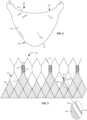
- FIG. 2 illustrates one of several leaflets 208 that form a valve assembly.
- Leaflet 208 extends between proximal end 202 and distal end 204 and includes a belly 230 having a free edge 210 stretching between attachment regions 212, which couple the leaflet to the commissure features of a stent.
- a substantially parabolic belly contour 214 is formed between attachment regions 212 on the edge of leaflet 208 opposite free edge 210.
- two leaflets 208 may be attached to each commissure feature of a stent.
- leaflets 208 of the valve assembly open and close, certain regions of one leaflet will repeatedly contact a similar region on the other leaflets, and may repeatedly contact hardened calcium nodules or a feature of the heart valve due to valve distortion from the hardened calcium. When this occurs, abrasion may occur at said region of the leaflet or at a corresponding region of the cuff.
- FIG. 3 illustrates heart valve 300, which includes stent 302 formed of struts 303 and an attached cuff 306. For the sake of clarity, leaflets are not shown.
- Stent 302 may include one or more annular rows of cells 312 connected to one another and a plurality of spaced commissure features 314 to which attachment features of the leaflet may be secured via eyelets 315.
- Cuff 306 is typically disposed on the luminal surface of annular stent 302 and includes three commissure peaks 307 for coupling with commissure features 314 of stent 302.
- cuff 306 may generally be formed of tissue, a polymer or a fabric. When formed of a fabric, cuff 306 may be cut from a large sheet into the shape shown in FIG. 3 . The cut edges 320 of the cuff 306 may be jagged and abrasive, as shown in the detailed view of the cuff edge.
- portions of leaflet 208 may contact the abrasive edges 320 of cuff 306, such as the edges 320 located adjacent struts 303a and 303b that define a midpeak 324 of cuff 306 located between commissure feature commissure peaks 307.
- abrasive edges 320 of cuff 306 such as the edges 320 located adjacent struts 303a and 303b that define a midpeak 324 of cuff 306 located between commissure feature commissure peaks 307.
- FIG. 4 illustrates heart valve 400, not falling under the scope of the claims, which includes stent 402 formed of struts 403 are attached fabric cuff 406.
- Stent 402 may include one or more annular rows of cells 412 connected to one another and a plurality of spaced commissure features 414 to which attachment features of the leaflet may be secured via eyelets 415.
- cuff 406 is disposed on the abluminal surface of stent 402 (e.g., as viewed from outside of the heart valve, cuff 406 overlies stent 402).
- struts (such as strut 403b) are positioned between the cuff 406 and the leaflets so that abrasion from the cut edges 420 of the cuff is minimized when the leaflets open. Additionally, cuff 406 may provide better sealing by being disposed on the abluminal surface.
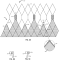
- FIG. 5A is an embodiment of a heart valve 500 in accordance with the invention, configured to minimize abrasion of the leaflets.
- Heart valve 500 is similar to heart valve 300 and includes stent 502 formed of struts 503 and an attached fabric cuff 506.
- Stent 502 may include one or more annular rows of cells 512 connected to one another and a plurality of spaced commissure features 514 to which attachment features of the leaflet may be secured via eyelets 515.
- cuff 506 is almost entirely disposed on the luminal surface of stent 502 with certain exceptions.
- Triangular midpeaks 524 of cuff 506 are disposed on the abluminal surface of stent 502 by passing portions of the cuff from the luminal surface to the abluminal surface through cell 512T. Specifically, each midpeak 524 of cuff 506 is attached to struts 503a and 503b on the abluminal surface of stent 502, and is attached to struts 503c and 503d on the luminal surface of the stent. In this manner, cut edges 520 of fabric cuff 506 may be disposed away from the moving leaflets. Additionally, cut edges 520 disposed on the abluminal surface may be folded prior to attachment to struts 503. In a first variation ( FIG.
- cut edge 520b of cuff 506b is folded toward strut 503 and hidden between cuff 506b and strut 503.
- cut edge 520c of cuff 506c may be folded away from strut 503. Regardless of whether cut edges 520 are folded and in which orientation, they may be secured to stent 502 with suture S as shown in the detailed view of FIG. 5A . With edges 520 hidden from the leaflets, the leaflets may open and close with little to no abrasion of the free edges.
- heart valve 600 includes stent 602 formed of struts 603 and an attached cuff 606.
- Stent 602 includes one or more annular rows of cells 612 connected to one another and a plurality of spaced commissure features 614 to which attachment features of the leaflet may be secured.
- cuff 606 is disposed on the luminal surface of stent 602. Unlike the previously described cuffs, cuff 606 includes two materials, a first material for forming main body 640 and a second material for forming the midpeaks. The second material forms discrete substantially triangular buffers 650 attached to main body 640.
- the first material of main body 640 may be a fabric to reduce the crimp profile of the heart valve.
- buffers 650 may be formed of a smooth second material, such as tissue or a polymer to minimize abrasion to the leaflets.
- midpeaks 624 may be removed from main body 640 along a cut edge 620, and each buffer 650 may be attached to cut edge 620 and to struts 603a, 603b using sutures as shown.
- about 2 to 3 mm of buffers 650 may overlap with main body 640 and leaflets may be sutured through twin layers of buffers 650 and main body 640. As the leaflets (not shown) open and close, the free edges of the leaflets contact buffer 650, which provides a smoother contact region.
- heart valve 700 includes stent 702 formed of struts 703 and an attached cuff 706.
- Stent 702 includes one or more annular rows of cells 712 connected to one another and a plurality of spaced commissure features 714 to which attachment features of the leaflet may be secured.
- a fabric cuff is desired to reduce the crimp profile of the heart valve. Because of the abrasion potential of fabric, other materials may be used to reduce abrasion to the leaflets.
- cuff 706 includes alternating fabric portions 706a and tissue portions 706b.
- Tissue portions 706b are disposed at midpeaks 724 between commissure features 714, while fabric portions 706a are disposed elsewhere including in the regions below commissure features 714. In this manner, the crimp profile is reduced through fabric portions 706a while abrasion is reduced via tissue portions 706b.
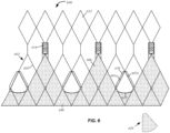
- FIG. 8 relates to an embodiment according to the invention and illustrates heart valve 800 including stent 802 having struts 803, an attached cuff 806, rows of cells 812 and commissure features 814.
- heart valve 800 may often be implanted in a less than ideal native valve annulus.
- the native valve annulus may be unevenly calcified or may have a cross-section that it not substantially circular (e.g., the valve annulus may be elliptical).
- the leaflets (not shown) may open and contact struts that are higher than cuff 806.
- longitudinal buffer strips 850 may be secured to select ones of struts 803.
- Buffer strips 850 may be formed of tissue, such as bovine or porcine pericardial tissue, or a polymer, such as ultra-high molecular weight polyethylene, polyurethane, polyester or suitable combinations thereof, and may be secured to the struts using sutures, glue, bioadhesive or other suitable techniques.
- Each buffer strip 850 extends along the length of a strut 803 and is wrapped around the strut. In FIG. 8 , each buffer strip 850 is secured to certain struts, such as struts 803a,803b located above a midpeak 824 of cuff 806. Strips 850 may be disposed in three groupings, each grouping forming a V-shaped cushion 852. It will be understood that, while FIG.
- buffer strips 850 may be coupled to other struts 803 and may form any number of suitable groupings.
- a full row of cells 812 may include buffer strips 850 along the top struts of the cells, the bottom struts of the cells or all four struts of one or more cells.
- FIG. 9A illustrates one such variation in which heart valve 900 includes stent 902 having struts 903, an attached cuff 906, rows of cells 912 and commissure features 914.
- buffer strips 950 may be secured to select struts.
- buffer strips 950a-d are wrapped around struts 903a-d to form a W-shaped cushion 952, the center of each cushion 952 being formed adjacent a midpeak 924 of cuff 906.
- One W-shaped cushion 952 is disposed between each pair of commissure features 914, though it will be understood that the cushions alternatively may be formed of strips 950 disposed in various groupings and/or orientations, such as the V-shaped orientations described in connection with FIG. 8 , or combinations of both the V-shaped and W-shaped cushions, or cushions formed in other shapes.
- FIGS. 9B and 9C illustrate two methods of attaching buffer strips 950 to strut 903.
- cuff 906B is wrapped around strut 903.
- Buffer strip 950B is disposed over cuff 906B and wrapped over a portion of strut 903 so as to be positioned on the luminal surface of stent 902.
- a suture S9 is then wrapped with a whip-stitch around strip 950B, cuff 906B and strut 903 to secure all three together.
- cuff 906C is doubled over itself to create a second layer 908C.
- Both layers overlie strut 903 on the luminal side of stent 902.
- a flat buffer strip 950C is then disposed over cuff 906C and a suture S10 pierces through buffer strip 950C and the two layers of cuff 906C to secure buffer strip 950C and cuff 906C to strut 903 using a whip-stitch pattern.
- any of the embodiments of the prosthetic heart valve described above may be used to replace a native heart valve, such as the aortic valve.
- the prosthetic heart valve may be delivered to the desired site in a patient (e.g., near a native aortic annulus) in a collapsed condition using any suitable delivery device.
- the delivery device may be introduced into the patient using a transfemoral, transapical, transseptal, transradial, transaortic, transsubclavian or other percutaneous approach.
- the user may deploy the prosthetic heart valve.
- the prosthetic heart valve expands into secure engagement within the native valve annulus.
- the prosthetic heart valve When the prosthetic heart valve has been properly positioned inside the heart, it works as a one-way valve, allowing blood to flow in one direction and preventing blood from flowing in the opposite direction. Any of the variations shown above, such as, for example, the buffer strips, may be helpful in reducing contact between the leaflets and struts of the heart valve when opening and closing, thereby reducing the potential for of abrasion of the leaflets.
- a prosthetic heart valve may include both buffer strips for reducing abrasion to the leaflets from the struts and an abluminal cuff to reduce abrasion to the leaflets from the cuff.
Description
- The present invention relates to heart valve replacement and, in particular, to collapsible prosthetic heart valves. More particularly, the present invention relates to collapsible prosthetic heart valves having leaflet abrasion mitigation features.
- Prosthetic heart valves that are collapsible to a relatively small circumferential size can be delivered into a patient less invasively than valves that are not collapsible. For example, a collapsible valve may be delivered into a patient via a tube-like delivery apparatus such as a catheter, a trocar, a laparoscopic instrument, or the like. This collapsibility can avoid the need for a more invasive procedure such as full open-chest, open-heart surgery.
- Collapsible prosthetic heart valves typically take the form of a valve structure mounted on a stent. There are two common types of stents on which the valve structures are ordinarily mounted: a self-expanding stent and a balloon-expandable stent. To place such valves into a delivery apparatus and ultimately into a patient, the valve may first be collapsed or crimped to reduce its circumferential size and diameter.
- When a collapsed prosthetic valve has reached the desired implant site in the patient (e.g., at or near the annulus of the patient's heart valve that is to be replaced by the prosthetic valve), the prosthetic valve can be deployed or released from the delivery apparatus and re-expanded to full operating use size. For balloon-expandable valves, this generally involves releasing the entire valve, assuring its proper location, and then expanding a balloon positioned within the valve stent. For self-expanding valves, on the other hand, the stent automatically expands as the sheath covering the valve is withdrawn.
-
US20130018458 is directed to embodiments of catheter-based prosthetic heart valves, and in particular, prosthetic heart valves having sealing devices configured to seal the interface between the prosthetic valve and the surrounding tissue of the native annulus in which the prosthetic valve is implanted. In one embodiment, a prosthetic heart valve includes an annular sealing member that can be placed in a delivery orientation extending axially away from one end of the valve when the valve is in a radially compressed state. When the valve is expanded, the expansion of the frame causes the sealing member to be pulled to an operative orientation covering a portion of the frame. -
US20110264206 provides prosthetic valves having sealing members on the external surface thereof. The prosthetic heart valves delivered by catheter directly through the apex of the heart or by other close range transcatheter delivery methods. Because these methods of implantation require a shorter length of catheter, a prosthetic valve can be more accurately oriented in the desired implantation location. Fluoroscopy can be used to further assist in orientation of the valve. The sealing members can be positioned on the prosthetic valve such that, when the prosthetic valve is implanted in a native annulus, each provided sealing member is located adjacent to a commissural point of the native valve leaflets. Because the sealing members are precisely oriented on the prosthetic valve, a physician can ensure that the sealing members are aligned with the commissural points of the native valve leaflets. The prosthetic valve can have a waisted middle section, and the sealing members can be located in the waisted middle section such that the crimped diameter of the prosthetic valve is not negatively impacted by the sealing members. -
US8632586 a method of replacing a deficient native aortic valve with a self-expandable prosthetic valve. The method involves advancing a self-expandable prosthetic valve through a tapered tube for crimping the prosthetic valve into a crimped diameter. The prosthetic valve is then advanced into a restriction tube for maintaining the prosthetic valve in the crimped diameter. The prosthetic valve is then advanced into a body and is positioned within the deficient native aortic valve. The prosthetic valve is then released from the restriction tube such that the prosthetic valve self-expands to an expanded diameter for anchoring within the deficient native aortic valve. The prosthetic valve comprises an expandable tubular support frame and a valve assembly positioned within the support frame. The valve assembly is formed with pericardial tissue and has three leaflets for providing blockage to a reverse flow of blood. -
US20090157175 an implantable prosthetic valve which has an upper frame section and a lower frame section. The upper frame section has a plurality of struts and a first leaflet receiving surface at a lower portion of the upper frame section. The lower frame section has a second leaflet receiving surface at an upper portion of the lower frame section. An edge of a flexible leaflet is disposed between the first and second leaflet receiving surfaces to attach the leaflet to the upper and lower frame sections. -
US201000082094 - The invention relates to prosthetic heart valves and is defined by
independent claims 1, 4, 12. According to the invention, the prosthetic heart valve includes a stent extending in a longitudinal direction, the stent being formed of a plurality of struts and having a plurality of commissure features, a collapsed condition and an expanded condition. A valve assembly may be secured to the stent, the valve assembly including a cuff and a plurality of leaflets, each of the leaflets having a free edge and being capable of alternating between an open position and a closed position. At least one buffer strip may be coupled to at least one of the plurality of struts and configured and arranged to minimize abrasion of the free edge of the leaflet in the open position. - According to the invention, the prosthetic heart valve includes a stent extending in a longitudinal direction, the stent being formed of a plurality of struts forming cells and having a plurality of commissure features, a collapsed condition and an expanded condition. A valve assembly may be secured to the stent, the valve assembly including a fabric cuff and a plurality of leaflets, at least a portion of the cuff being disposed on an abluminal surface of the stent, each of the leaflets having a free edge and being arranged to open such that the free edge is adjacent the portion of the cuff disposed on the abluminal surface of the stent.
- According to the invention, the prosthetic heart valve includes a stent extending in a longitudinal direction, the stent being formed of a plurality of struts forming cells and having a plurality of commissure features, a collapsed condition and an expanded condition. A valve assembly may be secured to the stent, the valve assembly including a cuff and a plurality of leaflets, the cuff being formed of a fabric and a second material different from the fabric, the cuff having commissure peaks and a plurality of midpeaks disposed between the commissure peaks, each of the leaflets having a free edge.
- Various embodiments of the present invention are described herein with reference to the drawings, wherein:
-
FIG. 1A is a partial side view of a prosthetic heart valve showing a potential strain distribution profile in the valve assembly; -
FIG. 1B is an enlarged partial view of the prosthetic heart valve ofFIG. 1A showing the strain distribution in the leaflet; -
FIG. 2 is a side view of a leaflet showing regions prone to abrasion; -
FIG. 3 is a highly schematic partial side view of a cuff disposed on the luminal surface of a stent; -
FIG. 4 is a highly schematic partial side view of a cuff entirely disposed on the abluminal surface of a stent; -
FIG. 5A is a highly schematic partial side view of a cuff having a cross-over region for passing from the luminal surface to the abluminal surface of a stent; -
FIGS. 5B and 5C are highly schematic cross-sections showing two variations of the folding of cut edges; -
FIG. 6 is a highly schematic partial side view of a cuff disposed on the luminal surface of a stent, the cuff having buffers; -
FIG. 7 is a highly schematic partial side view of a cuff disposed on the luminal surface of a stent, the cuff having alternating materials; -
FIG. 8 is a highly schematic partial side view of a cuff disposed on the luminal surface of a stent, the cuff having buffer strips; -
FIG. 9A is a highly schematic partial side view of another example of a cuff disposed on the luminal surface of a stent and having buffer strips; and -
FIGS. 9B and 9C are highly schematic cross-sections showing two variations of the attachment of buffer strips to a strut. - Various embodiments of the present invention will now be described with reference to the appended drawings. It will be appreciated that these drawings depict only some embodiments of the invention and are therefore not to be considered limiting of its scope.
- As used herein, the term "proximal," when used in connection with a prosthetic heart valve, refers to the end of the heart valve closest to the heart when the heart valve is implanted in a patient, whereas the term "distal," when used in connection with a prosthetic heart valve, refers to the end of the heart valve farthest from the heart when the heart valve is implanted in a patient. Also, as used herein, the words "substantially," "generally" and "about" are intended to mean that slight variations from absolute are included within the scope of the structure or process recited.
-
FIG. 1A shows a typical collapsibleprosthetic heart valve 100. Theprosthetic heart valve 100 is designed to replace the function of the native aortic valve of a patient. Examples of collapsible prosthetic heart valves are described in International Patent Application Publication No.WO/2009/042196 ;United States Patent No. 7,018,406 ; andUnited States Patent No. 7,329,278 ,. Although the invention is described herein as applied to a prosthetic heart valve for replacing a native aortic valve, the invention is not so limited, and may be applied to prosthetic valves for replacing other types of cardiac valves. - The
prosthetic heart valve 100 includes a stent orframe 102, which may be wholly or partly formed of any biocompatible material, such as metals, synthetic polymers, or biopolymers capable of functioning as a stent.Stent 102 is expandable and collapsible so thatprosthetic heart valve 100 may be transitioned between a collapsed condition and an expanded condition. Suitable biopolymers include, but are not limited to, elastin, and mixtures or composites thereof. Suitable metals include, but are not limited to, cobalt, titanium, nickel, chromium, stainless steel, and alloys thereof, including nitinol. Suitable synthetic polymers for use as a stent include, but are not limited to, thermoplastics, such as polyolefins, polyesters, polyamides, polysulfones, acrylics, polyacrylonitriles, polyetheretherketone (PEEK), and polyaramides. Thestent 102 may have anannulus section 110, an aortic section (not shown), and an intermediate section (not shown) disposed between the annulus and aortic sections. Each of theannulus section 110, the intermediate section, and the aortic section of thestent 102 includes a plurality ofcells 112 connected to one another around the stent. Theannulus section 110, the intermediate section, and the aortic section of thestent 102 may each include one or more annular rows ofcells 112 connected to one another. For instance, theannulus section 110 may have two annular rows ofcells 112. When theprosthetic heart valve 100 is in the expanded condition, eachcell 112 may be substantially diamond shaped. Regardless of its shape, eachcell 112 is formed by a plurality ofstruts 114. For example, acell 112 may be formed by fourstruts 114. - The
stent 102 includes commissure features or commissure posts (not shown) which may connect at least twocells 112 in the longitudinal direction of thestent 102. The commissure features may include eyelets that facilitate the suturing of a valve assembly and/or leaflets to thestent 102. - The
prosthetic heart valve 100 also includes avalve assembly 104 attached within theannulus section 110 of thestent 102.United States Patent Application Publication No. 2008/0228264 andUnited States Patent Application Publication No. 2008/0147179 describe suitable valve assemblies. Thevalve assembly 104 may be wholly or partly formed of any suitable biological material, fabric or a polymer. Examples of biological materials suitable for thevalve assembly 104 include, but are not limited to, porcine or bovine pericardial tissue. Examples of polymers suitable for thevalve assembly 104 include, but are not limited to, polyurethane and polyester. - The
valve assembly 104 may include acuff 106 disposed on the luminal surface ofannulus section 110, on the abluminal surface of the annulus section, or on both surfaces, and the cuff may cover all or part of either or both of the luminal and abluminal surfaces of the annulus section.FIG. 1A showscuff 106 disposed on the luminal surface ofannulus section 110 so as to cover part of the annulus section while leaving another part thereof uncovered. In addition to the materials for formingvalve assembly 104 noted above, thecuff 106 and/or any of the sutures described herein may include ultra-high-molecular-weight polyethylene. Thevalve assembly 104 may further include a plurality ofleaflets 108 which collectively function as a one-way valve. - The
cuff 106 of theprosthetic heart valve 100 ofFIG. 1A tends to experience relatively high strain and/or stress at certain locations. Insuch heart valves 100, the pressure of the blood thatleaflets 108 keep from flowing back into the left ventricle may subjectleaflets 108 to a load in the direction indicated by arrow L, shown inFIG. 1B . This load may cause high stress and/or strain on the cuff and/or leaflets, particularly where they are joined to one another. Moreover, a typical load may cause the cuff and/or leaflets to wear over time. To manage the increased stress and strain on thecuff 106, some conventional prosthetic heart valves have made the cuff thicker. However, thicker cuffs generally lead to a larger heart valve in the collapsed condition that is more difficult to deliver and implant. Instead of forming a thicker cuff, a different material such as fabric may be used. -
FIG. 2 illustrates one ofseveral leaflets 208 that form a valve assembly.Leaflet 208 extends betweenproximal end 202 anddistal end 204 and includes abelly 230 having afree edge 210 stretching betweenattachment regions 212, which couple the leaflet to the commissure features of a stent. A substantiallyparabolic belly contour 214 is formed betweenattachment regions 212 on the edge ofleaflet 208 oppositefree edge 210. In some examples, twoleaflets 208 may be attached to each commissure feature of a stent. When the valve assembly is functioning properly,free edges 210 ofleaflets 208 separate from one another to an open position to permit blood flow through the valve in one direction and coapt with one another in a closed position to impede blood flow in the opposite direction. In addition to the previously described strains, asleaflets 208 of the valve assembly open and close, certain regions of one leaflet will repeatedly contact a similar region on the other leaflets, and may repeatedly contact hardened calcium nodules or a feature of the heart valve due to valve distortion from the hardened calcium. When this occurs, abrasion may occur at said region of the leaflet or at a corresponding region of the cuff. -
FIG. 3 illustratesheart valve 300, which includesstent 302 formed ofstruts 303 and an attachedcuff 306. For the sake of clarity, leaflets are not shown.Stent 302 may include one or more annular rows ofcells 312 connected to one another and a plurality of spaced commissure features 314 to which attachment features of the leaflet may be secured viaeyelets 315. -
Cuff 306 is typically disposed on the luminal surface ofannular stent 302 and includes threecommissure peaks 307 for coupling with commissure features 314 ofstent 302. As discussed above,cuff 306 may generally be formed of tissue, a polymer or a fabric. When formed of a fabric,cuff 306 may be cut from a large sheet into the shape shown inFIG. 3 . The cut edges 320 of thecuff 306 may be jagged and abrasive, as shown in the detailed view of the cuff edge. As the leaflets repeatedly open and close, portions ofleaflet 208 may contact theabrasive edges 320 ofcuff 306, such as theedges 320 locatedadjacent struts midpeak 324 ofcuff 306 located between commissure feature commissure peaks 307. To minimize abrasion and provide safe contact between the cuff and leaflets, several improvements to the cuff design are proposed, as described below. -
FIG. 4 illustratesheart valve 400, not falling under the scope of the claims, which includesstent 402 formed ofstruts 403 are attachedfabric cuff 406. For the sake of clarity, leaflets are not shown.Stent 402 may include one or more annular rows ofcells 412 connected to one another and a plurality of spaced commissure features 414 to which attachment features of the leaflet may be secured viaeyelets 415. In this first example,cuff 406 is disposed on the abluminal surface of stent 402 (e.g., as viewed from outside of the heart valve,cuff 406 overlies stent 402). By positioningfabric cuff 406 on the abluminal surface of the stent, struts (such asstrut 403b) are positioned between thecuff 406 and the leaflets so that abrasion from the cut edges 420 of the cuff is minimized when the leaflets open. Additionally,cuff 406 may provide better sealing by being disposed on the abluminal surface. -
FIG. 5A is an embodiment of aheart valve 500 in accordance with the invention, configured to minimize abrasion of the leaflets.Heart valve 500 is similar toheart valve 300 and includesstent 502 formed ofstruts 503 and an attachedfabric cuff 506. For the sake of clarity, leaflets are not shown.Stent 502 may include one or more annular rows ofcells 512 connected to one another and a plurality of spaced commissure features 514 to which attachment features of the leaflet may be secured viaeyelets 515. In this example,cuff 506 is almost entirely disposed on the luminal surface ofstent 502 with certain exceptions.Triangular midpeaks 524 ofcuff 506 are disposed on the abluminal surface ofstent 502 by passing portions of the cuff from the luminal surface to the abluminal surface through cell 512T. Specifically, eachmidpeak 524 ofcuff 506 is attached tostruts stent 502, and is attached to struts 503c and 503d on the luminal surface of the stent. In this manner, cutedges 520 offabric cuff 506 may be disposed away from the moving leaflets. Additionally, cutedges 520 disposed on the abluminal surface may be folded prior to attachment to struts 503. In a first variation (FIG. 5B ), cutedge 520b of cuff 506b is folded towardstrut 503 and hidden between cuff 506b andstrut 503. In a second variation (FIG. 5C ), cutedge 520c ofcuff 506c may be folded away fromstrut 503. Regardless of whether cut edges 520 are folded and in which orientation, they may be secured tostent 502 with suture S as shown in the detailed view ofFIG. 5A . Withedges 520 hidden from the leaflets, the leaflets may open and close with little to no abrasion of the free edges. - In another embodiment according to the invention, shown in
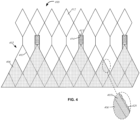
FIG. 6 ,heart valve 600 includesstent 602 formed ofstruts 603 and an attachedcuff 606.Stent 602 includes one or more annular rows of cells 612 connected to one another and a plurality of spaced commissure features 614 to which attachment features of the leaflet may be secured. In this example,cuff 606 is disposed on the luminal surface ofstent 602. Unlike the previously described cuffs,cuff 606 includes two materials, a first material for formingmain body 640 and a second material for forming the midpeaks. The second material forms discrete substantiallytriangular buffers 650 attached tomain body 640. - The first material of
main body 640 may be a fabric to reduce the crimp profile of the heart valve. In such cases,buffers 650 may be formed of a smooth second material, such as tissue or a polymer to minimize abrasion to the leaflets. As shown,midpeaks 624 may be removed frommain body 640 along acut edge 620, and eachbuffer 650 may be attached to cutedge 620 and tostruts buffers 650 may overlap withmain body 640 and leaflets may be sutured through twin layers ofbuffers 650 andmain body 640. As the leaflets (not shown) open and close, the free edges of theleaflets contact buffer 650, which provides a smoother contact region. - In
FIG. 7 , relating to an embodiment not falling under the scope of the claims,heart valve 700 includesstent 702 formed ofstruts 703 and an attachedcuff 706.Stent 702 includes one or more annular rows ofcells 712 connected to one another and a plurality of spaced commissure features 714 to which attachment features of the leaflet may be secured. In some cases, a fabric cuff is desired to reduce the crimp profile of the heart valve. Because of the abrasion potential of fabric, other materials may be used to reduce abrasion to the leaflets. For example,cuff 706 includes alternatingfabric portions 706a andtissue portions 706b.Tissue portions 706b are disposed atmidpeaks 724 between commissure features 714, whilefabric portions 706a are disposed elsewhere including in the regions below commissure features 714. In this manner, the crimp profile is reduced throughfabric portions 706a while abrasion is reduced viatissue portions 706b. -
FIG. 8 relates to an embodiment according to the invention and illustratesheart valve 800 includingstent 802 havingstruts 803, an attachedcuff 806, rows ofcells 812 and commissure features 814. It will be appreciated thatheart valve 800 may often be implanted in a less than ideal native valve annulus. For example, the native valve annulus may be unevenly calcified or may have a cross-section that it not substantially circular (e.g., the valve annulus may be elliptical). Under such circumstances, the leaflets (not shown) may open and contact struts that are higher thancuff 806. In order to minimize abrasion of the leaflets by the struts, longitudinal buffer strips 850 may be secured to select ones ofstruts 803. - Buffer strips 850 may be formed of tissue, such as bovine or porcine pericardial tissue, or a polymer, such as ultra-high molecular weight polyethylene, polyurethane, polyester or suitable combinations thereof, and may be secured to the struts using sutures, glue, bioadhesive or other suitable techniques. Each
buffer strip 850 extends along the length of astrut 803 and is wrapped around the strut. InFIG. 8 , eachbuffer strip 850 is secured to certain struts, such asstruts 803a,803b located above amidpeak 824 ofcuff 806.Strips 850 may be disposed in three groupings, each grouping forming a V-shapedcushion 852. It will be understood that, whileFIG. 8 illustrates V-shapedcushions 852 located directly abovemidpeaks 824, the positioning of buffer strips is not so limited and buffer strips 850 may be coupled toother struts 803 and may form any number of suitable groupings. For example, a full row ofcells 812 may include buffer strips 850 along the top struts of the cells, the bottom struts of the cells or all four struts of one or more cells. -
FIG. 9A illustrates one such variation in whichheart valve 900 includesstent 902 havingstruts 903, an attachedcuff 906, rows ofcells 912 and commissure features 914. In order to minimize abrasion of the leaflets bystruts 903, buffer strips 950 may be secured to select struts. In this variation,buffer strips 950a-d are wrapped around struts 903a-d to form a W-shapedcushion 952, the center of eachcushion 952 being formed adjacent amidpeak 924 ofcuff 906. One W-shapedcushion 952 is disposed between each pair of commissure features 914, though it will be understood that the cushions alternatively may be formed ofstrips 950 disposed in various groupings and/or orientations, such as the V-shaped orientations described in connection withFIG. 8 , or combinations of both the V-shaped and W-shaped cushions, or cushions formed in other shapes. - As previously discussed, strips 950 may be secured to selected struts using a variety of methods.
FIGS. 9B and 9C illustrate two methods of attachingbuffer strips 950 to strut 903. InFIG. 9B ,cuff 906B is wrapped aroundstrut 903. Buffer strip 950B is disposed overcuff 906B and wrapped over a portion ofstrut 903 so as to be positioned on the luminal surface ofstent 902. A suture S9 is then wrapped with a whip-stitch around strip 950B,cuff 906B and strut 903 to secure all three together. In an alternative example, shown inFIG. 9C ,cuff 906C is doubled over itself to create asecond layer 908C. Both layers overliestrut 903 on the luminal side ofstent 902. Aflat buffer strip 950C is then disposed overcuff 906C and a suture S10 pierces throughbuffer strip 950C and the two layers ofcuff 906C to securebuffer strip 950C andcuff 906C to strut 903 using a whip-stitch pattern. - In operation, any of the embodiments of the prosthetic heart valve described above may be used to replace a native heart valve, such as the aortic valve. The prosthetic heart valve may be delivered to the desired site in a patient (e.g., near a native aortic annulus) in a collapsed condition using any suitable delivery device. The delivery device may be introduced into the patient using a transfemoral, transapical, transseptal, transradial, transaortic, transsubclavian or other percutaneous approach. Once the delivery device has reached the target site, the user may deploy the prosthetic heart valve. Upon deployment, the prosthetic heart valve expands into secure engagement within the native valve annulus. When the prosthetic heart valve has been properly positioned inside the heart, it works as a one-way valve, allowing blood to flow in one direction and preventing blood from flowing in the opposite direction. Any of the variations shown above, such as, for example, the buffer strips, may be helpful in reducing contact between the leaflets and struts of the heart valve when opening and closing, thereby reducing the potential for of abrasion of the leaflets.
- Although the invention herein has been described with reference to particular embodiments, it is to be understood that these embodiments are merely illustrative of the principles and applications of the present invention. For example, a prosthetic heart valve may include both buffer strips for reducing abrasion to the leaflets from the struts and an abluminal cuff to reduce abrasion to the leaflets from the cuff. Thus any combination of the preceding features may be used together and it is therefore to be understood that numerous modifications may be made to the illustrative embodiments and that other arrangements may be devised without departing from the scope of the present invention as defined by the appended claims.
Claims (14)
- A prosthetic heart valve (600), comprising:a stent (602) extending in a longitudinal direction, the stent (602) being formed of a plurality of struts (603) forming cells (612) and having a plurality of commissure features (614), a collapsed condition and an expanded condition;a valve assembly secured to the stent, the valve assembly including a cuff (606) and a plurality of leaflets, the cuff being formed of a fabric and a second material different from the fabric, the cuff having commissure peaks and a plurality of midpeaks disposed between the commissure peaks, each of the leaflets having a free edge;characterised in that the cuff includes a plurality of triangular buffers (650) formed from the second material, each of the triangular buffers (650) including three edges and being disposed at one of the midpeaks, one of the edges (620) being coupled to the fabric, and two of the edges being coupled to struts (603a, 603b)such that abrasion between one of the leaflets and the cuff is minimised.
- The prosthetic heart valve according to claim 1, wherein the second material includes tissue.
- The prosthetic heart valve according to claim 1, wherein the second material includes a polymer.
- A prosthetic heart valve (800), comprising:a stent (802) extending in a longitudinal direction, the stent (802) being formed of a plurality of struts (803) and having a plurality of commissure features (814), a collapsed condition and an expanded condition;a valve assembly secured to the stent, the valve assembly including a cuff and a plurality of leaflets, each of the leaflets having a free edge and being capable of alternating between an open position and a closed position; andat least one buffer strip (850) coupled to at least one of the plurality of struts (803) and configured and arranged to minimize abrasion of the free edge of the leaflet in the open position;characterised in that the at least one buffer strip (850) includes two buffer strips arranged in a V-shaped cushion.
- The prosthetic heart valve according to claim 4, wherein the at least one buffer strip (850) is formed of tissue or a polymer.
- The prosthetic heart valve according to claim 4, wherein the at least one buffer strip (850) includes three groupings of buffer strips.
- The prosthetic heart valve according to claim 4, wherein the at least one buffer strip (850) includes multiple groupings of buffer strips.
- The prosthetic heart valve according to claim 4, wherein the at least one buffer strip (950) includes four buffer strips (950a, 950b, 950c, 950d) arranged in a W-shaped cushion (952).
- The prosthetic heart valve according to claim 8, wherein the cuff includes a plurality of midpeaks (924) disposed between an adjacent pair of the commissure features and the W-shaped cushions are centered about each of the plurality of midpeaks.
- The prosthetic heart valve according to claim 4, further comprising a suture (5) configured to wrap around one of the plurality of struts and the at least one buffer strip.
- The prosthetic heart valve according to claim 4, further comprising a suture (5) configured to pierce the cuff and the at least one buffer strip and to wrap around at least one of the plurality of struts.
- A prosthetic heart valve (500), comprising:a stent (502) extending in a longitudinal direction, the stent being formed of a plurality of struts forming cells and having a plurality of commissure features, a collapsed condition and an expanded condition;a valve assembly secured to the stent (502), the valve assembly including a fabric cuff (506) and a plurality of leaflets, at least a portion of the cuff being disposed on an abluminal surface of the stent, each of the leaflets having a free edge and being arranged to open such that the free edge is adjacent the portion of the cuff disposed on the abluminal surface of the stent;characterised in that the cuff (506) includes midpeak portions (524) and a remaining portion, the midpeak portions (524) being disposed on the abluminal surface of the stent and the remaining portion being disposed on a luminal surface of the stent.
- The prosthetic heart valve according to claim 12, wherein the midpeak portions (524) pass through select cells (512T) of the stent from the luminal surface of the stent to the abluminal surface of the stent.
- The prosthetic heart valve according to claim 13, wherein at least one edge (520) of each of the midpeak portions is folded.
Applications Claiming Priority (2)
| Application Number | Priority Date | Filing Date | Title |
|---|---|---|---|
| US201461979072P | 2014-04-14 | 2014-04-14 | |
| PCT/US2015/025499 WO2015160675A1 (en) | 2014-04-14 | 2015-04-13 | Leaflet abrasion mitigation in prosthetic heart valves |
Publications (2)
| Publication Number | Publication Date |
|---|---|
| EP3131504A1 EP3131504A1 (en) | 2017-02-22 |
| EP3131504B1 true EP3131504B1 (en) | 2023-03-15 |
Family
ID=53005704
Family Applications (1)
| Application Number | Title | Priority Date | Filing Date |
|---|---|---|---|
| EP15718727.9A Active EP3131504B1 (en) | 2014-04-14 | 2015-04-13 | Leaflet abrasion mitigation in prosthetic heart valves |
Country Status (3)
| Country | Link |
|---|---|
| US (3) | US10226332B2 (en) |
| EP (1) | EP3131504B1 (en) |
| WO (1) | WO2015160675A1 (en) |
Families Citing this family (10)
| Publication number | Priority date | Publication date | Assignee | Title |
|---|---|---|---|---|
| US9675451B2 (en) * | 2013-02-01 | 2017-06-13 | Medtronic CV Luxembourg S.a.r.l. | Anti-paravalvular leakage component for a transcatheter valve prosthesis |
| US10653523B2 (en) | 2017-01-19 | 2020-05-19 | 4C Medical Technologies, Inc. | Systems, methods and devices for delivery systems, methods and devices for implanting prosthetic heart valves |
| US10561495B2 (en) | 2017-01-24 | 2020-02-18 | 4C Medical Technologies, Inc. | Systems, methods and devices for two-step delivery and implantation of prosthetic heart valve |
| BR112020007850A2 (en) | 2017-10-19 | 2020-12-01 | Admedus Corporation | heart valve replacement device with reduced suture |
| US11857441B2 (en) | 2018-09-04 | 2024-01-02 | 4C Medical Technologies, Inc. | Stent loading device |
| GB2577052B (en) * | 2018-09-11 | 2021-04-28 | Strait Access Tech Holdings Pty Ltd | Expandable sleeved stent and method of making such stent |
| EP3923864A1 (en) * | 2019-02-13 | 2021-12-22 | Edwards Lifesciences Corporation | Heart valve frame design with non-uniform struts |
| US11931253B2 (en) | 2020-01-31 | 2024-03-19 | 4C Medical Technologies, Inc. | Prosthetic heart valve delivery system: ball-slide attachment |
| US20230248513A1 (en) | 2020-07-07 | 2023-08-10 | Anteris Technologies Corporation | Expandable frame for improved hemodynamic performance of transcatheter replacement heart valve |
| US11622853B1 (en) | 2022-09-30 | 2023-04-11 | Anteris Technologies Corporation | Prosthetic heart valves |
Citations (15)
| Publication number | Priority date | Publication date | Assignee | Title |
|---|---|---|---|---|
| US20100036484A1 (en) | 2008-06-06 | 2010-02-11 | Edwards Lifesciences Corporation | Low profile transcatheter heart valve |
| US20100168839A1 (en) | 2007-06-04 | 2010-07-01 | Braido Peter N | Prosthetic heart valves |
| US20100204781A1 (en) | 2007-08-24 | 2010-08-12 | Alkhatib Yousef F | Prosthetic aortic heart valves |
| WO2010098857A1 (en) | 2009-02-27 | 2010-09-02 | St. Jude Medical, Inc. | Stent features for collapsible prosthetic heart valves |
| US20110295363A1 (en) | 2010-05-25 | 2011-12-01 | Girard Michael J | Prosthetic Heart Valve And Transcatheter Delivered Endoprosthesis Comprising A Prosthetic Heart Valve And A Stent |
| US20120071969A1 (en) | 2010-09-20 | 2012-03-22 | St. Jude Medical, Cardiology Division, Inc.d/b/a St. Jude Medical, Cardiovascular Division | Valve leaflet attachment in collapsible prosthetic valves |
| US20120078357A1 (en) | 2010-09-27 | 2012-03-29 | Edwards Lifesciences Corporation | Prosthetic Heart Valve Frame With Flexible Commissures |
| WO2012048035A2 (en) | 2010-10-05 | 2012-04-12 | Edwards Lifesciences Corporation | Prosthetic heart valve |
| US20140005776A1 (en) | 2012-06-29 | 2014-01-02 | St. Jude Medical, Cardiology Division, Inc. | Leaflet attachment for function in various shapes and sizes |
| US20140155997A1 (en) | 2007-09-28 | 2014-06-05 | Peter Nicholas Braido | Collapsible-expandable prosthetic heart valves with structures for clamping native tissue |
| WO2014158710A2 (en) | 2013-03-14 | 2014-10-02 | St. Jude Medical, Cardiology Division, Inc. | Cuff configurations for prosthetic heart valve |
| WO2015038458A1 (en) | 2013-09-12 | 2015-03-19 | St. Jude Medical, Cardiology Division, Inc. | Stent designs for prosthetic heart valves |
| WO2015094936A1 (en) | 2013-12-19 | 2015-06-25 | St. Jude Medical, Cardiology Division, Inc. | Leaflet-cuff attachments for prosthetic heart valve |
| EP2898859A1 (en) | 2014-01-24 | 2015-07-29 | St. Jude Medical, Cardiology Division, Inc. | Stationary intra-annular halo designs for paravalvular leak (PVL) reduction - active channel filling cuff designs |
| WO2015126711A1 (en) | 2014-02-18 | 2015-08-27 | St. Jude Medical, Cardiology Division, Inc. | Bowed runners and corresponding valve assemblies for paravalvular leak protection |
Family Cites Families (162)
| Publication number | Priority date | Publication date | Assignee | Title |
|---|---|---|---|---|
| US3657744A (en) | 1970-05-08 | 1972-04-25 | Univ Minnesota | Method for fixing prosthetic implants in a living body |
| US4491986A (en) | 1976-05-12 | 1985-01-08 | Shlomo Gabbay | Heart valve |
| US4759758A (en) | 1984-12-07 | 1988-07-26 | Shlomo Gabbay | Prosthetic heart valve |
| DE3640745A1 (en) | 1985-11-30 | 1987-06-04 | Ernst Peter Prof Dr M Strecker | Catheter for producing or extending connections to or between body cavities |
| US4878906A (en) | 1986-03-25 | 1989-11-07 | Servetus Partnership | Endoprosthesis for repairing a damaged vessel |
| US4994077A (en) | 1989-04-21 | 1991-02-19 | Dobben Richard L | Artificial heart valve for implantation in a blood vessel |
| DK124690D0 (en) | 1990-05-18 | 1990-05-18 | Henning Rud Andersen | FAT PROTECTION FOR IMPLEMENTATION IN THE BODY FOR REPLACEMENT OF NATURAL FLEET AND CATS FOR USE IN IMPLEMENTING A SUCH FAT PROTECTION |
| US5411552A (en) | 1990-05-18 | 1995-05-02 | Andersen; Henning R. | Valve prothesis for implantation in the body and a catheter for implanting such valve prothesis |
| ES2051664T3 (en) * | 1991-05-08 | 1997-04-01 | Nika Health Products Ltd | PROCEDURE AND APPARATUS FOR THE MANUFACTURE OF A HEART VALVE PROSTHESIS. |
| US5843167A (en) | 1993-04-22 | 1998-12-01 | C. R. Bard, Inc. | Method and apparatus for recapture of hooked endoprosthesis |
| US5480423A (en) | 1993-05-20 | 1996-01-02 | Boston Scientific Corporation | Prosthesis delivery |
| US5713950A (en) | 1993-11-01 | 1998-02-03 | Cox; James L. | Method of replacing heart valves using flexible tubes |
| DE69419877T2 (en) | 1993-11-04 | 1999-12-16 | Bard Inc C R | Fixed vascular prosthesis |
| GB9522332D0 (en) | 1995-11-01 | 1996-01-03 | Biocompatibles Ltd | Braided stent |
| ATE218052T1 (en) | 1995-11-27 | 2002-06-15 | Schneider Europ Gmbh | STENT FOR USE IN A PHYSICAL PASSAGE |
| US7238197B2 (en) | 2000-05-30 | 2007-07-03 | Devax, Inc. | Endoprosthesis deployment system for treating vascular bifurcations |
| US5855601A (en) | 1996-06-21 | 1999-01-05 | The Trustees Of Columbia University In The City Of New York | Artificial heart valve and method and device for implanting the same |
| EP0850607A1 (en) | 1996-12-31 | 1998-07-01 | Cordis Corporation | Valve prosthesis for implantation in body channels |
| CN1172636C (en) | 1997-01-24 | 2004-10-27 | 乔米德有限公司 | Bistable spring construction for a stent and other medical apparatus |
| US5961549A (en) | 1997-04-03 | 1999-10-05 | Baxter International Inc. | Multi-leaflet bioprosthetic heart valve |
| US5954766A (en) | 1997-09-16 | 1999-09-21 | Zadno-Azizi; Gholam-Reza | Body fluid flow control device |
| US5938697A (en) | 1998-03-04 | 1999-08-17 | Scimed Life Systems, Inc. | Stent having variable properties |
| US5935163A (en) | 1998-03-31 | 1999-08-10 | Shelhigh, Inc. | Natural tissue heart valve prosthesis |
| US7452371B2 (en) | 1999-06-02 | 2008-11-18 | Cook Incorporated | Implantable vascular device |
| US6254564B1 (en) | 1998-09-10 | 2001-07-03 | Percardia, Inc. | Left ventricular conduit with blood vessel graft |
| US6214036B1 (en) | 1998-11-09 | 2001-04-10 | Cordis Corporation | Stent which is easily recaptured and repositioned within the body |
| DE19857887B4 (en) | 1998-12-15 | 2005-05-04 | Fraunhofer-Gesellschaft zur Förderung der angewandten Forschung e.V. | Anchoring support for a heart valve prosthesis |
| US6558414B2 (en) | 1999-02-02 | 2003-05-06 | Impra, Inc. | Partial encapsulation of stents using strips and bands |
| US6090140A (en) | 1999-02-17 | 2000-07-18 | Shelhigh, Inc. | Extra-anatomic heart valve apparatus |
| US6264691B1 (en) | 1999-04-23 | 2001-07-24 | Shlomo Gabbay | Apparatus and method for supporting a heart valve |
| DE69942954D1 (en) | 1999-09-10 | 2010-12-30 | Cook Inc | ENDOVASCULAR TREATMENT OF CHRONIC VENOUS INSUFFICIENCY |
| US6440164B1 (en) | 1999-10-21 | 2002-08-27 | Scimed Life Systems, Inc. | Implantable prosthetic valve |
| US20070043435A1 (en) | 1999-11-17 | 2007-02-22 | Jacques Seguin | Non-cylindrical prosthetic valve system for transluminal delivery |
| US8579966B2 (en) | 1999-11-17 | 2013-11-12 | Medtronic Corevalve Llc | Prosthetic valve for transluminal delivery |
| US7018406B2 (en) | 1999-11-17 | 2006-03-28 | Corevalve Sa | Prosthetic valve for transluminal delivery |
| US8016877B2 (en) | 1999-11-17 | 2011-09-13 | Medtronic Corevalve Llc | Prosthetic valve for transluminal delivery |
| FR2800984B1 (en) | 1999-11-17 | 2001-12-14 | Jacques Seguin | DEVICE FOR REPLACING A HEART VALVE PERCUTANEOUSLY |
| FR2815844B1 (en) | 2000-10-31 | 2003-01-17 | Jacques Seguin | TUBULAR SUPPORT FOR THE PERCUTANEOUS POSITIONING OF A REPLACEMENT HEART VALVE |
| US6458153B1 (en) | 1999-12-31 | 2002-10-01 | Abps Venture One, Ltd. | Endoluminal cardiac and venous valve prostheses and methods of manufacture and delivery thereof |
| US7195641B2 (en) | 1999-11-19 | 2007-03-27 | Advanced Bio Prosthetic Surfaces, Ltd. | Valvular prostheses having metal or pseudometallic construction and methods of manufacture |
| MXPA02007426A (en) | 2000-01-31 | 2003-10-14 | Cook Biotech Inc | Stent valves and uses of same. |
| WO2001056500A2 (en) | 2000-02-03 | 2001-08-09 | Cook Incorporated | Implantable vascular device |
| US6454799B1 (en) | 2000-04-06 | 2002-09-24 | Edwards Lifesciences Corporation | Minimally-invasive heart valves and methods of use |
| US6610088B1 (en) | 2000-05-03 | 2003-08-26 | Shlomo Gabbay | Biologically covered heart valve prosthesis |
| US6368348B1 (en) | 2000-05-15 | 2002-04-09 | Shlomo Gabbay | Annuloplasty prosthesis for supporting an annulus of a heart valve |
| US6419695B1 (en) | 2000-05-22 | 2002-07-16 | Shlomo Gabbay | Cardiac prosthesis for helping improve operation of a heart valve |
| US6869444B2 (en) | 2000-05-22 | 2005-03-22 | Shlomo Gabbay | Low invasive implantable cardiac prosthesis and method for helping improve operation of a heart valve |
| US8366769B2 (en) * | 2000-06-01 | 2013-02-05 | Edwards Lifesciences Corporation | Low-profile, pivotable heart valve sewing ring |
| US7510572B2 (en) | 2000-09-12 | 2009-03-31 | Shlomo Gabbay | Implantation system for delivery of a heart valve prosthesis |
| WO2002022054A1 (en) | 2000-09-12 | 2002-03-21 | Gabbay S | Valvular prosthesis and method of using same |
| US20020036220A1 (en) | 2000-09-26 | 2002-03-28 | Shlomo Gabbay | Curved implantable sheath and method of making same |
| US6783556B1 (en) | 2000-09-26 | 2004-08-31 | Shlomo Gabbay | System and method for making a calotte-shaped implantable sheath |
| US6685625B2 (en) | 2000-09-26 | 2004-02-03 | Shlomo Gabbay | Curved implantable sheath and method of making same |
| US6517576B2 (en) | 2000-12-11 | 2003-02-11 | Shlomo Gabbay | Implantable patch prosthesis having one or more cusps for improved competency |
| ATE310470T1 (en) | 2000-12-15 | 2005-12-15 | Angiomed Ag | STENT WITH HEART VALVE |
| US6468660B2 (en) | 2000-12-29 | 2002-10-22 | St. Jude Medical, Inc. | Biocompatible adhesives |
| US6623518B2 (en) | 2001-02-26 | 2003-09-23 | Ev3 Peripheral, Inc. | Implant delivery system with interlock |
| US7556646B2 (en) | 2001-09-13 | 2009-07-07 | Edwards Lifesciences Corporation | Methods and apparatuses for deploying minimally-invasive heart valves |
| DE10121210B4 (en) | 2001-04-30 | 2005-11-17 | Universitätsklinikum Freiburg | Anchoring element for the intraluminal anchoring of a heart valve replacement and method for its production |
| FR2828091B1 (en) | 2001-07-31 | 2003-11-21 | Seguin Jacques | ASSEMBLY ALLOWING THE PLACEMENT OF A PROTHETIC VALVE IN A BODY DUCT |
| US20080021552A1 (en) | 2001-10-09 | 2008-01-24 | Shlomo Gabbay | Apparatus To Facilitate Implantation |
| US6893460B2 (en) | 2001-10-11 | 2005-05-17 | Percutaneous Valve Technologies Inc. | Implantable prosthetic valve |
| DE10221076A1 (en) | 2002-05-11 | 2003-11-27 | Ruesch Willy Gmbh | stent |
| US7137184B2 (en) | 2002-09-20 | 2006-11-21 | Edwards Lifesciences Corporation | Continuous heart valve support frame and method of manufacture |
| US6814746B2 (en) | 2002-11-01 | 2004-11-09 | Ev3 Peripheral, Inc. | Implant delivery system with marker interlock |
| FR2847800B1 (en) | 2002-11-28 | 2005-10-14 | Perouse Laboratoires | INTERCHANGEABLE PROTHETIC VALVE |
| FR2850008A1 (en) | 2003-01-17 | 2004-07-23 | Daniel Roux | Vascular prosthesis has tube and collar for adapting to blood vessel ends of different diameters |
| US7399315B2 (en) * | 2003-03-18 | 2008-07-15 | Edwards Lifescience Corporation | Minimally-invasive heart valve with cusp positioners |
| EP1605871B1 (en) | 2003-03-20 | 2008-07-23 | Aortech International PLC | Valve |
| WO2004096100A1 (en) | 2003-04-24 | 2004-11-11 | Cook Incorporated | Artificial valve prosthesis with improved flow dynamics |
| US7717952B2 (en) | 2003-04-24 | 2010-05-18 | Cook Incorporated | Artificial prostheses with preferred geometries |
| US7201772B2 (en) | 2003-07-08 | 2007-04-10 | Ventor Technologies, Ltd. | Fluid flow prosthetic device |
| US7160322B2 (en) | 2003-08-13 | 2007-01-09 | Shlomo Gabbay | Implantable cardiac prosthesis for mitigating prolapse of a heart valve |
| US20060259137A1 (en) | 2003-10-06 | 2006-11-16 | Jason Artof | Minimally invasive valve replacement system |
| US8182528B2 (en) | 2003-12-23 | 2012-05-22 | Sadra Medical, Inc. | Locking heart valve anchor |
| US8343213B2 (en) | 2003-12-23 | 2013-01-01 | Sadra Medical, Inc. | Leaflet engagement elements and methods for use thereof |
| US20050137686A1 (en) | 2003-12-23 | 2005-06-23 | Sadra Medical, A Delaware Corporation | Externally expandable heart valve anchor and method |
| US8052749B2 (en) | 2003-12-23 | 2011-11-08 | Sadra Medical, Inc. | Methods and apparatus for endovascular heart valve replacement comprising tissue grasping elements |
| US9005273B2 (en) | 2003-12-23 | 2015-04-14 | Sadra Medical, Inc. | Assessing the location and performance of replacement heart valves |
| US7871435B2 (en) * | 2004-01-23 | 2011-01-18 | Edwards Lifesciences Corporation | Anatomically approximate prosthetic mitral heart valve |
| US7311730B2 (en) | 2004-02-13 | 2007-12-25 | Shlomo Gabbay | Support apparatus and heart valve prosthesis for sutureless implantation |
| US7247167B2 (en) | 2004-02-19 | 2007-07-24 | Shlomo Gabbay | Low profile heart valve prosthesis |
| ITTO20040135A1 (en) | 2004-03-03 | 2004-06-03 | Sorin Biomedica Cardio Spa | CARDIAC VALVE PROSTHESIS |
| EP1734903B2 (en) | 2004-03-11 | 2022-01-19 | Percutaneous Cardiovascular Solutions Pty Limited | Percutaneous heart valve prosthesis |
| US20050256566A1 (en) | 2004-05-03 | 2005-11-17 | Shlomo Gabbay | Apparatus and method for improving ventricular function |
| US7374573B2 (en) | 2004-05-03 | 2008-05-20 | Shlomo Gabbay | System and method for improving ventricular function |
| WO2005107650A2 (en) * | 2004-05-05 | 2005-11-17 | Direct Flow Medical, Inc. | Unstented heart valve with formed in place support structure |
| US20060122692A1 (en) | 2004-05-10 | 2006-06-08 | Ran Gilad | Stent valve and method of using same |
| US20060008497A1 (en) | 2004-07-09 | 2006-01-12 | Shlomo Gabbay | Implantable apparatus having improved biocompatibility and process of making the same |
| FR2874812B1 (en) | 2004-09-07 | 2007-06-15 | Perouse Soc Par Actions Simpli | INTERCHANGEABLE PROTHETIC VALVE |
| CA2583591C (en) | 2004-10-02 | 2018-10-30 | Christoph Hans Huber | Methods and devices for repair or replacement of heart valves or adjacent tissue without the need for full cardiopulmonary support |
| US8562672B2 (en) | 2004-11-19 | 2013-10-22 | Medtronic, Inc. | Apparatus for treatment of cardiac valves and method of its manufacture |
| EP1848368A1 (en) | 2004-12-20 | 2007-10-31 | Cook Incorporated | Intraluminal support frame and medical devices including the support frame |
| DE602005022491D1 (en) | 2005-01-05 | 2010-09-02 | Cleveland Clinic Foundation | PROCESS FOR FIXING TISSUE |
| ITTO20050074A1 (en) | 2005-02-10 | 2006-08-11 | Sorin Biomedica Cardio Srl | CARDIAC VALVE PROSTHESIS |
| SE531468C2 (en) | 2005-04-21 | 2009-04-14 | Edwards Lifesciences Ag | An apparatus for controlling blood flow |
| US8597276B2 (en) | 2005-05-12 | 2013-12-03 | Covidien Lp | Implant delivery system with interlocked RX port orientation |
| US7914569B2 (en) | 2005-05-13 | 2011-03-29 | Medtronics Corevalve Llc | Heart valve prosthesis and methods of manufacture and use |
| US7799072B2 (en) | 2005-05-20 | 2010-09-21 | The Cleveland Clinic Foundation | Apparatus and methods for repairing the function of a diseased valve and method for making same |
| US20090112309A1 (en) | 2005-07-21 | 2009-04-30 | The Florida International University Board Of Trustees | Collapsible Heart Valve with Polymer Leaflets |
| WO2007016097A2 (en) | 2005-07-27 | 2007-02-08 | Georgia Tech Research Corporation | Implantable prosthetic vascular valve |
| US8790396B2 (en) | 2005-07-27 | 2014-07-29 | Medtronic 3F Therapeutics, Inc. | Methods and systems for cardiac valve delivery |
| US20070055358A1 (en) | 2005-08-22 | 2007-03-08 | Krolik Jeffrey A | Axially compressible flared stents and apparatus and methods for delivering them |
| US20070067029A1 (en) | 2005-09-16 | 2007-03-22 | Shlomo Gabbay | Support apparatus to facilitate implantation of cardiac prosthesis |
| US8092525B2 (en) | 2005-10-26 | 2012-01-10 | Cardiosolutions, Inc. | Heart valve implant |
| EP1948088A2 (en) | 2005-11-18 | 2008-07-30 | Innovia LLC | Trileaflet heart valve |
| MX2008008068A (en) | 2005-12-22 | 2008-09-10 | Symetis Sa | Stent-valves for valve replacement and associated methods and systems for surgery. |
| US20070213813A1 (en) | 2005-12-22 | 2007-09-13 | Symetis Sa | Stent-valves for valve replacement and associated methods and systems for surgery |
| EP2004095B1 (en) | 2006-03-28 | 2019-06-12 | Medtronic, Inc. | Prosthetic cardiac valve formed from pericardium material and methods of making same |
| US7524331B2 (en) | 2006-04-06 | 2009-04-28 | Medtronic Vascular, Inc. | Catheter delivered valve having a barrier to provide an enhanced seal |
| US20070244545A1 (en) | 2006-04-14 | 2007-10-18 | Medtronic Vascular, Inc. | Prosthetic Conduit With Radiopaque Symmetry Indicators |
| EP2023860A2 (en) * | 2006-04-29 | 2009-02-18 | Arbor Surgical Technologies, Inc. | Multiple component prosthetic heart valve assemblies and apparatus and methods for delivering them |
| EP2478872B1 (en) | 2006-05-30 | 2018-07-04 | Cook Medical Technologies LLC | Artificial valve prosthesis |
| US20080097595A1 (en) | 2006-08-22 | 2008-04-24 | Shlomo Gabbay | Intraventricular cardiac prosthesis |
| US8052750B2 (en) | 2006-09-19 | 2011-11-08 | Medtronic Ventor Technologies Ltd | Valve prosthesis fixation techniques using sandwiching |
| US7534261B2 (en) | 2006-10-02 | 2009-05-19 | Edwards Lifesciences Corporation | Sutureless heart valve attachment |
| US8747459B2 (en) | 2006-12-06 | 2014-06-10 | Medtronic Corevalve Llc | System and method for transapical delivery of an annulus anchored self-expanding valve |
| FR2909857B1 (en) | 2006-12-14 | 2009-03-06 | Perouse Soc Par Actions Simpli | Endovalve. |
| US8353954B2 (en) | 2006-12-19 | 2013-01-15 | St. Jude Medical, Inc. | Prosthetic heart valve including stent structure and tissue leaflets, and related methods |
| US8236045B2 (en) | 2006-12-22 | 2012-08-07 | Edwards Lifesciences Corporation | Implantable prosthetic valve assembly and method of making the same |
| WO2008101193A2 (en) | 2007-02-16 | 2008-08-21 | Emory University | Apparatus and methods for treating the aorta |
| US8092523B2 (en) | 2007-03-12 | 2012-01-10 | St. Jude Medical, Inc. | Prosthetic heart valves with flexible leaflets |
| AU2008262426B2 (en) | 2007-06-08 | 2014-10-23 | St. Jude Medical, Inc. | Devices for transcatheter prosthetic heart valve implantation and access closure |
| ES2375426T3 (en) | 2007-06-26 | 2012-02-29 | St. Jude Medical, Inc. | APPLIANCE FOR THE IMPLEMENTATION OF REPLIGABLE / EXPANSIBLE PROTESTIC HEART VALVES. |
| EP2572675B1 (en) | 2007-09-26 | 2016-06-22 | St. Jude Medical, Inc. | Collapsible prosthetic heart valves |
| WO2009045334A1 (en) | 2007-09-28 | 2009-04-09 | St. Jude Medical, Inc. | Collapsible/expandable prosthetic heart valves with native calcified leaflet retention features |
| WO2009045331A1 (en) | 2007-09-28 | 2009-04-09 | St. Jude Medical, Inc. | Two-stage collapsible/expandable prosthetic heart valves and anchoring systems |
| US20090138079A1 (en) | 2007-10-10 | 2009-05-28 | Vector Technologies Ltd. | Prosthetic heart valve for transfemoral delivery |
| EP2205184B2 (en) | 2007-11-05 | 2023-01-11 | St. Jude Medical, LLC | Collapsible/expandable prosthetic heart valves with non-expanding stent posts and retrieval features |
| US20080114452A1 (en) | 2007-11-14 | 2008-05-15 | Shlomo Gabbay | Prosthesis exhibiting post-implantation size change |
| PT2628464T (en) * | 2007-12-14 | 2020-03-05 | Edwards Lifesciences Corp | Prosthetic valve |
| EP2240121B1 (en) | 2008-01-16 | 2019-05-22 | St. Jude Medical, Inc. | Delivery and retrieval systems for collapsible/expandable prosthetic heart valves |
| JP2011512948A (en) | 2008-02-25 | 2011-04-28 | メドトロニック カルディオ ヴァスキュラー インコーポレイテッド | Funnel reduction tool |
| DE202009018961U1 (en) | 2008-07-15 | 2014-11-26 | St. Jude Medical, Inc. | Heart valve prosthesis and arrangement for delivering a heart valve prosthesis |
| US9226820B2 (en) | 2008-07-15 | 2016-01-05 | St. Jude Medical, Inc. | Axially anchoring collapsible and re-expandable prosthetic heart valves for various disease states |
| DE202008009610U1 (en) | 2008-07-17 | 2008-12-11 | Nvt Ag | Prosthetic heart valve system |
| EP2901966B1 (en) * | 2008-09-29 | 2016-06-29 | Edwards Lifesciences CardiAQ LLC | Heart valve |
| ES2644852T3 (en) | 2009-02-20 | 2017-11-30 | St. Jude Medical, Inc. | Devices and methods for folding prosthetic heart valves |
| US20100217382A1 (en) | 2009-02-25 | 2010-08-26 | Edwards Lifesciences | Mitral valve replacement with atrial anchoring |
| EP2810620B1 (en) | 2009-04-15 | 2022-09-14 | Edwards Lifesciences CardiAQ LLC | Vascular implant and delivery system |
| US8845722B2 (en) | 2009-08-03 | 2014-09-30 | Shlomo Gabbay | Heart valve prosthesis and method of implantation thereof |
| DK2560580T3 (en) | 2010-04-21 | 2019-08-12 | Medtronic Inc | PROTEST CLAP WITH SEALING ELEMENTS |
| USD652926S1 (en) | 2010-09-20 | 2012-01-24 | St. Jude Medical, Inc. | Forked end |
| USD652927S1 (en) | 2010-09-20 | 2012-01-24 | St. Jude Medical, Inc. | Surgical stent |
| USD653342S1 (en) | 2010-09-20 | 2012-01-31 | St. Jude Medical, Inc. | Stent connections |
| USD654169S1 (en) | 2010-09-20 | 2012-02-14 | St. Jude Medical Inc. | Forked ends |
| USD654170S1 (en) | 2010-09-20 | 2012-02-14 | St. Jude Medical, Inc. | Stent connections |
| USD653341S1 (en) | 2010-09-20 | 2012-01-31 | St. Jude Medical, Inc. | Surgical stent |
| USD660967S1 (en) | 2010-09-20 | 2012-05-29 | St. Jude Medical, Inc. | Surgical stent |
| USD648854S1 (en) | 2010-09-20 | 2011-11-15 | St. Jude Medical, Inc. | Commissure points |
| USD660432S1 (en) | 2010-09-20 | 2012-05-22 | St. Jude Medical, Inc. | Commissure point |
| USD660433S1 (en) | 2010-09-20 | 2012-05-22 | St. Jude Medical, Inc. | Surgical stent assembly |
| USD653343S1 (en) | 2010-09-20 | 2012-01-31 | St. Jude Medical, Inc. | Surgical cuff |
| US8795357B2 (en) * | 2011-07-15 | 2014-08-05 | Edwards Lifesciences Corporation | Perivalvular sealing for transcatheter heart valve |
| WO2013086413A1 (en) * | 2011-12-09 | 2013-06-13 | Edwards Lifesciences Corporation | Prosthetic heart valve improved commissure supports |
| US9554902B2 (en) * | 2012-06-28 | 2017-01-31 | St. Jude Medical, Cardiology Division, Inc. | Leaflet in configuration for function in various shapes and sizes |
| US9289292B2 (en) * | 2012-06-28 | 2016-03-22 | St. Jude Medical, Cardiology Division, Inc. | Valve cuff support |
| US9913715B2 (en) * | 2013-11-06 | 2018-03-13 | St. Jude Medical, Cardiology Division, Inc. | Paravalvular leak sealing mechanism |
| US10583003B2 (en) * | 2014-05-06 | 2020-03-10 | Dsm Ip Assets B.V. | Method of making a prosthetic valve and valve obtained therewith |
| US10195025B2 (en) * | 2014-05-12 | 2019-02-05 | Edwards Lifesciences Corporation | Prosthetic heart valve |
| US10232564B2 (en) * | 2015-04-29 | 2019-03-19 | Edwards Lifesciences Corporation | Laminated sealing member for prosthetic heart valve |
| US9974650B2 (en) * | 2015-07-14 | 2018-05-22 | Edwards Lifesciences Corporation | Prosthetic heart valve |
-
2015
- 2015-04-13 WO PCT/US2015/025499 patent/WO2015160675A1/en active Application Filing
- 2015-04-13 EP EP15718727.9A patent/EP3131504B1/en active Active
- 2015-04-13 US US14/684,589 patent/US10226332B2/en active Active
-
2019
- 2019-01-22 US US16/254,000 patent/US11147666B2/en active Active
-
2021
- 2021-09-28 US US17/487,376 patent/US20220008197A1/en active Pending
Patent Citations (15)
| Publication number | Priority date | Publication date | Assignee | Title |
|---|---|---|---|---|
| US20100168839A1 (en) | 2007-06-04 | 2010-07-01 | Braido Peter N | Prosthetic heart valves |
| US20100204781A1 (en) | 2007-08-24 | 2010-08-12 | Alkhatib Yousef F | Prosthetic aortic heart valves |
| US20140155997A1 (en) | 2007-09-28 | 2014-06-05 | Peter Nicholas Braido | Collapsible-expandable prosthetic heart valves with structures for clamping native tissue |
| US20100036484A1 (en) | 2008-06-06 | 2010-02-11 | Edwards Lifesciences Corporation | Low profile transcatheter heart valve |
| WO2010098857A1 (en) | 2009-02-27 | 2010-09-02 | St. Jude Medical, Inc. | Stent features for collapsible prosthetic heart valves |
| US20110295363A1 (en) | 2010-05-25 | 2011-12-01 | Girard Michael J | Prosthetic Heart Valve And Transcatheter Delivered Endoprosthesis Comprising A Prosthetic Heart Valve And A Stent |
| US20120071969A1 (en) | 2010-09-20 | 2012-03-22 | St. Jude Medical, Cardiology Division, Inc.d/b/a St. Jude Medical, Cardiovascular Division | Valve leaflet attachment in collapsible prosthetic valves |
| US20120078357A1 (en) | 2010-09-27 | 2012-03-29 | Edwards Lifesciences Corporation | Prosthetic Heart Valve Frame With Flexible Commissures |
| WO2012048035A2 (en) | 2010-10-05 | 2012-04-12 | Edwards Lifesciences Corporation | Prosthetic heart valve |
| US20140005776A1 (en) | 2012-06-29 | 2014-01-02 | St. Jude Medical, Cardiology Division, Inc. | Leaflet attachment for function in various shapes and sizes |
| WO2014158710A2 (en) | 2013-03-14 | 2014-10-02 | St. Jude Medical, Cardiology Division, Inc. | Cuff configurations for prosthetic heart valve |
| WO2015038458A1 (en) | 2013-09-12 | 2015-03-19 | St. Jude Medical, Cardiology Division, Inc. | Stent designs for prosthetic heart valves |
| WO2015094936A1 (en) | 2013-12-19 | 2015-06-25 | St. Jude Medical, Cardiology Division, Inc. | Leaflet-cuff attachments for prosthetic heart valve |
| EP2898859A1 (en) | 2014-01-24 | 2015-07-29 | St. Jude Medical, Cardiology Division, Inc. | Stationary intra-annular halo designs for paravalvular leak (PVL) reduction - active channel filling cuff designs |
| WO2015126711A1 (en) | 2014-02-18 | 2015-08-27 | St. Jude Medical, Cardiology Division, Inc. | Bowed runners and corresponding valve assemblies for paravalvular leak protection |
Also Published As
| Publication number | Publication date |
|---|---|
| US11147666B2 (en) | 2021-10-19 |
| WO2015160675A1 (en) | 2015-10-22 |
| EP3131504A1 (en) | 2017-02-22 |
| US20190151082A1 (en) | 2019-05-23 |
| US20220008197A1 (en) | 2022-01-13 |
| US10226332B2 (en) | 2019-03-12 |
| US20150289973A1 (en) | 2015-10-15 |
Similar Documents
| Publication | Publication Date | Title |
|---|---|---|
| EP3131504B1 (en) | Leaflet abrasion mitigation in prosthetic heart valves | |
| US11413142B2 (en) | Stent assembly for use in prosthetic heart valves | |
| US11660186B2 (en) | Valve assembly for crimp profile | |
| US10321990B2 (en) | Leaflet abrasion mitigation | |
| US10512539B2 (en) | Prosthetic heart valve system and delivery system therefor | |
| US8932343B2 (en) | Blunt ended stent for prosthetic heart valve | |
| EP2129333B1 (en) | Replacement prosthetic heart valves | |
| US10390948B2 (en) | Leaflet-cuff attachments for prosthetic heart valve | |
| WO2015175450A1 (en) | Transcatheter valve with paravalvular leak sealing ring | |
| EP3668455B1 (en) | Heart valve frame design with non-uniform struts | |
| US20230355381A1 (en) | Detachable Cell Configuration for Valve in Valve | |
| US20220387175A1 (en) | Prosthetic heart valve |
Legal Events
| Date | Code | Title | Description |
|---|---|---|---|
| STAA | Information on the status of an ep patent application or granted ep patent |
Free format text: STATUS: THE INTERNATIONAL PUBLICATION HAS BEEN MADE |
|
| PUAI | Public reference made under article 153(3) epc to a published international application that has entered the european phase |
Free format text: ORIGINAL CODE: 0009012 |
|
| STAA | Information on the status of an ep patent application or granted ep patent |
Free format text: STATUS: REQUEST FOR EXAMINATION WAS MADE |
|
| 17P | Request for examination filed |
Effective date: 20160927 |
|
| AK | Designated contracting states |
Kind code of ref document: A1 Designated state(s): AL AT BE BG CH CY CZ DE DK EE ES FI FR GB GR HR HU IE IS IT LI LT LU LV MC MK MT NL NO PL PT RO RS SE SI SK SM TR |
|
| AX | Request for extension of the european patent |
Extension state: BA ME |
|
| DAV | Request for validation of the european patent (deleted) | ||
| DAX | Request for extension of the european patent (deleted) | ||
| STAA | Information on the status of an ep patent application or granted ep patent |
Free format text: STATUS: EXAMINATION IS IN PROGRESS |
|
| 17Q | First examination report despatched |
Effective date: 20190403 |
|
| STAA | Information on the status of an ep patent application or granted ep patent |
Free format text: STATUS: EXAMINATION IS IN PROGRESS |
|
| GRAP | Despatch of communication of intention to grant a patent |
Free format text: ORIGINAL CODE: EPIDOSNIGR1 |
|
| STAA | Information on the status of an ep patent application or granted ep patent |
Free format text: STATUS: GRANT OF PATENT IS INTENDED |
|
| INTG | Intention to grant announced |
Effective date: 20221006 |
|
| GRAS | Grant fee paid |
Free format text: ORIGINAL CODE: EPIDOSNIGR3 |
|
| GRAA | (expected) grant |
Free format text: ORIGINAL CODE: 0009210 |
|
| STAA | Information on the status of an ep patent application or granted ep patent |
Free format text: STATUS: THE PATENT HAS BEEN GRANTED |
|
| AK | Designated contracting states |
Kind code of ref document: B1 Designated state(s): AL AT BE BG CH CY CZ DE DK EE ES FI FR GB GR HR HU IE IS IT LI LT LU LV MC MK MT NL NO PL PT RO RS SE SI SK SM TR |
|
| REG | Reference to a national code |
Ref country code: CH Ref legal event code: EP Ref country code: GB Ref legal event code: FG4D |
|
| REG | Reference to a national code |
Ref country code: DE Ref legal event code: R096 Ref document number: 602015082795 Country of ref document: DE |
|
| REG | Reference to a national code |
Ref country code: IE Ref legal event code: FG4D |
|
| REG | Reference to a national code |
Ref country code: AT Ref legal event code: REF Ref document number: 1553556 Country of ref document: AT Kind code of ref document: T Effective date: 20230415 |
|
| REG | Reference to a national code |
Ref country code: LT Ref legal event code: MG9D |
|
| REG | Reference to a national code |
Ref country code: NL Ref legal event code: MP Effective date: 20230315 |
|
| P01 | Opt-out of the competence of the unified patent court (upc) registered |
Effective date: 20230616 |
|
| PG25 | Lapsed in a contracting state [announced via postgrant information from national office to epo] |
Ref country code: RS Free format text: LAPSE BECAUSE OF FAILURE TO SUBMIT A TRANSLATION OF THE DESCRIPTION OR TO PAY THE FEE WITHIN THE PRESCRIBED TIME-LIMIT Effective date: 20230315 Ref country code: NO Free format text: LAPSE BECAUSE OF FAILURE TO SUBMIT A TRANSLATION OF THE DESCRIPTION OR TO PAY THE FEE WITHIN THE PRESCRIBED TIME-LIMIT Effective date: 20230615 Ref country code: LV Free format text: LAPSE BECAUSE OF FAILURE TO SUBMIT A TRANSLATION OF THE DESCRIPTION OR TO PAY THE FEE WITHIN THE PRESCRIBED TIME-LIMIT Effective date: 20230315 Ref country code: LT Free format text: LAPSE BECAUSE OF FAILURE TO SUBMIT A TRANSLATION OF THE DESCRIPTION OR TO PAY THE FEE WITHIN THE PRESCRIBED TIME-LIMIT Effective date: 20230315 Ref country code: HR Free format text: LAPSE BECAUSE OF FAILURE TO SUBMIT A TRANSLATION OF THE DESCRIPTION OR TO PAY THE FEE WITHIN THE PRESCRIBED TIME-LIMIT Effective date: 20230315 |
|
| PGFP | Annual fee paid to national office [announced via postgrant information from national office to epo] |
Ref country code: DE Payment date: 20230327 Year of fee payment: 9 |
|
| REG | Reference to a national code |
Ref country code: AT Ref legal event code: MK05 Ref document number: 1553556 Country of ref document: AT Kind code of ref document: T Effective date: 20230315 |
|
| PG25 | Lapsed in a contracting state [announced via postgrant information from national office to epo] |
Ref country code: SE Free format text: LAPSE BECAUSE OF FAILURE TO SUBMIT A TRANSLATION OF THE DESCRIPTION OR TO PAY THE FEE WITHIN THE PRESCRIBED TIME-LIMIT Effective date: 20230315 Ref country code: NL Free format text: LAPSE BECAUSE OF FAILURE TO SUBMIT A TRANSLATION OF THE DESCRIPTION OR TO PAY THE FEE WITHIN THE PRESCRIBED TIME-LIMIT Effective date: 20230315 Ref country code: GR Free format text: LAPSE BECAUSE OF FAILURE TO SUBMIT A TRANSLATION OF THE DESCRIPTION OR TO PAY THE FEE WITHIN THE PRESCRIBED TIME-LIMIT Effective date: 20230616 Ref country code: FI Free format text: LAPSE BECAUSE OF FAILURE TO SUBMIT A TRANSLATION OF THE DESCRIPTION OR TO PAY THE FEE WITHIN THE PRESCRIBED TIME-LIMIT Effective date: 20230315 |
|
| PG25 | Lapsed in a contracting state [announced via postgrant information from national office to epo] |
Ref country code: SM Free format text: LAPSE BECAUSE OF FAILURE TO SUBMIT A TRANSLATION OF THE DESCRIPTION OR TO PAY THE FEE WITHIN THE PRESCRIBED TIME-LIMIT Effective date: 20230315 Ref country code: RO Free format text: LAPSE BECAUSE OF FAILURE TO SUBMIT A TRANSLATION OF THE DESCRIPTION OR TO PAY THE FEE WITHIN THE PRESCRIBED TIME-LIMIT Effective date: 20230315 Ref country code: PT Free format text: LAPSE BECAUSE OF FAILURE TO SUBMIT A TRANSLATION OF THE DESCRIPTION OR TO PAY THE FEE WITHIN THE PRESCRIBED TIME-LIMIT Effective date: 20230717 Ref country code: ES Free format text: LAPSE BECAUSE OF FAILURE TO SUBMIT A TRANSLATION OF THE DESCRIPTION OR TO PAY THE FEE WITHIN THE PRESCRIBED TIME-LIMIT Effective date: 20230315 Ref country code: EE Free format text: LAPSE BECAUSE OF FAILURE TO SUBMIT A TRANSLATION OF THE DESCRIPTION OR TO PAY THE FEE WITHIN THE PRESCRIBED TIME-LIMIT Effective date: 20230315 Ref country code: CZ Free format text: LAPSE BECAUSE OF FAILURE TO SUBMIT A TRANSLATION OF THE DESCRIPTION OR TO PAY THE FEE WITHIN THE PRESCRIBED TIME-LIMIT Effective date: 20230315 Ref country code: AT Free format text: LAPSE BECAUSE OF FAILURE TO SUBMIT A TRANSLATION OF THE DESCRIPTION OR TO PAY THE FEE WITHIN THE PRESCRIBED TIME-LIMIT Effective date: 20230315 |
|
| PGFP | Annual fee paid to national office [announced via postgrant information from national office to epo] |
Ref country code: GB Payment date: 20230412 Year of fee payment: 9 |
|
| PG25 | Lapsed in a contracting state [announced via postgrant information from national office to epo] |
Ref country code: SK Free format text: LAPSE BECAUSE OF FAILURE TO SUBMIT A TRANSLATION OF THE DESCRIPTION OR TO PAY THE FEE WITHIN THE PRESCRIBED TIME-LIMIT Effective date: 20230315 Ref country code: PL Free format text: LAPSE BECAUSE OF FAILURE TO SUBMIT A TRANSLATION OF THE DESCRIPTION OR TO PAY THE FEE WITHIN THE PRESCRIBED TIME-LIMIT Effective date: 20230315 Ref country code: IS Free format text: LAPSE BECAUSE OF FAILURE TO SUBMIT A TRANSLATION OF THE DESCRIPTION OR TO PAY THE FEE WITHIN THE PRESCRIBED TIME-LIMIT Effective date: 20230715 |
|
| REG | Reference to a national code |
Ref country code: CH Ref legal event code: PL |
|
| REG | Reference to a national code |
Ref country code: DE Ref legal event code: R026 Ref document number: 602015082795 Country of ref document: DE |
|
| PLBI | Opposition filed |
Free format text: ORIGINAL CODE: 0009260 |
|
| PG25 | Lapsed in a contracting state [announced via postgrant information from national office to epo] |
Ref country code: LU Free format text: LAPSE BECAUSE OF NON-PAYMENT OF DUE FEES Effective date: 20230413 |
|
| PLAX | Notice of opposition and request to file observation + time limit sent |
Free format text: ORIGINAL CODE: EPIDOSNOBS2 |
|
| REG | Reference to a national code |
Ref country code: BE Ref legal event code: MM Effective date: 20230430 |
|
| PG25 | Lapsed in a contracting state [announced via postgrant information from national office to epo] |
Ref country code: MC Free format text: LAPSE BECAUSE OF FAILURE TO SUBMIT A TRANSLATION OF THE DESCRIPTION OR TO PAY THE FEE WITHIN THE PRESCRIBED TIME-LIMIT Effective date: 20230315 |
|
| 26 | Opposition filed |
Opponent name: EIP LIMITED Effective date: 20231215 |
|
| PG25 | Lapsed in a contracting state [announced via postgrant information from national office to epo] |
Ref country code: SI Free format text: LAPSE BECAUSE OF FAILURE TO SUBMIT A TRANSLATION OF THE DESCRIPTION OR TO PAY THE FEE WITHIN THE PRESCRIBED TIME-LIMIT Effective date: 20230315 Ref country code: MC Free format text: LAPSE BECAUSE OF FAILURE TO SUBMIT A TRANSLATION OF THE DESCRIPTION OR TO PAY THE FEE WITHIN THE PRESCRIBED TIME-LIMIT Effective date: 20230315 Ref country code: LI Free format text: LAPSE BECAUSE OF NON-PAYMENT OF DUE FEES Effective date: 20230430 Ref country code: DK Free format text: LAPSE BECAUSE OF FAILURE TO SUBMIT A TRANSLATION OF THE DESCRIPTION OR TO PAY THE FEE WITHIN THE PRESCRIBED TIME-LIMIT Effective date: 20230315 Ref country code: CH Free format text: LAPSE BECAUSE OF NON-PAYMENT OF DUE FEES Effective date: 20230430 |
|
| REG | Reference to a national code |
Ref country code: IE Ref legal event code: MM4A |
|
| PG25 | Lapsed in a contracting state [announced via postgrant information from national office to epo] |
Ref country code: BE Free format text: LAPSE BECAUSE OF NON-PAYMENT OF DUE FEES Effective date: 20230430 |
|
| PG25 | Lapsed in a contracting state [announced via postgrant information from national office to epo] |
Ref country code: IE Free format text: LAPSE BECAUSE OF NON-PAYMENT OF DUE FEES Effective date: 20230413 |