EP3131192A1 - Control device and method for controlling a safety-relevant component - Google Patents
Control device and method for controlling a safety-relevant component Download PDFInfo
- Publication number
- EP3131192A1 EP3131192A1 EP15181147.8A EP15181147A EP3131192A1 EP 3131192 A1 EP3131192 A1 EP 3131192A1 EP 15181147 A EP15181147 A EP 15181147A EP 3131192 A1 EP3131192 A1 EP 3131192A1
- Authority
- EP
- European Patent Office
- Prior art keywords
- control device
- switching
- computers
- computer
- transformer
- Prior art date
- Legal status (The legal status is an assumption and is not a legal conclusion. Google has not performed a legal analysis and makes no representation as to the accuracy of the status listed.)
- Granted
Links
- 238000000034 method Methods 0.000 title claims description 6
- 230000001360 synchronised effect Effects 0.000 claims abstract description 5
- 238000012544 monitoring process Methods 0.000 claims description 19
- 238000013461 design Methods 0.000 claims description 5
- 238000001514 detection method Methods 0.000 claims description 2
- 238000002955 isolation Methods 0.000 claims description 2
- 238000012546 transfer Methods 0.000 description 4
- 230000005540 biological transmission Effects 0.000 description 3
- 238000012545 processing Methods 0.000 description 2
- XEEYBQQBJWHFJM-UHFFFAOYSA-N Iron Chemical group [Fe] XEEYBQQBJWHFJM-UHFFFAOYSA-N 0.000 description 1
- 101000879675 Streptomyces lavendulae Subtilisin inhibitor-like protein 4 Proteins 0.000 description 1
- 230000004888 barrier function Effects 0.000 description 1
- 238000010276 construction Methods 0.000 description 1
- 125000004122 cyclic group Chemical group 0.000 description 1
- 230000007547 defect Effects 0.000 description 1
- 230000002950 deficient Effects 0.000 description 1
- 238000011161 development Methods 0.000 description 1
- 238000005516 engineering process Methods 0.000 description 1
- 238000012423 maintenance Methods 0.000 description 1
- 239000000463 material Substances 0.000 description 1
- 230000000704 physical effect Effects 0.000 description 1
- 238000000926 separation method Methods 0.000 description 1
- 238000012360 testing method Methods 0.000 description 1
Images

Classifications
-
- H—ELECTRICITY
- H02—GENERATION; CONVERSION OR DISTRIBUTION OF ELECTRIC POWER
- H02M—APPARATUS FOR CONVERSION BETWEEN AC AND AC, BETWEEN AC AND DC, OR BETWEEN DC AND DC, AND FOR USE WITH MAINS OR SIMILAR POWER SUPPLY SYSTEMS; CONVERSION OF DC OR AC INPUT POWER INTO SURGE OUTPUT POWER; CONTROL OR REGULATION THEREOF
- H02M1/00—Details of apparatus for conversion
- H02M1/32—Means for protecting converters other than automatic disconnection
-
- B—PERFORMING OPERATIONS; TRANSPORTING
- B61—RAILWAYS
- B61L—GUIDING RAILWAY TRAFFIC; ENSURING THE SAFETY OF RAILWAY TRAFFIC
- B61L1/00—Devices along the route controlled by interaction with the vehicle or train
- B61L1/16—Devices for counting axles; Devices for counting vehicles
- B61L1/167—Circuit details
-
- B—PERFORMING OPERATIONS; TRANSPORTING
- B61—RAILWAYS
- B61L—GUIDING RAILWAY TRAFFIC; ENSURING THE SAFETY OF RAILWAY TRAFFIC
- B61L1/00—Devices along the route controlled by interaction with the vehicle or train
- B61L1/18—Railway track circuits
- B61L1/181—Details
-
- B—PERFORMING OPERATIONS; TRANSPORTING
- B61—RAILWAYS
- B61L—GUIDING RAILWAY TRAFFIC; ENSURING THE SAFETY OF RAILWAY TRAFFIC
- B61L29/00—Safety means for rail/road crossing traffic
- B61L29/24—Means for warning road traffic that a gate is closed or closing, or that rail traffic is approaching, e.g. for visible or audible warning
- B61L29/28—Means for warning road traffic that a gate is closed or closing, or that rail traffic is approaching, e.g. for visible or audible warning electrically operated
- B61L29/288—Wiring diagram of the signal control circuits
-
- B—PERFORMING OPERATIONS; TRANSPORTING
- B61—RAILWAYS
- B61L—GUIDING RAILWAY TRAFFIC; ENSURING THE SAFETY OF RAILWAY TRAFFIC
- B61L5/00—Local operating mechanisms for points or track-mounted scotch-blocks; Visible or audible signals; Local operating mechanisms for visible or audible signals
- B61L5/12—Visible signals
- B61L5/18—Light signals; Mechanisms associated therewith, e.g. blinders
- B61L5/1809—Daylight signals
- B61L5/1881—Wiring diagrams for power supply, control or testing
-
- B—PERFORMING OPERATIONS; TRANSPORTING
- B61—RAILWAYS
- B61L—GUIDING RAILWAY TRAFFIC; ENSURING THE SAFETY OF RAILWAY TRAFFIC
- B61L7/00—Remote control of local operating means for points, signals, or track-mounted scotch-blocks
- B61L7/06—Remote control of local operating means for points, signals, or track-mounted scotch-blocks using electrical transmission
- B61L7/08—Circuitry
-
- H—ELECTRICITY
- H02—GENERATION; CONVERSION OR DISTRIBUTION OF ELECTRIC POWER
- H02H—EMERGENCY PROTECTIVE CIRCUIT ARRANGEMENTS
- H02H7/00—Emergency protective circuit arrangements specially adapted for specific types of electric machines or apparatus or for sectionalised protection of cable or line systems, and effecting automatic switching in the event of an undesired change from normal working conditions
- H02H7/08—Emergency protective circuit arrangements specially adapted for specific types of electric machines or apparatus or for sectionalised protection of cable or line systems, and effecting automatic switching in the event of an undesired change from normal working conditions for dynamo-electric motors
- H02H7/0833—Emergency protective circuit arrangements specially adapted for specific types of electric machines or apparatus or for sectionalised protection of cable or line systems, and effecting automatic switching in the event of an undesired change from normal working conditions for dynamo-electric motors for electric motors with control arrangements
- H02H7/0844—Fail safe control, e.g. by comparing control signal and controlled current, isolating motor on commutation error
-
- H—ELECTRICITY
- H02—GENERATION; CONVERSION OR DISTRIBUTION OF ELECTRIC POWER
- H02M—APPARATUS FOR CONVERSION BETWEEN AC AND AC, BETWEEN AC AND DC, OR BETWEEN DC AND DC, AND FOR USE WITH MAINS OR SIMILAR POWER SUPPLY SYSTEMS; CONVERSION OF DC OR AC INPUT POWER INTO SURGE OUTPUT POWER; CONTROL OR REGULATION THEREOF
- H02M1/00—Details of apparatus for conversion
- H02M1/08—Circuits specially adapted for the generation of control voltages for semiconductor devices incorporated in static converters
- H02M1/084—Circuits specially adapted for the generation of control voltages for semiconductor devices incorporated in static converters using a control circuit common to several phases of a multi-phase system
-
- H—ELECTRICITY
- H02—GENERATION; CONVERSION OR DISTRIBUTION OF ELECTRIC POWER
- H02M—APPARATUS FOR CONVERSION BETWEEN AC AND AC, BETWEEN AC AND DC, OR BETWEEN DC AND DC, AND FOR USE WITH MAINS OR SIMILAR POWER SUPPLY SYSTEMS; CONVERSION OF DC OR AC INPUT POWER INTO SURGE OUTPUT POWER; CONTROL OR REGULATION THEREOF
- H02M3/00—Conversion of dc power input into dc power output
- H02M3/22—Conversion of dc power input into dc power output with intermediate conversion into ac
- H02M3/24—Conversion of dc power input into dc power output with intermediate conversion into ac by static converters
- H02M3/28—Conversion of dc power input into dc power output with intermediate conversion into ac by static converters using discharge tubes with control electrode or semiconductor devices with control electrode to produce the intermediate ac
- H02M3/325—Conversion of dc power input into dc power output with intermediate conversion into ac by static converters using discharge tubes with control electrode or semiconductor devices with control electrode to produce the intermediate ac using devices of a triode or a transistor type requiring continuous application of a control signal
- H02M3/335—Conversion of dc power input into dc power output with intermediate conversion into ac by static converters using discharge tubes with control electrode or semiconductor devices with control electrode to produce the intermediate ac using devices of a triode or a transistor type requiring continuous application of a control signal using semiconductor devices only
- H02M3/33569—Conversion of dc power input into dc power output with intermediate conversion into ac by static converters using discharge tubes with control electrode or semiconductor devices with control electrode to produce the intermediate ac using devices of a triode or a transistor type requiring continuous application of a control signal using semiconductor devices only having several active switching elements
- H02M3/33573—Full-bridge at primary side of an isolation transformer
Definitions
- the invention relates to a control device and a method for controlling a safety-relevant component.
- Out DE 3003291 C2 is a two-channel data processing arrangement with two same data processing microcontrollers known, each microcontroller controls a transformer.
- a clock signal converts a DC signal into an AC signal so that the signal can be transmitted through the first transformer.
- the second transformer can be switched by means of the second microcontroller.
- a data transfer takes place only if both microcontrollers give a switching signal to the respective transformer.
- a disadvantage of this arrangement is the high hardware requirements, in particular with regard to the transformers, which is associated with high costs, large space requirements and poor efficiency.
- axle counter (Az LM) from Thales Transportation Systems GmbH is known, which has a dual-channel control device with parallel relay interfaces.
- this device is susceptible to wear and vibration, whereby contacts of the relay can be solved.
- the control device comprises a transformer for outputting a control signal, an H-bridge circuit with two switching branches and a bridge branch, each switching branch comprising a switching element pair consisting of two series-connected switching elements and the bridge branch as load a primary coil of the transformer.
- the control device further comprises two independent, synchronized computers, each computer operating one of the switching element pairs by means of control elements, e.g. In the case of a switching command, the computers are arranged to alternately open and close the switching elements of each switching element pair at a predetermined frequency, so that the transformer is supplied with an alternating voltage of the predetermined frequency.
- the controls are controlled by the computers so that each time a switching element is opened in each switching element pair and a switching element is closed.
- the two computers are synchronized.
- further switching elements may be present in each switching branch, in particular in order to increase the availability (redundancy).
- Transformers have the indelible physical property that energy transfer occurs only when exposed to alternating current.
- the inventive control of the H-bridge (transistor bridge) generates an alternating voltage, whereby a control signal is output to the safety-relevant component to be controlled via the transformer.
- the transformer is jointly controlled by two computers (microcontrollers) independent of each other (in the sense of the standard DIN EN 50129 valid at the time of application), each computer controlling a voltage pole of the transformer. If one of the calculators no more switching command outputs, or one of the switch no longer switches, the current in the primary coil is no longer reversed and there is no energy transfer in the transformer more or the voltage output from the transformer drops to a very small value, causing a shutdown of the Current flow can be initiated by the control device. The control device thus makes itself ineffective and is thus transferred to a safe state. In this way, the SIL4 level required for railway safety components can be achieved.
- monitoring elements for monitoring the switching states of the switching elements are present.
- the monitoring elements detect a signal relating to the switching state of the respective switching element, which is transmitted to the associated computer (that is, the computer which is responsible for the control of the relevant switching element), so that it can be checked whether the switching element is working properly. This is generally done by comparing the switching state, which was determined on the basis of the transmitted signal, with a desired switching state, which is stored in the computer).
- a further development of this embodiment provides that the monitoring elements are each connected to both computers for transmitting a signal relating to the switching state of the respective switching element to both computers. This provides a way to synchronize the computers. The security can be further increased if one of the computer no longer issues switching commands as soon as it detects that the other computer no longer issues switching commands or no longer switch the switching elements assigned to it.
- the one of the computer controlled switching elements via lines, each with a resistor in safety design with the other computer connected are.
- the safety design guarantees that the resistance can only increase but not decrease in the event of a defect, so that a short circuit can be safely avoided.
- "Guaranteed” in this context means that the probability of a drag reduction is so extremely small that one considers this event to be excluded. This property of the device is considered captive as long as no overloading of the component occurs. The overload case must therefore be excluded by the circuit and dimensioning of the components.
- the monitoring elements are optocouplers, which are each connected in parallel to one of the switching elements.
- the switching elements can thereby be controlled electrically isolated from the corresponding computer.
- the two computers can be connected to each other via a data line.
- Information regarding the switching commands for switching the switching elements can thus be exchanged directly between the two computers (alternatively or additionally to the information transmission of the monitoring elements to both computers).
- the two computers are designed as a master-slave configuration.
- a galvanic separation between computers and switching elements can be realized, for example, that serve as controls optocouplers. Due to the inherent properties of the optocouplers computer and switching elements are galvanically separated from each other and data transmission can only be done in one direction. A manipulation of the data transmission direction in the microcontrollers by software can thus excluded. Alternatively, transformers can be used as controls.
- the transformer is followed by a rectifier.
- safety-related components can be operated with direct current.
- a "safe state” means a behavior of the technology which does not represent any danger to the operation (persons and material) and which is always attainable regardless of the error that has occurred.
- the invention is preferably used in the railway sector.
- the safety-relevant component can then be, for example, a signal lamp, a train detection system or a level crossing gate.
- the invention also relates to a method for controlling a safety-relevant component with a control device described above, wherein the computer of the control device in the case of an input switching command, the switching elements of each switching element pair alternately open and close in a predetermined frequency, so that the transformer with an AC voltage of predetermined frequency is supplied.
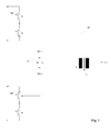
- Fig. 1 shows the basic configuration of the control device according to the invention.
- the control device comprises an H-bridge circuit with two switching branches SZ1, SZ2 and a bridge branch BZ.
- a switching element pair S1 / S2, S3 / S4 is arranged with two switching elements S1, S2, S3, S4 connected in series.
- the H bridge circuit is supplied with power via a DC voltage source, one switching element S1, S3 at the positive pole and the other switching element S2, S4 at each of each switching element pair S1 / S2, S3 / S4 Negative pole of the voltage source is connected.
- the switches S1, S2 of the first switching element pair S1 / S2 are controlled by a first computer MK1, the switches S3, S4 of the second switching element pair S3 / S4 by a second computer MK2 .
- a transformer T is supplied with AC voltage whose primary coil P is part of the bridge branch BZ of the H-bridge circuit (load).
- the two computers MK1, MK2 switch the switching elements S1, S2, S3, S4 so that either the switching elements S1 and S4 or the switching elements S2 and S3 are alternately closed together so that current flows through the primary coil P of the transformer T.
- the switching frequency of the switching elements and thus the AC voltage generated thereby is at least 1 kHz, preferably more than 50 kHz and is limited by the synchronization frequency and transformer properties, in particular inductance of the coils and hysteresis of the iron core.
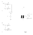
- the control of the switching elements S1, S2, S3, S4 is preferably carried out via optocouplers 01, 02, 03, 04, as in Fig. 2 shown, so that the computers are galvanically isolated from the switching elements.
- the transformer T a rectifier G downstream.
- the two computers MK1, MK2 are connected to each other via a data line L with a resistor R in safety construction and can be synchronized with each other.
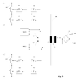
- monitoring elements U1, U2, U3, U4 are provided, which may for example be designed as an optocoupler and for monitoring the switching states of the switching elements S1, S2, S3, S4 are used during operation. To do this detected by the monitoring elements U1, U2, U3, U4 switching state signals that are transmitted to the corresponding switching element controlling computer. Turning off a channel to test the operability of the corresponding channel is not necessary in this embodiment due to the cyclic changing of the states of all the switching elements.
- the switching state signals to the other computer ie the computer that is not responsible for the control of the corresponding switching element
- the first computer MK1 is connected to the monitoring elements U3, U4 and the second computer MK2 with the monitoring elements U1, U2 via one line with a resistor R1, R2 in safety design.
- the inventive alternating power supply of a transformer by means of an H-bridge circuit whose switching elements are controlled by two independent computers a simple and reliable control of safety-related components is realized, with a safe shutdown is guaranteed in case of failure of a switching element or a computer.
Landscapes
- Engineering & Computer Science (AREA)
- Mechanical Engineering (AREA)
- Power Engineering (AREA)
- Automation & Control Theory (AREA)
- Train Traffic Observation, Control, And Security (AREA)
- Safety Devices In Control Systems (AREA)
Abstract
Eine Steuervorrichtung zur Steuerung einer sicherheitsrelevanten Komponente, wobei die Steuervorrichtung umfasst: einen Transformator zur Ausgabe eines Steuersignals, eine H-Brückenschaltung mit zwei Schaltzweigen und einem Brückenzweig, wobei jeder Schaltzweig ein Schaltelemente-Paar bestehend aus zwei in Serie geschalteten Schaltelementen und der Brückenzweig als Last eine Primärspule des Transformators umfasst, und zwei voneinander unabhängige synchronisierte Rechner, wobei jeder Rechner eines der Schaltelemente-Paare mit Hilfe von Steuerelementen steuert, wobei die Rechner dazu eingerichtet sind, im Falle eines Schaltbefehls die Schaltelemente jedes Schaltelement-Paares abwechselnd in einer vorgegebenen Frequenz zu öffnen und zu schließen, so dass der Transformator mit einer Wechselspannung der vorgegeben Frequenz versorgt wird. Dadurch wird eine robuste und wenig fehleranfällige Steuervorrichtung bereitgestellt, mit der ein hohes Sicherheitslevel realisiert werden kann.A control device for controlling a safety-related component, the control device comprising: a transformer for outputting a control signal, an H-bridge circuit having two switching branches and a bridge branch, each switching branch comprising a switching element pair consisting of two series-connected switching elements and the bridge branch as load a primary coil of the transformer comprises, and two independent synchronized computer, each computer controls one of the switching element pairs by means of controls, wherein the computers are adapted to the switching elements of each switching element pair alternately in a predetermined frequency in the case of a switching command open and close, so that the transformer is supplied with an AC voltage of the predetermined frequency. As a result, a robust and less error-prone control device is provided with which a high level of security can be realized.
Description
Die Erfindung betrifft eine Steuervorrichtung sowie ein Verfahren zur Steuerung einer sicherheitsrelevanten Komponente.The invention relates to a control device and a method for controlling a safety-relevant component.
Für die Steuerung von Systemen mit sicherheitsrelevanten Komponenten (z. B. Achszähler, Signallampen, Schranken usw.), insbesondere bei Eisenbahnsicherungsanlagen ist es wichtig, im Falle eines Ausfalls der sicherheitsrelevanten Komponente das System in einen sicheren Zustand zu überführen, um so die Sicherheit der Verkehrsteilnehmer zu gewährleisten.For the control of systems with safety - relevant components (eg axle counters, signal lamps, barriers, etc.), especially in railway safety systems, it is important to transfer the system to a safe state in the event of a failure of the safety - relevant component in order to ensure the safety of the system To ensure road users.
Aus
.Darüber hinaus ist ein Achszähler (Az LM) der Firma Thales Transportation Systems GmbH bekannt, der eine zweikanalige Steuervorrichtung mit parallelen Relaisschnittstellen aufweist. Diese Vorrichtung ist jedoch anfällig für Verschleiß und Vibrationen, wodurch Kontakte der Relais gelöst werden können. Zudem besteht die Gefahr, dass der Rückstellmechanismus der Relais verklemmt, so dass die benötigte Zuverlässigkeit nur mit einem hohen Aufwand an Wartung gewährleistet werden kann.In addition, an axle counter (Az LM) from Thales Transportation Systems GmbH is known, which has a dual-channel control device with parallel relay interfaces. However, this device is susceptible to wear and vibration, whereby contacts of the relay can be solved. In addition, there is a risk that the return mechanism of the relay jammed, so that the required reliability can be ensured only with a high cost of maintenance.
Es ist Aufgabe der Erfindung eine Steuervorrichtung und ein Verfahren zum Steuern einer sicherheitsrelevanten Komponente vorzuschlagen, die wenig fehleranfällig sind und mit denen ein hohes Sicherheitsniveau realisiert werden kann.It is an object of the invention to propose a control device and a method for controlling a safety-relevant component, which are not susceptible to errors and with which a high level of security can be realized.
Diese Aufgabe wird erfindungsgemäß gelöst durch eine Steuervorrichtung gemäß Patentanspruch 1 sowie ein Verfahren gemäß Patentanspruch 13.This object is achieved by a control device according to
Die erfindungsgemäße Steuervorrichtung umfasst einen Transformator zur Ausgabe eines Steuersignals, eine H-Brückenschaltung mit zwei Schaltzweigen und einem Brückenzweig, wobei jeder Schaltzweig ein Schaltelemente-Paar bestehend aus zwei in Serie geschalteten Schaltelementen und der Brückenzweig als Last eine Primärspule des Transformators umfasst. Die erfindungsgemäße Steuervorrichtung umfasst weiterhin zwei voneinander unabhängige, synchronisierte Rechner, wobei jeder Rechner eines der Schaltelemente-Paare mit Hilfe von Steuerelementen, z.B. I/O-Ports steuert, wobei die Rechner dazu eingerichtet sind, im Falle eines Schaltbefehls die Schaltelemente jedes Schaltelement-Paares abwechselnd in einer vorgegebenen Frequenz zu öffnen und zu schließen, so dass der Transformator mit einer Wechselspannung der vorgegebenen Frequenz versorgt wird.The control device according to the invention comprises a transformer for outputting a control signal, an H-bridge circuit with two switching branches and a bridge branch, each switching branch comprising a switching element pair consisting of two series-connected switching elements and the bridge branch as load a primary coil of the transformer. The control device according to the invention further comprises two independent, synchronized computers, each computer operating one of the switching element pairs by means of control elements, e.g. In the case of a switching command, the computers are arranged to alternately open and close the switching elements of each switching element pair at a predetermined frequency, so that the transformer is supplied with an alternating voltage of the predetermined frequency.
Die Steuerelemente werden von den Rechnern so angesteuert, dass in jedem Schaltelement-Paar zu jeder Zeit jeweils ein Schaltelement geöffnet und ein Schaltelement geschlossen ist. Um die Schaltbefehle der beiden Rechner an die Schaltelemente aufeinander abzustimmen, sind die beiden Rechner synchronisiert. Zusätzlich zu jedem Schaltelemente-Paar können in jedem Schaltzweig weitere Schaltelemente vorhanden sein, insbesondere um die Verfügbarkeit zu erhöhen (Redundanz).The controls are controlled by the computers so that each time a switching element is opened in each switching element pair and a switching element is closed. In order to match the switching commands of the two computers to the switching elements, the two computers are synchronized. In addition to each switching element pair, further switching elements may be present in each switching branch, in particular in order to increase the availability (redundancy).
Transformatoren haben die unverlierbare physikalische Eigenschaft, dass eine Energieübertragung nur bei Beaufschlagung mit Wechselstrom erfolgt. Durch die erfindungsgemäße Ansteuerung der H-Brücke (Transistorbrücke) wird eine Wechselspannung erzeugt, wodurch über den Transformator ein Steuersignal an die zu steuernde sicherheitsrelevante Komponente ausgegeben wird. Gemäß der Erfindung wird der Transformator gemeinsam von zwei (im Sinne der zum Anmeldezeitpunkt geltenden Norm DIN EN 50129) unabhängigen Rechnern (Mikrokontroller) gesteuert, wobei jeder Rechner einen Spannungspol des Transformators steuert. Wenn einer der Rechner keinen Schaltbefehl mehr ausgibt, oder einer der Schalter nicht mehr schaltet, wird der Strom in der Primärspule nicht mehr umgepolt und es findet keine Energieübertragung im Trafo mehr statt bzw. die vom Transformator ausgegebene Spannung fällt auf einen sehr kleinen Wert ab, wodurch ein Abschalten des Stromflusses durch die Steuervorrichtung initiiert werden kann. Die Steuervorrichtung macht sich also selbst wirkungslos und wird somit in einen sicheren Zustand überführt. Auf diese Weise kann das für bahnsicherheitstechnische Komponenten erforderliche SIL4-Level erreicht werden.Transformers have the indelible physical property that energy transfer occurs only when exposed to alternating current. The inventive control of the H-bridge (transistor bridge) generates an alternating voltage, whereby a control signal is output to the safety-relevant component to be controlled via the transformer. According to the invention, the transformer is jointly controlled by two computers (microcontrollers) independent of each other (in the sense of the standard DIN EN 50129 valid at the time of application), each computer controlling a voltage pole of the transformer. If one of the calculators no more switching command outputs, or one of the switch no longer switches, the current in the primary coil is no longer reversed and there is no energy transfer in the transformer more or the voltage output from the transformer drops to a very small value, causing a shutdown of the Current flow can be initiated by the control device. The control device thus makes itself ineffective and is thus transferred to a safe state. In this way, the SIL4 level required for railway safety components can be achieved.
Vorzugsweise sind Überwachungselemente zur Überwachung der Schaltzustände der Schaltelemente vorhanden. Die Überwachungselemente detektieren ein Signal betreffend den Schaltzustand des jeweiligen Schaltelements, welches an den zugehörigen Rechner (also den Rechner, der für die Steuerung des betreffenden Schaltelements zuständig ist) übermittelt wird, so dass kontrolliert werden kann, ob das Schaltelement korrekt funktioniert. Dies erfolgt im Allgemeinen durch Vergleich des Schaltzustands, der anhand des übermittelten Signals ermittelt wurde, mit einem Soll-Schaltzustand, der im Rechner hinterlegt ist).Preferably, monitoring elements for monitoring the switching states of the switching elements are present. The monitoring elements detect a signal relating to the switching state of the respective switching element, which is transmitted to the associated computer (that is, the computer which is responsible for the control of the relevant switching element), so that it can be checked whether the switching element is working properly. This is generally done by comparing the switching state, which was determined on the basis of the transmitted signal, with a desired switching state, which is stored in the computer).
Eine Weiterbildung dieser Ausführungsform sieht vor, dass die Überwachungselemente jeweils mit beiden Rechnern verbunden sind zur Übertragung eines den Schaltzustand des jeweiligen Schaltelements betreffenden Signals an beide Rechner. Dies stellt eine Möglichkeit dar, die Rechner zu synchronisieren. Die Sicherheit kann weiter erhöht werden wenn einer der Rechner keine Schaltbefehle mehr ausgibt, sobald er erkennt, dass der andere Rechner keine Schaltbefehle mehr ausgibt oder die ihm zugeordneten Schaltelemente nicht mehr schalten.A further development of this embodiment provides that the monitoring elements are each connected to both computers for transmitting a signal relating to the switching state of the respective switching element to both computers. This provides a way to synchronize the computers. The security can be further increased if one of the computer no longer issues switching commands as soon as it detects that the other computer no longer issues switching commands or no longer switch the switching elements assigned to it.
Um trotz der Verbindung der beiden Rechner über die Überwachungselemente die Unabhängigkeit der beiden Rechner zu gewährleisten, ist bei einer bevorzugten Ausführungsform vorgesehen, dass die von einem der Rechner angesteuerten Schaltelemente über Leitungen mit jeweils einem Widerstand in Sicherheitsbauform mit dem jeweils anderen Rechner verbunden sind. Durch die Sicherheitsbauweise wird garantiert, dass sich bei einem Defekt der Widerstandswert nur erhöhen, jedoch nicht verringern kann, so dass ein Kurzschluss sicher vermieden werden kann. "Garantiert" bedeutet in diesem Zusammenhang, dass die Wahrscheinlichkeit für eine Widerstandsverringerung so extrem klein ist, dass man dieses Ereignis als ausgeschlossen betrachtet. Diese Eigenschaft des Bauelements gilt als unverlierbar, solange keine Überlastung des Bauelementes eintritt. Der Überlastungsfall muss daher durch die Schaltung und Dimensionierung der Bauelemente ausgeschlossen werden.In order to ensure the independence of the two computers despite the connection of the two computers on the monitoring elements, it is provided in a preferred embodiment that the one of the computer controlled switching elements via lines, each with a resistor in safety design with the other computer connected are. The safety design guarantees that the resistance can only increase but not decrease in the event of a defect, so that a short circuit can be safely avoided. "Guaranteed" in this context means that the probability of a drag reduction is so extremely small that one considers this event to be excluded. This property of the device is considered captive as long as no overloading of the component occurs. The overload case must therefore be excluded by the circuit and dimensioning of the components.
Bei einer besonders bevorzugten Ausführungsform sind die Überwachungselemente Optokoppler, die jeweils parallel zu einem der Schaltelemente geschaltet sind. Die Schaltelemente können dadurch galvanisch getrennt von dem entsprechenden Rechner angesteuert werden.In a particularly preferred embodiment, the monitoring elements are optocouplers, which are each connected in parallel to one of the switching elements. The switching elements can thereby be controlled electrically isolated from the corresponding computer.
Zur Synchronisation können die beiden Rechner über eine Datenleitung miteinander verbunden sein. Informationen betreffend die Schaltbefehle zum Umschalten der Schaltelemente können somit direkt zwischen den beiden Rechnern ausgetauscht werden (alternativ oder zusätzlich zur Informationsübertragung der Überwachungselemente an beide Rechner).For synchronization, the two computers can be connected to each other via a data line. Information regarding the switching commands for switching the switching elements can thus be exchanged directly between the two computers (alternatively or additionally to the information transmission of the monitoring elements to both computers).
Darüber hinaus kann es vorteilhaft sein, wenn die beiden Rechner als Master-Slave-Konfiguration ausgebildet sind.In addition, it may be advantageous if the two computers are designed as a master-slave configuration.
Vorzugsweise liegt eine galvanische Trennung zwischen den beiden Rechnern und/oder zwischen jeweils einem Rechner und den von diesem Rechner angesteuerten Schaltelementen vor. Hierdurch können Fehlerquellen minimiert werden.Preferably there is a galvanic isolation between the two computers and / or between in each case a computer and the switching elements controlled by this computer. This can minimize sources of error.
Eine galvanische Trennung zwischen Rechnern und Schaltelementen kann beispielsweise dadurch realisiert werden, dass als Steuerelemente Optokoppler dienen. Durch die inhärenten Eigenschaften der Optokoppler sind Rechner und Schaltelemente galvanisch voneinander getrennt und eine Datenübertragung kann nur in einer Richtung erfolgen. Eine Manipulation der Datenübertragungsrichtung in den Mikrokontrollern durch Software kann somit ausgeschlossen werden. Alternativ hierzu können als Steuerelemente auch Übertrager zum Einsatz kommen.A galvanic separation between computers and switching elements can be realized, for example, that serve as controls optocouplers. Due to the inherent properties of the optocouplers computer and switching elements are galvanically separated from each other and data transmission can only be done in one direction. A manipulation of the data transmission direction in the microcontrollers by software can thus excluded. Alternatively, transformers can be used as controls.
Bei einer besonders bevorzugten Ausführungsform ist dem Transformator ein Gleichrichter nachgeschaltet. Somit können sicherheitsrelevante Komponenten mit Gleichstrom betrieben werden. Dies ist insbesondere dort vorteilhaft, wo ein sicherer Zustand hergestellt werden kann, indem die Elektronik ausgeschaltet wird. Also z.B. für den Betrieb von LED-Signalen (sicherer Zustand = LED aus), für die Ansteuerung von Gleichstromrelais (sicherer Zustand = Relais stromlos), für die Versorgungsspannung für sichere Rechnersysteme (sicherer Zustand = Rechner abgeschaltet) oder für die Erzeugung von Fernsteuersignalen mit Vorzugsausfallrichtung (Signalleitung kann bei Defekt der Steuereinheit nicht im EIN-Zustand verbleiben, sondern wird IMMER in den AUS-Zustand wechseln; z. B. für Block-Information "Strecke frei", Ansteuerung von Bahnübergängen mit automatischem Schließen bei Ausfall der Fernsteuerung, usw.). Ein "sicherer Zustand" bedeutet dabei ein Verhalten der Technik, welches keine Gefährdung des Betriebs (Personen und Material) darstellt und welches unabhängig vom aufgetretenen Fehler immer erreichbar ist.In a particularly preferred embodiment, the transformer is followed by a rectifier. Thus, safety-related components can be operated with direct current. This is particularly advantageous where a safe state can be established by turning off the electronics. So, for example for the operation of LED signals (safe state = LED off), for the control of DC relays (safe state = relay de-energized), for the supply voltage for secure computer systems (safe state = computer switched off) or for the generation of remote control signals with preferential failure direction ( Signal line can not remain in the ON state if the control unit is defective, but ALWAYS will switch to the OFF state, eg for block information "route free", control of level crossings with automatic closing in case of failure of the remote control, etc.) , A "safe state" means a behavior of the technology which does not represent any danger to the operation (persons and material) and which is always attainable regardless of the error that has occurred.
Die Vorteile der Erfindung kommen besonders zur Geltung, wenn die Steuervorrichtung Teil einer Achszählvorrichtung ist.The advantages of the invention are particularly effective when the control device is part of a Achszählvorrichtung.
Die Erfindung findet vorzugsweise im Bahnbereich Anwendung. Die sicherheitsrelevante Komponente kann dann beispielsweise eine Signallampe, eine Gleisfreimeldeanlage oder eine Bahnübergangsschranke sein.The invention is preferably used in the railway sector. The safety-relevant component can then be, for example, a signal lamp, a train detection system or a level crossing gate.
Die Erfindung betrifft auch ein Verfahren zur Steuerung einer sicherheitsrelevanten Komponente mit einer zuvor beschriebenen Steuervorrichtung, wobei die Rechner der Steuervorrichtung im Falle eines eingegebenen Schaltbefehls die Schaltelemente jedes Schaltelement-Paares abwechselnd in einer vorgegebenen Frequenz öffnen und schließen, so dass der Transformator mit einer Wechselspannung der vorgegebenen Frequenz versorgt wird.The invention also relates to a method for controlling a safety-relevant component with a control device described above, wherein the computer of the control device in the case of an input switching command, the switching elements of each switching element pair alternately open and close in a predetermined frequency, so that the transformer with an AC voltage of predetermined frequency is supplied.
Weitere Vorteile der Erfindung ergeben sich aus der Beschreibung und der Zeichnung. Ebenso können die vorstehend genannten und die noch weiter ausgeführten Merkmale erfindungsgemäß jeweils einzeln für sich oder zu mehreren in beliebigen Kombinationen Verwendung finden. Die gezeigten und beschriebenen Ausführungsformen sind nicht als abschließende Aufzählung zu verstehen, sondern haben vielmehr beispielhaften Charakter für die Schilderung der Erfindung.Further advantages of the invention will become apparent from the description and the drawings. Likewise, according to the invention, the above-mentioned features and those which are still further developed can each be used individually for themselves or for a plurality of combinations of any kind. The embodiments shown and described are not to be understood as exhaustive enumeration, but rather have exemplary character for the description of the invention.
- Fig. 1Fig. 1
- zeigt eine erste Ausführungsform der erfindungsgemäßen Steuervorrichtung mit Synchronisation über eine Datenleitung.shows a first embodiment of the control device according to the invention with synchronization via a data line.
- Fig. 2Fig. 2
-
zeigt eine Weiterbildung der in
Fig. 1 gezeigten Ausführungsform der erfindungsgemäßen Steuervorrichtung mit Ansteuerung der Schalter über Optokoppler und Gleichrichter.shows a further education inFig. 1 shown embodiment of the control device according to the invention with control of the switch via optocouplers and rectifier. - Fig. 3Fig. 3
- zeigt eine weitere Ausführungsform der erfindungsgemäßen Steuervorrichtung mit Synchronisation über Überwachungselemente.shows a further embodiment of the control device according to the invention with synchronization via monitoring elements.
- Fig. 4Fig. 4
-
zeigt eine Weiterbildung der in
Fig. 3 gezeigten Ausführungsform der erfindungsgemäßen Steuervorrichtung mit zusätzlicher Synchronisation über eine Datenleitung.shows a further education inFig. 3 shown embodiment of the control device according to the invention with additional synchronization via a data line.
Die erfindungsgemäße Steuervorrichtung umfasst eine H-Brückenschaltung mit zwei Schaltzweigen SZ1, SZ2 und einem Brückenzweig BZ. In jedem Schaltzweig SZ1, SZ2 ist ein Schaltelemente-Paar S1/S2, S3/S4 mit jeweils zwei in Serie geschalteten Schaltelementen S1, S2, S3, S4 angeordnet. Die H-Brückenschaltung wird über eine Gleichspannungsquelle mit Strom versorgt, wobei von jedem Schaltelemente-Paar S1/S2, S3/S4 jeweils ein Schaltelement S1, S3 am Pluspol und das andere Schaltelement S2, S4 am Minuspol der Spannungsquelle angeschlossen ist. Die Schalter S1, S2 des ersten Schaltelement-Paares S1/S2 werden von einem ersten Rechner MK1, die Schalter S3, S4 des zweiten Schaltelement-Paares S3/S4 von einem zweiten Rechner MK2 angesteuert. Mittels der Schaltelemente S1, S2, S3, S4 wird ein Transformator T mit Wechselspannung versorgt, dessen Primärspule P Teil des Brückenzweiges BZ der H-Brückenschaltung (Last) ist. Dazu schalten die beiden Rechner MK1, MK2 die Schaltelemente S1, S2, S3, S4 so, dass abwechselnd entweder die Schaltelemente S1 und S4 oder die Schaltelemente S2 und S3 gemeinsam geschlossen sind, so dass Strom durch die Primärspule P des Transformators T fließt. Durch zyklisches Ändern der Schaltungszustände der Schaltelemente S1, S2, S3, S4 wird ein Wechselstrom durch den Transformator T erzeugt und der Transformator T kann ein Steuersignal an eine zu steuernde Komponente (nicht gezeigt) abgeben. Die Schaltfrequenz der Schaltelemente und damit die dadurch erzeugte Wechselspannung beträgt mindestens 1kHz, vorzugsweise mehr als 50 kHz und ist begrenzt durch die Synchronisierungsfrequenz und Transformatoreigenschaften, insbesondere Induktivität der Spulen und Hysterese des Eisenkerns.The control device according to the invention comprises an H-bridge circuit with two switching branches SZ1, SZ2 and a bridge branch BZ. In each switching branch SZ1, SZ2 a switching element pair S1 / S2, S3 / S4 is arranged with two switching elements S1, S2, S3, S4 connected in series. The H bridge circuit is supplied with power via a DC voltage source, one switching element S1, S3 at the positive pole and the other switching element S2, S4 at each of each switching element pair S1 / S2, S3 / S4 Negative pole of the voltage source is connected. The switches S1, S2 of the first switching element pair S1 / S2 are controlled by a first computer MK1, the switches S3, S4 of the second switching element pair S3 / S4 by a second computer MK2 . By means of the switching elements S1, S2, S3, S4, a transformer T is supplied with AC voltage whose primary coil P is part of the bridge branch BZ of the H-bridge circuit (load). For this purpose, the two computers MK1, MK2 switch the switching elements S1, S2, S3, S4 so that either the switching elements S1 and S4 or the switching elements S2 and S3 are alternately closed together so that current flows through the primary coil P of the transformer T. By cyclically changing the circuit states of the switching elements S1, S2, S3, S4, an alternating current is generated by the transformer T and the transformer T can output a control signal to a component to be controlled (not shown). The switching frequency of the switching elements and thus the AC voltage generated thereby is at least 1 kHz, preferably more than 50 kHz and is limited by the synchronization frequency and transformer properties, in particular inductance of the coils and hysteresis of the iron core.
Die Ansteuerung der Schaltelemente S1, S2, S3, S4 erfolgt vorzugsweise über Optokoppler 01, 02, 03, 04, wie in
Um die anzusteuernde sicherheitsrelevante Komponente mit Gleichstrom zu betreiben, ist bei der in
Bei den in
In den in
Durch die erfindungsgemäße abwechselnde Stromversorgung eines Transformators mittels einer H-Brückenschaltung, deren Schaltelemente über zwei unabhängige Rechner gesteuert werden, wird eine einfache und zuverlässige Ansteuerung von sicherheitsrelevanten Komponenten realisiert, wobei ein sicheres Abschalten bei Ausfall eines Schaltelements oder eines Rechners gewährleistet ist.The inventive alternating power supply of a transformer by means of an H-bridge circuit whose switching elements are controlled by two independent computers, a simple and reliable control of safety-related components is realized, with a safe shutdown is guaranteed in case of failure of a switching element or a computer.
- BZBZ
- Brückenzweigbridge branch
- GG
- Gleichrichterrectifier
- LL
- Datenleitungdata line
- MK1, MK2MK1, MK2
- Rechnercomputer
- O1, O2, O3, O4O1, O2, O3, O4
- Optokoppleroptocoupler
- PP
- Primärspuleprimary coil
- R, R1, R2R, R1, R2
- Widerstände in SicherheitsbauformResistors in safety design
- S1, S2S1, S2
- Schaltelemente des ersten Schaltelemente-PaarsSwitching elements of the first switching element pair
- S3, S4S3, S4
- Schaltelemente des zweiten Schaltelemente-PaarsSwitching elements of the second switching element pair
- SZ1, SZ2SZ1, SZ2
- Schaltzweigenswitching branches
- TT
- Transformatortransformer
- U1, U2, U3, U4U1, U2, U3, U4
- Überwachungselementemonitoring elements
Claims (13)
Priority Applications (4)
| Application Number | Priority Date | Filing Date | Title |
|---|---|---|---|
| ES15181147.8T ES2693090T3 (en) | 2015-08-14 | 2015-08-14 | Control device and procedure for the control of a component relevant for safety |
| EP15181147.8A EP3131192B1 (en) | 2015-08-14 | 2015-08-14 | Control device and method for controlling a safety-relevant component |
| DK15181147.8T DK3131192T3 (en) | 2015-08-14 | 2015-08-14 | Control device and method for controlling a safety-relevant component |
| HRP20181750TT HRP20181750T1 (en) | 2015-08-14 | 2018-10-24 | Control device and method for controlling a safety-relevant component |
Applications Claiming Priority (1)
| Application Number | Priority Date | Filing Date | Title |
|---|---|---|---|
| EP15181147.8A EP3131192B1 (en) | 2015-08-14 | 2015-08-14 | Control device and method for controlling a safety-relevant component |
Publications (2)
| Publication Number | Publication Date |
|---|---|
| EP3131192A1 true EP3131192A1 (en) | 2017-02-15 |
| EP3131192B1 EP3131192B1 (en) | 2018-10-03 |
Family
ID=53879385
Family Applications (1)
| Application Number | Title | Priority Date | Filing Date |
|---|---|---|---|
| EP15181147.8A Active EP3131192B1 (en) | 2015-08-14 | 2015-08-14 | Control device and method for controlling a safety-relevant component |
Country Status (4)
| Country | Link |
|---|---|
| EP (1) | EP3131192B1 (en) |
| DK (1) | DK3131192T3 (en) |
| ES (1) | ES2693090T3 (en) |
| HR (1) | HRP20181750T1 (en) |
Citations (3)
| Publication number | Priority date | Publication date | Assignee | Title |
|---|---|---|---|---|
| DE3003291C2 (en) | 1980-01-30 | 1983-02-24 | Siemens AG, 1000 Berlin und 8000 München | Two-channel data processing arrangement for railway safety purposes |
| WO2002015363A2 (en) * | 2000-08-18 | 2002-02-21 | Hochschule Technik + Architektur Luzern | Current-accumulator module comprising batteries and capacitors, in particular, supercapacitors |
| US8937822B2 (en) * | 2011-05-08 | 2015-01-20 | Paul Wilkinson Dent | Solar energy conversion and utilization system |
-
2015
- 2015-08-14 ES ES15181147.8T patent/ES2693090T3/en active Active
- 2015-08-14 DK DK15181147.8T patent/DK3131192T3/en active
- 2015-08-14 EP EP15181147.8A patent/EP3131192B1/en active Active
-
2018
- 2018-10-24 HR HRP20181750TT patent/HRP20181750T1/en unknown
Patent Citations (3)
| Publication number | Priority date | Publication date | Assignee | Title |
|---|---|---|---|---|
| DE3003291C2 (en) | 1980-01-30 | 1983-02-24 | Siemens AG, 1000 Berlin und 8000 München | Two-channel data processing arrangement for railway safety purposes |
| WO2002015363A2 (en) * | 2000-08-18 | 2002-02-21 | Hochschule Technik + Architektur Luzern | Current-accumulator module comprising batteries and capacitors, in particular, supercapacitors |
| US8937822B2 (en) * | 2011-05-08 | 2015-01-20 | Paul Wilkinson Dent | Solar energy conversion and utilization system |
Also Published As
| Publication number | Publication date |
|---|---|
| ES2693090T3 (en) | 2018-12-07 |
| DK3131192T3 (en) | 2018-12-03 |
| HRP20181750T1 (en) | 2018-12-28 |
| EP3131192B1 (en) | 2018-10-03 |
Similar Documents
| Publication | Publication Date | Title |
|---|---|---|
| EP1058093A1 (en) | Method and circuit for powering and monitoring the functioning of at least one sensor | |
| DE4140587C2 (en) | Electronic control device for switching multiple electrical loads | |
| DE102012103015A1 (en) | Safety switching device with switching element in the auxiliary contact current path | |
| DE2711416C2 (en) | Arrangement for displaying the switching status of the switches | |
| EP2587512B1 (en) | Safety-oriented switching device | |
| DE2651314C2 (en) | Safety output circuit for a data processing system that emits binary signals | |
| DE102006047469B4 (en) | Method and device for checking a switch arrangement | |
| DE102014100970A1 (en) | Method and device for safely switching off an electrical load | |
| EP2590036B2 (en) | Safety switching device | |
| EP3131192B1 (en) | Control device and method for controlling a safety-relevant component | |
| DE102006030911B3 (en) | Relay unit for use in electrical or in electronic circuits, devices and components, has switching arrangement, consisting of two relay coils with separate contact sets per relay coil, fault indicator coil and additional working contact | |
| DE102016121255A1 (en) | Control module for an electromechanical switching unit, relay module and control device | |
| DE3638681C2 (en) | ||
| EP2127992A2 (en) | Circuit for monitoring the end position switches of a four wire three phase drive for points | |
| DE102011122363B4 (en) | Electric control for electromagnets | |
| EP2988419A1 (en) | Method for determining the state of a reporting element which forms a short circuit | |
| DE102013003766B3 (en) | Method for replacing small pole relay in direct current/alternating current transmission circuits of railway signaling, involves amplifying falling voltage of replacement resistors and energizing increased voltage of replacement relay | |
| AT413307B (en) | DIGITAL INPUT MODULE | |
| EP3667339A1 (en) | Online control for capacitors of capacitor banks | |
| WO2011157512A2 (en) | Power supply unit for signal luminaires | |
| EP2820738B1 (en) | Multifunctional i/o device | |
| DE3029851A1 (en) | CIRCUIT ARRANGEMENT FOR THE SIGNAL TECHNOLOGY SAFE CONTROL OF A POWER CONSUMER | |
| EP1134715B1 (en) | Lamp circuit for a signalisation device of a traffic signal system | |
| DE2524296C3 (en) | Circuit arrangement for the self-safe remote control of electrical consumers from a control point, in particular for track magnets of inductive train protection | |
| DE1208659B (en) | Circuit arrangement for monitoring mutually exclusive signal states for road traffic signal systems |
Legal Events
| Date | Code | Title | Description |
|---|---|---|---|
| PUAI | Public reference made under article 153(3) epc to a published international application that has entered the european phase |
Free format text: ORIGINAL CODE: 0009012 |
|
| STAA | Information on the status of an ep patent application or granted ep patent |
Free format text: STATUS: THE APPLICATION HAS BEEN PUBLISHED |
|
| AK | Designated contracting states |
Kind code of ref document: A1 Designated state(s): AL AT BE BG CH CY CZ DE DK EE ES FI FR GB GR HR HU IE IS IT LI LT LU LV MC MK MT NL NO PL PT RO RS SE SI SK SM TR |
|
| AX | Request for extension of the european patent |
Extension state: BA ME |
|
| STAA | Information on the status of an ep patent application or granted ep patent |
Free format text: STATUS: REQUEST FOR EXAMINATION WAS MADE |
|
| 17P | Request for examination filed |
Effective date: 20170815 |
|
| RBV | Designated contracting states (corrected) |
Designated state(s): AL AT BE BG CH CY CZ DE DK EE ES FI FR GB GR HR HU IE IS IT LI LT LU LV MC MK MT NL NO PL PT RO RS SE SI SK SM TR |
|
| STAA | Information on the status of an ep patent application or granted ep patent |
Free format text: STATUS: EXAMINATION IS IN PROGRESS |
|
| RAP1 | Party data changed (applicant data changed or rights of an application transferred) |
Owner name: THALES MANAGEMENT & SERVICES DEUTSCHLAND GMBH |
|
| 17Q | First examination report despatched |
Effective date: 20171129 |
|
| GRAP | Despatch of communication of intention to grant a patent |
Free format text: ORIGINAL CODE: EPIDOSNIGR1 |
|
| STAA | Information on the status of an ep patent application or granted ep patent |
Free format text: STATUS: GRANT OF PATENT IS INTENDED |
|
| INTG | Intention to grant announced |
Effective date: 20180416 |
|
| GRAS | Grant fee paid |
Free format text: ORIGINAL CODE: EPIDOSNIGR3 |
|
| GRAA | (expected) grant |
Free format text: ORIGINAL CODE: 0009210 |
|
| STAA | Information on the status of an ep patent application or granted ep patent |
Free format text: STATUS: THE PATENT HAS BEEN GRANTED |
|
| AK | Designated contracting states |
Kind code of ref document: B1 Designated state(s): AL AT BE BG CH CY CZ DE DK EE ES FI FR GB GR HR HU IE IS IT LI LT LU LV MC MK MT NL NO PL PT RO RS SE SI SK SM TR |
|
| REG | Reference to a national code |
Ref country code: GB Ref legal event code: FG4D Free format text: NOT ENGLISH |
|
| REG | Reference to a national code |
Ref country code: AT Ref legal event code: REF Ref document number: 1049702 Country of ref document: AT Kind code of ref document: T Effective date: 20181015 Ref country code: CH Ref legal event code: EP |
|
| REG | Reference to a national code |
Ref country code: HR Ref legal event code: TUEP Ref document number: P20181750 Country of ref document: HR |
|
| REG | Reference to a national code |
Ref country code: DE Ref legal event code: R096 Ref document number: 502015006203 Country of ref document: DE Ref country code: IE Ref legal event code: FG4D Free format text: LANGUAGE OF EP DOCUMENT: GERMAN |
|
| REG | Reference to a national code |
Ref country code: DK Ref legal event code: T3 Effective date: 20181129 |
|
| REG | Reference to a national code |
Ref country code: ES Ref legal event code: FG2A Ref document number: 2693090 Country of ref document: ES Kind code of ref document: T3 Effective date: 20181207 |
|
| REG | Reference to a national code |
Ref country code: HR Ref legal event code: T1PR Ref document number: P20181750 Country of ref document: HR |
|
| REG | Reference to a national code |
Ref country code: NL Ref legal event code: FP |
|
| REG | Reference to a national code |
Ref country code: NO Ref legal event code: T2 Effective date: 20181003 Ref country code: LT Ref legal event code: MG4D |
|
| PG25 | Lapsed in a contracting state [announced via postgrant information from national office to epo] |
Ref country code: CZ Free format text: LAPSE BECAUSE OF FAILURE TO SUBMIT A TRANSLATION OF THE DESCRIPTION OR TO PAY THE FEE WITHIN THE PRESCRIBED TIME-LIMIT Effective date: 20181003 Ref country code: LT Free format text: LAPSE BECAUSE OF FAILURE TO SUBMIT A TRANSLATION OF THE DESCRIPTION OR TO PAY THE FEE WITHIN THE PRESCRIBED TIME-LIMIT Effective date: 20181003 Ref country code: IS Free format text: LAPSE BECAUSE OF FAILURE TO SUBMIT A TRANSLATION OF THE DESCRIPTION OR TO PAY THE FEE WITHIN THE PRESCRIBED TIME-LIMIT Effective date: 20190203 Ref country code: PL Free format text: LAPSE BECAUSE OF FAILURE TO SUBMIT A TRANSLATION OF THE DESCRIPTION OR TO PAY THE FEE WITHIN THE PRESCRIBED TIME-LIMIT Effective date: 20181003 Ref country code: LV Free format text: LAPSE BECAUSE OF FAILURE TO SUBMIT A TRANSLATION OF THE DESCRIPTION OR TO PAY THE FEE WITHIN THE PRESCRIBED TIME-LIMIT Effective date: 20181003 |
|
| PG25 | Lapsed in a contracting state [announced via postgrant information from national office to epo] |
Ref country code: AL Free format text: LAPSE BECAUSE OF FAILURE TO SUBMIT A TRANSLATION OF THE DESCRIPTION OR TO PAY THE FEE WITHIN THE PRESCRIBED TIME-LIMIT Effective date: 20181003 Ref country code: RS Free format text: LAPSE BECAUSE OF FAILURE TO SUBMIT A TRANSLATION OF THE DESCRIPTION OR TO PAY THE FEE WITHIN THE PRESCRIBED TIME-LIMIT Effective date: 20181003 Ref country code: SE Free format text: LAPSE BECAUSE OF FAILURE TO SUBMIT A TRANSLATION OF THE DESCRIPTION OR TO PAY THE FEE WITHIN THE PRESCRIBED TIME-LIMIT Effective date: 20181003 Ref country code: GR Free format text: LAPSE BECAUSE OF FAILURE TO SUBMIT A TRANSLATION OF THE DESCRIPTION OR TO PAY THE FEE WITHIN THE PRESCRIBED TIME-LIMIT Effective date: 20190104 Ref country code: PT Free format text: LAPSE BECAUSE OF FAILURE TO SUBMIT A TRANSLATION OF THE DESCRIPTION OR TO PAY THE FEE WITHIN THE PRESCRIBED TIME-LIMIT Effective date: 20190203 |
|
| REG | Reference to a national code |
Ref country code: DE Ref legal event code: R097 Ref document number: 502015006203 Country of ref document: DE |
|
| PG25 | Lapsed in a contracting state [announced via postgrant information from national office to epo] |
Ref country code: IT Free format text: LAPSE BECAUSE OF FAILURE TO SUBMIT A TRANSLATION OF THE DESCRIPTION OR TO PAY THE FEE WITHIN THE PRESCRIBED TIME-LIMIT Effective date: 20181003 |
|
| PLBE | No opposition filed within time limit |
Free format text: ORIGINAL CODE: 0009261 |
|
| STAA | Information on the status of an ep patent application or granted ep patent |
Free format text: STATUS: NO OPPOSITION FILED WITHIN TIME LIMIT |
|
| REG | Reference to a national code |
Ref country code: HR Ref legal event code: ODRP Ref document number: P20181750 Country of ref document: HR Payment date: 20190808 Year of fee payment: 5 |
|
| PG25 | Lapsed in a contracting state [announced via postgrant information from national office to epo] |
Ref country code: RO Free format text: LAPSE BECAUSE OF FAILURE TO SUBMIT A TRANSLATION OF THE DESCRIPTION OR TO PAY THE FEE WITHIN THE PRESCRIBED TIME-LIMIT Effective date: 20181003 Ref country code: SK Free format text: LAPSE BECAUSE OF FAILURE TO SUBMIT A TRANSLATION OF THE DESCRIPTION OR TO PAY THE FEE WITHIN THE PRESCRIBED TIME-LIMIT Effective date: 20181003 Ref country code: EE Free format text: LAPSE BECAUSE OF FAILURE TO SUBMIT A TRANSLATION OF THE DESCRIPTION OR TO PAY THE FEE WITHIN THE PRESCRIBED TIME-LIMIT Effective date: 20181003 Ref country code: SM Free format text: LAPSE BECAUSE OF FAILURE TO SUBMIT A TRANSLATION OF THE DESCRIPTION OR TO PAY THE FEE WITHIN THE PRESCRIBED TIME-LIMIT Effective date: 20181003 |
|
| 26N | No opposition filed |
Effective date: 20190704 |
|
| PG25 | Lapsed in a contracting state [announced via postgrant information from national office to epo] |
Ref country code: SI Free format text: LAPSE BECAUSE OF FAILURE TO SUBMIT A TRANSLATION OF THE DESCRIPTION OR TO PAY THE FEE WITHIN THE PRESCRIBED TIME-LIMIT Effective date: 20181003 |
|
| PG25 | Lapsed in a contracting state [announced via postgrant information from national office to epo] |
Ref country code: TR Free format text: LAPSE BECAUSE OF FAILURE TO SUBMIT A TRANSLATION OF THE DESCRIPTION OR TO PAY THE FEE WITHIN THE PRESCRIBED TIME-LIMIT Effective date: 20181003 |
|
| PG25 | Lapsed in a contracting state [announced via postgrant information from national office to epo] |
Ref country code: MC Free format text: LAPSE BECAUSE OF FAILURE TO SUBMIT A TRANSLATION OF THE DESCRIPTION OR TO PAY THE FEE WITHIN THE PRESCRIBED TIME-LIMIT Effective date: 20181003 |
|
| REG | Reference to a national code |
Ref country code: BE Ref legal event code: MM Effective date: 20190831 |
|
| PG25 | Lapsed in a contracting state [announced via postgrant information from national office to epo] |
Ref country code: IE Free format text: LAPSE BECAUSE OF NON-PAYMENT OF DUE FEES Effective date: 20190814 |
|
| PG25 | Lapsed in a contracting state [announced via postgrant information from national office to epo] |
Ref country code: BE Free format text: LAPSE BECAUSE OF NON-PAYMENT OF DUE FEES Effective date: 20190831 |
|
| REG | Reference to a national code |
Ref country code: HR Ref legal event code: ODRP Ref document number: P20181750 Country of ref document: HR Payment date: 20200813 Year of fee payment: 6 |
|
| PG25 | Lapsed in a contracting state [announced via postgrant information from national office to epo] |
Ref country code: CY Free format text: LAPSE BECAUSE OF FAILURE TO SUBMIT A TRANSLATION OF THE DESCRIPTION OR TO PAY THE FEE WITHIN THE PRESCRIBED TIME-LIMIT Effective date: 20181003 |
|
| PG25 | Lapsed in a contracting state [announced via postgrant information from national office to epo] |
Ref country code: MT Free format text: LAPSE BECAUSE OF FAILURE TO SUBMIT A TRANSLATION OF THE DESCRIPTION OR TO PAY THE FEE WITHIN THE PRESCRIBED TIME-LIMIT Effective date: 20181003 |
|
| REG | Reference to a national code |
Ref country code: HR Ref legal event code: ODRP Ref document number: P20181750 Country of ref document: HR Payment date: 20210812 Year of fee payment: 7 |
|
| PG25 | Lapsed in a contracting state [announced via postgrant information from national office to epo] |
Ref country code: MK Free format text: LAPSE BECAUSE OF FAILURE TO SUBMIT A TRANSLATION OF THE DESCRIPTION OR TO PAY THE FEE WITHIN THE PRESCRIBED TIME-LIMIT Effective date: 20181003 |
|
| REG | Reference to a national code |
Ref country code: HR Ref legal event code: ODRP Ref document number: P20181750 Country of ref document: HR Payment date: 20220810 Year of fee payment: 8 |
|
| REG | Reference to a national code |
Ref country code: HR Ref legal event code: ODRP Ref document number: P20181750 Country of ref document: HR Payment date: 20230728 Year of fee payment: 9 |
|
| PGFP | Annual fee paid to national office [announced via postgrant information from national office to epo] |
Ref country code: NO Payment date: 20230809 Year of fee payment: 9 Ref country code: ES Payment date: 20230905 Year of fee payment: 9 Ref country code: CH Payment date: 20230902 Year of fee payment: 9 Ref country code: AT Payment date: 20230725 Year of fee payment: 9 |
|
| PGFP | Annual fee paid to national office [announced via postgrant information from national office to epo] |
Ref country code: HU Payment date: 20230811 Year of fee payment: 9 |
|
| REG | Reference to a national code |
Ref country code: HR Ref legal event code: ODRP Ref document number: P20181750 Country of ref document: HR Payment date: 20240725 Year of fee payment: 10 |
|
| PGFP | Annual fee paid to national office [announced via postgrant information from national office to epo] |
Ref country code: LU Payment date: 20240726 Year of fee payment: 10 |
|
| PGFP | Annual fee paid to national office [announced via postgrant information from national office to epo] |
Ref country code: NL Payment date: 20240725 Year of fee payment: 10 |
|
| PGFP | Annual fee paid to national office [announced via postgrant information from national office to epo] |
Ref country code: BG Payment date: 20240730 Year of fee payment: 10 |
|
| PGFP | Annual fee paid to national office [announced via postgrant information from national office to epo] |
Ref country code: HR Payment date: 20240725 Year of fee payment: 10 Ref country code: DE Payment date: 20240717 Year of fee payment: 10 Ref country code: FI Payment date: 20240821 Year of fee payment: 10 |
|
| PGFP | Annual fee paid to national office [announced via postgrant information from national office to epo] |
Ref country code: DK Payment date: 20240813 Year of fee payment: 10 |
|
| PGFP | Annual fee paid to national office [announced via postgrant information from national office to epo] |
Ref country code: GB Payment date: 20240718 Year of fee payment: 10 |
|
| PGFP | Annual fee paid to national office [announced via postgrant information from national office to epo] |
Ref country code: FR Payment date: 20240726 Year of fee payment: 10 |