EP3131137A1 - Battery pack - Google Patents
Battery pack Download PDFInfo
- Publication number
- EP3131137A1 EP3131137A1 EP15776867.2A EP15776867A EP3131137A1 EP 3131137 A1 EP3131137 A1 EP 3131137A1 EP 15776867 A EP15776867 A EP 15776867A EP 3131137 A1 EP3131137 A1 EP 3131137A1
- Authority
- EP
- European Patent Office
- Prior art keywords
- single batteries
- end plates
- end plate
- recess
- assembled battery
- Prior art date
- Legal status (The legal status is an assumption and is not a legal conclusion. Google has not performed a legal analysis and makes no representation as to the accuracy of the status listed.)
- Granted
Links
Images



Classifications
-
- H—ELECTRICITY
- H01—ELECTRIC ELEMENTS
- H01M—PROCESSES OR MEANS, e.g. BATTERIES, FOR THE DIRECT CONVERSION OF CHEMICAL ENERGY INTO ELECTRICAL ENERGY
- H01M50/00—Constructional details or processes of manufacture of the non-active parts of electrochemical cells other than fuel cells, e.g. hybrid cells
- H01M50/20—Mountings; Secondary casings or frames; Racks, modules or packs; Suspension devices; Shock absorbers; Transport or carrying devices; Holders
- H01M50/204—Racks, modules or packs for multiple batteries or multiple cells
- H01M50/207—Racks, modules or packs for multiple batteries or multiple cells characterised by their shape
- H01M50/209—Racks, modules or packs for multiple batteries or multiple cells characterised by their shape adapted for prismatic or rectangular cells
-
- H—ELECTRICITY
- H01—ELECTRIC ELEMENTS
- H01M—PROCESSES OR MEANS, e.g. BATTERIES, FOR THE DIRECT CONVERSION OF CHEMICAL ENERGY INTO ELECTRICAL ENERGY
- H01M50/00—Constructional details or processes of manufacture of the non-active parts of electrochemical cells other than fuel cells, e.g. hybrid cells
- H01M50/20—Mountings; Secondary casings or frames; Racks, modules or packs; Suspension devices; Shock absorbers; Transport or carrying devices; Holders
- H01M50/218—Mountings; Secondary casings or frames; Racks, modules or packs; Suspension devices; Shock absorbers; Transport or carrying devices; Holders characterised by the material
- H01M50/22—Mountings; Secondary casings or frames; Racks, modules or packs; Suspension devices; Shock absorbers; Transport or carrying devices; Holders characterised by the material of the casings or racks
- H01M50/222—Inorganic material
- H01M50/224—Metals
-
- H—ELECTRICITY
- H01—ELECTRIC ELEMENTS
- H01M—PROCESSES OR MEANS, e.g. BATTERIES, FOR THE DIRECT CONVERSION OF CHEMICAL ENERGY INTO ELECTRICAL ENERGY
- H01M50/00—Constructional details or processes of manufacture of the non-active parts of electrochemical cells other than fuel cells, e.g. hybrid cells
- H01M50/20—Mountings; Secondary casings or frames; Racks, modules or packs; Suspension devices; Shock absorbers; Transport or carrying devices; Holders
- H01M50/233—Mountings; Secondary casings or frames; Racks, modules or packs; Suspension devices; Shock absorbers; Transport or carrying devices; Holders characterised by physical properties of casings or racks, e.g. dimensions
-
- H—ELECTRICITY
- H01—ELECTRIC ELEMENTS
- H01M—PROCESSES OR MEANS, e.g. BATTERIES, FOR THE DIRECT CONVERSION OF CHEMICAL ENERGY INTO ELECTRICAL ENERGY
- H01M50/00—Constructional details or processes of manufacture of the non-active parts of electrochemical cells other than fuel cells, e.g. hybrid cells
- H01M50/20—Mountings; Secondary casings or frames; Racks, modules or packs; Suspension devices; Shock absorbers; Transport or carrying devices; Holders
- H01M50/262—Mountings; Secondary casings or frames; Racks, modules or packs; Suspension devices; Shock absorbers; Transport or carrying devices; Holders with fastening means, e.g. locks
- H01M50/264—Mountings; Secondary casings or frames; Racks, modules or packs; Suspension devices; Shock absorbers; Transport or carrying devices; Holders with fastening means, e.g. locks for cells or batteries, e.g. straps, tie rods or peripheral frames
-
- Y—GENERAL TAGGING OF NEW TECHNOLOGICAL DEVELOPMENTS; GENERAL TAGGING OF CROSS-SECTIONAL TECHNOLOGIES SPANNING OVER SEVERAL SECTIONS OF THE IPC; TECHNICAL SUBJECTS COVERED BY FORMER USPC CROSS-REFERENCE ART COLLECTIONS [XRACs] AND DIGESTS
- Y02—TECHNOLOGIES OR APPLICATIONS FOR MITIGATION OR ADAPTATION AGAINST CLIMATE CHANGE
- Y02E—REDUCTION OF GREENHOUSE GAS [GHG] EMISSIONS, RELATED TO ENERGY GENERATION, TRANSMISSION OR DISTRIBUTION
- Y02E60/00—Enabling technologies; Technologies with a potential or indirect contribution to GHG emissions mitigation
- Y02E60/10—Energy storage using batteries
Definitions
- the present invention relates to an assembled battery where a plurality of rectangular batteries are stacked through fixing components.
- FIG. 8 is a view showing a conventional assembled battery described in Patent Literature 1.
- This assembled battery has a battery block 23 configured by stacking a plurality of rectangular single batteries 21, and fixing components 24 fixing the plurality of the single batteries 21.
- the fixing components 24 include a pair of end plates 25 disposed at both end surfaces of the plurality of the single batteries 21, and a metal band 26 fixing the stacked single batteries 21 in a compressed state by coupling end parts of the end plates 25.
- Patent Literature 1 Japanese Laid-Open Patent Publication No. 2008-282582 .
- the present invention provides an assembled battery where an enlargement of an outer size of the assembled battery is suppressed when the single batteries operate.
- An assembled battery of the present invention has a battery block configured by stacking a plurality of single batteries, and fixing components fixing the plurality of the single batteries.
- the fixing components include a pair of end plates disposed at both ends in a stacked direction of the plurality of the single batteries, and a metal band making the plurality of the single batteries in a compressed state by coupling end parts of the pair of the end plates each other.
- the pair of the end plates respectively contact both end single batteries located at both ends in the stacked direction at the peripheral parts, and are respectively separated from both end single batteries at the central parts.
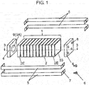
- FIG. 1 is a main configuration view of an assembled battery relating to an embodiment 1 of the present invention.
- Battery block 1 is configured by alternatively stacking single batteries 2 as a plurality of rectangular batteries (rectangular parallelepiped batteries or prismatic batteries) and separators 33.
- both sides of battery block 1 are sandwiched and fixed between end plates 4 as fixing components made of aluminum, and bolts 6 are fixed in screw taps 8 of end plates 4 through holes 7 of metal bands 5 made of steel.
- Separators 33 may be made of resin.
- FIG. 2A and FIG. 2B are front views of the end plates 4.
- recess 9 has a circular shape
- recess 9 has a rectangular shape
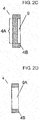
- FIG. 2C is a side sectional view of FIG. 2A or FIG. 2B .
- recess 9 is formed at a central location of one surface of end plate 4, and battery block 1 is sandwiched and fixed by the surface where recess 9 are formed in end plates 4.
- end plate 4 has thin part 4A at the central portion. Then, preferably, thin part 4A is formed such that recess 9 is provided at a surface of end plate 4 facing single battery 2.
- recess 9 is shown, but this part is not limited to be recess 9.
- through hole 9A may be provided at the central portion of end plate 4.
- this assembled battery has battery block 1 configured by stacking the plurality of single batteries 2, and fixing components fixing the plurality of single batteries 2.
- the fixing components include a pair of end plates 4 disposed at both ends in a stacked direction of the plurality of single batteries 2, and metal band 5 making the plurality of single batteries 2 in a compressed state by coupling end parts of the pair of end plates 4 each other.
- Each of the pair of end plates 4 has peripheral part 4B and central part 4C.
- the pair of end plates 4 respectively contact both end single batteries 2E located at both ends in the stacked direction of the plurality of single batteries 2 at peripheral parts 4B, and are respectively separated from both end single batteries 2E at central parts 4C.
- FIG. 3 is a schematic view of a state of battery block 1 at the time when single batteries 2 are swollen, showing a sectional view along a line 3-3 in FIG. 1 .
- the central portion of single battery 2 having a high capacity is swollen at the operating time, and separators 33 or central portions of single batteries 2 at both ends, enter into recesses 9 of end plates 4.
- the pressure which is applied to end plates 4 due to the swells at the central portions of single batteries 2 can be suppressed.
- Single battery 2 is configured by being sealed in a state where band-shaped electrodes are wound in a rectangular shape.
- the inner electrodes of single battery 2 are gradually swollen. Since the electrodes are wound so as to be bent up and down, the electrodes push single battery 2 in a rectangular shape due to the swell. Therefore, as the shapes of recess 9 or through hole 9A of end plate 4, the rectangular shape shown in FIG. 2B has a high effect, but even the circular shape shown FIG. 2A has a certain degree of an effect.
- FIG. 4 is a sectional view of a portion including recess 9b of end plate 4.
- the swell amount of single battery 2 is a minimum height of 0.03 mm, depending on the operating state of charge and discharge. In contrast, the bigger the depth of recess 9b is, the bigger the reducing effect of the pressure applied to end plate 4 is.
- the circular or rectangular through hole 9A is provided instead of recess 9b, the pressure by the swell of single batteries 2 is not received at the central portion of end plate 4.
- the depth of recess 9b is preferably 10 % or less of the thickness of a portion except recess 9b. Namely, the depth (maximum depth) of recess 9b is 0.03 mm or more, and is 10 % or less of the thickness t in the portion except thin part 4A of end plate 4.
- the opening area of recess 9 is 30 % or more, and 80 % or less than the area where end plate 4 contacts single battery 2.
- the opening area of recess 9 When single battery 2 is swollen, the area of a portion to which the pressure is applied in contact with end plate 4,is 30 % or more, and the opening area of recess 9 also need be equal to or more than this value. In contrast, when the opening area is large, an area or a region which receives the pressure by the swell of single batteries 2, becomes small. By concentrating the load to this portion, plasticity deformation or damage of end plate 4 may occur. In order to avoid this state, it is necessary that the region of 20 % or more in the area of end plate 4 receives the pressure. Namely, it is preferable that the opening area of recess 9 is 80 % or more.
- the minimum inclination angle at a time of the swell of single battery 2 is one or less degree, and the maximum inclination angle is ten or less degrees. Therefore, in order that the pressure is not received from peripheral part 4B of recess 9b at the time of the swell of single battery 2, when the inclination angle ⁇ at the periphery of recess 9b is ten or more degrees, the inclination angle does not hinder the swell.
- peripheral part 4B of end plate 4 except recess 9b contacts single battery 2.
- the area of peripheral part 4B having a length L receives the pressure from battery block 1.
- the area has a size such that binding force of metal band 5 does not cause plasticity deformation of single battery 2.
- the portion which contacts battery block 1, is adjacent to metal band 5. This prevents end plate 4 from being deformed. Since the pressures generated during the operation are different depending on the capacities of single batteries 2, the minimum value of length L cannot be determined. However, it is preferable that length L is 10 or more mm.
- end plate 4 which receives the pressure
- peripheral part 4B and peripheral part 4B is adjacent to metal bands 5 as the fixing components.
- the high hardness portion of end plate 4 receives the pressure.
- the enlargement of the whole outer size of the assembled battery can be suppressed.
- FIG. 5 is a sectional view of a portion including recess 9c of end plate 4 relating to an embodiment 2 of the present invention.
- the different point from the embodiment 1 is that the shape in the depth direction of recess 9c is a curved surface.
- FIG. 6A is a plan view of end plate 10 in an assembled battery relating to an embodiment 3 of the present invention
- FIG. 6B is a front view of end plate 10.
- the different point from the embodiment 1 is that recess 11 penetrates end plate 10 in the vertical direction and the thick portions in the plate thickness are adjacent to and fixed by metal bands 5.
- FIG. 2A, FIG. 2B when contacting potions remain at four sides in peripheral part 4B of end plate 4, practically recess 9 is formed by mechanical working.
- FIG. 6A in the case where recess 11 penetrates in the one direction, for example, a component made of aluminum can be used as extruded material.
- a component made of aluminum can be used as extruded material.
- the productivity is high, the components are inexpensive.
- the load stress becomes maximized at the adjacent or fixing portions of end plates 10 and metal bands 5. Therefore, the plate thicknesses of those portions of end plate 10 is made thick, and then the hardness is made high, and the deformation can be minimalized.
- FIG. 7A is a plan view of end plate 12 relating to an embodiment 4 of the present invention
- FIG. 7B is a side view of end plate 12.
- end plate 12 is configured of two components of end plate 13 made of aluminum and end plate 14 made of steel. End plate 13 and end plate 14 may be jointed, or coupled by a screw.
- End plate 14 made of steel is arranged at the side facing battery block 1. Since single battery 2 as a swelling source is near, this arrangement enhances the hardness. When the outer shapes are the same and end plate 14 made of steel having a higher hardness than that of aluminum is used, the hardness is enhanced, but the weight becomes heavy. However, since recess 15 is provided, the weight is reduced by eliminating a material corresponding to recess 15.
- end plates 13, 14 are not limited to aluminum and steel.
- End plate 12 is configured of two kinds of different materials, and one of the different materials has a higher hardness than that of another of the different materials, and the one of the different materials is disposed at a side contacting battery block 1.
- the assembled battery of the present invention can be used as uses of the assembled batteries of cylindrical or pouch batteries besides rectangular batteries.
Landscapes
- Chemical & Material Sciences (AREA)
- Chemical Kinetics & Catalysis (AREA)
- Electrochemistry (AREA)
- General Chemical & Material Sciences (AREA)
- Inorganic Chemistry (AREA)
- Battery Mounting, Suspending (AREA)
Abstract
Description
- The present invention relates to an assembled battery where a plurality of rectangular batteries are stacked through fixing components.
- In a conventional assembled battery, in order to prevent a decrease of battery performance, for example, a plurality of rectangular batteries are stacked and fixed (for example, refer to Patent Literature 1).
FIG. 8 is a view showing a conventional assembled battery described inPatent Literature 1. - This assembled battery has a
battery block 23 configured by stacking a plurality of rectangularsingle batteries 21, and fixingcomponents 24 fixing the plurality of thesingle batteries 21. Thefixing components 24 include a pair ofend plates 25 disposed at both end surfaces of the plurality of thesingle batteries 21, and ametal band 26 fixing the stackedsingle batteries 21 in a compressed state by coupling end parts of theend plates 25. - Patent Literature 1: Japanese Laid-Open Patent Publication No.
2008-282582 - The present invention provides an assembled battery where an enlargement of an outer size of the assembled battery is suppressed when the single batteries operate.
- An assembled battery of the present invention has a battery block configured by stacking a plurality of single batteries, and fixing components fixing the plurality of the single batteries. The fixing components include a pair of end plates disposed at both ends in a stacked direction of the plurality of the single batteries, and a metal band making the plurality of the single batteries in a compressed state by coupling end parts of the pair of the end plates each other. The pair of the end plates respectively contact both end single batteries located at both ends in the stacked direction at the peripheral parts, and are respectively separated from both end single batteries at the central parts.
- By this configuration, even though the single batteries are swollen in its thickness direction when the single batteries operate, the pressure from the plurality of the single batteries can be received by the peripheral part of the end plate. Additionally, since a part of a swell amount of the single battery is absorbed in a portion except the peripheral part of the end plate, the enlargement of the whole outer size of the assembled battery can be suppressed.
-
-
FIG. 1 is a main configuration view of an assembled battery relating to anembodiment 1 of the present invention. -
FIG. 2A is a plan view of an end plate relating to theembodiment 1 of the present invention. -
FIG. 2B is a plan view of another end plate relating to theembodiment 1 of the present invention. -
FIG. 2C is a side sectional view of the end plate shown inFIG. 2A . -
FIG. 2D is a side sectional view of the end plate shown inFIG. 2B . -
FIG. 3 is a schematic view of a state of a battery block at the time when single batteries are swollen relating to anembodiment 1 of the present invention. -
FIG. 4 is a sectional view of a portion including a recess of the end plate relating to theembodiment 1 of the present invention. -
FIG. 5 is a sectional view of a portion including a recess of an end plate relating to anembodiment 2 of the present invention. -
FIG. 6A is a plan view of an end plate relating to anembodiment 3 of the present invention. -
FIG. 6B is a front view of the end plate relating to theembodiment 3 of the present invention. -
FIG. 7A is a plan view of an end plate relating to anembodiment 4 of the present invention. -
FIG. 7B is a side view of an end plate relating to theembodiment 4 of the present invention. -
FIG. 8 is a view showing a configuration of a conventional assembled battery. - Problems in a conventional assembled battery are briefly described before an embodiment of the present invention is described. In a configuration shown in
FIG. 8 , when single batteries operate, a temperature insidesingle battery 21 increases by a chemical reaction, and it happens thatsingle batteries 21 are swollen in a thickness direction. At this time, since stackedsingle batteries 21 are bound in a compressed state, pressure by repulsion is applied toend plate 25, and then tensile force is applied tometal band 26. In the case where a capacity of the single battery is small, the pressure by repulsion is small, and then an elongation amount of the metal band does not matter. In accordance with increasing a capacity of the single battery recently, there is a tendency that the chemical reaction easily happens inside the single battery. Therefore, deformation of the end plate or the metal band becomes large, and then an outer size of the assembled battery is changed. - Embodiments of the present invention will be explained below, referring to the figures.
-
FIG. 1 is a main configuration view of an assembled battery relating to anembodiment 1 of the present invention.Battery block 1 is configured by alternatively stackingsingle batteries 2 as a plurality of rectangular batteries (rectangular parallelepiped batteries or prismatic batteries) andseparators 33. - In this assembled battery, both sides of
battery block 1 are sandwiched and fixed betweenend plates 4 as fixing components made of aluminum, andbolts 6 are fixed inscrew taps 8 ofend plates 4 throughholes 7 ofmetal bands 5 made of steel.Separators 33 may be made of resin. -
FIG. 2A and FIG. 2B are front views of theend plates 4. InFIG. 2A ,recess 9 has a circular shape, and inFIG. 2B ,recess 9 has a rectangular shape.FIG. 2C is a side sectional view ofFIG. 2A or FIG. 2B . In detail,recess 9 is formed at a central location of one surface ofend plate 4, andbattery block 1 is sandwiched and fixed by the surface whererecess 9 are formed inend plates 4. Namely,end plate 4 hasthin part 4A at the central portion. Then, preferably,thin part 4A is formed such thatrecess 9 is provided at a surface ofend plate 4 facingsingle battery 2. - Here, in
FIG. 2C , as one example,recess 9 is shown, but this part is not limited to berecess 9. For example, as shown inFIG. 2D , throughhole 9A may be provided at the central portion ofend plate 4. - Namely, this assembled battery has
battery block 1 configured by stacking the plurality ofsingle batteries 2, and fixing components fixing the plurality ofsingle batteries 2. The fixing components include a pair ofend plates 4 disposed at both ends in a stacked direction of the plurality ofsingle batteries 2, andmetal band 5 making the plurality ofsingle batteries 2 in a compressed state by coupling end parts of the pair ofend plates 4 each other. Each of the pair ofend plates 4 hasperipheral part 4B andcentral part 4C. The pair ofend plates 4 respectively contact both endsingle batteries 2E located at both ends in the stacked direction of the plurality ofsingle batteries 2 atperipheral parts 4B, and are respectively separated from both endsingle batteries 2E atcentral parts 4C. -
FIG. 3 is a schematic view of a state ofbattery block 1 at the time whensingle batteries 2 are swollen, showing a sectional view along a line 3-3 inFIG. 1 . The central portion ofsingle battery 2 having a high capacity is swollen at the operating time, andseparators 33 or central portions ofsingle batteries 2 at both ends, enter intorecesses 9 ofend plates 4. Thus, the pressure which is applied toend plates 4 due to the swells at the central portions ofsingle batteries 2, can be suppressed. -
Single battery 2 is configured by being sealed in a state where band-shaped electrodes are wound in a rectangular shape. When charge and discharge are repeated as a battery operation, the inner electrodes ofsingle battery 2 are gradually swollen. Since the electrodes are wound so as to be bent up and down, the electrodes pushsingle battery 2 in a rectangular shape due to the swell. Therefore, as the shapes ofrecess 9 or throughhole 9A ofend plate 4, the rectangular shape shown inFIG. 2B has a high effect, but even the circular shape shownFIG. 2A has a certain degree of an effect. -
FIG. 4 is a sectional view of aportion including recess 9b ofend plate 4. - The swell amount of
single battery 2 is a minimum height of 0.03 mm, depending on the operating state of charge and discharge. In contrast, the bigger the depth ofrecess 9b is, the bigger the reducing effect of the pressure applied toend plate 4 is. When the circular or rectangular throughhole 9A is provided instead ofrecess 9b, the pressure by the swell ofsingle batteries 2 is not received at the central portion ofend plate 4. - When a load to end
plate 4 is considered, throughhole 9A where the pressure is not applied to the central portion ofend plate 4, is an advantageous structure. On the other hand, the hardness ofend plate 4 having throughhole 9A becomes small, and its deformation becomes big. Therefore, the depth ofrecess 9b ofend plate 4 is determined in the appropriate range, considering a balance of the pressure reducing effect and the decrease of the hardness. - In order that the hardness of
end plate 4 is not decreased, the depth ofrecess 9b is preferably 10 % or less of the thickness of a portion exceptrecess 9b. Namely, the depth (maximum depth) ofrecess 9b is 0.03 mm or more, and is 10 % or less of the thickness t in the portion exceptthin part 4A ofend plate 4. - It is preferable that the opening area of
recess 9 is 30 % or more, and 80 % or less than the area whereend plate 4 contactssingle battery 2. - When
single battery 2 is swollen, the area of a portion to which the pressure is applied in contact withend plate 4,is 30 % or more, and the opening area ofrecess 9 also need be equal to or more than this value. In contrast, when the opening area is large, an area or a region which receives the pressure by the swell ofsingle batteries 2, becomes small. By concentrating the load to this portion, plasticity deformation or damage ofend plate 4 may occur. In order to avoid this state, it is necessary that the region of 20 % or more in the area ofend plate 4 receives the pressure. Namely, it is preferable that the opening area ofrecess 9 is 80 % or more. - The minimum inclination angle at a time of the swell of
single battery 2 is one or less degree, and the maximum inclination angle is ten or less degrees. Therefore, in order that the pressure is not received fromperipheral part 4B ofrecess 9b at the time of the swell ofsingle battery 2, when the inclination angle θ at the periphery ofrecess 9b is ten or more degrees, the inclination angle does not hinder the swell. - Assume that
recess 9b is manufactured by mechanical working, the maximum of the inclination angle is 90 degrees from the limitation of tool shapes. Further,peripheral part 4B ofend plate 4 exceptrecess 9b, contactssingle battery 2. Then, the area ofperipheral part 4B having a length L, receives the pressure frombattery block 1. The area has a size such that binding force ofmetal band 5 does not cause plasticity deformation ofsingle battery 2. The portion whichcontacts battery block 1, is adjacent tometal band 5. This preventsend plate 4 from being deformed. Since the pressures generated during the operation are different depending on the capacities ofsingle batteries 2, the minimum value of length L cannot be determined. However, it is preferable that length L is 10 or more mm. - According to the above-mentioned structure, even though the central portion of
single battery 2 is swollen during the operation and the pressure is applied toend plates 4 throughbattery block 1, sincerecesses 9 ofend plates 4 absorb the swell, the pressure applied toend plates 4 can be decreased. - The portion of
end plate 4 which receives the pressure, isperipheral part 4B, andperipheral part 4B is adjacent tometal bands 5 as the fixing components. Thus, the high hardness portion ofend plate 4 receives the pressure. As a result, the enlargement of the whole outer size of the assembled battery can be suppressed. -
FIG. 5 is a sectional view of aportion including recess 9c ofend plate 4 relating to anembodiment 2 of the present invention. In theembodiment 2, the different point from theembodiment 1 is that the shape in the depth direction ofrecess 9c is a curved surface. - Since the shape in the depth direction of
recess 9c ofend plate 4 is the curved surface, even when the vicinity of the center insingle battery 2 is swollen and contacts recess 9c ofend plate 4,the pressure load at the central portion of the outer case ofsingle battery 2 becomes equalized. Therefore, the central portion of the outer case can be prevented from being damaged. -
FIG. 6A is a plan view ofend plate 10 in an assembled battery relating to anembodiment 3 of the present invention, andFIG. 6B is a front view ofend plate 10. In theembodiment 3, the different point from theembodiment 1 is thatrecess 11 penetratesend plate 10 in the vertical direction and the thick portions in the plate thickness are adjacent to and fixed bymetal bands 5. As shown inFIG. 2A, FIG. 2B , when contacting potions remain at four sides inperipheral part 4B ofend plate 4, practicallyrecess 9 is formed by mechanical working. - In contrast, as shown in
FIG. 6A, FIG. 6B , in the case whererecess 11 penetrates in the one direction, for example, a component made of aluminum can be used as extruded material. Thus, the productivity is high, the components are inexpensive. - Here, due to the pressure generated by the swell of
single battery 2, the load stress becomes maximized at the adjacent or fixing portions ofend plates 10 andmetal bands 5. Therefore, the plate thicknesses of those portions ofend plate 10 is made thick, and then the hardness is made high, and the deformation can be minimalized. -
FIG. 7A is a plan view ofend plate 12 relating to anembodiment 4 of the present invention, andFIG. 7B is a side view ofend plate 12. In theembodiment 4, the different point from theembodiments 1 to 3 is thatend plate 12 is configured of two components ofend plate 13 made of aluminum andend plate 14 made of steel.End plate 13 andend plate 14 may be jointed, or coupled by a screw. -
End plate 14 made of steel is arranged at the side facingbattery block 1. Sincesingle battery 2 as a swelling source is near, this arrangement enhances the hardness. When the outer shapes are the same andend plate 14 made of steel having a higher hardness than that of aluminum is used, the hardness is enhanced, but the weight becomes heavy. However, sincerecess 15 is provided, the weight is reduced by eliminating a material corresponding to recess 15. - Here, materials of
end plates End plate 12 is configured of two kinds of different materials, and one of the different materials has a higher hardness than that of another of the different materials, and the one of the different materials is disposed at a side contactingbattery block 1. - The assembled battery of the present invention can be used as uses of the assembled batteries of cylindrical or pouch batteries besides rectangular batteries.
-
- 1, 23: battery block
- 2, 21: single battery
- 2E: both end single battery
- 4, 10, 12. 13, 14, 25: end plate
- 4A: thin part
- 4B: peripheral part
- 4C: central part
- 5, 26: metal band
- 6: bolt
- 7: hole
- 8: tap
- 9, 9b, 9c, 11, 15: recess
- 9A: through hole
- 33: separator
Claims (7)
- An assembled battery comprising:a battery block configured by stacking a plurality of single batteries; andfixing components fixing the plurality of the single batteries,wherein the fixing components include a pair of end plates disposed at both ends in a stacked direction of the plurality of the single batteries, and a metal band compressing the plurality of the single batteries by coupling end parts of the pair of the end plates to each other,each of the pair of the end plates has a peripheral part and a central part,
andthe pair of the end plates respectively contact both end single batteries located at both ends in the stacked direction at the peripheral parts, and are respectively separated from both end single batteries at the central parts. - The assembled battery according to claim 1,
wherein in one of the end plates, a though hole is provided at the central part. - The assembled battery according to claim 1,
wherein in one of the end plates, a thin part is provided at the central part. - The assembled battery according to claim 3,
wherein in the one of the end plates, the thin part is formed such that a recess is provided on a surface of the one of the end plates facing the plurality of the single batteries. - The assembled battery according to claim 4,
wherein a maximum depth of the recess is 0.03 mm or more, and is 10 % or less of a thickness in a portion other than the recess. - The assembled battery according to claim 1,
wherein a portion of one of the end plates contacting the battery block, is adjacent to the metal band. - The assembled battery according to claim 1,
wherein one of the end plates is configured of two kinds of different materials, and one of the different materials having a higher hardness is disposed at an inner side contacting the battery block.
Applications Claiming Priority (3)
| Application Number | Priority Date | Filing Date | Title |
|---|---|---|---|
| JP2014081658 | 2014-04-11 | ||
| JP2015033533A JP6028231B2 (en) | 2014-04-11 | 2015-02-24 | Assembled battery |
| PCT/JP2015/001940 WO2015155981A1 (en) | 2014-04-11 | 2015-04-07 | Battery pack |
Publications (3)
| Publication Number | Publication Date |
|---|---|
| EP3131137A1 true EP3131137A1 (en) | 2017-02-15 |
| EP3131137A4 EP3131137A4 (en) | 2017-02-15 |
| EP3131137B1 EP3131137B1 (en) | 2018-12-12 |
Family
ID=54287567
Family Applications (1)
| Application Number | Title | Priority Date | Filing Date |
|---|---|---|---|
| EP15776867.2A Active EP3131137B1 (en) | 2014-04-11 | 2015-04-07 | Battery pack |
Country Status (4)
| Country | Link |
|---|---|
| US (1) | US10249856B2 (en) |
| EP (1) | EP3131137B1 (en) |
| JP (1) | JP6028231B2 (en) |
| WO (1) | WO2015155981A1 (en) |
Cited By (2)
| Publication number | Priority date | Publication date | Assignee | Title |
|---|---|---|---|---|
| EP3168899B1 (en) * | 2015-11-16 | 2020-07-01 | Samsung SDI Co., Ltd. | Rechargeable battery module |
| EP4395027A1 (en) * | 2022-12-30 | 2024-07-03 | Automotive Cells Company SE | Battery module and method for assembling such a battery module |
Families Citing this family (39)
| Publication number | Priority date | Publication date | Assignee | Title |
|---|---|---|---|---|
| CN107004798B (en) | 2014-11-28 | 2020-03-03 | 三洋电机株式会社 | Battery pack and vehicle having the same |
| WO2016166972A1 (en) * | 2015-04-16 | 2016-10-20 | パナソニックIpマネジメント株式会社 | Assembled battery |
| ES2893974T3 (en) | 2016-03-03 | 2022-02-10 | Procter & Gamble | Aerosol anti-dandruff composition |
| US11154467B2 (en) | 2016-10-21 | 2021-10-26 | The Procter And Gamble Plaza | Concentrated shampoo dosage of foam designating hair conditioning benefits |
| WO2018075841A1 (en) | 2016-10-21 | 2018-04-26 | The Procter & Gamble Company | Concentrated shampoo dosage of foam for providing hair care benefits |
| MX386123B (en) | 2016-10-21 | 2025-03-18 | Procter & Gamble | COMPACT AND STABLE SHAMPOO PRODUCTS WITH LOW VISCOSITY AND VISCOSITY REDUCING AGENT. |
| US11141361B2 (en) | 2016-10-21 | 2021-10-12 | The Procter And Gamble Plaza | Concentrated shampoo dosage of foam designating hair volume benefits |
| JP7024735B2 (en) * | 2017-02-03 | 2022-02-24 | 株式会社Gsユアサ | Power storage device |
| US11679073B2 (en) | 2017-06-06 | 2023-06-20 | The Procter & Gamble Company | Hair compositions providing improved in-use wet feel |
| US11141370B2 (en) | 2017-06-06 | 2021-10-12 | The Procter And Gamble Company | Hair compositions comprising a cationic polymer mixture and providing improved in-use wet feel |
| US11224567B2 (en) | 2017-06-06 | 2022-01-18 | The Procter And Gamble Company | Hair compositions comprising a cationic polymer/silicone mixture providing improved in-use wet feel |
| CN110679002B (en) * | 2017-06-30 | 2022-04-08 | 株式会社村田制作所 | Battery |
| WO2019074988A1 (en) | 2017-10-10 | 2019-04-18 | The Procter & Gamble Company | A method of treating hair or skin with a personal care composition in a foam form |
| US11607373B2 (en) | 2017-10-10 | 2023-03-21 | The Procter & Gamble Company | Sulfate free clear personal cleansing composition comprising low inorganic salt |
| MX388495B (en) | 2017-10-10 | 2025-03-20 | Procter & Gamble | COMPACT SHAMPOO COMPOSITION CONTAINING SULFATE-FREE SURFACTANTS. |
| JP2020536876A (en) | 2017-10-10 | 2020-12-17 | ザ プロクター アンド ギャンブル カンパニーThe Procter & Gamble Company | Compact shampoo composition containing amino acid-based anionic surfactant and cationic polymer |
| JP7056142B2 (en) | 2017-12-25 | 2022-04-19 | トヨタ自動車株式会社 | Battery module |
| US11817593B2 (en) | 2018-03-30 | 2023-11-14 | Sanyo Electric Co., Ltd. | Power supply device and vehicle provided with power supply device |
| JP7033255B2 (en) * | 2018-05-02 | 2022-03-10 | トヨタ自動車株式会社 | Batteries assembled |
| MX2020014144A (en) | 2018-06-29 | 2021-03-25 | Procter & Gamble | ANTI-DANDRUFF COMPOSITION IN AEROSOL WITH LOW SURFACTANT CONTENT. |
| US12226505B2 (en) | 2018-10-25 | 2025-02-18 | The Procter & Gamble Company | Compositions having enhanced deposition of surfactant-soluble anti-dandruff agents |
| JP7298204B2 (en) * | 2019-03-11 | 2023-06-27 | 株式会社Gsユアサ | power storage device |
| JP7410298B2 (en) | 2019-12-06 | 2024-01-09 | ザ プロクター アンド ギャンブル カンパニー | Sulfate-free composition that strengthens the adhesion of scalp active substances |
| MX2022009191A (en) | 2020-02-27 | 2022-08-18 | Procter & Gamble | ANTI-DANDRUFF COMPOSITIONS WITH SULFUR THAT HAVE IMPROVED EFFICACY AND AESTHETICS. |
| CN212392341U (en) * | 2020-06-09 | 2021-01-22 | 比亚迪股份有限公司 | Battery packs and vehicles |
| CN212659640U (en) | 2020-07-28 | 2021-03-05 | 厦门海辰新能源科技有限公司 | Battery module fixing assembly and battery pack |
| CN111969144A (en) * | 2020-08-19 | 2020-11-20 | 刘培君 | Efficient new energy lithium battery and preparation process thereof |
| JP7167103B2 (en) * | 2020-08-25 | 2022-11-08 | プライムプラネットエナジー&ソリューションズ株式会社 | Power storage device and manufacturing method thereof |
| JP7241052B2 (en) * | 2020-09-11 | 2023-03-16 | 本田技研工業株式会社 | Cell storage body, power storage module and vehicle |
| WO2022065841A1 (en) * | 2020-09-22 | 2022-03-31 | 주식회사 엘지에너지솔루션 | Battery module, battery pack comprising same, and vehicle |
| KR102951000B1 (en) | 2020-11-23 | 2026-04-10 | 주식회사 엘지에너지솔루션 | Battery Pack Including Heat Diffusion Suppression Structure |
| JP7678101B2 (en) | 2020-11-23 | 2025-05-15 | ザ プロクター アンド ギャンブル カンパニー | Personal care compositions free of sulfated surfactants |
| US11819474B2 (en) | 2020-12-04 | 2023-11-21 | The Procter & Gamble Company | Hair care compositions comprising malodor reduction materials |
| US12409125B2 (en) | 2021-05-14 | 2025-09-09 | The Procter & Gamble Company | Shampoo compositions containing a sulfate-free surfactant system and sclerotium gum thickener |
| US11986543B2 (en) | 2021-06-01 | 2024-05-21 | The Procter & Gamble Company | Rinse-off compositions with a surfactant system that is substantially free of sulfate-based surfactants |
| JP7809941B2 (en) * | 2021-10-01 | 2026-02-03 | 株式会社Gsユアサ | Power storage device |
| JP2024544222A (en) | 2021-12-09 | 2024-11-28 | ザ プロクター アンド ギャンブル カンパニー | Sulfate-free personal cleansing composition with effective preservative properties - Patents.com |
| CN115360464B (en) * | 2022-09-19 | 2024-03-08 | 厦门海辰储能科技股份有限公司 | End plate and energy storage device |
| CN118156707A (en) * | 2022-11-30 | 2024-06-07 | 北京车和家汽车科技有限公司 | Battery modules, battery packs and vehicles |
Family Cites Families (7)
| Publication number | Priority date | Publication date | Assignee | Title |
|---|---|---|---|---|
| JP3271494B2 (en) * | 1995-10-24 | 2002-04-02 | 松下電器産業株式会社 | Stacked sealed alkaline storage battery |
| JP2008282582A (en) | 2007-05-08 | 2008-11-20 | Sanyo Electric Co Ltd | Assembled battery |
| US8865331B2 (en) * | 2010-06-16 | 2014-10-21 | Toyota Jidosha Kabushiki Kaisha | Secondary battery assembly |
| DE102011076575A1 (en) * | 2011-05-27 | 2012-11-29 | Bmw Ag | Energy storage module of several, in particular prismatic memory cells and method for producing an energy storage module and method for producing an end plate for an energy storage module |
| KR101255250B1 (en) * | 2012-03-23 | 2013-04-16 | 삼성에스디아이 주식회사 | Battery module |
| JP2015111493A (en) * | 2012-03-28 | 2015-06-18 | 三洋電機株式会社 | Power supply device, and vehicle and power storage device comprising the same |
| JP6073583B2 (en) * | 2012-06-28 | 2017-02-01 | 三洋電機株式会社 | Power supply device, vehicle including this power supply device, and power storage device |
-
2015
- 2015-02-24 JP JP2015033533A patent/JP6028231B2/en active Active
- 2015-04-07 EP EP15776867.2A patent/EP3131137B1/en active Active
- 2015-04-07 WO PCT/JP2015/001940 patent/WO2015155981A1/en not_active Ceased
- 2015-04-07 US US15/128,929 patent/US10249856B2/en active Active
Cited By (2)
| Publication number | Priority date | Publication date | Assignee | Title |
|---|---|---|---|---|
| EP3168899B1 (en) * | 2015-11-16 | 2020-07-01 | Samsung SDI Co., Ltd. | Rechargeable battery module |
| EP4395027A1 (en) * | 2022-12-30 | 2024-07-03 | Automotive Cells Company SE | Battery module and method for assembling such a battery module |
Also Published As
| Publication number | Publication date |
|---|---|
| EP3131137A4 (en) | 2017-02-15 |
| EP3131137B1 (en) | 2018-12-12 |
| JP6028231B2 (en) | 2016-11-16 |
| JP2015207553A (en) | 2015-11-19 |
| WO2015155981A1 (en) | 2015-10-15 |
| US10249856B2 (en) | 2019-04-02 |
| US20170110695A1 (en) | 2017-04-20 |
Similar Documents
| Publication | Publication Date | Title |
|---|---|---|
| EP3131137B1 (en) | Battery pack | |
| EP2988346B1 (en) | Cell case | |
| EP3223333A1 (en) | Rechargeable battery | |
| US11088388B2 (en) | Clamping member and battery module using the same | |
| EP3285310B1 (en) | Assembled battery | |
| US9954209B2 (en) | Battery pack | |
| EP3796417B1 (en) | Secondary battery and battery pack including the same | |
| EP2804235B1 (en) | Secondary battery | |
| EP3883033A1 (en) | Secondary battery and battery module | |
| EP3800696B1 (en) | Secondary battery, battery module and electric vehicle | |
| US20180175437A1 (en) | Battery | |
| EP2605310B1 (en) | Secondary battery module | |
| US12555876B2 (en) | Current blocking structure applied to pouch type secondary battery | |
| JP2016081867A (en) | Structure for explosion-proof valve for container | |
| KR102119704B1 (en) | Top cap and cap assembly for secondary battery including the same | |
| WO2020059299A1 (en) | Battery module | |
| US12009534B2 (en) | Secondary battery | |
| JP7256163B2 (en) | battery module | |
| EP4530492A1 (en) | Cushioning sheet | |
| US20230061623A1 (en) | Power storage device | |
| US20230041356A1 (en) | Battery | |
| EP4068319A1 (en) | Power storage module | |
| JP2018063884A (en) | Battery pack |
Legal Events
| Date | Code | Title | Description |
|---|---|---|---|
| STAA | Information on the status of an ep patent application or granted ep patent |
Free format text: STATUS: THE INTERNATIONAL PUBLICATION HAS BEEN MADE |
|
| PUAI | Public reference made under article 153(3) epc to a published international application that has entered the european phase |
Free format text: ORIGINAL CODE: 0009012 |
|
| STAA | Information on the status of an ep patent application or granted ep patent |
Free format text: STATUS: REQUEST FOR EXAMINATION WAS MADE |
|
| 17P | Request for examination filed |
Effective date: 20160929 |
|
| A4 | Supplementary search report drawn up and despatched |
Effective date: 20170102 |
|
| AK | Designated contracting states |
Kind code of ref document: A1 Designated state(s): AL AT BE BG CH CY CZ DE DK EE ES FI FR GB GR HR HU IE IS IT LI LT LU LV MC MK MT NL NO PL PT RO RS SE SI SK SM TR |
|
| AX | Request for extension of the european patent |
Extension state: BA ME |
|
| DAV | Request for validation of the european patent (deleted) | ||
| DAX | Request for extension of the european patent (deleted) | ||
| GRAP | Despatch of communication of intention to grant a patent |
Free format text: ORIGINAL CODE: EPIDOSNIGR1 |
|
| STAA | Information on the status of an ep patent application or granted ep patent |
Free format text: STATUS: GRANT OF PATENT IS INTENDED |
|
| INTG | Intention to grant announced |
Effective date: 20180625 |
|
| GRAS | Grant fee paid |
Free format text: ORIGINAL CODE: EPIDOSNIGR3 |
|
| GRAA | (expected) grant |
Free format text: ORIGINAL CODE: 0009210 |
|
| STAA | Information on the status of an ep patent application or granted ep patent |
Free format text: STATUS: THE PATENT HAS BEEN GRANTED |
|
| AK | Designated contracting states |
Kind code of ref document: B1 Designated state(s): AL AT BE BG CH CY CZ DE DK EE ES FI FR GB GR HR HU IE IS IT LI LT LU LV MC MK MT NL NO PL PT RO RS SE SI SK SM TR |
|
| REG | Reference to a national code |
Ref country code: GB Ref legal event code: FG4D |
|
| REG | Reference to a national code |
Ref country code: CH Ref legal event code: EP |
|
| REG | Reference to a national code |
Ref country code: AT Ref legal event code: REF Ref document number: 1077162 Country of ref document: AT Kind code of ref document: T Effective date: 20181215 |
|
| REG | Reference to a national code |
Ref country code: DE Ref legal event code: R096 Ref document number: 602015021477 Country of ref document: DE |
|
| REG | Reference to a national code |
Ref country code: IE Ref legal event code: FG4D |
|
| REG | Reference to a national code |
Ref country code: NL Ref legal event code: MP Effective date: 20181212 |
|
| REG | Reference to a national code |
Ref country code: LT Ref legal event code: MG4D |
|
| PG25 | Lapsed in a contracting state [announced via postgrant information from national office to epo] |
Ref country code: ES Free format text: LAPSE BECAUSE OF FAILURE TO SUBMIT A TRANSLATION OF THE DESCRIPTION OR TO PAY THE FEE WITHIN THE PRESCRIBED TIME-LIMIT Effective date: 20181212 Ref country code: LT Free format text: LAPSE BECAUSE OF FAILURE TO SUBMIT A TRANSLATION OF THE DESCRIPTION OR TO PAY THE FEE WITHIN THE PRESCRIBED TIME-LIMIT Effective date: 20181212 Ref country code: NO Free format text: LAPSE BECAUSE OF FAILURE TO SUBMIT A TRANSLATION OF THE DESCRIPTION OR TO PAY THE FEE WITHIN THE PRESCRIBED TIME-LIMIT Effective date: 20190312 Ref country code: FI Free format text: LAPSE BECAUSE OF FAILURE TO SUBMIT A TRANSLATION OF THE DESCRIPTION OR TO PAY THE FEE WITHIN THE PRESCRIBED TIME-LIMIT Effective date: 20181212 Ref country code: BG Free format text: LAPSE BECAUSE OF FAILURE TO SUBMIT A TRANSLATION OF THE DESCRIPTION OR TO PAY THE FEE WITHIN THE PRESCRIBED TIME-LIMIT Effective date: 20190312 Ref country code: HR Free format text: LAPSE BECAUSE OF FAILURE TO SUBMIT A TRANSLATION OF THE DESCRIPTION OR TO PAY THE FEE WITHIN THE PRESCRIBED TIME-LIMIT Effective date: 20181212 Ref country code: LV Free format text: LAPSE BECAUSE OF FAILURE TO SUBMIT A TRANSLATION OF THE DESCRIPTION OR TO PAY THE FEE WITHIN THE PRESCRIBED TIME-LIMIT Effective date: 20181212 |
|
| REG | Reference to a national code |
Ref country code: AT Ref legal event code: MK05 Ref document number: 1077162 Country of ref document: AT Kind code of ref document: T Effective date: 20181212 |
|
| PG25 | Lapsed in a contracting state [announced via postgrant information from national office to epo] |
Ref country code: RS Free format text: LAPSE BECAUSE OF FAILURE TO SUBMIT A TRANSLATION OF THE DESCRIPTION OR TO PAY THE FEE WITHIN THE PRESCRIBED TIME-LIMIT Effective date: 20181212 Ref country code: AL Free format text: LAPSE BECAUSE OF FAILURE TO SUBMIT A TRANSLATION OF THE DESCRIPTION OR TO PAY THE FEE WITHIN THE PRESCRIBED TIME-LIMIT Effective date: 20181212 Ref country code: SE Free format text: LAPSE BECAUSE OF FAILURE TO SUBMIT A TRANSLATION OF THE DESCRIPTION OR TO PAY THE FEE WITHIN THE PRESCRIBED TIME-LIMIT Effective date: 20181212 Ref country code: GR Free format text: LAPSE BECAUSE OF FAILURE TO SUBMIT A TRANSLATION OF THE DESCRIPTION OR TO PAY THE FEE WITHIN THE PRESCRIBED TIME-LIMIT Effective date: 20190313 |
|
| PG25 | Lapsed in a contracting state [announced via postgrant information from national office to epo] |
Ref country code: NL Free format text: LAPSE BECAUSE OF FAILURE TO SUBMIT A TRANSLATION OF THE DESCRIPTION OR TO PAY THE FEE WITHIN THE PRESCRIBED TIME-LIMIT Effective date: 20181212 |
|
| PG25 | Lapsed in a contracting state [announced via postgrant information from national office to epo] |
Ref country code: IT Free format text: LAPSE BECAUSE OF FAILURE TO SUBMIT A TRANSLATION OF THE DESCRIPTION OR TO PAY THE FEE WITHIN THE PRESCRIBED TIME-LIMIT Effective date: 20181212 Ref country code: PL Free format text: LAPSE BECAUSE OF FAILURE TO SUBMIT A TRANSLATION OF THE DESCRIPTION OR TO PAY THE FEE WITHIN THE PRESCRIBED TIME-LIMIT Effective date: 20181212 Ref country code: CZ Free format text: LAPSE BECAUSE OF FAILURE TO SUBMIT A TRANSLATION OF THE DESCRIPTION OR TO PAY THE FEE WITHIN THE PRESCRIBED TIME-LIMIT Effective date: 20181212 Ref country code: PT Free format text: LAPSE BECAUSE OF FAILURE TO SUBMIT A TRANSLATION OF THE DESCRIPTION OR TO PAY THE FEE WITHIN THE PRESCRIBED TIME-LIMIT Effective date: 20190412 |
|
| PG25 | Lapsed in a contracting state [announced via postgrant information from national office to epo] |
Ref country code: SK Free format text: LAPSE BECAUSE OF FAILURE TO SUBMIT A TRANSLATION OF THE DESCRIPTION OR TO PAY THE FEE WITHIN THE PRESCRIBED TIME-LIMIT Effective date: 20181212 Ref country code: SM Free format text: LAPSE BECAUSE OF FAILURE TO SUBMIT A TRANSLATION OF THE DESCRIPTION OR TO PAY THE FEE WITHIN THE PRESCRIBED TIME-LIMIT Effective date: 20181212 Ref country code: EE Free format text: LAPSE BECAUSE OF FAILURE TO SUBMIT A TRANSLATION OF THE DESCRIPTION OR TO PAY THE FEE WITHIN THE PRESCRIBED TIME-LIMIT Effective date: 20181212 Ref country code: IS Free format text: LAPSE BECAUSE OF FAILURE TO SUBMIT A TRANSLATION OF THE DESCRIPTION OR TO PAY THE FEE WITHIN THE PRESCRIBED TIME-LIMIT Effective date: 20190412 Ref country code: RO Free format text: LAPSE BECAUSE OF FAILURE TO SUBMIT A TRANSLATION OF THE DESCRIPTION OR TO PAY THE FEE WITHIN THE PRESCRIBED TIME-LIMIT Effective date: 20181212 |
|
| REG | Reference to a national code |
Ref country code: DE Ref legal event code: R097 Ref document number: 602015021477 Country of ref document: DE |
|
| PLBE | No opposition filed within time limit |
Free format text: ORIGINAL CODE: 0009261 |
|
| STAA | Information on the status of an ep patent application or granted ep patent |
Free format text: STATUS: NO OPPOSITION FILED WITHIN TIME LIMIT |
|
| PG25 | Lapsed in a contracting state [announced via postgrant information from national office to epo] |
Ref country code: SI Free format text: LAPSE BECAUSE OF FAILURE TO SUBMIT A TRANSLATION OF THE DESCRIPTION OR TO PAY THE FEE WITHIN THE PRESCRIBED TIME-LIMIT Effective date: 20181212 Ref country code: DK Free format text: LAPSE BECAUSE OF FAILURE TO SUBMIT A TRANSLATION OF THE DESCRIPTION OR TO PAY THE FEE WITHIN THE PRESCRIBED TIME-LIMIT Effective date: 20181212 Ref country code: AT Free format text: LAPSE BECAUSE OF FAILURE TO SUBMIT A TRANSLATION OF THE DESCRIPTION OR TO PAY THE FEE WITHIN THE PRESCRIBED TIME-LIMIT Effective date: 20181212 |
|
| 26N | No opposition filed |
Effective date: 20190913 |
|
| REG | Reference to a national code |
Ref country code: CH Ref legal event code: PL |
|
| REG | Reference to a national code |
Ref country code: BE Ref legal event code: MM Effective date: 20190430 |
|
| PG25 | Lapsed in a contracting state [announced via postgrant information from national office to epo] |
Ref country code: LU Free format text: LAPSE BECAUSE OF NON-PAYMENT OF DUE FEES Effective date: 20190407 Ref country code: MC Free format text: LAPSE BECAUSE OF FAILURE TO SUBMIT A TRANSLATION OF THE DESCRIPTION OR TO PAY THE FEE WITHIN THE PRESCRIBED TIME-LIMIT Effective date: 20181212 |
|
| PG25 | Lapsed in a contracting state [announced via postgrant information from national office to epo] |
Ref country code: CH Free format text: LAPSE BECAUSE OF NON-PAYMENT OF DUE FEES Effective date: 20190430 Ref country code: LI Free format text: LAPSE BECAUSE OF NON-PAYMENT OF DUE FEES Effective date: 20190430 |
|
| PG25 | Lapsed in a contracting state [announced via postgrant information from national office to epo] |
Ref country code: BE Free format text: LAPSE BECAUSE OF NON-PAYMENT OF DUE FEES Effective date: 20190430 |
|
| PG25 | Lapsed in a contracting state [announced via postgrant information from national office to epo] |
Ref country code: TR Free format text: LAPSE BECAUSE OF FAILURE TO SUBMIT A TRANSLATION OF THE DESCRIPTION OR TO PAY THE FEE WITHIN THE PRESCRIBED TIME-LIMIT Effective date: 20181212 |
|
| PG25 | Lapsed in a contracting state [announced via postgrant information from national office to epo] |
Ref country code: IE Free format text: LAPSE BECAUSE OF NON-PAYMENT OF DUE FEES Effective date: 20190407 |
|
| REG | Reference to a national code |
Ref country code: DE Ref legal event code: R079 Ref document number: 602015021477 Country of ref document: DE Free format text: PREVIOUS MAIN CLASS: H01M0002100000 Ipc: H01M0050200000 |
|
| PG25 | Lapsed in a contracting state [announced via postgrant information from national office to epo] |
Ref country code: CY Free format text: LAPSE BECAUSE OF FAILURE TO SUBMIT A TRANSLATION OF THE DESCRIPTION OR TO PAY THE FEE WITHIN THE PRESCRIBED TIME-LIMIT Effective date: 20181212 |
|
| PG25 | Lapsed in a contracting state [announced via postgrant information from national office to epo] |
Ref country code: MT Free format text: LAPSE BECAUSE OF FAILURE TO SUBMIT A TRANSLATION OF THE DESCRIPTION OR TO PAY THE FEE WITHIN THE PRESCRIBED TIME-LIMIT Effective date: 20181212 Ref country code: HU Free format text: LAPSE BECAUSE OF FAILURE TO SUBMIT A TRANSLATION OF THE DESCRIPTION OR TO PAY THE FEE WITHIN THE PRESCRIBED TIME-LIMIT; INVALID AB INITIO Effective date: 20150407 |
|
| PG25 | Lapsed in a contracting state [announced via postgrant information from national office to epo] |
Ref country code: MK Free format text: LAPSE BECAUSE OF FAILURE TO SUBMIT A TRANSLATION OF THE DESCRIPTION OR TO PAY THE FEE WITHIN THE PRESCRIBED TIME-LIMIT Effective date: 20181212 |
|
| PGFP | Annual fee paid to national office [announced via postgrant information from national office to epo] |
Ref country code: DE Payment date: 20250422 Year of fee payment: 11 |
|
| PGFP | Annual fee paid to national office [announced via postgrant information from national office to epo] |
Ref country code: GB Payment date: 20250423 Year of fee payment: 11 |
|
| PGFP | Annual fee paid to national office [announced via postgrant information from national office to epo] |
Ref country code: FR Payment date: 20250425 Year of fee payment: 11 |