EP3131104B1 - Cooling of a static electric induction system - Google Patents
Cooling of a static electric induction system Download PDFInfo
- Publication number
- EP3131104B1 EP3131104B1 EP15181124.7A EP15181124A EP3131104B1 EP 3131104 B1 EP3131104 B1 EP 3131104B1 EP 15181124 A EP15181124 A EP 15181124A EP 3131104 B1 EP3131104 B1 EP 3131104B1
- Authority
- EP
- European Patent Office
- Prior art keywords
- cooling
- flow rate
- electric induction
- induction system
- static electric
- Prior art date
- Legal status (The legal status is an assumption and is not a legal conclusion. Google has not performed a legal analysis and makes no representation as to the accuracy of the status listed.)
- Active
Links
Images


Classifications
-
- H—ELECTRICITY
- H01—ELECTRIC ELEMENTS
- H01F—MAGNETS; INDUCTANCES; TRANSFORMERS; SELECTION OF MATERIALS FOR THEIR MAGNETIC PROPERTIES
- H01F27/00—Details of transformers or inductances, in general
- H01F27/08—Cooling; Ventilating
-
- H—ELECTRICITY
- H01—ELECTRIC ELEMENTS
- H01F—MAGNETS; INDUCTANCES; TRANSFORMERS; SELECTION OF MATERIALS FOR THEIR MAGNETIC PROPERTIES
- H01F27/00—Details of transformers or inductances, in general
- H01F27/08—Cooling; Ventilating
- H01F27/10—Liquid cooling
-
- H—ELECTRICITY
- H01—ELECTRIC ELEMENTS
- H01F—MAGNETS; INDUCTANCES; TRANSFORMERS; SELECTION OF MATERIALS FOR THEIR MAGNETIC PROPERTIES
- H01F27/00—Details of transformers or inductances, in general
- H01F27/08—Cooling; Ventilating
- H01F27/085—Cooling by ambient air
-
- H—ELECTRICITY
- H01—ELECTRIC ELEMENTS
- H01F—MAGNETS; INDUCTANCES; TRANSFORMERS; SELECTION OF MATERIALS FOR THEIR MAGNETIC PROPERTIES
- H01F27/00—Details of transformers or inductances, in general
- H01F27/08—Cooling; Ventilating
- H01F27/10—Liquid cooling
- H01F27/12—Oil cooling
-
- H—ELECTRICITY
- H01—ELECTRIC ELEMENTS
- H01F—MAGNETS; INDUCTANCES; TRANSFORMERS; SELECTION OF MATERIALS FOR THEIR MAGNETIC PROPERTIES
- H01F27/00—Details of transformers or inductances, in general
- H01F27/28—Coils; Windings; Conductive connections
- H01F27/2876—Cooling
Definitions
- the present disclosure relates to a static electric induction system comprising a heat generating component and a cooling fluid.
- JP 2006/032651 discloses the use of an insulating medium circulation flow rate increasing means which is able to temporarily increase the flow rate of the insulating/cooling medium above a steady-state flow rate upon detection of a temperature increase in the insulating medium in an electrical apparatus with an iron core and winding.
- Document US 2 917 701 discloses a liquid filled transformer having a pump for circulating the cooling fluid in which, the pump is started when the oil temperature rises and stopped when the temperature drops.
- Document US 2 479 373 discloses a liquid filled transformer having cooling ducts, a pump for circulation of the cooling liquid through a heat exchanger and a by-pass conduit with a second pump.
- the flow rate of the first pump is different than the one of the second pump.
- the heat flows slowly in the conductor winding of a static electric induction system and is often very quickly transported by the cooling fluid. This implies that the heat may not have to be convected so quickly since it is generated in a slower process. Also, it has been noted that hotspots may be formed, e.g. due to static swirls or locally stagnant fluid, also at increased flow rate of the cooling fluid. Thus, to merely increase the flow rate may not eliminate hotspots or at all (or only to a limited degree) improve the cooling of the static electric induction system.
- the cooling is improved by varying the cooling fluid flow rate over time along a predetermined flow rate curve.
- That the curve is predetermined implies that it is not dependent on real-time measurements e.g. of fluid temperature. Rather, the flow rate curve may be a function of only time. However, that the curve is predetermined may not preclude that a temperature measurement may also be allowed to affect the flow rate.
- a control unit of the static electric induction system may be pre-programmed with a plurality of predetermined flow rate curves wherein the choice of which one to use may be based on e.g. a temperature measurement or other measurement.
- a static electric induction system comprising a heat generating component, cooling fluid, a cooling duct along the heat generating component, and a pumping system configured for driving the cooling fluid through the cooling duct, wherein the pumping system is configured for applying a varying flow rate of the cooling fluid in the cooling duct along a predetermined flow rate curve.
- a method of reducing hot spots in a static electric induction system comprises cooling a heat generating component of the static electric induction system by means of a flow of cooling fluid through a cooling duct along the heat generating component.
- the method also comprises applying a varying flow rate of the flow of cooling fluid in the cooling duct along a predetermined flow rate curve by means of a pumping system of the static electric induction system.
- the cooling fluid may choose slightly different paths within the cooling duct, and positions of stagnant swirls or stagnant fluid or the like may move depending on the flow rate, thereby reducing the build-up of hotspots.
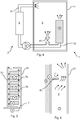
- FIG. 1 schematically illustrates an embodiment of a static electric induction system 1, here in the form of a power transformer with a transformer tank 11 which is filled with a cooling fluid 3, e.g. a mineral oil, an ester liquid or other electrically insulating liquid, or an electrically insulating gas.
- a cooling fluid e.g. a mineral oil, an ester liquid or other electrically insulating liquid, or an electrically insulating gas.
- a transformer is used as an example, but the static electric induction system 1 of the present invention may alternatively be e.g. a reactor.
- the transformer in figure 1 is a single-phase transformer, but the discussion is in applicable parts relevant for any type of transformer or other static electric induction system 1 e.g. a three-phase transformer such as with a three or five legged core. It is noted that the figure is only schematic and provided to illustrate some basic parts of the static electric induction system.
- Two neighbouring windings 4 (a & b) are shown, each comprising a coil of an electrical conductor around a core 5, e.g. a metal core.
- a core 5 e.g. a metal core.
- the static electric induction system 1 is fluid-filled with a cooling fluid 3 for improved heat transport away from heat generating components of the static electric induction system, such as the winding(s) 4 and core(s) 5 thereof.
- the fluid 3 may e.g. be mineral oil, silicon oil, synthetic ester or natural ester, or a gas (e.g. in a dry transformer).
- an ester oil e.g. a natural or synthetic ester oil.
- the conductors of the windings 4 are insulated from each other and from other parts of the transformer 1 by means of the cooling fluid.
- solid insulators 31 may be used to structurally keep the conductors and other parts of the static electric induction system 1 immobile in their intended positions.
- Such solid phase insulators are typically made of cellulose based pressboard or NomexTM impregnated by the cooling fluid 3, but any other solid insulating material may be used.
- the insulators may e.g. be in the form of spacers separating turns or discs of a winding 4 from each other, axial sticks e.g.
- winding tables separating the windings from other parts of the static electric induction system 1 e.g. forming a support or table on which the windings, cores, yokes etc. rest, as well as cylinders positioned around a winding 4, between the a winding 4 and its core 5, or between different windings 4 or different conductor layers of a winding 4.
- a cooling duct 7 may e.g. be formed along a winding 4 (generally in its longitudinal direction) between an outer solid insulation cylinder positioned outside of the winding 4, and an inner solid insulation cylinder positioned inside the said winding, between the winding and the core 5 (i.e. the inner cylinder would be around the core, the winding would be around the inner cylinder, and the outer cylinder would be around the winding).
- a winding 4 generally in its longitudinal direction
- an inner solid insulation cylinder positioned inside the said winding, between the winding and the core 5 (i.e. the inner cylinder would be around the core, the winding would be around the inner cylinder, and the outer cylinder would be around the winding).
- this is merely an example and any other form of cooling duct 7 along a heat generating component such as a winding 4 and/or core 5 may also be envisioned.
- Cooling fluid 3 may flow (be driven by the pumping system 2) in any direction through a cooling duct7, but it may be convenient to drive the cooling fluid in a generally upward direction since the pumping system will then cooperate with the passive heat convection of the fluid whereby warmer fluid has a lower density and thus rises.
- the static electric induction system 1 also comprises a pumping system 2 configured for driving the cooling fluid through the cooling duct(s) 7.
- the pumping system 2 comprises piping to form a cooling loop 10 for circulating the cooling fluid 3.
- the cooling fluid may be pumped from a cooling fluid source without being circulated and reused.
- the pumping system typically comprises a pump 9, which may be controlled by a control unit 8.
- the control unit 8 may control the pump 9 and thus the flow rate of the fluid 3 through the cooling duct 7.
- the flow rate of the fluid 3 through the cooling duct 7 may be controlled by means of a valve 41 (see figure 4 ).
- the control unit 8 may be pre-programmed with the predetermined flow rate curve in accordance with the present invention.
- the control unit 8, e.g. with input from fibre optic sensors in the winding 4 may be configured for altering the mass flow rate along the predetermined flow rate curve depending on a current temperature distribution of the static electric induction system.
- the predetermined flow rate curve may be shifted (e.g. parallel displaced) towards a higher or lower flow rate depending on a temperature measurement, or one predetermined flow rate curve may be chosen (e.g. by the control unit 8) from among a plurality of predetermined flow rate curves.
- the pumping system may comprise a heat exchanger 6 in which cooling fluid from inside of the tank 11 is cooled, e.g. by means of a (for instance counter current) flow of conventional coolant such as water or air.
- the pumping system is configured for applying a varying flow rate of the cooling fluid in the cooling duct along a predetermined flow rate curve.
- the cooling may be intermittent, the flow rate oscillating between fast and slow modes. This can be performed by providing a variable flow rate of the cooling fluid by means of the pumping system.
- the focus may mainly be on the transfer of the heat from the conductor to the fluid, i.e. it is as if the fluid 3 waits for the heat to come in. This organizes the transport of the heat in batches, filled during the low flow rate and evacuated during the high flow rate.
- the low and high flow rate levels and the corresponding time scales may be chosen by use of an appropriate optimization technique.
- layer windings with baffles 61 may be used. Cooling fluid flow in a typical winding 4 may be laminar, which implies less efficient heat transfer. By introducing baffles in combination with a varying flow rate, the heat transfer coefficient may be improved to the level of turbulent heat transfer.
- the typical cooling fluid flow distribution through alternative flow paths in a cooling duct 7 may differ depending on the mass flow rate because the balance of pressure drop and buoyancy in the system will vary.
- a first example concerns windings 4 without oil guides. In this type of winding, the location of a hotspot may depend on the mass flow rate. By varying the mass flow rate, the location of the hotspot may be shifted, reducing time-averaged temperatures of said hotspot and thereby reducing ageing and increasing the lifetime of the static electric induction system 1.
- a second example concerns windings with oil guides, e.g. blocking some flow paths in a duct 7. By varying the mass flow rate, the location of the hotspot may be shifted, reducing time-averaged temperatures of said hotspot.
- FIG. 2 illustrates an embodiment of a static electric induction system 1 in which a cooling duct 7 is formed through a heat generating component, e.g. a conductor winding 4.
- a pump 9 of the pumping system 2 drives cooling fluid 3 through the cooling duct.
- the pump 9 is arranged to pump the fluid 3 directly into the cooling duct 7, and the cooling fluid may be an ambient gas such as air, whereby the use of a tank 11 is optional and the fluid need not be recycled.
- FIG 3 illustrates another embodiment of a static electric induction system 1 in which a cooling duct 7 is formed comprising parallel flow paths 7a and 7b on either side of a heat generating component, e.g. a core 5. That the flow paths are parallel is herein not intended to imply that they are necessarily geometrically parallel, but rather that they are connected in parallel to each other as opposed to in series with each other.
- the cooling duct comprising the plurality of flow paths 7a and 7b, is formed between the heat generating component and a solid barrier 31, typically of a solid insulation material.
- a tank 11 is used, with the pumping system 2 comprising the pump 9 positioned inside the tank 11, allowing the cooling fluid 3 to be circulated in a closed system within the tank 11.
- the pumping system 2 comprising the pump 9 positioned inside the tank 11, allowing the cooling fluid 3 to be circulated in a closed system within the tank 11.
- this does not preclude that inlet(s) and outlet(s) of the tank 11 for the fluid 3 through a wall of the tank
- FIG 4 illustrates another embodiment of a static electric induction system 1 in which piping forming a cooling loop 10 for circulating the cooling fluid 3 within the static electric induction system is used.
- the cooling loop 10 of the pumping system 2 comprises the pump 9 as well as a heat exchanger 6, and extends outside of the tank 11, sucking in cooling fluid into an outlet of the tank at the top of said tank and driving cooling fluid into a cooling duct (not shown) through a heat generating component 4.
- the piping of the cooling loop 10 comprises a valve 41 inside the tank 11. The valve 41 is arranged for regulating how much of the cooling fluid 3 which passes through the heat exchanger and the pump is driven into cooling duct along the heat generating component 4.
- all the cooling fluid from the pump may be introduced into the cooling duct, while the more open the valve is, the lower ratio of the cooling fluid from the pump is introduced into the cooling duct and the higher ratio of the cooling fluid from the pump is introduced outside of the cooling duct, e.g. into a bulk of the cooling fluid or into another cooling duct 7 (not shown) in the tank 11, bypassing the cooling duct 7. It may be advantageous to maintain a substantially constant flow rate of the cooling fluid 3 through the heat exchanger 6 and/or the pump 9 since the heat exchanger 6 and/or the pump 9 may be optimised for a certain flow rate or flow rate range.
- the varying flow rate in the cooling duct may thus be achieved by controlling the valve 41 instead of (or in addition to) the pump 9.
- the valve 41 may be controlled by the control unit 8, which may or may not also control the pump speed of the pump 9.
- the cooling fluid 3 is circulated in the static electric induction system 1 via a cooling loop 10 comprising a heat exchanger 6, wherein the flow rate of the cooling fluid through the heat exchanger is substantially constant.
- Figure 5 illustrates an embodiment of a cooling duct 7 along a part of a heat generating component in the form of a conductor winding 4, where a plurality of turns of the winding 4 are separated (e.g. by spacers) in a vertical direction to form a plurality of parallel horizontal flow paths 7a and 7b (of which only two are provided with reference signs in the figure) of the cooling duct 7.
- the cooling fluid 3 is driven through the cooling duct 7, generally vertically upward but via any of the plurality of generally horizontal flow paths 7a and 7b between the winding turns.
- the ratio of the mass flow of the cooling fluid 3 in the cooling duct 7 which passes through a certain flow path 7a or 7b varies depending on the total mass flow rate through the cooling duct.
- a higher ratio of the mass flow may pass through the flow path 7a than through the flow path 7b, leading to the build-up of a hotspot x at the flow path 7b, while at a second flow rate through the cooling duct, a higher ratio of the mass flow may pass through the flow path 7b than through the flow path 7a, leading instead to the build-up of a hotspot y at the flow path 7a.
- Figure 6 illustrates a flow of cooling fluid 3 in a cooling duct 7 along a heat generating component, e.g. a conductor winding 4.
- the cooling duct 7 may comprise obstacles 61 for the cooling fluid, e.g. fins, baffles and/or flow guides, e.g. to guide the cooling fluid into certain flow paths 7a or 7b or to improve mixing and turbulence of the cooling fluid.
- obstacles 61 for the cooling fluid, e.g. fins, baffles and/or flow guides, e.g. to guide the cooling fluid into certain flow paths 7a or 7b or to improve mixing and turbulence of the cooling fluid.
- such an obstacle may also introduce static swirls which may lead to the build-up of hotspots.
- a cooling fin 61 acting as a surface extension, is also an obstacle that creates a region of recirculation at a first flow rate, e.g. a high mass flow rate, generating a hot spot x above (downstream of) the
- Figure 7 is an example of a predetermined flow rate curve of the present invention.
- a varying flow rate reduces (the build-up of) hotspots in the static electric induction system, without the need to try to find and measure the temperature of such hotspots.
- heat transport in the static electric induction system is mainly done by convection (i.e. by the fluid 3 transporting the heat away from the heat generating component 4 and/or 5, while at a lower flow rate, heat transport may be mainly by diffusion from the solid heat generating component to the fluid 3.
- energy consumption for the cooling of the static electric induction system may be reduced by not constantly using an unnecessarily high flow rate.
- the flow rate curve may have any suitable form, but it may e.g. oscillate (conveniently periodically) between a predetermined maximum flow rate and a predetermined minimum flow rate.
- the oscillation is periodic, e.g. sinusoidal.
- the periodicity is more than 1 second such as more than 10 seconds or more than 1 minute, and is thus longer than the frequency of the pump 9 (i.e. the flow rate variation is beyond any flow rate fluctuations introduced by the regular operation of the pump).
- the periodicity may be less than a day such as less than 1 hour or less than 20 minutes, to stop build-up of hotspots.
- the flow rate through the cooling duct 7 is varying with a periodicity which is less than the time required for the heat generating component 4 or 5 to reach thermal steady-state, e.g. less than a thermal time constant of the heat generating component.
- a periodicity which is less than the time required for the heat generating component 4 or 5 to reach thermal steady-state, e.g. less than a thermal time constant of the heat generating component.
- the time constant may be the time it takes for the heat generating component to reach about 65% of the steady-state temperature, which for the winding 4 may take about 15 minutes.
- the cooling loop 10 may comprise a pressure chamber for distributing the cooling fluid to one or several cooling duct(s) 7.
- a pressure chamber which is positioned upstream of a cooling duct is disclosed in e.g. US 4,424,502
- US 2014/0327506 discloses one that is positioned downstream of a cooling duct.
Landscapes
- Engineering & Computer Science (AREA)
- Power Engineering (AREA)
- Transformer Cooling (AREA)
Priority Applications (7)
| Application Number | Priority Date | Filing Date | Title |
|---|---|---|---|
| PL15181124T PL3131104T3 (pl) | 2015-08-14 | 2015-08-14 | Chłodzenie statycznego elektrycznego układu indukcyjnego |
| HUE15181124A HUE048385T2 (hu) | 2015-08-14 | 2015-08-14 | Statikus villamos indukciós rendszer hûtése |
| EP15181124.7A EP3131104B1 (en) | 2015-08-14 | 2015-08-14 | Cooling of a static electric induction system |
| CN201680047213.7A CN107924747A (zh) | 2015-08-14 | 2016-06-22 | 静态电感应系统的冷却 |
| CN202110583895.6A CN113299462B (zh) | 2015-08-14 | 2016-06-22 | 静态电感应系统的冷却 |
| PCT/EP2016/064416 WO2017029002A1 (en) | 2015-08-14 | 2016-06-22 | Cooling of a static electric induction system |
| US15/751,854 US10438734B2 (en) | 2015-08-14 | 2016-06-22 | Cooling of a static electric induction system |
Applications Claiming Priority (1)
| Application Number | Priority Date | Filing Date | Title |
|---|---|---|---|
| EP15181124.7A EP3131104B1 (en) | 2015-08-14 | 2015-08-14 | Cooling of a static electric induction system |
Publications (2)
| Publication Number | Publication Date |
|---|---|
| EP3131104A1 EP3131104A1 (en) | 2017-02-15 |
| EP3131104B1 true EP3131104B1 (en) | 2019-12-25 |
Family
ID=53836507
Family Applications (1)
| Application Number | Title | Priority Date | Filing Date |
|---|---|---|---|
| EP15181124.7A Active EP3131104B1 (en) | 2015-08-14 | 2015-08-14 | Cooling of a static electric induction system |
Country Status (6)
| Country | Link |
|---|---|
| US (1) | US10438734B2 (pl) |
| EP (1) | EP3131104B1 (pl) |
| CN (2) | CN107924747A (pl) |
| HU (1) | HUE048385T2 (pl) |
| PL (1) | PL3131104T3 (pl) |
| WO (1) | WO2017029002A1 (pl) |
Families Citing this family (9)
| Publication number | Priority date | Publication date | Assignee | Title |
|---|---|---|---|---|
| PL3131104T3 (pl) | 2015-08-14 | 2020-06-29 | Abb Schweiz Ag | Chłodzenie statycznego elektrycznego układu indukcyjnego |
| EP3767651A1 (de) * | 2019-07-17 | 2021-01-20 | Siemens Aktiengesellschaft | Verfahren zum betreiben eines kühlsystems eines transformators |
| ES2929132T3 (es) * | 2019-08-14 | 2022-11-25 | Hitachi Energy Switzerland Ag | Un transformador no sumergido en líquido |
| EP3817512B1 (en) * | 2019-10-29 | 2024-04-17 | Hitachi Energy Ltd | Static electric induction system and method |
| JP7520148B2 (ja) * | 2020-01-28 | 2024-07-22 | マグネボティックス アーゲー | クーラント透過性を有する電磁コイル |
| EP3940727B1 (en) * | 2020-07-13 | 2024-09-04 | Hitachi Energy Ltd | A static electric induction arrangement |
| JP7499727B2 (ja) * | 2021-04-06 | 2024-06-14 | 三菱電機株式会社 | 静止誘導機器 |
| CN115440469B (zh) * | 2022-11-08 | 2023-03-24 | 江苏新特变科技股份有限公司 | 一种可调节油道通量的整流变压器 |
| EP4435396B1 (en) * | 2023-03-20 | 2025-12-10 | Hitachi Energy Ltd | A method for determining temperature information, or information related to temperature information, related to a static electric induction device assembly |
Citations (1)
| Publication number | Priority date | Publication date | Assignee | Title |
|---|---|---|---|---|
| CN2632856Y (zh) * | 2003-03-04 | 2004-08-11 | 张始伟 | 液冷式散热装置 |
Family Cites Families (20)
| Publication number | Priority date | Publication date | Assignee | Title |
|---|---|---|---|---|
| US2479373A (en) * | 1943-10-27 | 1949-08-16 | Westinghouse Electric Corp | Cooling system for electrical apparatus |
| GB887383A (en) * | 1957-06-18 | 1962-01-17 | English Electric Co Ltd | Improvements in and relating to liquid-cooled apparatus |
| US2917701A (en) * | 1957-08-02 | 1959-12-15 | Mc Graw Edison Co | Forced-cooled transformer having winding temperature relay |
| SE429174B (sv) | 1981-12-17 | 1983-08-15 | Asea Ab | Transformator med styrt kylvetskeflode |
| JPS618909A (ja) | 1984-06-22 | 1986-01-16 | Hitachi Ltd | 静止誘導電器の巻線構造 |
| JP2924533B2 (ja) | 1993-01-29 | 1999-07-26 | 三菱電機株式会社 | 静止誘導機器 |
| JPH0955322A (ja) | 1995-08-11 | 1997-02-25 | Toshiba Corp | 変圧器 |
| CN2260374Y (zh) | 1996-02-13 | 1997-08-20 | 许兆文 | 电力变压器 |
| JP2006032651A (ja) * | 2004-07-16 | 2006-02-02 | Mitsubishi Electric Corp | 電気機器 |
| PL2406798T3 (pl) | 2009-03-12 | 2016-08-31 | Abb Schweiz Ag | Transformator elektryczny z ulepszonym systemem chłodzenia |
| US8436706B2 (en) * | 2009-05-26 | 2013-05-07 | Parker-Hannifin Corporation | Pumped loop refrigerant system for windings of transformer |
| US8274769B2 (en) * | 2009-06-15 | 2012-09-25 | Advanced Power Technologies, Llc | Apparatus and method for cooling power transformers |
| US8081054B2 (en) * | 2009-12-10 | 2011-12-20 | Guentert Iii Joseph J | Hyper-cooled liquid-filled transformer |
| CN103608557B (zh) | 2011-07-04 | 2016-08-17 | 莱顿汽车部件(苏州)有限公司 | 用于将冷却剂泵送穿过车辆的内燃发动机的系统和方法 |
| ES2453979T3 (es) | 2011-12-08 | 2014-04-09 | Abb Technology Ag | Transformador de aceite |
| CN202768316U (zh) | 2012-07-12 | 2013-03-06 | 四川省电力公司绵阳电业局 | 带有互感器的限流量油泵 |
| US20140132379A1 (en) * | 2012-11-09 | 2014-05-15 | Ford Global Technologies, Llc | Integrated inductor assembly |
| CN103603814A (zh) | 2013-09-07 | 2014-02-26 | 国家电网公司 | 带有智能变频装置的主变潜油泵 |
| KR101535009B1 (ko) | 2014-02-06 | 2015-07-24 | 현대자동차주식회사 | 냉각수 상태 판단 방법 |
| PL3131104T3 (pl) | 2015-08-14 | 2020-06-29 | Abb Schweiz Ag | Chłodzenie statycznego elektrycznego układu indukcyjnego |
-
2015
- 2015-08-14 PL PL15181124T patent/PL3131104T3/pl unknown
- 2015-08-14 EP EP15181124.7A patent/EP3131104B1/en active Active
- 2015-08-14 HU HUE15181124A patent/HUE048385T2/hu unknown
-
2016
- 2016-06-22 US US15/751,854 patent/US10438734B2/en active Active
- 2016-06-22 CN CN201680047213.7A patent/CN107924747A/zh active Pending
- 2016-06-22 CN CN202110583895.6A patent/CN113299462B/zh active Active
- 2016-06-22 WO PCT/EP2016/064416 patent/WO2017029002A1/en not_active Ceased
Patent Citations (1)
| Publication number | Priority date | Publication date | Assignee | Title |
|---|---|---|---|---|
| CN2632856Y (zh) * | 2003-03-04 | 2004-08-11 | 张始伟 | 液冷式散热装置 |
Also Published As
| Publication number | Publication date |
|---|---|
| EP3131104A1 (en) | 2017-02-15 |
| CN107924747A (zh) | 2018-04-17 |
| CN113299462B (zh) | 2024-02-27 |
| PL3131104T3 (pl) | 2020-06-29 |
| US10438734B2 (en) | 2019-10-08 |
| HUE048385T2 (hu) | 2020-07-28 |
| WO2017029002A1 (en) | 2017-02-23 |
| CN113299462A (zh) | 2021-08-24 |
| US20180240587A1 (en) | 2018-08-23 |
Similar Documents
| Publication | Publication Date | Title |
|---|---|---|
| EP3131104B1 (en) | Cooling of a static electric induction system | |
| Greiner et al. | Heat transfer augmentation through wall-shape-induced flow destabilization | |
| KR102160357B1 (ko) | 고효율 건식 변압기 | |
| US8030927B2 (en) | Magnet temperature control device | |
| US20240138035A1 (en) | Systems and methods for magnetic heat induction and exchange to mobile streams of matter | |
| CN116048224A (zh) | 冷却液流量动态调节装置以及单相浸没液冷控制系统 | |
| US7603866B2 (en) | Thermoacoustic apparatus | |
| Hong et al. | Experimental study on onset of nucleate boiling in narrow rectangular channel under static and heaving conditions | |
| Maddox et al. | Liquid jet impingement with an angled confining wall for spent flow management for power electronics cooling with local thermal measurements | |
| Elton et al. | Stabilization of single phase rectangular natural circulation loop of larger diameter using orifice plate | |
| US9466414B2 (en) | Vibration stabilizer for enclosure cooling fins | |
| Busedra et al. | Experimental investigation of laminar mixed convection in an inclined semicircular duct under buoyancy assisted and opposed conditions | |
| KR102727738B1 (ko) | 정적 전기 유도 시스템 및 방법 | |
| KR101086339B1 (ko) | 열전소자를 이용한 유입변압기 냉각장치 | |
| Khandan et al. | Investigation of operational and design parameters affecting the thermal behaviour of disc-type winding | |
| Seyed-Yagoobi et al. | Effect of frequency on heat transfer enhancement in temperature-induced electrohydrodynamic pumping | |
| Kubota et al. | Improvement of Air-Cooling Performance Utilizing Breathing Phenomenon Induced by Corrugated Lotus Copper Fins | |
| KR20170000937U (ko) | 유입식 변압기 | |
| KR20160098627A (ko) | 냉각 효율을 향상시킨 변압기 | |
| CN119964935B (zh) | 复合式磁性调压器 | |
| KR20210138659A (ko) | 비철 용융 금속을 펌핑, 순환 또는 이송하기 위한 전자기 장치 및 시스템 | |
| KR200498037Y1 (ko) | 유입식 변압기 | |
| CN110534298A (zh) | 用于变压器的冷却系统 | |
| JP2009028630A (ja) | 塗料温度の調整方法、およびこの方法に用いられる塗料温度調整装置 | |
| Mahdi et al. | Thermally developing forced convection in a horizontal equilateral triangular channel |
Legal Events
| Date | Code | Title | Description |
|---|---|---|---|
| PUAI | Public reference made under article 153(3) epc to a published international application that has entered the european phase |
Free format text: ORIGINAL CODE: 0009012 |
|
| STAA | Information on the status of an ep patent application or granted ep patent |
Free format text: STATUS: THE APPLICATION HAS BEEN PUBLISHED |
|
| AK | Designated contracting states |
Kind code of ref document: A1 Designated state(s): AL AT BE BG CH CY CZ DE DK EE ES FI FR GB GR HR HU IE IS IT LI LT LU LV MC MK MT NL NO PL PT RO RS SE SI SK SM TR |
|
| AX | Request for extension of the european patent |
Extension state: BA ME |
|
| RAP1 | Party data changed (applicant data changed or rights of an application transferred) |
Owner name: ABB SCHWEIZ AG |
|
| STAA | Information on the status of an ep patent application or granted ep patent |
Free format text: STATUS: REQUEST FOR EXAMINATION WAS MADE |
|
| 17P | Request for examination filed |
Effective date: 20170816 |
|
| RBV | Designated contracting states (corrected) |
Designated state(s): AL AT BE BG CH CY CZ DE DK EE ES FI FR GB GR HR HU IE IS IT LI LT LU LV MC MK MT NL NO PL PT RO RS SE SI SK SM TR |
|
| GRAP | Despatch of communication of intention to grant a patent |
Free format text: ORIGINAL CODE: EPIDOSNIGR1 |
|
| STAA | Information on the status of an ep patent application or granted ep patent |
Free format text: STATUS: GRANT OF PATENT IS INTENDED |
|
| INTG | Intention to grant announced |
Effective date: 20190725 |
|
| GRAS | Grant fee paid |
Free format text: ORIGINAL CODE: EPIDOSNIGR3 |
|
| GRAA | (expected) grant |
Free format text: ORIGINAL CODE: 0009210 |
|
| STAA | Information on the status of an ep patent application or granted ep patent |
Free format text: STATUS: THE PATENT HAS BEEN GRANTED |
|
| AK | Designated contracting states |
Kind code of ref document: B1 Designated state(s): AL AT BE BG CH CY CZ DE DK EE ES FI FR GB GR HR HU IE IS IT LI LT LU LV MC MK MT NL NO PL PT RO RS SE SI SK SM TR |
|
| REG | Reference to a national code |
Ref country code: GB Ref legal event code: FG4D |
|
| REG | Reference to a national code |
Ref country code: CH Ref legal event code: EP |
|
| REG | Reference to a national code |
Ref country code: AT Ref legal event code: REF Ref document number: 1218032 Country of ref document: AT Kind code of ref document: T Effective date: 20200115 |
|
| REG | Reference to a national code |
Ref country code: DE Ref legal event code: R096 Ref document number: 602015044167 Country of ref document: DE |
|
| REG | Reference to a national code |
Ref country code: IE Ref legal event code: FG4D |
|
| RAP2 | Party data changed (patent owner data changed or rights of a patent transferred) |
Owner name: ABB POWER GRIDS SWITZERLAND AG |
|
| REG | Reference to a national code |
Ref country code: NL Ref legal event code: MP Effective date: 20191225 |
|
| PG25 | Lapsed in a contracting state [announced via postgrant information from national office to epo] |
Ref country code: SE Free format text: LAPSE BECAUSE OF FAILURE TO SUBMIT A TRANSLATION OF THE DESCRIPTION OR TO PAY THE FEE WITHIN THE PRESCRIBED TIME-LIMIT Effective date: 20191225 Ref country code: LV Free format text: LAPSE BECAUSE OF FAILURE TO SUBMIT A TRANSLATION OF THE DESCRIPTION OR TO PAY THE FEE WITHIN THE PRESCRIBED TIME-LIMIT Effective date: 20191225 Ref country code: GR Free format text: LAPSE BECAUSE OF FAILURE TO SUBMIT A TRANSLATION OF THE DESCRIPTION OR TO PAY THE FEE WITHIN THE PRESCRIBED TIME-LIMIT Effective date: 20200326 Ref country code: NO Free format text: LAPSE BECAUSE OF FAILURE TO SUBMIT A TRANSLATION OF THE DESCRIPTION OR TO PAY THE FEE WITHIN THE PRESCRIBED TIME-LIMIT Effective date: 20200325 Ref country code: LT Free format text: LAPSE BECAUSE OF FAILURE TO SUBMIT A TRANSLATION OF THE DESCRIPTION OR TO PAY THE FEE WITHIN THE PRESCRIBED TIME-LIMIT Effective date: 20191225 Ref country code: FI Free format text: LAPSE BECAUSE OF FAILURE TO SUBMIT A TRANSLATION OF THE DESCRIPTION OR TO PAY THE FEE WITHIN THE PRESCRIBED TIME-LIMIT Effective date: 20191225 Ref country code: BG Free format text: LAPSE BECAUSE OF FAILURE TO SUBMIT A TRANSLATION OF THE DESCRIPTION OR TO PAY THE FEE WITHIN THE PRESCRIBED TIME-LIMIT Effective date: 20200325 |
|
| REG | Reference to a national code |
Ref country code: LT Ref legal event code: MG4D |
|
| PG25 | Lapsed in a contracting state [announced via postgrant information from national office to epo] |
Ref country code: HR Free format text: LAPSE BECAUSE OF FAILURE TO SUBMIT A TRANSLATION OF THE DESCRIPTION OR TO PAY THE FEE WITHIN THE PRESCRIBED TIME-LIMIT Effective date: 20191225 Ref country code: RS Free format text: LAPSE BECAUSE OF FAILURE TO SUBMIT A TRANSLATION OF THE DESCRIPTION OR TO PAY THE FEE WITHIN THE PRESCRIBED TIME-LIMIT Effective date: 20191225 |
|
| PG25 | Lapsed in a contracting state [announced via postgrant information from national office to epo] |
Ref country code: AL Free format text: LAPSE BECAUSE OF FAILURE TO SUBMIT A TRANSLATION OF THE DESCRIPTION OR TO PAY THE FEE WITHIN THE PRESCRIBED TIME-LIMIT Effective date: 20191225 |
|
| REG | Reference to a national code |
Ref country code: HU Ref legal event code: AG4A Ref document number: E048385 Country of ref document: HU |
|
| PG25 | Lapsed in a contracting state [announced via postgrant information from national office to epo] |
Ref country code: CZ Free format text: LAPSE BECAUSE OF FAILURE TO SUBMIT A TRANSLATION OF THE DESCRIPTION OR TO PAY THE FEE WITHIN THE PRESCRIBED TIME-LIMIT Effective date: 20191225 Ref country code: NL Free format text: LAPSE BECAUSE OF FAILURE TO SUBMIT A TRANSLATION OF THE DESCRIPTION OR TO PAY THE FEE WITHIN THE PRESCRIBED TIME-LIMIT Effective date: 20191225 Ref country code: EE Free format text: LAPSE BECAUSE OF FAILURE TO SUBMIT A TRANSLATION OF THE DESCRIPTION OR TO PAY THE FEE WITHIN THE PRESCRIBED TIME-LIMIT Effective date: 20191225 Ref country code: PT Free format text: LAPSE BECAUSE OF FAILURE TO SUBMIT A TRANSLATION OF THE DESCRIPTION OR TO PAY THE FEE WITHIN THE PRESCRIBED TIME-LIMIT Effective date: 20200520 Ref country code: RO Free format text: LAPSE BECAUSE OF FAILURE TO SUBMIT A TRANSLATION OF THE DESCRIPTION OR TO PAY THE FEE WITHIN THE PRESCRIBED TIME-LIMIT Effective date: 20191225 |
|
| PG25 | Lapsed in a contracting state [announced via postgrant information from national office to epo] |
Ref country code: IS Free format text: LAPSE BECAUSE OF FAILURE TO SUBMIT A TRANSLATION OF THE DESCRIPTION OR TO PAY THE FEE WITHIN THE PRESCRIBED TIME-LIMIT Effective date: 20200425 Ref country code: SK Free format text: LAPSE BECAUSE OF FAILURE TO SUBMIT A TRANSLATION OF THE DESCRIPTION OR TO PAY THE FEE WITHIN THE PRESCRIBED TIME-LIMIT Effective date: 20191225 Ref country code: SM Free format text: LAPSE BECAUSE OF FAILURE TO SUBMIT A TRANSLATION OF THE DESCRIPTION OR TO PAY THE FEE WITHIN THE PRESCRIBED TIME-LIMIT Effective date: 20191225 |
|
| REG | Reference to a national code |
Ref country code: DE Ref legal event code: R097 Ref document number: 602015044167 Country of ref document: DE |
|
| PG25 | Lapsed in a contracting state [announced via postgrant information from national office to epo] |
Ref country code: ES Free format text: LAPSE BECAUSE OF FAILURE TO SUBMIT A TRANSLATION OF THE DESCRIPTION OR TO PAY THE FEE WITHIN THE PRESCRIBED TIME-LIMIT Effective date: 20191225 Ref country code: DK Free format text: LAPSE BECAUSE OF FAILURE TO SUBMIT A TRANSLATION OF THE DESCRIPTION OR TO PAY THE FEE WITHIN THE PRESCRIBED TIME-LIMIT Effective date: 20191225 |
|
| PLBE | No opposition filed within time limit |
Free format text: ORIGINAL CODE: 0009261 |
|
| STAA | Information on the status of an ep patent application or granted ep patent |
Free format text: STATUS: NO OPPOSITION FILED WITHIN TIME LIMIT |
|
| REG | Reference to a national code |
Ref country code: AT Ref legal event code: MK05 Ref document number: 1218032 Country of ref document: AT Kind code of ref document: T Effective date: 20191225 |
|
| PG25 | Lapsed in a contracting state [announced via postgrant information from national office to epo] |
Ref country code: SI Free format text: LAPSE BECAUSE OF FAILURE TO SUBMIT A TRANSLATION OF THE DESCRIPTION OR TO PAY THE FEE WITHIN THE PRESCRIBED TIME-LIMIT Effective date: 20191225 |
|
| 26N | No opposition filed |
Effective date: 20200928 |
|
| PG25 | Lapsed in a contracting state [announced via postgrant information from national office to epo] |
Ref country code: AT Free format text: LAPSE BECAUSE OF FAILURE TO SUBMIT A TRANSLATION OF THE DESCRIPTION OR TO PAY THE FEE WITHIN THE PRESCRIBED TIME-LIMIT Effective date: 20191225 |
|
| PG25 | Lapsed in a contracting state [announced via postgrant information from national office to epo] |
Ref country code: MC Free format text: LAPSE BECAUSE OF FAILURE TO SUBMIT A TRANSLATION OF THE DESCRIPTION OR TO PAY THE FEE WITHIN THE PRESCRIBED TIME-LIMIT Effective date: 20191225 |
|
| REG | Reference to a national code |
Ref country code: CH Ref legal event code: PL |
|
| PG25 | Lapsed in a contracting state [announced via postgrant information from national office to epo] |
Ref country code: LI Free format text: LAPSE BECAUSE OF NON-PAYMENT OF DUE FEES Effective date: 20200831 Ref country code: LU Free format text: LAPSE BECAUSE OF NON-PAYMENT OF DUE FEES Effective date: 20200814 Ref country code: CH Free format text: LAPSE BECAUSE OF NON-PAYMENT OF DUE FEES Effective date: 20200831 |
|
| REG | Reference to a national code |
Ref country code: DE Ref legal event code: R081 Ref document number: 602015044167 Country of ref document: DE Owner name: HITACHI ENERGY SWITZERLAND AG, CH Free format text: FORMER OWNER: ABB SCHWEIZ AG, BADEN, CH Ref country code: DE Ref legal event code: R081 Ref document number: 602015044167 Country of ref document: DE Owner name: HITACHI ENERGY LTD, CH Free format text: FORMER OWNER: ABB SCHWEIZ AG, BADEN, CH Ref country code: DE Ref legal event code: R081 Ref document number: 602015044167 Country of ref document: DE Owner name: ABB POWER GRIDS SWITZERLAND AG, CH Free format text: FORMER OWNER: ABB SCHWEIZ AG, BADEN, CH |
|
| REG | Reference to a national code |
Ref country code: BE Ref legal event code: MM Effective date: 20200831 |
|
| PG25 | Lapsed in a contracting state [announced via postgrant information from national office to epo] |
Ref country code: IE Free format text: LAPSE BECAUSE OF NON-PAYMENT OF DUE FEES Effective date: 20200814 Ref country code: BE Free format text: LAPSE BECAUSE OF NON-PAYMENT OF DUE FEES Effective date: 20200831 |
|
| REG | Reference to a national code |
Ref country code: GB Ref legal event code: 732E Free format text: REGISTERED BETWEEN 20211104 AND 20211110 |
|
| PG25 | Lapsed in a contracting state [announced via postgrant information from national office to epo] |
Ref country code: MT Free format text: LAPSE BECAUSE OF FAILURE TO SUBMIT A TRANSLATION OF THE DESCRIPTION OR TO PAY THE FEE WITHIN THE PRESCRIBED TIME-LIMIT Effective date: 20191225 Ref country code: CY Free format text: LAPSE BECAUSE OF FAILURE TO SUBMIT A TRANSLATION OF THE DESCRIPTION OR TO PAY THE FEE WITHIN THE PRESCRIBED TIME-LIMIT Effective date: 20191225 |
|
| REG | Reference to a national code |
Ref country code: DE Ref legal event code: R081 Ref document number: 602015044167 Country of ref document: DE Owner name: HITACHI ENERGY SWITZERLAND AG, CH Free format text: FORMER OWNER: ABB POWER GRIDS SWITZERLAND AG, BADEN, CH Ref country code: DE Ref legal event code: R081 Ref document number: 602015044167 Country of ref document: DE Owner name: HITACHI ENERGY LTD, CH Free format text: FORMER OWNER: ABB POWER GRIDS SWITZERLAND AG, BADEN, CH |
|
| PG25 | Lapsed in a contracting state [announced via postgrant information from national office to epo] |
Ref country code: MK Free format text: LAPSE BECAUSE OF FAILURE TO SUBMIT A TRANSLATION OF THE DESCRIPTION OR TO PAY THE FEE WITHIN THE PRESCRIBED TIME-LIMIT Effective date: 20191225 |
|
| REG | Reference to a national code |
Ref country code: HU Ref legal event code: HC9C Owner name: HITACHI ENERGY SWITZERLAND AG, CH Free format text: FORMER OWNER(S): ABB POWER GRIDS SWITZERLAND AG, CH |
|
| P01 | Opt-out of the competence of the unified patent court (upc) registered |
Effective date: 20230527 |
|
| REG | Reference to a national code |
Ref country code: DE Ref legal event code: R082 Ref document number: 602015044167 Country of ref document: DE Representative=s name: DENNEMEYER & ASSOCIATES RECHTSANWALTSGESELLSCH, DE Ref country code: DE Ref legal event code: R082 Ref document number: 602015044167 Country of ref document: DE Representative=s name: DENNEMEYER & ASSOCIATES S.A., DE Ref country code: DE Ref legal event code: R081 Ref document number: 602015044167 Country of ref document: DE Owner name: HITACHI ENERGY LTD, CH Free format text: FORMER OWNER: HITACHI ENERGY SWITZERLAND AG, BADEN, CH |
|
| REG | Reference to a national code |
Ref country code: HU Ref legal event code: GB9C Owner name: HITACHI ENERGY LTD, CH Free format text: FORMER OWNER(S): ABB POWER GRIDS SWITZERLAND AG, CH; HITACHI ENERGY SWITZERLAND AG, CH Ref country code: HU Ref legal event code: FH1C Free format text: FORMER REPRESENTATIVE(S): OPPENHEIM UEGYVEDI IRODA, HU Representative=s name: SBGK SZABADALMI UEGYVIVOEI IRODA, HU |
|
| REG | Reference to a national code |
Ref country code: GB Ref legal event code: 732E Free format text: REGISTERED BETWEEN 20240718 AND 20240724 |
|
| REG | Reference to a national code |
Ref country code: DE Ref legal event code: R082 Ref document number: 602015044167 Country of ref document: DE Representative=s name: DENNEMEYER & ASSOCIATES RECHTSANWALTSGESELLSCH, DE |
|
| PGFP | Annual fee paid to national office [announced via postgrant information from national office to epo] |
Ref country code: HU Payment date: 20250825 Year of fee payment: 11 |
|
| PGFP | Annual fee paid to national office [announced via postgrant information from national office to epo] |
Ref country code: DE Payment date: 20250820 Year of fee payment: 11 |
|
| PGFP | Annual fee paid to national office [announced via postgrant information from national office to epo] |
Ref country code: PL Payment date: 20250731 Year of fee payment: 11 Ref country code: TR Payment date: 20250805 Year of fee payment: 11 Ref country code: IT Payment date: 20250825 Year of fee payment: 11 |
|
| PGFP | Annual fee paid to national office [announced via postgrant information from national office to epo] |
Ref country code: GB Payment date: 20250820 Year of fee payment: 11 |
|
| PGFP | Annual fee paid to national office [announced via postgrant information from national office to epo] |
Ref country code: FR Payment date: 20250829 Year of fee payment: 11 |