EP3130889A1 - Optical distance measuring device - Google Patents
Optical distance measuring device Download PDFInfo
- Publication number
- EP3130889A1 EP3130889A1 EP16187158.7A EP16187158A EP3130889A1 EP 3130889 A1 EP3130889 A1 EP 3130889A1 EP 16187158 A EP16187158 A EP 16187158A EP 3130889 A1 EP3130889 A1 EP 3130889A1
- Authority
- EP
- European Patent Office
- Prior art keywords
- pixels
- measuring
- target object
- distance
- measuring device
- Prior art date
- Legal status (The legal status is an assumption and is not a legal conclusion. Google has not performed a legal analysis and makes no representation as to the accuracy of the status listed.)
- Granted
Links
- 230000003287 optical effect Effects 0.000 title claims abstract description 44
- 238000001514 detection method Methods 0.000 claims abstract description 105
- 230000005855 radiation Effects 0.000 claims abstract description 60
- 238000011156 evaluation Methods 0.000 claims abstract description 45
- 238000005259 measurement Methods 0.000 claims abstract description 30
- 230000005540 biological transmission Effects 0.000 claims description 4
- 238000004904 shortening Methods 0.000 claims description 2
- 230000008901 benefit Effects 0.000 description 9
- 238000010521 absorption reaction Methods 0.000 description 6
- 230000001419 dependent effect Effects 0.000 description 6
- 238000003384 imaging method Methods 0.000 description 5
- 230000002829 reductive effect Effects 0.000 description 5
- 238000005457 optimization Methods 0.000 description 4
- 230000002123 temporal effect Effects 0.000 description 4
- 230000007423 decrease Effects 0.000 description 3
- 238000005516 engineering process Methods 0.000 description 3
- 238000012935 Averaging Methods 0.000 description 2
- 230000004075 alteration Effects 0.000 description 2
- 230000015556 catabolic process Effects 0.000 description 2
- 239000002800 charge carrier Substances 0.000 description 2
- 238000013461 design Methods 0.000 description 2
- 238000004519 manufacturing process Methods 0.000 description 2
- 230000004044 response Effects 0.000 description 2
- 230000002441 reversible effect Effects 0.000 description 2
- 230000006978 adaptation Effects 0.000 description 1
- 238000013459 approach Methods 0.000 description 1
- 230000008859 change Effects 0.000 description 1
- 238000005352 clarification Methods 0.000 description 1
- 238000010276 construction Methods 0.000 description 1
- 238000012937 correction Methods 0.000 description 1
- 238000013016 damping Methods 0.000 description 1
- 230000003247 decreasing effect Effects 0.000 description 1
- 238000010586 diagram Methods 0.000 description 1
- 230000005684 electric field Effects 0.000 description 1
- 230000005284 excitation Effects 0.000 description 1
- 230000006872 improvement Effects 0.000 description 1
- 230000007246 mechanism Effects 0.000 description 1
- 238000000034 method Methods 0.000 description 1
- 230000003278 mimic effect Effects 0.000 description 1
- 238000001208 nuclear magnetic resonance pulse sequence Methods 0.000 description 1
- 230000005693 optoelectronics Effects 0.000 description 1
- 230000036961 partial effect Effects 0.000 description 1
- 230000000737 periodic effect Effects 0.000 description 1
- 230000010363 phase shift Effects 0.000 description 1
- 238000012545 processing Methods 0.000 description 1
- 238000011084 recovery Methods 0.000 description 1
- 230000009467 reduction Effects 0.000 description 1
- 239000004065 semiconductor Substances 0.000 description 1
- 230000035945 sensitivity Effects 0.000 description 1
- 239000007787 solid Substances 0.000 description 1
- 230000036962 time dependent Effects 0.000 description 1
- 230000001960 triggered effect Effects 0.000 description 1
Images


Classifications
-
- G—PHYSICS
- G01—MEASURING; TESTING
- G01C—MEASURING DISTANCES, LEVELS OR BEARINGS; SURVEYING; NAVIGATION; GYROSCOPIC INSTRUMENTS; PHOTOGRAMMETRY OR VIDEOGRAMMETRY
- G01C3/00—Measuring distances in line of sight; Optical rangefinders
- G01C3/02—Details
- G01C3/06—Use of electric means to obtain final indication
- G01C3/08—Use of electric radiation detectors
-
- G—PHYSICS
- G01—MEASURING; TESTING
- G01C—MEASURING DISTANCES, LEVELS OR BEARINGS; SURVEYING; NAVIGATION; GYROSCOPIC INSTRUMENTS; PHOTOGRAMMETRY OR VIDEOGRAMMETRY
- G01C15/00—Surveying instruments or accessories not provided for in groups G01C1/00 - G01C13/00
- G01C15/002—Active optical surveying means
-
- G—PHYSICS
- G01—MEASURING; TESTING
- G01S—RADIO DIRECTION-FINDING; RADIO NAVIGATION; DETERMINING DISTANCE OR VELOCITY BY USE OF RADIO WAVES; LOCATING OR PRESENCE-DETECTING BY USE OF THE REFLECTION OR RERADIATION OF RADIO WAVES; ANALOGOUS ARRANGEMENTS USING OTHER WAVES
- G01S17/00—Systems using the reflection or reradiation of electromagnetic waves other than radio waves, e.g. lidar systems
- G01S17/02—Systems using the reflection of electromagnetic waves other than radio waves
- G01S17/06—Systems determining position data of a target
- G01S17/08—Systems determining position data of a target for measuring distance only
- G01S17/10—Systems determining position data of a target for measuring distance only using transmission of interrupted, pulse-modulated waves
-
- G—PHYSICS
- G01—MEASURING; TESTING
- G01S—RADIO DIRECTION-FINDING; RADIO NAVIGATION; DETERMINING DISTANCE OR VELOCITY BY USE OF RADIO WAVES; LOCATING OR PRESENCE-DETECTING BY USE OF THE REFLECTION OR RERADIATION OF RADIO WAVES; ANALOGOUS ARRANGEMENTS USING OTHER WAVES
- G01S17/00—Systems using the reflection or reradiation of electromagnetic waves other than radio waves, e.g. lidar systems
- G01S17/88—Lidar systems specially adapted for specific applications
- G01S17/89—Lidar systems specially adapted for specific applications for mapping or imaging
-
- G—PHYSICS
- G01—MEASURING; TESTING
- G01S—RADIO DIRECTION-FINDING; RADIO NAVIGATION; DETERMINING DISTANCE OR VELOCITY BY USE OF RADIO WAVES; LOCATING OR PRESENCE-DETECTING BY USE OF THE REFLECTION OR RERADIATION OF RADIO WAVES; ANALOGOUS ARRANGEMENTS USING OTHER WAVES
- G01S7/00—Details of systems according to groups G01S13/00, G01S15/00, G01S17/00
- G01S7/48—Details of systems according to groups G01S13/00, G01S15/00, G01S17/00 of systems according to group G01S17/00
- G01S7/481—Constructional features, e.g. arrangements of optical elements
- G01S7/4816—Constructional features, e.g. arrangements of optical elements of receivers alone
-
- G—PHYSICS
- G01—MEASURING; TESTING
- G01S—RADIO DIRECTION-FINDING; RADIO NAVIGATION; DETERMINING DISTANCE OR VELOCITY BY USE OF RADIO WAVES; LOCATING OR PRESENCE-DETECTING BY USE OF THE REFLECTION OR RERADIATION OF RADIO WAVES; ANALOGOUS ARRANGEMENTS USING OTHER WAVES
- G01S7/00—Details of systems according to groups G01S13/00, G01S15/00, G01S17/00
- G01S7/48—Details of systems according to groups G01S13/00, G01S15/00, G01S17/00 of systems according to group G01S17/00
- G01S7/483—Details of pulse systems
- G01S7/486—Receivers
- G01S7/4861—Circuits for detection, sampling, integration or read-out
-
- G—PHYSICS
- G01—MEASURING; TESTING
- G01S—RADIO DIRECTION-FINDING; RADIO NAVIGATION; DETERMINING DISTANCE OR VELOCITY BY USE OF RADIO WAVES; LOCATING OR PRESENCE-DETECTING BY USE OF THE REFLECTION OR RERADIATION OF RADIO WAVES; ANALOGOUS ARRANGEMENTS USING OTHER WAVES
- G01S7/00—Details of systems according to groups G01S13/00, G01S15/00, G01S17/00
- G01S7/48—Details of systems according to groups G01S13/00, G01S15/00, G01S17/00 of systems according to group G01S17/00
- G01S7/491—Details of non-pulse systems
- G01S7/4912—Receivers
- G01S7/4913—Circuits for detection, sampling, integration or read-out
Definitions
- the invention relates to a measuring device for measuring a distance between the measuring device and a target object with the aid of optical measuring radiation.
- Optical distance measuring devices which align a time-modulated light beam in the direction of a target object whose distance from the measuring device is to be determined.
- the returning light reflected or scattered by the targeted target object is at least partially detected by the device and used to determine the distance to be measured.
- a typical measuring range is in a range of distances of a few centimeters to several 100 meters.
- the light beam is, for example, time-modulated in its intensity.
- light pulses can be emitted and a transit time of a light pulse can be measured from the emission to the detection and from this the distance to the target object can be calculated.
- very short light pulses must be sent out and a very fast detection electronics are used in order to obtain sufficiently accurate measurement results.
- a light beam in its intensity can be periodically modulated in time and a phase shift be used between the emitted and the detected light signal to determine the transit time and thus the distance to the target object.
- the principle of laser distance measurement is generally known by the term "time of flight ranging", for example with continuous modulation of the intensity of the laser beam.
- 3D cameras are known in which, in addition to an optical image of an object to be recorded, the respective distance of an area on the surface of the object to be photographed to the camera is to be detected.
- the camera has imaging optics which project an image of the object sharply onto a surface of a detector arranged behind it.
- the detector has a plurality of matrix-like arranged pixels. Each of the pixels can thereby determine image information such as, for example, a color or light intensity of the light reflected from a surface region of the target object.
- information about a distance between the camera and the corresponding surface area of the target object can be obtained.
- the target object can be illuminated with time-modulated laser radiation and the radiation reflected back from the target object and imaged on the detector by means of imaging optics can be used to determine spatially resolved information about distances to the respective surface regions of the target object.
- Such a three-dimensional camera in addition to a spatial resolution detector having a plurality of pixels, also requires imaging optics to accurately map each surface area of the target to one pixel, and the detection signal determined by that pixel is then used to determine the distance to the respective surface area can. This requires a relatively complicated, focusing optics as well as the possibility of a single evaluation of detection signals of each of the pixels.
- rangefinders are merely used to determine a distance between the meter and the target object or a laser beam targeted point on the target object.
- the distance need not be determined spatially resolved. It is usually sufficient to determine an average distance.
- Such rangefinders are often used in handheld devices to determine, for example within a room, the distance of a particular location to surrounding targets such as walls or furnishings.
- a hand-held distance measuring device should preferably have the simplest possible, robust and cost-effective design and allow easy operation.
- a device for optical distance measurement in which a detector of a receiving unit has a plurality of separate photosensitive surfaces which are activated separately from each other.
- Each of the photosensitive surfaces has a photodiode, for example a PIN diode or an APD (Avalanche Photo Diode), or a CCD chip as a photosensitive element.
- These photosensitive elements detect an analog detection signal corresponding to an intensity of the received light.
- the light-sensitive surfaces can be selectively activated and combined in this way into a total detection surface, which can be adapted as well as possible to a portion of the detector surface illuminated by a light source, in order thus to improve a signal-to-noise ratio.
- the conventional distance measuring apparatus described has photosensitive elements such as e.g. Using PIN diodes or APDs (Avalanche Photo Diode), which provide a high-bandwidth analog measurement signal, it may be necessary to use a sophisticated evaluation electronics to evaluate these analog measurement signals.
- the analog-type photosensitive elements are often associated with an otherwise in the Meter used CMOS technology incompatible.
- an optical distance measurement measuring apparatus which, particularly in comparison to the conventional distance measuring apparatuses described above, has a simplified structure of electronic components used therein, in particular of evaluation components for the evaluation of detection signals, permits. Further, there may be a need for a rangefinder that can be fabricated largely with a single manufacturing technology, such as CMOS technology.
- the measuring device for optical distance measurement has a transmitting device for emitting optical measuring radiation toward a target object, a receiving device having a detection surface for detecting optical measuring radiation returning from the target object and an evaluation device.
- the detection surface of the receiving device in this case has a multiplicity of pixels, each pixel having at least one SPAD (single photon avalanche diode).
- Each of the plurality of pixels is connected to the evaluation device directly or indirectly via further intermediate components.
- the transmitting device and the receiving device are designed in such a way that optical measuring radiation returning from the target object illuminates a plurality of pixels at the same time when the distance measuring device is used as intended.
- the evaluation device is designed to provide a distance between the measuring device and the target object based on an evaluation of Detecting signals of multiple pixels, in particular several of the simultaneously illuminated pixels to determine.
- the transmitting device may be a light source, for example in the form of an LED, a laser or a laser diode, which emits light modulated in time to the target object.
- the temporal modulation can take place continuously and / or periodically, for example sinusoidally.
- Pulse trains for example non-periodic such as e.g. be emitted in the form of so-called pseudo-noise pulse sequences.
- the receiving device may be different from receiving devices as used in conventional rangefinders in that, instead of analogously operating photosensitive elements, which may optionally be interconnected to provide a total analog signal, a plurality of pixels may be provided within a detection area, each Pixel contains one or more SPADs.
- a SPAD is a photosensitive element that delivers a digital detection signal as a function of an incident light intensity.
- Each of the pixels can be connected to the evaluation device directly or, for example, with the interposition of a multiplexer which is designed to selectively transmit detection signals of several pixels. In this way it can be achieved, for example, that detection signals of individual pixels or of a group of pixels can be evaluated by the evaluation device independently of detection signals of other pixels.
- the transmitting device and the receiving device are designed and matched to one another such that optical measuring radiation returning from the target object is illuminated simultaneously under normal measuring conditions, that is, for example at measuring distances of a few centimeters to a few hundred meters.
- a plurality of pixels are illuminated simultaneously is not intended to be used as in conventional 3D cameras be to capture an image of the target object or a spatial resolution with respect to the distance to individual sub-areas on a surface of the target object, but should, as explained below in more detail, inter alia, allow advantages in terms of a detection sensitivity and / or an adjustment tolerance.
- the distance between the measuring device and the target object is determined based on an evaluation of detection signals of a plurality of pixels, in particular a plurality of simultaneously illuminated pixels.
- the transmitting device can emit a measuring beam whose cross-section is sufficiently large that the portion of the measuring beam returning from the target object always illuminates a plurality of pixels.
- a simple optical system for example in the form of one or more lenses, can be provided within the optical path from the transmitting device to the receiving device , be provided. This simple optics can be designed to save costs and reduce costs as a non-automatic focusing optics ("fixed focus").
- the number of pixels illuminated simultaneously by measuring radiation returning from the target object may vary depending on a distance between the target object and the measuring object.
- the optimization of the optical receiving system for the reception of measuring radiation from distant targets with a large object distance can mean that focal length and image distance are to be selected such that the geometric imaging condition is achieved for the large object distance.
- the smallest spot diameter in the image plane can be achieved ("the image is sharp").
- the focal length and image plane By defining the focal length and image plane, the number of pixels that are illuminated in the case of a closer target object can be significantly larger than with a distant target object. With a closer target object, the returning measuring radiation can no longer be sharply imaged, so that the illuminated area of the detection area can be correspondingly larger.
- the receiving device and the evaluation device can be designed to radiate a distance between the measuring device and the target object based on an evaluation of detection signals excluding pixels, onto which the light of the surface illuminated by the transmitting device of the target object is to determine.
- the evaluation device can first determine, for example, in a preliminary measurement, which of the pixels of the detection surface actually receive measuring radiation of the transmitting device and which pixels only detect background radiation, and can subsequently use only the detection signals of the pixels illuminated by the measuring radiation for the actual distance determination. As a result, a signal-to-noise ratio can be increased considerably.
- the evaluation device can have at least one distance determining device (sometimes also known as a "binning scheme").
- the distance determination device can be designed to determine a flight duration of measurement radiation between a transmission from the transmission device to a detection of the measurement radiation returning from the target object on the detection surface and to determine therefrom a distance.
- the distance determination device can compare information provided by the transmitting device about the temporal modulation of emitted measuring radiation with detection signals provided by the receiving device. In the case of a periodically modulated emitted measuring radiation, for example, a corresponding distance can be determined from a phase difference between a transmission signal and a detection signal.
- a single distance determination device can suffice for determining a distance between the measuring device and the target object.
- each of the pixels can be assigned its own distance determination device.
- a distance can be determined from each of the detection signals of the plurality of pixels, possibly temporally parallel to one another, and from the plurality of determined distances finally, for example, by averaging a finally determined distance between the device and the target object can be determined.
- a plurality of pixels may be connected to a distance-determining device, and the distance-determining device may be configured to determine the distance based on detection signals of the plurality of pixels.
- the evaluation device can have a plurality of distance determination devices and can be designed to determine the distance between the measurement device and the target object based on the distances determined by the distance determination devices, for example by averaging.
- a SPAD may have the property of not providing a detection signal which is linearly dependent on the incident radiation, as conventional analog light-sensitive elements do, but producing a single signal with each incident photon.
- the SPAD is not reactivated after the impact of a photon for a certain dead time, which may range from, for example, 1 to 100 ns.
- the count rate with which a SPAD can count impinging photons is thus limited upwards by the dead time. It may therefore be advantageous, instead of a single large-area SPAD, to provide several smaller SPADs within one pixel and, for example, to combine detection signals of SPADs contained in a single pixel by means of a combiner.
- the combiner can be designed, for example, in the form of an OR gate or in the form of a bus.
- the maximum achievable by the pixel photon count rate can be increased
- the dead time of the pixel between individual detection events can be shortened.
- a pulse shortener may be disposed between a SPAD and a combiner or bus to temporally shorten a digital signal generated by the SPAD, thereby enabling a shortened overall dead time and an increased photon counting rate of the system.
- the number of SPADs or the area of SPADs contained in a pixel may be variably selected depending on the location of the pixel within the detection area of the receiving device. For example, it may be known that the measuring radiation returning from the target object can impinge on the detection surface of the receiving device depending on the distance of the target object from the measuring device at a different position and / or with a different cross-sectional area.
- the number or area of SPADs within a pixel can therefore be adapted to the expected incident light intensity depending on the location.
- the returning measuring radiation with a small spotlight can be used for distant target objects.
- Diameter to be focused within such a region of the detection surface, it may be advantageous for each of the pixels to contain only a single SPAD or only a few SPADs. If target objects approaching closer to such a fix-focus measuring device are targeted, the returning measuring radiation on the detection surface can not be focused as a small spot, but possibly defocused, strikes a larger partial area of the detection surface. Overall, in this case, more pixels are illuminated than in the case of a distant target object. It may therefore be advantageous to combine in each case a plurality of SPADs into a single pixel (or "sub-array" or "cluster” of SPADs) in edge regions of the illuminated subarea of the detection surface.
- the transmitting device and the receiving device can be arranged side by side along a parallax axis.
- Such so-called biaxial measuring systems can have the advantage that no elaborate radiation division is necessary for the selection of the returning measuring beam.
- the measuring beam emitted by the transmitting device and returning from the target object can hit the detection surface at a different location along the parallax axis and have different cross sections.
- the transmitting device and the receiving device can be arranged coaxially with one another.
- a monoaxial measuring device it can be achieved, for example with the aid of semitransparent mirrors, that the center of the area of the detection surface illuminated by the returning radiation remains largely position-independent, independently of the distance of the target object.
- the cross-section of the illuminated area on the detection surface may still depend on the distance of the target object.
- distant targets and a wide-focussed lens a small illuminated spot may result, with closer targets to a larger illuminated spot. It may be advantageous to make the number of SPADs contained in a pixel smaller in pixels near the center of the detection area than in pixels away from the center of the detection area.
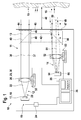
- FIG. 1 schematically a measuring device 10 according to the invention for optical distance measurement with the most important components to describe their function is shown.
- the measuring device 10 has a housing 11, in which a transmitting device 12 for emitting optical measuring radiation 13 and a receiving device 14 for detecting returning from a target object 15 measuring radiation 16 are arranged.
- the transmitting device 12 includes a light source, which is realized by a semiconductor laser diode 18 in the illustrated embodiment.
- the laser diode 18 emits a laser beam 20 in the form of a light beam 22 visible to the human eye.
- the laser diode 18 is operated via a control unit 24, which by a corresponding electronics generates a temporal modulation of an electrical input signal 19 of the laser diode 18.
- a modulation of the diode current it is possible to achieve that the optical measuring radiation 13, which is used for measuring the distance, is likewise modulated in its intensity in the desired manner over time.
- the laser beam 20 then passes through a collimating lens 26 in the form of a lens 28, which in Fig. 1 represented in a simplified manner in the form of a single lens.
- the objective 28 is optionally located on an adjustment mimic 32, which in principle makes it possible to change the position of the objective in all three spatial directions, for example for adjustment purposes.
- the collimating optics 26 may also already be part of the laser diode 18 or be permanently connected thereto.
- an amplitude-modulated signal, for example, of the measuring radiation 13 results in the form of a nearly parallel light bundle 37 which propagates along an optical axis 38 of the transmitting unit 12.
- the transmitting device 12 may also be a preferably switchable beam deflection 40 are located, which allows the measuring radiation 13 completely or partially bypassing the target object 15 directly, that is, device internally to redirect to the receiving device 14. In this way, a device-internal reference path 42 can be generated, which allows a calibration or a comparison of the measuring device.
- the measuring radiation 13 leaves the housing 11 of the measuring device through an optical window 44 in the end wall 45 of the measuring device 10.
- the opening of the optical window 44 can be secured, for example, by a shutter 46.
- the measuring device 10 is then aligned with a target object 15 whose distance 48 to the measuring device 10 is to be determined.
- the signal 16 reflected or scattered at the desired target object 15 forms returning optical Measuring radiation 16 in the form of a returning beam 49 and 50, which comes back to a certain extent back into the measuring device 10.
- the returning measuring radiation 16 is coupled into the measuring device 10 and then hits, as in Fig. 1 shown on a receiving optics 52nd
- Fig. 1 By way of example, two returning measuring beams 49 and 50 for two different target distances 48 are shown for clarification.
- the optical measuring radiation 16 returning from the target object 15 falls approximately parallel to the optical axis 51 of the receiving device 14. This case is in the embodiment of Fig. 1 represented by the measuring beam 49.
- the returning measuring radiation 16 incident in the measuring device is inclined more and more with respect to the optical axis 51 of the receiving device 14 due to a parallax.
- a returning measuring beam in the vicinity of the measuring device is in Fig. 1 the beam 50 drawn.
- the receiving optics 52 which are in Fig. 1 is also symbolized only schematically by a single lens, the beam focuses the returning measuring radiation 16 on the detection surface 66 of a receiving device 14 provided in the receiving detector 54.
- the detector 54 has for detecting the optical measuring radiation on a plurality of pixels. Each of the pixels has at least one photosensitive SPAD.
- the SPADs provided in the detection surface 66 which are arranged individually or in groups in pixels matrix-like and connected to an evaluation device 36, the incident returning measuring radiation 16 is converted into an electrical signal 55 and supplied to the further evaluation in the evaluation device 36 ,
- the electrical signal 55 can be regarded as a digital signal due to inherent properties of the SPADs, which represents a count rate of incident on the respective pixels of the detection surface 66 photons.
- the detection signals generated by a single SPAD or a combination of SPADs can be supplied to one or more distance determination devices (s) contained in an evaluation device 36.
- the distance determination device can add up the detection signals and generate therefrom a signal which corresponds to a time-dependent intensity of the light signal incident on the respective SPAD or the light intensity.
- This signal in relation to an excitation signal which indicates the time profile of the photon rate emitted by the transmitting device, it is possible to deduce a photon flight time from the transmitting device to the target object and back again to the receiving device.
- the transmitting device for example, periodically modulates the emitted light in a sinusoidal manner, a time of flight can be determined from a phase difference between the emitted and the detected measuring radiation.
- single photon avalanche diode sometimes referred to as a single photon avalanche diode, Geiger mode avalanche photodiode or G-APD
- SPAD single photon avalanche diode
- G-APD Geiger mode avalanche photodiode
- a fundamental difference between a SPAD and a conventional avalanche photodiode may be that the SPAD may be specifically designed to operate at a bias in the reverse direction that is above the breakdown voltage of the diode.
- This mode of operation is also called Geiger mode, in analogy to a Geiger counter.
- the electric field within the pn junction may be so strong that a single charge carrier injected into the depletion zone may initiate a self-sustaining avalanche current.
- the current may increase to a macroscopic level, for example in the range of mA, within a period of less than 1 ns.
- the current may be maintained until the avalanche is quenched by lowering the bias to a level below the breakdown voltage, thus breaking off the avalanche current.
- a simple damping circuit may consist of a simple resistor connected in series with the SPAD. The avalanche current is simply damped even due to the resulting voltage drop across the high-impedance series resistor.
- SPAD After the avalanche current has been damped, SPAD recovers and the SPAD is again able to fire again. However, while the avalanche current is flowing and during dampening and subsequent recovery of the bias, the SPAD may not be able to detect additional photons during a dead time ⁇ .
- the count rate determined by a single SPAD at a low rate of photons absorbed may be approximately proportional to the photon absorption rate.
- the count rate starts to saturate at a photon absorption rate slightly less than the inverse dead time 1 / ⁇ .
- the count rate even decreases until it completely collapses above a photon absorption rate, for example, in the range above 10 2 MHz, since at such high photon absorption rates, the SPAD is already triggered again before the voltage has fully recovered, and thus no interruption of the avalanche current can come.
- the efficiency of a paralyzable detector such as a SPAD thus decreases sharply at high photon currents as soon as the photon rate absorbed by the SPAD becomes large compared to an inverse dead time of the SPAD.
- the maximum detectable intensity (power per area) or the maximum detectable photon current or photon rate results in an upper limit for the maximum detectable intensity (power per area) or the maximum detectable photon current or photon rate.
- the photon rate absorbed per detector can be lowered by distributing the light output over several SPADs.
- the detection efficiency at high light outputs, as they can occur especially at short measurement distances, can be improved.
- the light output can be understood as meaning the entire light output detected by the receiving lens of the measuring radiation returning from the target object.
- Fig. 3 shows two SPADs 101, 101 ', whose detection signals are each forwarded to an OR gate 103.
- the OR gate 103 acts as a combiner 104 by receiving both detection signals from the first SPAD 101 and detection signals from the second SPAD 101 'and outputs at output 105 a combined signal of these input signals.
- the situation may be more complicated when using a combiner that combines the detection signals of several individual SPADs on a bus.
- the dead time attributable to the bus can result in additional efficiency losses compared to a fully parallel evaluation of a set of SPADs.
- a possible connection shows Fig. 4 ,
- the event rate 106 on the bus is represented in terms of a rate 107-1, 107-2, 107-3 of absorbed photons in three SPADs.
- the dead time ⁇ 1 of a SPAD is in each case 50 ns
- the dead time ⁇ 2 of the bus is 10 ns. It will be appreciated, for example, that the absorption event 108 of a photon by the second SPAD on the bus is not output as a separate count signal because it falls within the dead time ⁇ 2 of the bus.
- an effective dead time of an entire system consisting of a plurality of SPADs connected to a bus can be shortened.
- the effective dead time of the overall system results from a combination of the dead time of the individual SPADs and the duration of the signals shortened by the shorteners.
- the count rates on the bus are exemplified as a function of a rate of absorbed photons per pixel for a combination of one, four, nine, and sixteen SPADs, respectively.
- the SPAD dead time ⁇ 1 is 50 ns
- the bus dead time ⁇ 2 is 10 ns. Due to the deadtime of the bus, the maximum of the family of curves strives with increasing number of combined SPADs against a limit value (inverse bus dead time). It becomes clear that the dead time of the bus or of the combiner represents an optimization variable. In general, such a bus dead time may be significantly less than the dead time of a SPAD, so combining SPAD detection signals may result in count rates that are higher than the count rates of a single SPAD. Without a combiner or a bus, these higher count rates can only be realized by completely parallel evaluation with additional distance determination devices.
- Fig. 6 schematically shows a detection surface 110 of a detection device 54 for a laser distance measuring device with uncorrected parallax.
- circular laser spots 109 or laser spots the diameter of which varies as a function of a distance L between the measuring device and the target object, are indicated on the detection surface 110.
- the laser radiation was assumed to be at a divergence of 1 mrad.
- the parallax axis is here assumed to be the intersection line between a detection surface plane and a plane spanned by the optical axis of the receiving optics and the laser beam axis of the distance measuring device. It can be seen that in a first region 114 in which the laser spot 109 is incident, when the laser beam is reflected back from a distant target, small pixels are provided, each containing only a single SPAD.
- the laser spot 109 In a region 115 in which the laser spot 109 'impinges when the target is about 0.5 to 1 m away, larger pixels are provided with four SPADs each. In a further region 116, in which the laser spot 109 "impinges in the case of very close target objects, particularly large pixels with 8 or 16 SPADs are provided, the receiving optics being optimized so that the best possible imaging quality, ie the smallest possible laser spot diameter the detection surface is reached at the greatest distance of the target object.
- the laser spot 109 is relatively small due to the sharp image.
- the intensity of the incident light which is composed of returning measuring and background radiation, is relatively low due to the small proportion of the measuring radiation from the distant target object.
- a total of more measuring radiation is reflected or scattered by the target object back to the detection surface 110.
- the measuring radiation is no longer focused on the detection surface 110 by the fix-focus receiving optics.
- location-dependent configuration of the size of the pixels 101 contained in the detection surface 110 can be achieved on the one hand that both at large distances of the target object and at small distances of the target object, a laser spot 109 each meets a plurality of pixels 111 and can be evaluated by them ,
- the size of the active detection surface can be optimally adapted to the size of the laser spot and thus the signal-to-noise ratio can be optimized.
- the dynamic range of the SPADs can also be optimally utilized, since the light intensity of the incident light (laser and background portion) is smaller at long distances than at small distances.
- the area of the individual SPADs can therefore be reduced for the detector surfaces which are only exposed to received measuring radiation at short distances.
- the number of SPADs 101 contained in the individual pixels 111 can be increased while the SPAD area remains the same.
- Fig. 7 shows an embodiment of a detection surface 110 'for a coaxial laser rangefinder or laser rangefinder with corrected parallax.
- a correction can be achieved by means of a near-field element or alternative known methods.
- substantially the aberration dominates through the finite depth of field of the receiving optics, so that a concentric arrangement of the pixels of the same size is advantageous.
- a laser beam returning from a faraway target is well focused and produces a relatively small laser spot 109 near the center 122 of the detection surface 110 ', that is, near the optical axis piercing point of the receiving optics through the detection surface plane.
- a laser beam returning from a closer target produces a substantially larger diameter laser spot 109.
- the pixels 111 have a smaller area and a smaller number of SPADs 101 contained in the vicinity of the center 122 than remote from the center 122 of the detection area 110 '. that is, at the edge of the detection area.
- FIG. 8 to 10 For example, individual elements as used to implement a receiver according to embodiments of the present invention are shown as a block diagram.
- Fig. 8 1 shows a pixel 111 with a single SPAD 101.
- the pixel is connected to a distance determiner 130.
- Fig. 9 shows two pixels 111, 111 ', each with a SPAD 101, 101'.
- the pixels 111, 111 ' are connected to a multiplexer 140, which selectively passes the detection signals supplied by the pixels 111, 111' to a distance determining device 130.
- Fig. 10 an arrangement of two pixels 111, 111 'is shown, each with nine SPADs 101, 101'.
- the detection signals from the individual SPADs 101, 101 ' are forwarded to a combiner 160, 160', if appropriate after a time delay caused by additional delay elements 150, 150 '.
- the delay can be used to compensate for differences in transit time and thus the temporal synchronization of the SPADs of a pixel or different pixels.
- the detection signals are combined with each other.
- the signals generated by the SPADs can be shortened in time by means of pulse shorteners 155, 155 '.
- the combined detection signals are passed from the combiners 160, 160 'to a multiplexer 140 and from there to a distance determining device 130.
- N 92 pixels 111.
- 48 pixels have only a single SPAD
- 24 pixels each have four SPADs in a 2x2 array
- 20 pixels each have 9 SPADs in a 3x3 arrangement.
- Each pixel 111 with more than one SPAD 101 is exactly connected to a combiner 160, 160 '.
- the outputs of the pixels 111 with only one SPAD and the combiner 160 are connected to inputs of K multiplexers 140, respectively.
- FIG. 11 A hatched area indicates an effective detector area 170 comprising those pixels 111 that are actually illuminated by the laser light of the laser spot 109 and from which a distance measurement to the target object can be performed.
- the individual pixels can be operated independently of each other.
- a phase evaluation of a continuous wave or alternatively a time-of-flight evaluation of a pulse for each individual pixel can be carried out.
- a combination of several SPADs into pixels can be configured spatially in such a way that the signal-to-noise ratio at both large and small distances, in particular under strong background lighting with a few distance determination devices can be optimized. This can be achieved via a location-dependent adaptation of the size of the pixels or the number of SPADs that are combined to form a pixel.
- the type of arrangement of optional pixels with only one SPAD or pixels with different size and number of SPADs, optimized especially for increasing the signal-to-noise ratio in a laser rangefinder, represents one of the distinguishing features of both conventional laser rangefinders and 3D cameras.
- This arrangement can reduce the requirements for an adjustment of an optical system within the measuring device and can at the same time contribute to an optimized signal-to-noise ratio, even if the receiving device is not located in the image plane of the optical system, as occurs, for example, in fixed-focus systems can.
- a detection surface can be dimensioned so large that the requirements for the adjustment of the receiving optics can be reduced.
- the influence of optical aberrations, in particular the defocusing errors due to insufficient depth of field, can be minimized.
- the demands on the optical quality of the receiving optics can be reduced.
- Another advantage can be the optimization of the signal-to-noise ratio, especially for large measurement distances under high background light content. This can be achieved by optimally adapting, ie minimizing, the effective detection area at all distances to the size of the actually imaged laser measurement spot in the detection plane. Once the measurement has been completed, the signals of only those individual SPADs or pixels with several SPADs that actually receive laser radiation can be evaluated. As a result, the effective detection area can be reduced and the noise contribution of the background light can be minimized, which can be synonymous with an improvement in the signal-to-noise ratio.
- Another advantage may be that fewer ranging devices are needed than SPADs due to the merging of multiple SPADs within a pixel. This can reduce a required chip area of an integrated circuit. Especially with laser rangefinders, which typically operate with a fixed focal length, this advantage can play an important role, since the laser spot diameter can then vary depending on the distance of the target object. Fig. 6 illustrates this for a system in which the parallax error is not corrected. In order to optimize the signal-to-noise ratio as described above by minimizing the effective detection area, with larger laser spot diameters, that is usually at smaller distances of the target object, accordingly only a lower resolution of the detector may be required. This circumstance can be exploited by the location-dependent combination of SPADs to pixels.
- the effective detection area that is to say the area which is taken into account in the evaluation of the measurement
- the number of distance determination devices required can be reduced even further by additionally using multiplexing in addition to the combination of SPADs becomes.
- the pixels receiving laser radiation can first be identified and then distributed to the distance determination devices for the actual measurement. If N is the total number of pixels with one or more SPADs and M is the number of distance estimators available for evaluation, then N / M preliminary measurements must be performed for identification at maximum. The measuring task can therefore be carried out with a few measurements, ideally with a single measurement.
- Another advantage may be that individual pixels can be calibrated independently of each other, for example, in terms of phase offset.
Abstract
Es wird eine Messvorrichtung (10) zur optischen Messung einer Entfernung zu einem Zielobjekt (15) beschrieben. Die Messvorrichtung (10) weist eine Sendeeinrichtung (12) zur Aussendung optischer Messstrahlung (13) auf das Zielobjekt (15) hin, eine Empfangseinrichtung (14) mit einer Detektionsfläche (66) zur Detektion von von dem Zielobjekt (15) zurücklaufender optischer Messstrahlung (16) und eine Auswerteeinrichtung (36) auf. Die Detektionsfläche (66) weist eine Vielzahl von Pixeln auf, wobei jedes Pixel mindestens eine SPAD (single photon avalanche diode) aufweist, wobei wenigstens einige Pixel (111) jeweils eine Mehrzahl von SPADs (101) enthalten und wobei jedes der Vielzahl von Pixeln mit der Auswerteeinrichtung (36) verbunden ist. Die Sendeeinrichtung und die Empfangseinrichtung sind derart ausgelegt, dass von dem Zielobjekt zurücklaufende optische Messstrahlung eine Mehrzahl von Pixeln gleichzeitig beleuchtet. Die Auswerteeinrichtung ist derart ausgelegt, eine Entfernung zwischen der Messvorrichtung und dem Zielobjekt basierend auf einer Auswertung von Detektionssignalen mehrerer Pixel zu ermitteln.A measuring device (10) for the optical measurement of a distance to a target object (15) is described. The measuring device (10) has a transmitting device (12) for emitting optical measuring radiation (13) toward the target object (15), a receiving device (14) having a detection surface (66) for detecting optical measuring radiation returning from the target object (15). 16) and an evaluation device (36). The detection surface (66) comprises a plurality of pixels, each pixel having at least one SPAD (single photon avalanche diode), wherein at least some pixels (111) each include a plurality of SPADs (101) and wherein each of the plurality of pixels the evaluation device (36) is connected. The transmitting device and the receiving device are designed in such a way that optical measuring radiation returning from the target object simultaneously illuminates a plurality of pixels. The evaluation device is designed to determine a distance between the measuring device and the target object based on an evaluation of detection signals of a plurality of pixels.
Description
Die Erfindung betrifft eine Messvorrichtung zur Messung einer Entfernung zwischen der Messvorrichtung und einem Zielobjekt mit Hilfe von optischer Messstrahlung.The invention relates to a measuring device for measuring a distance between the measuring device and a target object with the aid of optical measuring radiation.
Es sind optische Entfernungsmessgeräte bekannt, die einen zeitlich modulierten Lichtstrahl in Richtung auf ein Zielobjekt hin, dessen Abstand zu dem Messgerät ermittelt werden soll, ausrichten. Das von dem angepeilten Zielobjekt reflektierte oder gestreute, rücklaufende Licht wird von dem Gerät zumindest teilweise detektiert und zur Ermittlung der zu messenden Entfernung verwendet. Ein typischer Messbereich liegt dabei in einem Bereich von Entfernungen von wenigen Zentimetern bis zu mehreren 100 Metern.Optical distance measuring devices are known which align a time-modulated light beam in the direction of a target object whose distance from the measuring device is to be determined. The returning light reflected or scattered by the targeted target object is at least partially detected by the device and used to determine the distance to be measured. A typical measuring range is in a range of distances of a few centimeters to several 100 meters.
Um die Entfernung zu dem Zielobjekt mit einem Lichtstrahl messen zu können, wird der Lichtstrahl beispielsweise in seiner Intensität zeitlich moduliert. Es können beispielsweise Lichtpulse ausgesendet werden und eine Laufzeit eines Lichtpulses von der Aussendung bis zur Detektion gemessen werden und daraus die Entfernung zu dem Zielobjekt errechnet werden. Hierzu müssen jedoch sehr kurze Lichtpulse ausgesendet werden und eine sehr schnelle Detektionselektronik verwendet werden, um ausreichend genaue Messergebnisse erhalten zu können. Alternativ kann ein Lichtstrahl in seiner Intensität zeitlich periodisch moduliert werden und eine Phasenverschiebung zwischen dem ausgesendeten und dem detektierten Lichtsignal verwendet werden, um die Laufzeit und damit die Entfernung zum Zielobjekt zu bestimmen. Das Prinzip der Laserentfernungsmessung ist allgemein unter der Bezeichnung "Time of Flight Ranging" beispielsweise mit kontinuierlicher Modulation der Intensität des Laserstrahls bekannt.In order to be able to measure the distance to the target object with a light beam, the light beam is, for example, time-modulated in its intensity. For example, light pulses can be emitted and a transit time of a light pulse can be measured from the emission to the detection and from this the distance to the target object can be calculated. For this, however, very short light pulses must be sent out and a very fast detection electronics are used in order to obtain sufficiently accurate measurement results. Alternatively, a light beam in its intensity can be periodically modulated in time and a phase shift be used between the emitted and the detected light signal to determine the transit time and thus the distance to the target object. The principle of laser distance measurement is generally known by the term "time of flight ranging", for example with continuous modulation of the intensity of the laser beam.
Es sind ferner sogenannte dreidimensionale (3D) Kameras bekannt, bei denen zusätzlich zu einer optischen Abbildung eines aufzunehmenden Objektes auch der jeweilige Abstand eines Bereichs auf der Oberfläche des aufzunehmenden Objektes zu der Kamera detektiert werden soll. Die Kamera weist hierzu eine abbildende Optik auf, die ein Bild des Objektes scharf auf eine Oberfläche eines dahinter angeordneten Detektors projiziert. Der Detektor weist dabei eine Vielzahl Matrix-artig angeordneter Pixel auf. Jedes der Pixel kann dabei eine Bildinformation wie beispielsweise eine Farbe oder Lichtintensität des von einem Oberflächenbereichs des Zielobjekts reflektierten Lichtes ermitteln. Zusätzlich kann eine Information über eine Entfernung zwischen der Kamera und dem entsprechenden Oberflächenbereich des Zielobjekts ermittelt werden. Hierzu kann das Zielobjekt mit zeitlich modulierter Laserstrahlung beleuchtet werden und die von dem Zielobjekt rückreflektierte und auf den Detektor mit Hilfe einer Abbildungsoptik abgebildete Strahlung durch Bestimmen der Flugzeit dazu verwendet werden, um eine ortsaufgelöste Information über Entfernungen zu den jeweiligen Oberflächenbereichen des Zielobjektes zu ermitteln.Furthermore, so-called three-dimensional (3D) cameras are known in which, in addition to an optical image of an object to be recorded, the respective distance of an area on the surface of the object to be photographed to the camera is to be detected. For this purpose, the camera has imaging optics which project an image of the object sharply onto a surface of a detector arranged behind it. The detector has a plurality of matrix-like arranged pixels. Each of the pixels can thereby determine image information such as, for example, a color or light intensity of the light reflected from a surface region of the target object. In addition, information about a distance between the camera and the corresponding surface area of the target object can be obtained. For this purpose, the target object can be illuminated with time-modulated laser radiation and the radiation reflected back from the target object and imaged on the detector by means of imaging optics can be used to determine spatially resolved information about distances to the respective surface regions of the target object.
Allerdings benötigt eine solche dreidimensionale Kamera zusätzlich zu einem ortsauflösenden Detektor mit einer Vielzahl von Pixeln auch eine abbildende Optik, um jeden Oberflächenbereich des Zielobjektes genau auf ein Pixel abzubilden, wobei das von diesem Pixel ermittelte Detektionssignal dann zur Bestimmung der Entfernung zu dem jeweiligen Oberflächenbereich herangezogen werden kann. Dies erfordert eine verhältnismäßig komplizierte, fokussierende Optik sowie die Möglichkeit einer einzelnen Auswertung von Detektionssignalen jedes der Pixel.However, such a three-dimensional camera, in addition to a spatial resolution detector having a plurality of pixels, also requires imaging optics to accurately map each surface area of the target to one pixel, and the detection signal determined by that pixel is then used to determine the distance to the respective surface area can. This requires a relatively complicated, focusing optics as well as the possibility of a single evaluation of detection signals of each of the pixels.
Im Gegensatz hierzu werden einfache Entfernungsmessgeräte lediglich dazu verwendet, eine Entfernung zwischen dem Messgerät und dem Zielobjekt bzw. einem mit einem Laserstrahl anvisierten Punkt auf dem Zielobjekt zu ermitteln. Die Entfernung braucht dabei nicht ortsaufgelöst bestimmt werden. Es genügt in der Regel, eine gemittelte Entfernung zu bestimmen. Solche Entfernungsmessgeräte werden häufig in Hand-gehaltenen Geräten eingesetzt, um beispielsweise innerhalb eines Raumes den Abstand eines bestimmten Ortes zu umgebenden Zielobjekten wie zum Beispiel Wänden oder Einrichtungsgegenständen zu bestimmen. Ein Hand-gehaltenes Entfernungsmessgerät sollte dabei vorzugsweise einen möglichst einfachen, robusten und kostengünstigen Aufbau aufweisen und eine einfache Bedienung ermöglichen.In contrast, simple rangefinders are merely used to determine a distance between the meter and the target object or a laser beam targeted point on the target object. The distance need not be determined spatially resolved. It is usually sufficient to determine an average distance. Such rangefinders are often used in handheld devices to determine, for example within a room, the distance of a particular location to surrounding targets such as walls or furnishings. A hand-held distance measuring device should preferably have the simplest possible, robust and cost-effective design and allow easy operation.
Aus der
Da das beschriebene herkömmliche Entfernungsmessgerät lichtempfindliche Elemente wie z.B. PIN-Dioden oder APDs (Avalanche Photo Diode) verwendet, die ein analoges Messsignal mit hoher Bandbreite bereitstellen, kann es notwendig sein, zur Auswertung dieser analogen Messsignale eine komplizierte Auswerteelektronik zu verwenden., Die analog arbeitenden lichtempfindlichen Elemente sind häufig mit einer ansonsten in dem Messgerät verwendeten CMOS-Technologie nicht kompatibel.Since the conventional distance measuring apparatus described has photosensitive elements such as e.g. Using PIN diodes or APDs (Avalanche Photo Diode), which provide a high-bandwidth analog measurement signal, it may be necessary to use a sophisticated evaluation electronics to evaluate these analog measurement signals. The analog-type photosensitive elements are often associated with an otherwise in the Meter used CMOS technology incompatible.
Es kann ein Bedarf an einer Messvorrichtung zur optischen Entfernungsmessung bestehen, die, insbesondere im Vergleich zu den zuvor beschriebenen herkömmlichen Entfernungsmessgeräten, einen vereinfachten Aufbau von darin verwendeten Elektronikkomponenten, insbesondere von Auswertekomponenten zur Auswertung von Detektionssignalen, zulässt. Ferner kann ein Bedarf an einer Entfernungsmessvorrichtung bestehen, die weitgehend mit einer einzigen Fertigungstechnologie, beispielsweise einer CMOS-Technologie, gefertigt werden kann.There may be a need for an optical distance measurement measuring apparatus which, particularly in comparison to the conventional distance measuring apparatuses described above, has a simplified structure of electronic components used therein, in particular of evaluation components for the evaluation of detection signals, permits. Further, there may be a need for a rangefinder that can be fabricated largely with a single manufacturing technology, such as CMOS technology.
Ferner kann ein Bedarf an einer Entfernungsmessvorrichtung bestehen, die möglichst zumindest einen der nachfolgenden Vorteile aufweist:
- Aufweitung einer Justagetoleranz einer Empfangsoptik der Entfernungsmessvorrichtung bezogen auf einen Detektor;
- Reduzierung einer Komplexität und von Anforderungen an eine Empfangsoptik;
- Erhöhung eines Dynamikbereiches insbesondere bei der Messung kleiner Entfernungen;
- Optimierung eines Signal-Rausch-Verhältnisses insbesondere bei der Messung großer Entfernungen; und/oder
- Verringerung einer für die Auswertung benötigten Chipfläche einer integrierten Schaltung.
- Expansion of an adjustment tolerance of a receiving optical system of the distance measuring device relative to a detector;
- Reducing complexity and requirements for receiving optics;
- Increasing a dynamic range, especially when measuring small distances;
- Optimization of a signal-to-noise ratio, especially when measuring long distances; and or
- Reduction of a chip area of an integrated circuit required for the evaluation.
Die erfindungsgemäße Messvorrichtung zur optischen Entfernungsmessung weist eine Sendeeinrichtung zur Aussendung optischer Messstrahlung auf ein Zielobjekt hin, eine Empfangseinrichtung mit einer Detektionsfläche zur Detektion von von dem Zielobjekt zurücklaufender optischer Messstrahlung und eine Auswerteeinrichtung auf. Die Detektionsfläche der Empfangseinrichtung weist dabei eine Vielzahl von Pixeln auf, wobei jedes Pixel mindestens eine SPAD (Single Photon Avalanche Diode; Einzelphotonenlawinendiode) aufweist. Jedes der Vielzahl von Pixeln ist mit der Auswerteeinrichtung direkt oder indirekt über weitere zwischengeschaltete Bauelemente verbunden. Die Sendeeinrichtung und die Empfangseinrichtung sind dabei derart ausgelegt, dass von dem Zielobjekt zurücklaufende optische Messstrahlung bei einer vorsehungsgemäßen Verwendung der Entfernungsmesseinrichtung jeweils eine Mehrzahl von Pixeln gleichzeitig beleuchtet. Die Auswerteeinrichtung ist dabei dazu ausgelegt, eine Entfernung zwischen der Messvorrichtung und dem Zielobjekt basierend auf einer Auswertung von Detektionssignalen mehrerer Pixel, insbesondere mehrerer der gleichzeitig beleuchteten Pixel, zu ermitteln.The measuring device according to the invention for optical distance measurement has a transmitting device for emitting optical measuring radiation toward a target object, a receiving device having a detection surface for detecting optical measuring radiation returning from the target object and an evaluation device. The detection surface of the receiving device in this case has a multiplicity of pixels, each pixel having at least one SPAD (single photon avalanche diode). Each of the plurality of pixels is connected to the evaluation device directly or indirectly via further intermediate components. In this case, the transmitting device and the receiving device are designed in such a way that optical measuring radiation returning from the target object illuminates a plurality of pixels at the same time when the distance measuring device is used as intended. The evaluation device is designed to provide a distance between the measuring device and the target object based on an evaluation of Detecting signals of multiple pixels, in particular several of the simultaneously illuminated pixels to determine.
Die Sendeeinrichtung kann eine Lichtquelle, beispielsweise in Form einer LED, eines Lasers oder einer Laserdiode sein, die Licht zeitlich moduliert hin zu dem Zielobjekt aussendet. Die zeitliche Modulation kann hierbei kontinuierlich und/oder periodisch, beispielsweise sinusartig, erfolgen. Es können auch Pulszüge, beispielsweise nichtperiodisch wie z.B. in Form von sogenannten Pseudo-Noise-Pulsabfolgen ausgesendet werden.The transmitting device may be a light source, for example in the form of an LED, a laser or a laser diode, which emits light modulated in time to the target object. The temporal modulation can take place continuously and / or periodically, for example sinusoidally. Pulse trains, for example non-periodic such as e.g. be emitted in the form of so-called pseudo-noise pulse sequences.
Die Empfangseinrichtung kann sich von Empfangseinrichtungen, wie sie in herkömmlichen Entfernungsmessgeräten verwendet werden, dahingehend unterscheiden, dass anstatt analog arbeitender lichtempfindlicher Elemente, die gegebenenfalls zusammengeschaltet werden können, um ein analoges Gesamtsignal bereitzustellen, eine Vielzahl von Pixeln innerhalb einer Detektionsfläche vorgesehen sein kann, wobei jedes Pixel eine oder mehrere SPADs beinhaltet. Wie weiter unten noch detaillierter erläutert, ist eine SPAD dabei ein lichtempfindliches Element, das abhängig von einer auftreffenden Lichtintensität ein digitales Detektionssignal liefert. Jedes der Pixel kann dabei direkt oder beispielsweise unter Zwischenschaltung eines Multiplexers, der dazu ausgelegt ist, Detektionssignale mehrerer Pixel selektiv weiterzuleiten, mit der Auswerteeinrichtung verbunden sein. Auf diese Weise kann zum Beispiel erreicht werden, dass Detektionssignale einzelner Pixel oder einer Gruppe von Pixeln unabhängig von Detektionssignalen anderer Pixel von der Auswerteeinrichtung ausgewertet werden können.The receiving device may be different from receiving devices as used in conventional rangefinders in that, instead of analogously operating photosensitive elements, which may optionally be interconnected to provide a total analog signal, a plurality of pixels may be provided within a detection area, each Pixel contains one or more SPADs. As will be explained in more detail below, a SPAD is a photosensitive element that delivers a digital detection signal as a function of an incident light intensity. Each of the pixels can be connected to the evaluation device directly or, for example, with the interposition of a multiplexer which is designed to selectively transmit detection signals of several pixels. In this way it can be achieved, for example, that detection signals of individual pixels or of a group of pixels can be evaluated by the evaluation device independently of detection signals of other pixels.
Die Sendeeinrichtung und die Empfangseinrichtung sind derart ausgelegt und aufeinander abgestimmt, dass von dem Zielobjekt zurücklaufende optische Messstrahlung unter normalen Messbedingungen, das heißt beispielsweise bei Messabständen von wenigen Zentimetern bis zu einigen 100 Metern, eine Mehrzahl von Pixeln gleichzeitig beleuchtet werden. Die Tatsache, dass eine Mehrzahl von Pixeln gleichzeitig beleuchtet wird, soll hierbei jedoch nicht wie bei herkömmlichen 3D-Kameras dazu benutzt werden, ein Abbild des Zielobjektes bzw. eine räumliche Auflösung hinsichtlich der Entfernung zu einzelnen Teilbereichen auf einer Oberfläche des Zielobjektes zu detektieren, sondern soll, wie weiter unten noch detaillierter erläutert, unter anderem Vorteile hinsichtlich einer Detektionsempfindlichkeit und/oder einer Justagetoleranz ermöglichen. Die Entfernung zwischen der Messvorrichtung und dem Zielobjekt wird dabei basierend auf einer Auswertung von Detektionssignalen mehrerer Pixel, insbesondere mehrerer der gleichzeitig beleuchteten Pixel, ermittelt.The transmitting device and the receiving device are designed and matched to one another such that optical measuring radiation returning from the target object is illuminated simultaneously under normal measuring conditions, that is, for example at measuring distances of a few centimeters to a few hundred meters. However, the fact that a plurality of pixels are illuminated simultaneously is not intended to be used as in conventional 3D cameras be to capture an image of the target object or a spatial resolution with respect to the distance to individual sub-areas on a surface of the target object, but should, as explained below in more detail, inter alia, allow advantages in terms of a detection sensitivity and / or an adjustment tolerance. The distance between the measuring device and the target object is determined based on an evaluation of detection signals of a plurality of pixels, in particular a plurality of simultaneously illuminated pixels.
Die Sendeeinrichtung kann hierzu einen Messstrahl aussenden, dessen Querschnitt ausreichend groß ist, dass der von dem Zielobjekt zurücklaufende Anteil des Messstrahls stets eine Mehrzahl von Pixeln beleuchtet. Um die von dem Zielobjekt zurücklaufende Messstrahlung zu bündeln und auf die Detektionsfläche zu leiten, um auf diese Weise für ein ausreichend starkes Detektionssignal zu sorgen, kann innerhalb eines optischen Weges von der Sendeeinrichtung zu der Empfangseinrichtung eine einfache Optik, beispielsweise in Form einer oder mehrerer Linsen, vorgesehen sein. Diese einfache Optik kann kostensparend und aufwandsreduzierend als nicht-automatisch-fokussierende Optik ("Fix-Fokus") ausgestaltet sein. Da eine solche nicht-automatisch-fokussierende Optik mit fester Brennweite einen von dem Zielobjekt zurücklaufenden Messstrahl nur dann optimal, d.h. mit kleinstem Spot-Durchmesser, auf die Detektionsfläche der Empfangseinrichtung fokussieren kann, wenn sich das Zielobjekt in dem der Brennweite und Bildebene entsprechenden Objektabstand zu der Messvorrichtung befindet, kann die Anzahl von Pixeln, die durch von dem Zielobjekt zurücklaufende Messstrahlung gleichzeitig beleuchtet werden, in Abhängigkeit von einem Abstand zwischen dem Zielobjekt und dem Messobjekt variieren. Beispielsweise kann die Optimierung des optischen Empfangssystems für den Empfang von Messstrahlung von weit entfernten Zielobjekten mit großem Objektabstand bedeuten, dass Brennweite und Bildabstand so zu wählen sind, dass für den großen Objektabstand die geometrische Abbildungsbedingung erreicht wird. Somit kann bei großer Entfernung der kleinste Spot-Durchmesser in der Bildebene erreicht werden ("die Abbildung ist scharf"). Durch die Festlegung der Brennweite und Bildebene kann die Anzahl von Pixeln, die im Falle eines näher liegenden Zielobjektes beleuchtet werden, wesentlich größer sein als bei einem weit entfernten Zielobjekt. Bei einem näher liegenden Zielobjekt kann die zurücklaufende Messstrahlung nicht mehr scharf abgebildet werden, so dass der beleuchtete Bereich der Detektionsfläche entsprechend größer werden kann.For this purpose, the transmitting device can emit a measuring beam whose cross-section is sufficiently large that the portion of the measuring beam returning from the target object always illuminates a plurality of pixels. In order to focus the measuring radiation returning from the target object and to guide it to the detection surface in order to provide a sufficiently strong detection signal, a simple optical system, for example in the form of one or more lenses, can be provided within the optical path from the transmitting device to the receiving device , be provided. This simple optics can be designed to save costs and reduce costs as a non-automatic focusing optics ("fixed focus"). Since such a non-autofocusing optical system with a fixed focal length optimally, ie with the smallest spot diameter, can focus a measuring beam returning from the target object onto the detection surface of the receiving device when the target object approaches the object distance corresponding to the focal length and image plane of the measuring device, the number of pixels illuminated simultaneously by measuring radiation returning from the target object may vary depending on a distance between the target object and the measuring object. For example, the optimization of the optical receiving system for the reception of measuring radiation from distant targets with a large object distance can mean that focal length and image distance are to be selected such that the geometric imaging condition is achieved for the large object distance. Thus, at a great distance, the smallest spot diameter in the image plane can be achieved ("the image is sharp"). By defining the focal length and image plane, the number of pixels that are illuminated in the case of a closer target object can be significantly larger than with a distant target object. With a closer target object, the returning measuring radiation can no longer be sharply imaged, so that the illuminated area of the detection area can be correspondingly larger.
Da die Detektionssignale einzelner Pixel unabhängig voneinander ausgewertet können, können die Empfangseinrichtung und die Auswerteeinrichtung dazu ausgelegt werden, eine Entfernung zwischen der Messvorrichtung und dem Zielobjekt basierend auf einer Auswertung von Detektionssignalen ausschließlich von Pixeln, auf die Licht der von der Sendeeinrichtung beleuchteten Fläche des Zielobjektes rückgestrahlt wird, zu ermitteln. Mit anderen Worten kann die Auswerteeinrichtung beispielsweise zunächst in einer Vorabmessung ermitteln, welche der Pixel der Detektionsfläche tatsächlich Messstrahlung der Sendeeinrichtung empfangen und welche Pixel lediglich Hintergrundstrahlung detektieren, und kann anschließend für die tatsächliche Entfernungsbestimmung lediglich die Detektionssignale der von der Messstrahlung beleuchteten Pixel verwenden. Hierdurch kann ein Signal-Rausch-Verhältnis erheblich erhöht werden.Since the detection signals of individual pixels can be evaluated independently of one another, the receiving device and the evaluation device can be designed to radiate a distance between the measuring device and the target object based on an evaluation of detection signals excluding pixels, onto which the light of the surface illuminated by the transmitting device of the target object is to determine. In other words, the evaluation device can first determine, for example, in a preliminary measurement, which of the pixels of the detection surface actually receive measuring radiation of the transmitting device and which pixels only detect background radiation, and can subsequently use only the detection signals of the pixels illuminated by the measuring radiation for the actual distance determination. As a result, a signal-to-noise ratio can be increased considerably.
Um die Entfernung zwischen der Messvorrichtung und dem Zielobjekt ermitteln zu können, kann die Auswerteeinrichtung wenigstens eine Entfernungsbestimmungseinrichtung (teilweise auch als "Binning-Schema" bekannt) aufweisen. Die Entfernungsbestimmungseinrichtung kann dazu ausgelegt sein, eine Flugdauer von Messstrahlung zwischen einer Aussendung von der Sendeeinrichtung bis zu einer Detektion der von dem Zielobjekt zurücklaufenden Messstrahlung auf der Detektionsfläche zu ermitteln und daraus eine Entfernung zu bestimmen. Die Entfernungsbestimmungseinrichtung kann hierzu eine von der Sendeeinrichtung bereitgestellte Information über die zeitliche Modulation ausgesendeter Messstrahlung mit von der Empfangseinrichtung bereitgestellten Detektionssignalen vergleichen. Im Fall einer periodisch modulierten ausgesendeten Messstrahlung kann beispielsweise aus einem Phasenunterschied zwischen einem Aussendungssignal und einem Detektionssignal eine entsprechende Entfernung ermittelt werden.In order to be able to determine the distance between the measuring device and the target object, the evaluation device can have at least one distance determining device (sometimes also known as a "binning scheme"). The distance determination device can be designed to determine a flight duration of measurement radiation between a transmission from the transmission device to a detection of the measurement radiation returning from the target object on the detection surface and to determine therefrom a distance. For this purpose, the distance determination device can compare information provided by the transmitting device about the temporal modulation of emitted measuring radiation with detection signals provided by the receiving device. In the case of a periodically modulated emitted measuring radiation, for example, a corresponding distance can be determined from a phase difference between a transmission signal and a detection signal.
Prinzipiell kann eine einzige Entfernungsbestimmungseinrichtung für die Ermittlung einer Entfernung zwischen der Messvorrichtung und dem Zielobjekt genügen. Um die Anzahl von Entfernungsbestimmungseinrichtungen gering zu halten, kann es vorteilhaft sein, die Detektionssignale einzelner Pixel oder einer Gruppe von Pixeln zum Beispiel mit Hilfe eines Multiplexers nacheinander an eine Entfernungsbestimmungseinrichtung zu leiten. Aufgrund einer derart sequentiellen Verarbeitung von Detektionssignalen kann es zu einer Verlängerung einer Gesamtmessdauer kommen. Alternativ kann jedem der Pixel eine eigene Entfernungsbestimmungseinrichtung zugeordnet sein. In diesem Fall kann aus jedem der Detektionssignale der Vielzahl von Pixeln jeweils eine Entfernung bestimmt werden, möglicherweise zeitlich parallel zueinander, und aus der Vielzahl von bestimmten Entfernungen kann schließlich beispielsweise durch Mittelung eine letztendlich zu bestimmende Entfernung zwischen der Vorrichtung und dem Zielobjekt ermittelt werden. Allerdings kann es hierzu notwendig sein, eine sehr große Anzahl von Entfernungsbestimmungseinrichtungen in der Messvorrichtung vorzusehen, was den Aufbau und die Fertigung der Messvorrichtung kompliziert gestalten kann.In principle, a single distance determination device can suffice for determining a distance between the measuring device and the target object. In order to keep the number of distance-determining devices small, it may be advantageous for the detection signals of individual pixels or a group of pixels, for example by means of a multiplexer, successively to a distance-determining device to lead. Due to such a sequential processing of detection signals, it can lead to an extension of a total measurement duration. Alternatively, each of the pixels can be assigned its own distance determination device. In this case, a distance can be determined from each of the detection signals of the plurality of pixels, possibly temporally parallel to one another, and from the plurality of determined distances finally, for example, by averaging a finally determined distance between the device and the target object can be determined. However, for this purpose, it may be necessary to provide a very large number of distance determining devices in the measuring device, which can make the construction and manufacture of the measuring device complicated.
Sozusagen als Mittelweg zwischen diesen beiden extremen Alternativen kann eine Mehrzahl von Pixeln mit einer Entfernungsbestimmungseinrichtung verbunden sein und die Entfernungsbestimmungseinrichtung kann dazu ausgelegt sein, die Entfernung basierend auf Detektionssignalen der Mehrzahl von Pixeln zu bestimmen. Die Auswerteeinrichtung kann eine Mehrzahl von Entfernungsbestimmungseinrichtungen aufweisen und dazu ausgelegt sein, die Entfernung zwischen der Messvorrichtung und dem Zielobjekt basierend auf den von den Entfernungsbestimmungseinrichtungen bestimmten Entfernungen zu bestimmen, beispielsweise durch Mittelwertbildung.As a middle ground between these two extreme alternatives, a plurality of pixels may be connected to a distance-determining device, and the distance-determining device may be configured to determine the distance based on detection signals of the plurality of pixels. The evaluation device can have a plurality of distance determination devices and can be designed to determine the distance between the measurement device and the target object based on the distances determined by the distance determination devices, for example by averaging.
Eine SPAD kann die Eigenschaft aufweisen, dass sie nicht wie herkömmliche analog arbeitende lichtempfindliche Elemente ein von der auftreffenden Strahlung linear abhängiges Detektionssignal liefert, sondern mit jedem auftreffenden Photon ein einzelnes Signal erzeugt wird. Die SPAD ist nach dem Auftreffen eines Photons für eine gewisse Totzeit, die im Bereich von beispielsweise 1 bis 100 ns liegen kann, nicht erneut aktivierbar. Man spricht auch von einem paralysierbaren Ansprechverhalten. Die Zählrate, mit der eine SPAD auftreffende Photonen zählen kann, ist somit nach oben hin durch die Totzeit begrenzt. Es kann daher vorteilhaft sein, anstatt einer einzigen großflächigen SPAD mehrere kleinere SPADs innerhalb eines Pixels vorzusehen und beispielsweise Detektionssignale von in einem einzelnen Pixel enthaltenen SPADs mit Hilfe eines Kombinierers zu kombinieren. Der Kombinierer kann hierbei beispielsweise in Form eines ODER-Gatters oder in Form eines Busses ausgestaltet sein. Auf diese Weise kann die von dem Pixel maximal erreichbare Photonenzählrate erhöht werden bzw., anders ausgedrückt, die Totzeit des Pixels zwischen einzelnen Detektionsereignissen verkürzt werden. Ferner kann zwischen einer SPAD und einem Kombinierer oder Bus ein Pulsverkürzer angeordnet sein, um ein von der SPAD generiertes digitales Signal zeitlich zu verkürzen und dadurch eine verkürzte Gesamttotzeit und eine erhöhte Photonenzählrate des Systems zu ermöglichen.A SPAD may have the property of not providing a detection signal which is linearly dependent on the incident radiation, as conventional analog light-sensitive elements do, but producing a single signal with each incident photon. The SPAD is not reactivated after the impact of a photon for a certain dead time, which may range from, for example, 1 to 100 ns. One also speaks of a paralyzable response. The count rate with which a SPAD can count impinging photons is thus limited upwards by the dead time. It may therefore be advantageous, instead of a single large-area SPAD, to provide several smaller SPADs within one pixel and, for example, to combine detection signals of SPADs contained in a single pixel by means of a combiner. In this case, the combiner can be designed, for example, in the form of an OR gate or in the form of a bus. In this way, the maximum achievable by the pixel photon count rate can be increased In other words, the dead time of the pixel between individual detection events can be shortened. Further, a pulse shortener may be disposed between a SPAD and a combiner or bus to temporally shorten a digital signal generated by the SPAD, thereby enabling a shortened overall dead time and an increased photon counting rate of the system.
Die Anzahl von SPADs oder die Fläche von SPADs, die in einem Pixel enthalten sind, kann abhängig vom Ort des Pixels innerhalb der Detektionsfläche der Empfangseinrichtung variabel ausgewählt sein. Beispielsweise kann bekannt sein, dass die von dem Zielobjekt zurücklaufende Messstrahlung abhängig vom Abstand des Zielobjekts von der Messvorrichtung an einer anderen Position und/oder mit einer anderen Querschnittsfläche auf die Detektionsfläche der Empfangseinrichtung auftreffen kann. Die Anzahl bzw. die Fläche von SPADs innerhalb eines Pixels kann demnach ortsabhängig an die zu erwartende auftreffende Lichtintensität angepasst werden. Durch Anpassung der Flächen der SPADs und/oder Anzahl von SPADs innerhalb eines Pixels kann ein Dynamikbereich der Messvorrichtung optimiert werden. Durch Anpassung der Pixel-Flächen an eine Laserfleckgröße kann ein Signal-Rausch-Verhältnis optimiert werden.The number of SPADs or the area of SPADs contained in a pixel may be variably selected depending on the location of the pixel within the detection area of the receiving device. For example, it may be known that the measuring radiation returning from the target object can impinge on the detection surface of the receiving device depending on the distance of the target object from the measuring device at a different position and / or with a different cross-sectional area. The number or area of SPADs within a pixel can therefore be adapted to the expected incident light intensity depending on the location. By adapting the areas of the SPADs and / or the number of SPADs within a pixel, a dynamic range of the measuring device can be optimized. By adapting the pixel areas to a laser spot size, a signal-to-noise ratio can be optimized.
Wenn beispielsweise im Lichtweg zwischen der Sendeeinrichtung und der Empfangseinrichtung eine nicht-automatisch-fokussierende Optik, die für weitentfernte Zielobjekte abbildend bzw. optimal fokussierend ausgelegt ist, angeordnet ist, kann für weit entfernte Zielobjekte die zurücklaufende Messstrahlung mit einem kleinen Fleck- bzw. Spot-Durchmesser fokussiert werden. Innerhalb eines solchen Bereiches der Detektionsfläche kann es vorteilhaft sein, dass jedes der Pixel lediglich eine einzige SPAD oder nur wenige SPADs enthält. Wenn mit einer solchen Fix-Fokus-Messvorrichtung näher liegende Zielobjekte anvisiert werden, kann die zurücklaufende Messstrahlung auf der Detektionsfläche nicht als kleiner Fleck fokussiert werden, sondern trifft eventuell defokussiert auf eine größere Teilfläche der Detektionsfläche. Insgesamt werden in diesem Fall dann mehr Pixel beleuchtet als im Fall eines weit entfernt liegende Zielobjektes. Daher kann es vorteilhaft sein, in Randbereichen des beleuchteten Teilbereiches der Detektionsfläche jeweils eine Mehrzahl von SPADs zu einem einzelnen Pixel (oder "sub-array" oder "cluster" von SPADs) zusammenzufassen.If, for example, non-autofocusing optics which are designed for far-distant target objects or optimally focusing are arranged in the light path between the transmitting device and the receiving device, the returning measuring radiation with a small spotlight can be used for distant target objects. Diameter to be focused. Within such a region of the detection surface, it may be advantageous for each of the pixels to contain only a single SPAD or only a few SPADs. If target objects approaching closer to such a fix-focus measuring device are targeted, the returning measuring radiation on the detection surface can not be focused as a small spot, but possibly defocused, strikes a larger partial area of the detection surface. Overall, in this case, more pixels are illuminated than in the case of a distant target object. It may therefore be advantageous to combine in each case a plurality of SPADs into a single pixel (or "sub-array" or "cluster" of SPADs) in edge regions of the illuminated subarea of the detection surface.
Beispielsweise kann die Sendeeinrichtung und die Empfangseinrichtung nebeneinander entlang einer Parallaxenachse angeordnet sein. Solche sogenannte biaxiale Messsysteme können den Vorteil haben, dass keine aufwändige Strahlungsteilung zur Selektion des rücklaufenden Messstrahls notwendig ist. Der von der Sendeeinrichtung ausgestrahlte und von dem Zielobjekt zurücklaufende Messstrahl kann in diesem Fall je nach Entfernung des Zielobjektes an einer anderen Stelle entlang der Parallaxenachse auf die Detektionsfläche treffen und unterschiedliche Querschnitte aufweisen. In diesem Fall kann es vorteilhaft sein, die Anzahl von SPADs, die in einem Pixel enthalten sind, abhängig vom Ort des Pixels entlang der Parallaxenachse zu variieren. Insbesondere kann es vorteilhaft sein, die Anzahl von SPADs, die in einem Pixel enthalten sind, in Pixeln nahe der Sendeeinrichtung kleiner zu wählen als in Pixeln entfernt von der Sendeeinrichtung.For example, the transmitting device and the receiving device can be arranged side by side along a parallax axis. Such so-called biaxial measuring systems can have the advantage that no elaborate radiation division is necessary for the selection of the returning measuring beam. In this case, the measuring beam emitted by the transmitting device and returning from the target object, depending on the distance of the target object, can hit the detection surface at a different location along the parallax axis and have different cross sections. In this case, it may be advantageous to vary the number of SPADs contained in a pixel depending on the location of the pixel along the parallax axis. In particular, it may be advantageous to make the number of SPADs included in a pixel smaller in pixels near the transmitting device than in pixels remote from the transmitting device.
Alternativ können die Sendeeinrichtung und die Empfangseinrichtung koaxial zueinander angeordnet sein. Bei einer solchen monoaxialen Messvorrichtung kann beispielsweise mit Hilfe semitransparenter Spiegel erreicht werden, dass das Zentrum des von der rücklaufenden Strahlung beleuchteten Bereichs der Detektionsfläche unabhängig von der Entfernung des Zielobjekts weitgehend orts-konstant bleibt. Allerdings kann der Querschnitt des beleuchteten Bereichs auf der Detektionsfläche weiterhin von der Entfernung des Zielobjektes abhängen. Bei weit entfernten Zielobjekten und einer Optik mit weiter Brennweite kann es zu einem kleinen beleuchteten Fleck kommen, bei näher liegenden Zielobjekten zu einem größeren beleuchteten Fleck. Es kann vorteilhaft sein, die Anzahl von SPADs, die in einem Pixel enthalten sind, in Pixeln nahe dem Zentrum der Detektionsfläche kleiner zu wählen als in Pixeln entfernt von dem Zentrum der Detektionsfläche.Alternatively, the transmitting device and the receiving device can be arranged coaxially with one another. In such a monoaxial measuring device, it can be achieved, for example with the aid of semitransparent mirrors, that the center of the area of the detection surface illuminated by the returning radiation remains largely position-independent, independently of the distance of the target object. However, the cross-section of the illuminated area on the detection surface may still depend on the distance of the target object. With distant targets and a wide-focussed lens, a small illuminated spot may result, with closer targets to a larger illuminated spot. It may be advantageous to make the number of SPADs contained in a pixel smaller in pixels near the center of the detection area than in pixels away from the center of the detection area.
Mögliche Aspekte, Vorteile und Ausgestaltungen der Erfindung wurden vorangehend mit Bezug auf einzelne Ausführungsformen der Erfindung beschrieben. Die Beschreibung, die zugehörigen Figuren sowie die Ansprüche enthalten zahlreiche Merkmale in Kombination. Ein Fachmann wird diese Merkmale, insbesondere auch die Merkmale verschiedener Ausführungsbeispiele, auch einzeln betrachten und zu sinnvollen weiteren Kombinationen zusammenfassen.Possible aspects, advantages and embodiments of the invention have been described above with reference to individual embodiments of the invention. The description, the associated figures and the claims contain numerous features in combination. A person skilled in the art will consider these features, in particular also the features of different exemplary embodiments, individually and combine them into meaningful further combinations.
Nachfolgend werden Ausführungsformen der Erfindung und darin enthaltene Teilaspekte mit Bezug auf die beigefügten Figuren beschrieben. Die Figuren sind lediglich schematisch und nicht maßstabsgetreu. Gleiche oder ähnliche Bezugszeichen in den Figuren bezeichnen gleiche oder ähnliche Elemente.
-
Fig. 1 zeigt eine Messvorrichtung zur optischen Entfernungsmessung gemäß einer Ausführungsform der vorliegenden Erfindung. -
Fig. 2 zeigt beispielhaft eine Abhängigkeit einer Zählrate einer SPAD abhängig von einer Rate absorbierter Photonen pro Pixel. -
Fig. 3 zeigt eine schematisierte Schaltung von zwei SPADs, die mit einem Kombinierer verbunden sind, für eine Messvorrichtung gemäß einer Ausführungsform der vorliegenden Erfindung. -
Fig. 4 veranschaulicht ein Ansprechverhalten von drei SPADs und einem damit verbundenen Bus unter Berücksichtigung von Totzeiten für eine Messvorrichtung gemäß einer Ausführungsform der vorliegenden Erfindung. -
Fig. 5 zeigt beispielhaft eine Gesamtzählrate an einem mit mehreren SPADs verbundenen Bus in Abhängigkeit einer Rate absorbierter Photonen pro Pixel. -
Fig. 6 zeigt eine Draufsicht auf eine Detektionsfläche einer Empfangseinrichtung für eine Messvorrichtung gemäß einer Ausführungsform der vorliegenden Erfindung. -
Fig. 7 zeigt eine Draufsicht auf eine alternative Detektionsfläche einer Empfangseinrichtung für eine Messvorrichtung gemäß einer Ausführungsform der vorliegenden Erfindung. -
Fig. 8 zeigt eine einzelne SPAD, die mit einer Entfernungsbestimmungseinrichtung verbunden ist. -
Fig. 9 zeigt zwei SPADs, die über einen Multiplexer mit einer Entfernungsbestimmungseinrichtung verbunden sind. -
Fig. 10 zeigt zwei Pixel mit jeweils 9 SPADs, die über Kombinierer und Multiplexer mit einer Entfernungsbestimmungseinrichtung verbunden sind. -
Fig. 11 zeigt eine Detektionsfläche einer Empfangseinrichtung mit Pixeln, bei denen die Anzahl von in den Pixeln enthaltenen SPADs ortsabhängig variiert und welche über Kombinierer und Multiplexer mit mehreren Entfernungsbestimmungseinrichtungen verbunden sind.
-
Fig. 1 shows an optical distance measuring device according to an embodiment of the present invention. -
Fig. 2 shows by way of example a dependence of a count rate of a SPAD depending on a rate of absorbed photons per pixel. -
Fig. 3 Figure 12 shows a schematic circuit of two SPADs connected to a combiner for a measuring device according to an embodiment of the present invention. -
Fig. 4 FIG. 12 illustrates a response of three SPADs and a bus associated with dead times for a measurement device according to an embodiment of the present invention. FIG. -
Fig. 5 shows by way of example a total count rate on a bus connected to multiple SPADs as a function of a rate of absorbed photons per pixel. -
Fig. 6 shows a plan view of a detection surface of a receiving device for a measuring device according to an embodiment of the present invention. -
Fig. 7 shows a plan view of an alternative detection surface of a receiving device for a measuring device according to an embodiment of the present invention. -
Fig. 8 shows a single SPAD connected to a distance determination device. -
Fig. 9 shows two SPADs, which are connected via a multiplexer with a distance determination device. -
Fig. 10 shows two pixels each with 9 SPADs, which are connected via combiners and multiplexers with a distance determining device. -
Fig. 11 shows a detection surface of a receiving device with pixels, in which the number of SPADs contained in the pixels varies in a location-dependent manner and which are connected via combiners and multiplexers to a plurality of distance-determining devices.
In
Die Messvorrichtung 10 weist ein Gehäuse 11 auf, in dem eine Sendeeinrichtung 12 zur Aussendung optischer Messstrahlung 13 sowie eine Empfangseinrichtung 14 zur Detektion von von einem Zielobjekt 15 zurücklaufender Messstrahlung 16 angeordnet sind.The measuring
Die Sendeeinrichtung 12 beinhaltet eine Lichtquelle, die im dargestellten Ausführungsbeispiel durch eine Halbleiter-Laserdiode 18 realisiert ist. Die Laserdiode 18 sendet einen Laserstrahl 20 in Form eines für das menschliche Auge sichtbaren Lichtbündels 22 aus. Die Laserdiode 18 wird dazu über ein Steuergerät 24 betrieben, das durch eine entsprechende Elektronik eine zeitliche Modulation eines elektrischen Eingangssignals 19 der Laserdiode 18 erzeugt. Durch eine derartige Modulation des Diodenstromes lässt sich erreichen, dass die optische Messstrahlung 13, welche zur Entfernungsmessung genutzt wird, ebenfalls in gewünschter Weise zeitlich in ihrer Intensität moduliert wird.The transmitting
Das Laserstrahlbündel 20 durchläuft anschließend eine Kollimationsoptik 26 in Form eines Objektivs 28, das in
Nach Durchlaufen des Objektivs 28 ergibt sich ein beispielsweise Amplitudenmoduliertes Signal der Messstrahlung 13 in Form eines nahezu parallelen Lichtbündels 37, das sich entlang einer optischen Achse 38 der Sendeeinheit 12 ausbreitet.After passing through the objective 28, an amplitude-modulated signal, for example, of the measuring
In der Sendeeinrichtung 12 kann sich zudem noch eine vorzugsweise schaltbare Strahlumlenkung 40 befinden, die es gestattet, die Messstrahlung 13 ganz oder teilweise unter Umgehung des Zielobjektes 15 direkt, das heißt geräteintern, auf die Empfangseinrichtung 14 umzulenken. Auf diese Weise kann eine geräteinterne Referenzstrecke 42 erzeugt werden, die eine Kalibrierung bzw. einen Abgleich der Messvorrichtung gestattet.In the transmitting
Wird mit der Messvorrichtung 10 eine Entfernungsmessung durchgeführt, verlässt die Messstrahlung 13 das Gehäuse 11 der Messvorrichtung durch ein optisches Fenster 44 in der Stirnwand 45 der Messvorrichtung 10. Die Öffnung des optischen Fensters 44 kann beispielsweise durch einen Shutter 46 gesichert sein. Zur eigentlichen Messung wird die Messvorrichtung 10 dann auf ein Zielobjekt 15 hin ausgerichtet, dessen Entfernung 48 zur Messvorrichtung 10 ermittelt werden soll. Das an dem gewünschten Zielobjekt 15 reflektierte oder gestreute Signal 16 bildet zurücklaufende optische Messstrahlung 16 in Form eines zurücklaufenden Strahlenbündels 49 bzw. 50, das zu einem gewissen Teil wieder in die Messvorrichtung 10 zurückgelangt.If a distance measurement is carried out with the measuring
Durch ein Eintrittsfenster 47 an der Stirnseite 45 der Messvorrichtung 10 wird die zurücklaufende Messstrahlung 16 in die Messvorrichtung 10 eingekoppelt und trifft dann, wie in
In
Die Empfangsoptik 52, die in
Die von einer einzelnen SPAD oder einer Kombination von SPADs generierten Detektionssignale können einer oder mehreren in einer Auswerteeinrichtung 36 enthaltenen Entfernungsbestimmungseinrichtung(en) zugeführt werden. Die Entfernungsbestimmungseinrichtung kann die Detektionssignale aufsummieren und daraus ein Signal erzeugen, das einer zeitabhängigen Intensität des auf die jeweiligen SPADs auftreffenden Lichtsignals bzw. der Lichtintensität entspricht. Indem dieses Signal in Relation zu einem Anregungssignal gesetzt wird, das den zeitlichen Verlauf der von der Sendeeinrichtung emittierten Photonenrate angibt, kann auf eine Photonenflugzeit von der Sendeeinrichtung hin zu dem Zielobjekt und wieder zurück zu der Empfangseinrichtung geschlossen werden. Falls die Sendeeinrichtung das ausgesendete Licht beispielsweise sinusartig periodisch moduliert, kann eine Flugzeit aus einem Phasenunterschied zwischen der ausgesendeten und der detektierten Messstrahlung ermittelt werden.The detection signals generated by a single SPAD or a combination of SPADs can be supplied to one or more distance determination devices (s) contained in an
In der Optoelektronik wird der Begriff "single photon avalanche diode" (SPAD), welcher manchmal auch als Einzelphotonenlawinendiode, Geiger-Modus-Lawinenfotodiode oder G-APD bezeichnet wird, für eine Klasse von Festkörperfotodetektoren verwendet, die auf einem in Rückwärtsrichtung vorgespannten pn-Übergang beruhen, in dem möglicherweise ein einzelner, durch ein Photon generierter Ladungsträger aufgrund eines Stoßionisationsmechanismus einen lawinenartigen Strom auslösen kann. Ein grundsätzlicher Unterschied zwischen einer SPAD und einer herkömmlichen Lawinenfotodiode (APD) kann darin liegen, dass die SPAD speziell dafür ausgelegt sein kann, bei einer Vorspannung in Umkehrrichtung zu arbeiten, die oberhalb der Durchbruchspannung (breakdown voltage) der Diode liegt. Dieser Betriebsmodus wird auch als Geiger-Modus bezeichnet, in Analogie zu einem Geiger-Zähler. Bei derart hohen Vorspannungen kann das elektrische Feld innerhalb des pn-Übergangs derart stark sein, dass ein einzelner in die Verarmungszone injizierter Ladungsträger einen sich selbst erhaltenden lawinenartigen Strom auslösen kann. Der Strom kann innerhalb eines Zeitraums von weniger als 1 ns auf ein makroskopisches Niveau beispielsweise im Bereich von mA ansteigen. Der Strom kann aufrechterhalten bleiben, bis die Lawine durch Absenken der Vorspannung auf ein Niveau unterhalb der Durchbruchspannung gedämpft ("quenched") wird und auf diese Weise der Lawinenstrom abgebrochen wird. Eine einfache Dämpfungsschaltung kann hierbei aus einem einfachen Widerstand bestehen, der zu der SPAD in Serie geschaltet ist. Der Lawinenstrom dämpft sich dabei einfach selbst aufgrund des entstehenden Spannungsabfalls über den hochohmigen Serienwiderstand. Nachdem der Lawinenstrom abgedämpft wurde, erholt sich die Vorspannung der SPAD und die SPAD ist wieder in der Lage, erneut ausgelöst zu werden. Während der Lawinenstrom fließt und während des Abdämpfens und der anschließenden Erholung der Vorspannung kann die SPAD jedoch während einer Totzeit τ nicht in der Lage sein, weitere Photonen zu detektieren.In optoelectronics, the term "single photon avalanche diode" (SPAD), sometimes referred to as a single photon avalanche diode, Geiger mode avalanche photodiode or G-APD, is used for a class of solid state photodetectors that rely on a reverse biased pn junction in which a single charge carrier generated by a photon may possibly cause an avalanche-like current due to an impact ionization mechanism. A fundamental difference between a SPAD and a conventional avalanche photodiode (APD) may be that the SPAD may be specifically designed to operate at a bias in the reverse direction that is above the breakdown voltage of the diode. This mode of operation is also called Geiger mode, in analogy to a Geiger counter. At such high bias voltages, the electric field within the pn junction may be so strong that a single charge carrier injected into the depletion zone may initiate a self-sustaining avalanche current. The current may increase to a macroscopic level, for example in the range of mA, within a period of less than 1 ns. The current may be maintained until the avalanche is quenched by lowering the bias to a level below the breakdown voltage, thus breaking off the avalanche current. A simple damping circuit may consist of a simple resistor connected in series with the SPAD. The avalanche current is simply damped even due to the resulting voltage drop across the high-impedance series resistor. After the avalanche current has been damped, SPAD recovers and the SPAD is again able to fire again. However, while the avalanche current is flowing and during dampening and subsequent recovery of the bias, the SPAD may not be able to detect additional photons during a dead time τ.
Wie in
Mit der Größe einer einzelnen SPAD ergibt sich dadurch eine obere Grenze für die maximal detektierbare Intensität (Leistung pro Fläche) bzw. den maximal detektierbaren Photonenstrom bzw. Photonenrate. Die pro Detektor absorbierte Photonenrate kann gesenkt werden, indem die Lichtleistung über mehrere SPADs verteilt wird. Damit kann die Detektionseffizienz bei hohen Lichtleistungen, wie sie insbesondere bei kurzen Messentfernungen auftreten kann, verbessert werden. Unter der Lichtleistung kann hierbei die gesamte von der Empfangslinse erfasste Lichtleistung der vom Zielobjekt zurücklaufenden Messstrahlung verstanden werden.With the size of a single SPAD, this results in an upper limit for the maximum detectable intensity (power per area) or the maximum detectable photon current or photon rate. The photon rate absorbed per detector can be lowered by distributing the light output over several SPADs. Thus, the detection efficiency at high light outputs, as they can occur especially at short measurement distances, can be improved. In this case, the light output can be understood as meaning the entire light output detected by the receiving lens of the measuring radiation returning from the target object.
Komplizierter kann die Situation bei Verwendung eines Kombinierers sein, der die Detektionssignale mehrerer einzelner SPADs auf einem Bus kombiniert. Die Totzeit, die dem Bus zuzuordnen ist, kann zu zusätzlichen Effizienzeinbußen verglichen mit einer vollständig parallelen Auswertung einer Gesamtheit von SPADs führen. Einen möglichen Zusammenhang zeigt
Indem die von den einzelnen SPADs generierten digitalen Signale mittels eines Pulsverkürzers zeitlich verkürzt werden, kann eine effektive Totzeit eines Gesamtsystems, dass aus mehreren mit einem Bus verbundenen SPADs besteht, verkürzt werden. Die effektive Totzeit des Gesamtsystems ergibt sich dabei aus einer Kombination der Totzeit der einzelnen SPADs und der Dauer der von den Verkürzern verkürzten Signale.By temporally shortening the digital signals generated by the individual SPADs by means of a pulse shortener, an effective dead time of an entire system consisting of a plurality of SPADs connected to a bus can be shortened. The effective dead time of the overall system results from a combination of the dead time of the individual SPADs and the duration of the signals shortened by the shorteners.
In der in
Bei großen Entfernungen ist der Laserfleck 109 aufgrund der scharfen Abbildung verhältnismäßig klein. Gleichzeitig ist die aus zurücklaufender Mess- und Hintergrundstrahlung zusammengesetzte Intensität des auftreffenden Lichtes aufgrund des geringen Anteils der Messstrahlung von dem weit entfernten Zielobjekt verhältnismäßig gering. Bei näher positionierten Zielobjekten wird insgesamt mehr Messstrahlung vom Zielobjekt zurück zur Detektionsfläche 110 reflektiert bzw. gestreut. Gleichzeitig wird die Messstrahlung durch die Fix-Fokus-Empfangsoptik nicht mehr scharf auf die Detektionsfläche 110 abgebildet.At long distances, the
In Summe ergibt sich aus einer geometrischen Betrachtung für einen LaserEntfernungsmesser mit leicht divergentem Laser-Strahl und Fix-Fokus-Empfangsoptik für den Anteil der empfangenen Laserstrahlung bei großen Entfernungen eine quadratisch über der Entfernung abfallende und bei geringen Entfernungen eine über der Entfernung konstante Licht-Intensität in der Detektorebene. Der Intensitätsanteil der Hintergrundstrahlung ist hingegen in erster Näherung entfernungsunabhängig.In sum, from a geometrical observation for a laser rangefinder with slightly divergent laser beam and fixed-focus receiving optics for the proportion of received laser radiation at long distances a square over the distance decreasing and at low distances a constant over the distance light intensity in the detector level. The intensity component of the background radiation, on the other hand, is, in the first approximation, independent of distance.
Mit einer wie in
In den
In
Abschließend sollen Aspekte und Vorteile von Ausführungsformen der Erfindung noch einmal mit anderen Worten zusammengefasst werden:
- Eine Ausführungsform der Erfindung beruht auf dem Kerngedanken, die Art der Anordnung einzelner SPADs in Pixeln, deren Signale kombiniert werden, bevor sie einer zeitlichen Auswerteeinheit (das heißt einer Entfernungsbestimmungseinrichtung/einem Binning-Schema) zur weiteren Auswertung zugeführt werden, in vorteilhafter Weise auszugestalten. Die Menge an SPADs, deren Signale mittels eines Kombinierers zusammengefasst werden, bildet dabei ein Pixel.
- An embodiment of the invention is based on the core idea of advantageously designing the type of arrangement of individual SPADs in pixels whose signals are combined before they are fed to a time evaluation unit (that is to say a distance determination device / a binning scheme) for further evaluation. The amount of SPADs whose signals are combined by means of a combiner forms a pixel.
Die einzelnen Pixel können unabhängig voneinander betrieben werden. Insbesondere kann eine Phasen-Auswertung einer kontinuierlichen Welle oder alternativ eine Flugzeitauswertung eines Pulses für jedes einzelne Pixel ausgeführt werden.The individual pixels can be operated independently of each other. In particular, a phase evaluation of a continuous wave or alternatively a time-of-flight evaluation of a pulse for each individual pixel can be carried out.
Eine Kombination mehrerer SPADs zu Pixeln kann räumlich derart ausgestaltet werden, dass das Signal-Rausch-Verhältnis sowohl bei großen als auch bei kleinen Entfernungen insbesondere unter starker Hintergrundbeleuchtung mit wenigen Entfernungsbestimmungseinrichtungen optimiert werden kann. Erreicht werden kann dies über eine über die Detektionsfläche ortsabhängige Anpassung der Größe der Pixel bzw. der Anzahl von SPADs, die zu einem Pixel kombiniert werden.A combination of several SPADs into pixels can be configured spatially in such a way that the signal-to-noise ratio at both large and small distances, in particular under strong background lighting with a few distance determination devices can be optimized. This can be achieved via a location-dependent adaptation of the size of the pixels or the number of SPADs that are combined to form a pixel.
Die speziell auf Erhöhung des Signal-Rausch-Verhältnisses bei einem Laserentfernungsmesser hin optimierte Art der Anordnung von wahlweise Pixeln mit nur einer SPAD oder Pixeln mit unterschiedlicher Größe und Anzahl von SPADs stellt eines der Unterscheidungsmerkmale sowohl zu herkömmlichen Laserentfernungsmessern als auch zu 3D-Kameras dar. Diese Anordnung kann die Anforderungen an eine Justage einer Optik innerhalb der Messvorrichtung senken und kann gleichzeitig zu einem optimierten Signal-Rausch-Verhältnis beitragen, auch wenn die Empfangseinrichtung nicht in der Bildebene der Optik liegt, wie dies zum Beispiel bei Fix-Fokus-Systemen auftreten kann.The type of arrangement of optional pixels with only one SPAD or pixels with different size and number of SPADs, optimized especially for increasing the signal-to-noise ratio in a laser rangefinder, represents one of the distinguishing features of both conventional laser rangefinders and 3D cameras. This arrangement can reduce the requirements for an adjustment of an optical system within the measuring device and can at the same time contribute to an optimized signal-to-noise ratio, even if the receiving device is not located in the image plane of the optical system, as occurs, for example, in fixed-focus systems can.
Eine Detektionsfläche kann so groß dimensioniert sein, dass die Anforderungen an die Justage der Empfangsoptik verringert werden können. Außerdem kann der Einfluss optischer Abbildungsfehler, insbesondere der Fehler durch Defokussierung aufgrund zu geringer Schärfentiefe, minimiert werden. Dadurch können die Anforderungen an die optische Qualität der Empfangsoptik verringert werden.A detection surface can be dimensioned so large that the requirements for the adjustment of the receiving optics can be reduced. In addition, the influence of optical aberrations, in particular the defocusing errors due to insufficient depth of field, can be minimized. As a result, the demands on the optical quality of the receiving optics can be reduced.
Ein weiterer Vorteil kann die Optimierung des Signal-Rausch-Verhältnisses insbesondere bei großen Messentfernungen unter hohem Hintergrundlicht-Anteil sein. Dies kann dadurch erreicht werden, dass die effektive Detektionsfläche bei allen Entfernungen optimal an die Größe des tatsächlich abgebildeten Lasermessflecks in der Detektionsebene angepasst, das heißt minimiert werden kann. Nach abgeschlossener Messung können gezielt die Signale von ausschließlich denjenigen einzelnen SPADs bzw. Pixeln mit mehreren SPADs ausgewertet werden, die tatsächlich Laserstrahlung empfangen. Dadurch kann die effektive Detektionsfläche reduziert und der Rauschbeitrag des Hintergrundlichtes minimiert werden, was gleichbedeutend mit einer Verbesserung des Signal-Rausch-Verhältnisses sein kann.Another advantage can be the optimization of the signal-to-noise ratio, especially for large measurement distances under high background light content. This can be achieved by optimally adapting, ie minimizing, the effective detection area at all distances to the size of the actually imaged laser measurement spot in the detection plane. Once the measurement has been completed, the signals of only those individual SPADs or pixels with several SPADs that actually receive laser radiation can be evaluated. As a result, the effective detection area can be reduced and the noise contribution of the background light can be minimized, which can be synonymous with an improvement in the signal-to-noise ratio.
Ein weiterer Vorteil kann darin bestehen, dass aufgrund der Zusammenfassung mehrerer SPADs innerhalb eines Pixels weniger Entfernungsbestimmungseinrichtungen als SPADs benötigt werden. Dies kann eine benötigte Chipfläche einer integrierten Schaltung reduzieren. Insbesondere bei Laserentfernungsmessern, die in der Regel mit einer festen Brennweite arbeiten, kann dieser Vorteil eine wichtige Rolle spielen, da der Laserfleckdurchmesser dann in Abhängigkeit von der Entfernung des Zielobjekts variieren kann.
Da die effektive Detektionsfläche, das heißt die Fläche, die in der Auswertung der Messung berücksichtigt wird, in der Regel kleiner ist als die gesamte Detektionsfläche, kann die Anzahl benötigter Entfernungsbestimmungseinrichtungen noch weiter reduziert werden, indem zusätzlich zur Kombination von SPADs auch noch ein Multiplexen angewandt wird. Mit Hilfe vorläufiger Messungen können in diesem Fall die Laserstrahlung empfangenden Pixel zunächst identifiziert und anschließend für die eigentliche Messung auf die Entfernungsbestimmungseinrichtungen verteilt werden. Ist N die Gesamtzahl an Pixeln mit einer oder mehreren SPADs und M die Anzahl der zur Auswertung zur Verfügung stehenden Entfernungsbestimmungseinrichtungen, dann müssen maximal aufgerundet N/M vorläufige Messungen zur Identifizierung durchgeführt werden. Die Messaufgabe kann daher mit wenigen Messungen, im Idealfall mit einer einzigen Messung, durchgeführt werden.Since the effective detection area, that is to say the area which is taken into account in the evaluation of the measurement, is generally smaller than the entire detection area, the number of distance determination devices required can be reduced even further by additionally using multiplexing in addition to the combination of SPADs becomes. With the aid of preliminary measurements, in this case the pixels receiving laser radiation can first be identified and then distributed to the distance determination devices for the actual measurement. If N is the total number of pixels with one or more SPADs and M is the number of distance estimators available for evaluation, then N / M preliminary measurements must be performed for identification at maximum. The measuring task can therefore be carried out with a few measurements, ideally with a single measurement.
Ein weiterer Vorteil kann darin liegen, dass einzelne Pixel unabhängig voneinander kalibriert werden können, zum Beispiel hinsichtlich eines Phasen-Offsets.Another advantage may be that individual pixels can be calibrated independently of each other, for example, in terms of phase offset.
Claims (16)
Applications Claiming Priority (2)
| Application Number | Priority Date | Filing Date | Title |
|---|---|---|---|
| DE102009029372A DE102009029372A1 (en) | 2009-09-11 | 2009-09-11 | Measuring device for measuring a distance between the measuring device and a target object by means of optical measuring radiation |
| EP10734971.4A EP2475958B1 (en) | 2009-09-11 | 2010-07-15 | Optical distance measuring device |
Related Parent Applications (2)
| Application Number | Title | Priority Date | Filing Date |
|---|---|---|---|
| EP10734971.4A Division EP2475958B1 (en) | 2009-09-11 | 2010-07-15 | Optical distance measuring device |
| EP10734971.4A Division-Into EP2475958B1 (en) | 2009-09-11 | 2010-07-15 | Optical distance measuring device |
Publications (2)
| Publication Number | Publication Date |
|---|---|
| EP3130889A1 true EP3130889A1 (en) | 2017-02-15 |
| EP3130889B1 EP3130889B1 (en) | 2018-06-13 |
Family
ID=42711912
Family Applications (3)
| Application Number | Title | Priority Date | Filing Date |
|---|---|---|---|
| EP16187159.5A Active EP3130890B1 (en) | 2009-09-11 | 2010-07-15 | Optical distance measuring device |
| EP10734971.4A Active EP2475958B1 (en) | 2009-09-11 | 2010-07-15 | Optical distance measuring device |
| EP16187158.7A Active EP3130889B1 (en) | 2009-09-11 | 2010-07-15 | Optical distance measuring device |
Family Applications Before (2)
| Application Number | Title | Priority Date | Filing Date |
|---|---|---|---|
| EP16187159.5A Active EP3130890B1 (en) | 2009-09-11 | 2010-07-15 | Optical distance measuring device |
| EP10734971.4A Active EP2475958B1 (en) | 2009-09-11 | 2010-07-15 | Optical distance measuring device |
Country Status (7)
| Country | Link |
|---|---|
| US (1) | US8908157B2 (en) |
| EP (3) | EP3130890B1 (en) |
| CN (2) | CN102549381B (en) |
| DE (1) | DE102009029372A1 (en) |
| ES (1) | ES2614108T3 (en) |
| IN (1) | IN2012DN00222A (en) |
| WO (1) | WO2011029645A1 (en) |
Families Citing this family (112)
| Publication number | Priority date | Publication date | Assignee | Title |
|---|---|---|---|---|
| DE102011005746A1 (en) * | 2011-03-18 | 2012-09-20 | Robert Bosch Gmbh | Measuring device for multi-dimensional measurement of a target object |
| GB2492848A (en) * | 2011-07-15 | 2013-01-16 | Softkinetic Sensors Nv | Optical distance measurement |
| FR2984522B1 (en) | 2011-12-20 | 2014-02-14 | St Microelectronics Grenoble 2 | DEVICE FOR DETECTING THE PROXIMITY OF AN OBJECT, COMPRISING SPAD PHOTODIODS |
| FR2985570A1 (en) | 2012-01-09 | 2013-07-12 | St Microelectronics Grenoble 2 | DEVICE FOR DETECTING THE PROXIMITY OF AN OBJECT, COMPRISING SPAD PHOTODIODS |
| EP2680034B1 (en) * | 2012-06-26 | 2014-09-10 | Sick Ag | Capteur optoélectronique et procédé destiné à la mesure d'éloignement dýobjets |
| EP2708913A1 (en) * | 2012-09-18 | 2014-03-19 | Sick Ag | Opto-electronic sensor and object detection method |
| JP6236758B2 (en) * | 2012-10-09 | 2017-11-29 | 株式会社豊田中央研究所 | Optical distance measuring device |
| DE102012223689B3 (en) * | 2012-12-19 | 2014-01-02 | Robert Bosch Gmbh | Measuring device for use in laser rangefinder for determining distance to target object, has receiving devices including detector units and time measuring units, which are selectively connected with detector units |
| TWI599757B (en) | 2012-12-19 | 2017-09-21 | 巴斯夫歐洲公司 | Detector for detecting at least one object, use thereof, method for detecting at least one object, human-machine interface, entertainment device, tracking system and camera |
| WO2014140020A1 (en) * | 2013-03-13 | 2014-09-18 | Robert Bosch Gmbh | Distance measuring device |
| FR3005878B1 (en) * | 2013-05-24 | 2016-05-27 | Saint Gobain | PROCESS FOR OBTAINING A SUBSTRATE WITH A COATING |
| JP6440696B2 (en) | 2013-06-13 | 2018-12-19 | ビーエーエスエフ ソシエタス・ヨーロピアBasf Se | Detector for optically detecting the orientation of at least one object |
| KR102252336B1 (en) | 2013-06-13 | 2021-05-14 | 바스프 에스이 | Optical detector and method for manufacturing the same |
| CN109521397B (en) | 2013-06-13 | 2023-03-28 | 巴斯夫欧洲公司 | Detector for optically detecting at least one object |
| DE102013213285A1 (en) * | 2013-07-08 | 2015-01-08 | Robert Bosch Gmbh | Determining a distance and an angle with respect to a plane by means of several distance measurements |
| KR20160044009A (en) | 2013-08-19 | 2016-04-22 | 바스프 에스이 | Detector for determining a position of at least one object |
| AU2014310703B2 (en) | 2013-08-19 | 2018-09-27 | Basf Se | Optical detector |
| US10203399B2 (en) | 2013-11-12 | 2019-02-12 | Big Sky Financial Corporation | Methods and apparatus for array based LiDAR systems with reduced interference |
| US9360554B2 (en) | 2014-04-11 | 2016-06-07 | Facet Technology Corp. | Methods and apparatus for object detection and identification in a multiple detector lidar array |
| DE102014207599A1 (en) * | 2014-04-23 | 2015-10-29 | Robert Bosch Gmbh | Method and device for operating a photodetector |
| WO2015166712A1 (en) * | 2014-05-02 | 2015-11-05 | 富士フイルム株式会社 | Distance-measurement device, distance-measurement method, and distance-measurement program |
| DE102014209375A1 (en) | 2014-05-16 | 2015-11-19 | Robert Bosch Gmbh | Multi-target laser rangefinder |
| KR20170018837A (en) * | 2014-06-16 | 2017-02-20 | 바스프 에스이 | Detector for determining a position of at least one object |
| US11041718B2 (en) | 2014-07-08 | 2021-06-22 | Basf Se | Detector for determining a position of at least one object |
| EP2998700B2 (en) * | 2014-09-18 | 2022-12-21 | Hexagon Technology Center GmbH | Electro-optical distance gauge and distance measuring method |
| WO2016051323A1 (en) | 2014-09-29 | 2016-04-07 | Basf Se | Detector for optically determining a position of at least one object |
| DE102014117097B3 (en) * | 2014-11-21 | 2016-01-21 | Odos Imaging Ltd. | Distance measuring device and method for determining a distance |
| US11125880B2 (en) | 2014-12-09 | 2021-09-21 | Basf Se | Optical detector |
| US9812486B2 (en) * | 2014-12-22 | 2017-11-07 | Google Inc. | Time-of-flight image sensor and light source driver having simulated distance capability |
| WO2016120392A1 (en) | 2015-01-30 | 2016-08-04 | Trinamix Gmbh | Detector for an optical detection of at least one object |
| US10036801B2 (en) | 2015-03-05 | 2018-07-31 | Big Sky Financial Corporation | Methods and apparatus for increased precision and improved range in a multiple detector LiDAR array |
| JP6764863B2 (en) * | 2015-07-03 | 2020-10-07 | パナソニックセミコンダクターソリューションズ株式会社 | Distance measuring device |
| KR102644439B1 (en) | 2015-07-17 | 2024-03-07 | 트리나미엑스 게엠베하 | Detector for optically detecting one or more objects |
| US10620300B2 (en) | 2015-08-20 | 2020-04-14 | Apple Inc. | SPAD array with gated histogram construction |
| CN108141579B (en) | 2015-09-14 | 2020-06-12 | 特里纳米克斯股份有限公司 | 3D camera |
| FR3043797A1 (en) * | 2015-11-16 | 2017-05-19 | Stmicroelectronics (Grenoble 2) Sas | |
| FR3043796A1 (en) | 2015-11-16 | 2017-05-19 | Stmicroelectronics (Grenoble 2) Sas | |
| US20170168162A1 (en) * | 2015-12-09 | 2017-06-15 | The Boeing Company | Light detection and ranging (lidar) imaging systems and methods |
| US9753126B2 (en) | 2015-12-18 | 2017-09-05 | Gerard Dirk Smits | Real time position sensing of objects |
| EP3182158B1 (en) | 2015-12-18 | 2021-11-24 | STMicroelectronics (Research & Development) Limited | Ranging apparatus |
| EP3391085B1 (en) * | 2015-12-18 | 2023-04-19 | Gerard Dirk Smits | Real time position sensing of objects |
| EP3182156B1 (en) | 2015-12-18 | 2021-01-27 | STMicroelectronics (Research & Development) Limited | Ranging apparatus |
| FR3048316B1 (en) * | 2016-02-29 | 2019-06-28 | Sagem Defense Securite | DEVICE FOR DETECTING A LASER SPOT |
| EP3423865B1 (en) * | 2016-03-01 | 2024-03-06 | Brightway Vision Ltd. | Gated imaging apparatus, system and method |
| US9866816B2 (en) | 2016-03-03 | 2018-01-09 | 4D Intellectual Properties, Llc | Methods and apparatus for an active pulsed 4D camera for image acquisition and analysis |
| EP3258228B1 (en) * | 2016-06-17 | 2018-05-09 | Sick Ag | Light receiving device with avalanche photodiodes in geiger mode and method for reading |
| DE102016112557B4 (en) | 2016-07-08 | 2019-08-22 | Jenoptik Advanced Systems Gmbh | Optical steel forming unit and distance measuring device |
| DE102016113131A1 (en) | 2016-07-15 | 2018-01-18 | Sick Ag | An optoelectronic sensor and method for detecting an object in a surveillance area |
| JP2019523562A (en) | 2016-07-29 | 2019-08-22 | トリナミクス ゲゼルシャフト ミット ベシュレンクテル ハフツング | Optical sensor and detector for optical detection |
| US10948572B2 (en) * | 2016-08-24 | 2021-03-16 | Ouster, Inc. | Optical system for collecting distance information within a field |
| CN106226755B (en) * | 2016-08-30 | 2019-05-21 | 北京小米移动软件有限公司 | Robot |
| WO2018057085A1 (en) * | 2016-09-22 | 2018-03-29 | Apple Inc. | Adaptive transmission power control for a lidar |
| EP3301476B1 (en) * | 2016-09-28 | 2023-03-15 | STMicroelectronics (Research & Development) Limited | Apparatus having a camera and a time of flight single photon avalanche diode based range detecting module for controlling the camera and corresponding method |
| JP7241684B2 (en) | 2016-10-25 | 2023-03-17 | トリナミクス ゲゼルシャフト ミット ベシュレンクテル ハフツング | detector for optical detection of at least one object |
| CN109923372B (en) | 2016-10-25 | 2021-12-21 | 特里纳米克斯股份有限公司 | Infrared optical detector employing integrated filter |
| DE102016221049A1 (en) * | 2016-10-26 | 2018-04-26 | Robert Bosch Gmbh | Apparatus and method for receiving a reflected light pulse in a lidar system |
| US11860292B2 (en) | 2016-11-17 | 2024-01-02 | Trinamix Gmbh | Detector and methods for authenticating at least one object |
| KR102502094B1 (en) | 2016-11-17 | 2023-02-21 | 트리나미엑스 게엠베하 | Detector for optically detecting at least one object |
| DE102016122645A1 (en) * | 2016-11-24 | 2018-05-24 | Valeo Schalter Und Sensoren Gmbh | Receiving device for an optical detection device, detection device and driver assistance system |
| CN110226184B (en) | 2016-12-27 | 2023-07-14 | 杰拉德·迪尔克·施密茨 | System and method for machine perception |
| DE102017202353B4 (en) * | 2017-02-14 | 2020-07-23 | Fraunhofer-Gesellschaft zur Förderung der angewandten Forschung e.V. | DEVICE FOR DETERMINING A DISTANCE TO AN OBJECT AND CORRESPONDING METHOD |
| JP6867212B2 (en) * | 2017-03-31 | 2021-04-28 | 株式会社デンソー | Photodetector and ranging device |
| EP3612805A1 (en) | 2017-04-20 | 2020-02-26 | trinamiX GmbH | Optical detector |
| DE102017209643A1 (en) * | 2017-06-08 | 2018-12-13 | Robert Bosch Gmbh | Operating procedure and control unit for a LiDAR system, LiDAR system and working device |
| CN107272010B (en) * | 2017-06-21 | 2020-07-14 | 锐芯微电子股份有限公司 | Distance sensor, distance measuring method thereof and 3D image sensor |
| DE102017113674B4 (en) * | 2017-06-21 | 2019-03-28 | Sick Ag | Optoelectronic sensor and method for measuring the distance to an object |
| JP7237024B2 (en) | 2017-06-26 | 2023-03-10 | トリナミクス ゲゼルシャフト ミット ベシュレンクテル ハフツング | a detector for determining the position of at least one object |
| US10830879B2 (en) | 2017-06-29 | 2020-11-10 | Apple Inc. | Time-of-flight depth mapping with parallax compensation |
| EP3428574A1 (en) * | 2017-07-11 | 2019-01-16 | Fondazione Bruno Kessler | Device for measuring a distance and method for measuring said distance |
| EP3438699A1 (en) * | 2017-07-31 | 2019-02-06 | Hexagon Technology Center GmbH | Range finder using spad arrangement for acquiring multiple targets |
| EP3450915B1 (en) * | 2017-08-30 | 2020-11-25 | Hexagon Technology Center GmbH | Total station or theodolite with scan functionality and adjustable receiving areas of the receiver |
| DE102017215766A1 (en) * | 2017-09-07 | 2019-03-07 | Robert Bosch Gmbh | Method for operating a laser rangefinder |
| DE102017215783A1 (en) * | 2017-09-07 | 2019-03-07 | Robert Bosch Gmbh | Method for operating a laser rangefinder |
| US10955552B2 (en) | 2017-09-27 | 2021-03-23 | Apple Inc. | Waveform design for a LiDAR system with closely-spaced pulses |
| DE102017222969A1 (en) * | 2017-12-15 | 2019-06-19 | Ibeo Automotive Systems GmbH | Method for improved near and far detection of a LIDAR receiving unit |
| DE102017222971A1 (en) | 2017-12-15 | 2019-07-11 | Ibeo Automotive Systems GmbH | LIDAR receiving unit |
| DE102017222974A1 (en) | 2017-12-15 | 2019-06-19 | Ibeo Automotive Systems GmbH | Arrangement and method for determining a distance of at least one object with light signals |
| DE102017222970A1 (en) * | 2017-12-15 | 2019-06-19 | Ibeo Automotive Systems GmbH | LIDAR measuring system |
| DE102017222972A1 (en) * | 2017-12-15 | 2019-07-04 | Ibeo Automotive Systems GmbH | Receiving arrangement for receiving light signals |
| CN111465870B (en) | 2017-12-18 | 2023-08-29 | 苹果公司 | Time-of-flight sensing using an array of addressable emitters |
| DE102017223102A1 (en) * | 2017-12-18 | 2019-06-19 | Robert Bosch Gmbh | Multipulse lidar system for multi-dimensional detection of objects |
| JP7013925B2 (en) * | 2018-02-23 | 2022-02-01 | 株式会社デンソー | Optical ranging device and its method |
| WO2019197717A1 (en) * | 2018-04-09 | 2019-10-17 | Oulun Yliopisto | Range imaging apparatus and method |
| DE102018205378A1 (en) * | 2018-04-10 | 2019-10-10 | Ibeo Automotive Systems GmbH | Method for controlling sensor elements of a LIDAR measuring system |
| JP7246863B2 (en) * | 2018-04-20 | 2023-03-28 | ソニーセミコンダクタソリューションズ株式会社 | Photodetector, vehicle control system and rangefinder |
| JP7131099B2 (en) * | 2018-06-06 | 2022-09-06 | 株式会社デンソー | Optical ranging device and method |
| DE102018210291B4 (en) * | 2018-06-25 | 2020-11-05 | Robert Bosch Gmbh | Compensation device for a biaxial lidar system |
| CN109143252B (en) * | 2018-08-08 | 2022-08-30 | 合肥泰禾智能科技集团股份有限公司 | Method and device for distance calibration of TOF depth camera |
| EP3608688B1 (en) * | 2018-08-09 | 2021-01-27 | OMRON Corporation | Distance measuring device |
| EP3614174B1 (en) * | 2018-08-21 | 2021-06-23 | Omron Corporation | Distance measuring device and distance measuring method |
| KR102604902B1 (en) | 2019-02-11 | 2023-11-21 | 애플 인크. | Depth sensing using sparse arrays of pulsed beams |
| DE102019207741A1 (en) * | 2019-05-27 | 2020-12-03 | Infineon Technologies Ag | A lidar system, a method for a lidar system and a receiver for a lidar system with first and second conversion elements |
| US11500094B2 (en) | 2019-06-10 | 2022-11-15 | Apple Inc. | Selection of pulse repetition intervals for sensing time of flight |
| DE102019209697A1 (en) * | 2019-07-02 | 2021-01-07 | Ibeo Automotive Systems GmbH | Lidar receiving unit |
| US11555900B1 (en) | 2019-07-17 | 2023-01-17 | Apple Inc. | LiDAR system with enhanced area coverage |
| DE102019212615A1 (en) * | 2019-08-22 | 2021-02-25 | Robert Bosch Gmbh | Detector with parallax compensation |
| DE102019124142A1 (en) * | 2019-09-09 | 2021-03-11 | pmdtechnologies ag | Time-of-flight camera system |
| TWI711834B (en) * | 2019-11-28 | 2020-12-01 | 國立交通大學 | Distance measuring device and method |
| US11733359B2 (en) | 2019-12-03 | 2023-08-22 | Apple Inc. | Configurable array of single-photon detectors |
| US11373322B2 (en) | 2019-12-26 | 2022-06-28 | Stmicroelectronics, Inc. | Depth sensing with a ranging sensor and an image sensor |
| WO2021174227A1 (en) | 2020-02-27 | 2021-09-02 | Gerard Dirk Smits | High resolution scanning of remote objects with fast sweeping laser beams and signal recovery by twitchy pixel array |
| JP7434002B2 (en) * | 2020-03-17 | 2024-02-20 | 株式会社東芝 | Photodetector and distance measuring device |
| JP7383542B2 (en) * | 2020-03-24 | 2023-11-20 | 株式会社東芝 | Photodetector and distance measuring device |
| CN111830530B (en) * | 2020-06-04 | 2023-02-24 | 深圳奥锐达科技有限公司 | Distance measuring method, system and computer readable storage medium |
| CN111965658B (en) * | 2020-07-17 | 2023-12-12 | 深圳奥锐达科技有限公司 | Distance measurement system, method and computer readable storage medium |
| CN114167431A (en) * | 2020-08-21 | 2022-03-11 | 上海禾赛科技有限公司 | Method for detection by means of a lidar and lidar |
| JP7423485B2 (en) | 2020-09-18 | 2024-01-29 | 株式会社東芝 | distance measuring device |
| CN112213711A (en) * | 2020-09-28 | 2021-01-12 | 上海数迹智能科技有限公司 | Calibration method of TOF camera |
| CN112596068A (en) * | 2020-10-28 | 2021-04-02 | 深圳奥锐达科技有限公司 | Collector, distance measurement system and electronic equipment |
| US11509848B2 (en) * | 2021-01-11 | 2022-11-22 | Microsoft Technology Licensing, Llc | Photodiode assembly |
| US11681028B2 (en) | 2021-07-18 | 2023-06-20 | Apple Inc. | Close-range measurement of time of flight using parallax shift |
| US20230333216A1 (en) * | 2022-04-13 | 2023-10-19 | Allegro Microsystems, Llc | Photosensor having range parallax compensation |
Citations (3)
| Publication number | Priority date | Publication date | Assignee | Title |
|---|---|---|---|---|
| US20070182949A1 (en) * | 2005-12-21 | 2007-08-09 | Cristiano Niclass | Method and arrangement for measuring the distance to an object |
| DE102006013290A1 (en) | 2006-03-23 | 2007-09-27 | Robert Bosch Gmbh | Device for optical distance measurement and method for operating such a device |
| US7301608B1 (en) * | 2005-01-11 | 2007-11-27 | Itt Manufacturing Enterprises, Inc. | Photon-counting, non-imaging, direct-detect LADAR |
Family Cites Families (7)
| Publication number | Priority date | Publication date | Assignee | Title |
|---|---|---|---|---|
| US5035060A (en) * | 1990-07-05 | 1991-07-30 | The United States Of America As Represented By The Secretary Of The Interior | Method of mapping underground mines |
| ATE520042T1 (en) * | 2000-08-25 | 2011-08-15 | Leica Geosystems Ag | METHOD AND DEVICE FOR DISTANCE MEASUREMENT |
| DE10244553B3 (en) * | 2002-09-25 | 2004-02-05 | Robert Bosch Gmbh | Interferometric measuring device for detecting shape, roughness of distance of object surface has beam from modulation interferometer fed to optical measuring probe with angled light output surface |
| DE102004023998A1 (en) * | 2004-05-14 | 2005-12-08 | Robert Bosch Gmbh | Device for optical distance measurement |
| CN1273842C (en) | 2004-06-18 | 2006-09-06 | 中国科学院上海技术物理研究所 | Intelligent self-adaptive laser scanning distance-measuring imaging device |
| CN100394211C (en) * | 2006-04-07 | 2008-06-11 | 哈尔滨工业大学 | Multi-frequency synchronous modified large range high precision fast laser ranging method and apparatus |
| EP1860462A1 (en) * | 2006-05-23 | 2007-11-28 | Leica Geosystems AG | Distance measuring method and distance meter for determining the spatial dimension of a target |
-
2009
- 2009-09-11 DE DE102009029372A patent/DE102009029372A1/en not_active Ceased
-
2010
- 2010-07-15 CN CN201080040251.2A patent/CN102549381B/en active Active
- 2010-07-15 CN CN201510425108.XA patent/CN105066953B/en active Active
- 2010-07-15 EP EP16187159.5A patent/EP3130890B1/en active Active
- 2010-07-15 ES ES10734971.4T patent/ES2614108T3/en active Active
- 2010-07-15 EP EP10734971.4A patent/EP2475958B1/en active Active
- 2010-07-15 IN IN222DEN2012 patent/IN2012DN00222A/en unknown
- 2010-07-15 EP EP16187158.7A patent/EP3130889B1/en active Active
- 2010-07-15 WO PCT/EP2010/060212 patent/WO2011029645A1/en active Application Filing
- 2010-07-15 US US13/395,183 patent/US8908157B2/en active Active
Patent Citations (3)
| Publication number | Priority date | Publication date | Assignee | Title |
|---|---|---|---|---|
| US7301608B1 (en) * | 2005-01-11 | 2007-11-27 | Itt Manufacturing Enterprises, Inc. | Photon-counting, non-imaging, direct-detect LADAR |
| US20070182949A1 (en) * | 2005-12-21 | 2007-08-09 | Cristiano Niclass | Method and arrangement for measuring the distance to an object |
| DE102006013290A1 (en) | 2006-03-23 | 2007-09-27 | Robert Bosch Gmbh | Device for optical distance measurement and method for operating such a device |
Also Published As
| Publication number | Publication date |
|---|---|
| US8908157B2 (en) | 2014-12-09 |
| CN105066953B (en) | 2018-09-14 |
| CN102549381A (en) | 2012-07-04 |
| EP2475958A1 (en) | 2012-07-18 |
| EP3130890A1 (en) | 2017-02-15 |
| DE102009029372A1 (en) | 2011-03-24 |
| ES2614108T3 (en) | 2017-05-29 |
| WO2011029645A1 (en) | 2011-03-17 |
| IN2012DN00222A (en) | 2015-05-01 |
| EP3130889B1 (en) | 2018-06-13 |
| CN102549381B (en) | 2015-08-19 |
| EP2475958B1 (en) | 2016-11-02 |
| EP3130890B1 (en) | 2018-06-20 |
| CN105066953A (en) | 2015-11-18 |
| US20120249998A1 (en) | 2012-10-04 |
Similar Documents
| Publication | Publication Date | Title |
|---|---|---|
| EP3130889B1 (en) | Optical distance measuring device | |
| EP2686700B1 (en) | Measurement device for measuring a distance between the measurement device and a target object using an optical measurement beam | |
| EP2686703B1 (en) | Measuring apparatus and measuring device for measuring a target object in a multidimensional manner | |
| EP2475957B2 (en) | Optical distance measuring device | |
| DE102017101501B3 (en) | An optoelectronic sensor and method for determining the distance of an object in a surveillance area | |
| EP2002208B1 (en) | Device for optically measuring distance and method for operating said type of device | |
| EP3279685B2 (en) | Optoelectronic sensor and method for detecting an object | |
| DE102006013292A1 (en) | Device for optical distance measurement | |
| DE102018109544A1 (en) | Optoelectronic sensor and method for distance determination | |
| DE202014005508U1 (en) | Distance measuring device | |
| DE212017000247U1 (en) | LiDAR device | |
| DE102009045323A1 (en) | Optical distance measuring device with calibration device | |
| DE202013105389U1 (en) | Optoelectronic sensor with avalanche photodiode elements operated in Geiger mode | |
| DE102012020288A1 (en) | Optoelectronic detection device mt reduced energy consumption, motor vehicle and corresponding method | |
| DE102019100929A1 (en) | Long-range detector for LIDAR | |
| EP3650888B1 (en) | Optoelectronic sensor and method for recording and determining the distance of an object | |
| DE202016104285U1 (en) | Optoelectronic sensor for detecting an object | |
| DE102018132473B4 (en) | Optoelectronic sensor and method for detecting an object | |
| EP3910373A1 (en) | Reading of avalanche photodiode elements in geiger mode | |
| EP4249949A1 (en) | Detection of an object and distance measurement |
Legal Events
| Date | Code | Title | Description |
|---|---|---|---|
| PUAI | Public reference made under article 153(3) epc to a published international application that has entered the european phase |
Free format text: ORIGINAL CODE: 0009012 |
|
| AC | Divisional application: reference to earlier application |
Ref document number: 2475958 Country of ref document: EP Kind code of ref document: P |
|
| AK | Designated contracting states |
Kind code of ref document: A1 Designated state(s): AL AT BE BG CH CY CZ DE DK EE ES FI FR GB GR HR HU IE IS IT LI LT LU LV MC MK MT NL NO PL PT RO SE SI SK SM TR |
|
| 17P | Request for examination filed |
Effective date: 20170816 |
|
| RBV | Designated contracting states (corrected) |
Designated state(s): AL AT BE BG CH CY CZ DE DK EE ES FI FR GB GR HR HU IE IS IT LI LT LU LV MC MK MT NL NO PL PT RO SE SI SK SM TR |
|
| GRAP | Despatch of communication of intention to grant a patent |
Free format text: ORIGINAL CODE: EPIDOSNIGR1 |
|
| INTG | Intention to grant announced |
Effective date: 20180206 |
|
| GRAS | Grant fee paid |
Free format text: ORIGINAL CODE: EPIDOSNIGR3 |
|
| GRAA | (expected) grant |
Free format text: ORIGINAL CODE: 0009210 |
|
| AC | Divisional application: reference to earlier application |
Ref document number: 2475958 Country of ref document: EP Kind code of ref document: P |
|
| AK | Designated contracting states |
Kind code of ref document: B1 Designated state(s): AL AT BE BG CH CY CZ DE DK EE ES FI FR GB GR HR HU IE IS IT LI LT LU LV MC MK MT NL NO PL PT RO SE SI SK SM TR |
|
| REG | Reference to a national code |
Ref country code: GB Ref legal event code: FG4D Free format text: NOT ENGLISH |
|
| REG | Reference to a national code |
Ref country code: CH Ref legal event code: EP Ref country code: AT Ref legal event code: REF Ref document number: 1008957 Country of ref document: AT Kind code of ref document: T Effective date: 20180615 |
|
| REG | Reference to a national code |
Ref country code: IE Ref legal event code: FG4D Free format text: LANGUAGE OF EP DOCUMENT: GERMAN |
|
| REG | Reference to a national code |
Ref country code: DE Ref legal event code: R096 Ref document number: 502010015086 Country of ref document: DE |
|
| REG | Reference to a national code |
Ref country code: FR Ref legal event code: PLFP Year of fee payment: 9 |
|
| REG | Reference to a national code |
Ref country code: NL Ref legal event code: MP Effective date: 20180613 |
|
| REG | Reference to a national code |
Ref country code: LT Ref legal event code: MG4D |
|
| PG25 | Lapsed in a contracting state [announced via postgrant information from national office to epo] |
Ref country code: ES Free format text: LAPSE BECAUSE OF FAILURE TO SUBMIT A TRANSLATION OF THE DESCRIPTION OR TO PAY THE FEE WITHIN THE PRESCRIBED TIME-LIMIT Effective date: 20180613 Ref country code: SE Free format text: LAPSE BECAUSE OF FAILURE TO SUBMIT A TRANSLATION OF THE DESCRIPTION OR TO PAY THE FEE WITHIN THE PRESCRIBED TIME-LIMIT Effective date: 20180613 Ref country code: LT Free format text: LAPSE BECAUSE OF FAILURE TO SUBMIT A TRANSLATION OF THE DESCRIPTION OR TO PAY THE FEE WITHIN THE PRESCRIBED TIME-LIMIT Effective date: 20180613 Ref country code: BG Free format text: LAPSE BECAUSE OF FAILURE TO SUBMIT A TRANSLATION OF THE DESCRIPTION OR TO PAY THE FEE WITHIN THE PRESCRIBED TIME-LIMIT Effective date: 20180913 Ref country code: NO Free format text: LAPSE BECAUSE OF FAILURE TO SUBMIT A TRANSLATION OF THE DESCRIPTION OR TO PAY THE FEE WITHIN THE PRESCRIBED TIME-LIMIT Effective date: 20180913 Ref country code: FI Free format text: LAPSE BECAUSE OF FAILURE TO SUBMIT A TRANSLATION OF THE DESCRIPTION OR TO PAY THE FEE WITHIN THE PRESCRIBED TIME-LIMIT Effective date: 20180613 Ref country code: CY Free format text: LAPSE BECAUSE OF FAILURE TO SUBMIT A TRANSLATION OF THE DESCRIPTION OR TO PAY THE FEE WITHIN THE PRESCRIBED TIME-LIMIT Effective date: 20180613 |
|
| PG25 | Lapsed in a contracting state [announced via postgrant information from national office to epo] |
Ref country code: LV Free format text: LAPSE BECAUSE OF FAILURE TO SUBMIT A TRANSLATION OF THE DESCRIPTION OR TO PAY THE FEE WITHIN THE PRESCRIBED TIME-LIMIT Effective date: 20180613 Ref country code: GR Free format text: LAPSE BECAUSE OF FAILURE TO SUBMIT A TRANSLATION OF THE DESCRIPTION OR TO PAY THE FEE WITHIN THE PRESCRIBED TIME-LIMIT Effective date: 20180914 Ref country code: HR Free format text: LAPSE BECAUSE OF FAILURE TO SUBMIT A TRANSLATION OF THE DESCRIPTION OR TO PAY THE FEE WITHIN THE PRESCRIBED TIME-LIMIT Effective date: 20180613 |
|
| PG25 | Lapsed in a contracting state [announced via postgrant information from national office to epo] |
Ref country code: NL Free format text: LAPSE BECAUSE OF FAILURE TO SUBMIT A TRANSLATION OF THE DESCRIPTION OR TO PAY THE FEE WITHIN THE PRESCRIBED TIME-LIMIT Effective date: 20180613 |
|
| PG25 | Lapsed in a contracting state [announced via postgrant information from national office to epo] |
Ref country code: CZ Free format text: LAPSE BECAUSE OF FAILURE TO SUBMIT A TRANSLATION OF THE DESCRIPTION OR TO PAY THE FEE WITHIN THE PRESCRIBED TIME-LIMIT Effective date: 20180613 Ref country code: SK Free format text: LAPSE BECAUSE OF FAILURE TO SUBMIT A TRANSLATION OF THE DESCRIPTION OR TO PAY THE FEE WITHIN THE PRESCRIBED TIME-LIMIT Effective date: 20180613 Ref country code: EE Free format text: LAPSE BECAUSE OF FAILURE TO SUBMIT A TRANSLATION OF THE DESCRIPTION OR TO PAY THE FEE WITHIN THE PRESCRIBED TIME-LIMIT Effective date: 20180613 Ref country code: PL Free format text: LAPSE BECAUSE OF FAILURE TO SUBMIT A TRANSLATION OF THE DESCRIPTION OR TO PAY THE FEE WITHIN THE PRESCRIBED TIME-LIMIT Effective date: 20180613 Ref country code: IS Free format text: LAPSE BECAUSE OF FAILURE TO SUBMIT A TRANSLATION OF THE DESCRIPTION OR TO PAY THE FEE WITHIN THE PRESCRIBED TIME-LIMIT Effective date: 20181013 Ref country code: RO Free format text: LAPSE BECAUSE OF FAILURE TO SUBMIT A TRANSLATION OF THE DESCRIPTION OR TO PAY THE FEE WITHIN THE PRESCRIBED TIME-LIMIT Effective date: 20180613 |
|
| PG25 | Lapsed in a contracting state [announced via postgrant information from national office to epo] |
Ref country code: IT Free format text: LAPSE BECAUSE OF FAILURE TO SUBMIT A TRANSLATION OF THE DESCRIPTION OR TO PAY THE FEE WITHIN THE PRESCRIBED TIME-LIMIT Effective date: 20180613 Ref country code: SM Free format text: LAPSE BECAUSE OF FAILURE TO SUBMIT A TRANSLATION OF THE DESCRIPTION OR TO PAY THE FEE WITHIN THE PRESCRIBED TIME-LIMIT Effective date: 20180613 |
|
| REG | Reference to a national code |
Ref country code: CH Ref legal event code: PL |
|
| REG | Reference to a national code |
Ref country code: DE Ref legal event code: R097 Ref document number: 502010015086 Country of ref document: DE |
|
| PG25 | Lapsed in a contracting state [announced via postgrant information from national office to epo] |
Ref country code: LU Free format text: LAPSE BECAUSE OF NON-PAYMENT OF DUE FEES Effective date: 20180715 Ref country code: MC Free format text: LAPSE BECAUSE OF FAILURE TO SUBMIT A TRANSLATION OF THE DESCRIPTION OR TO PAY THE FEE WITHIN THE PRESCRIBED TIME-LIMIT Effective date: 20180613 |
|
| REG | Reference to a national code |
Ref country code: BE Ref legal event code: MM Effective date: 20180731 |
|
| REG | Reference to a national code |
Ref country code: IE Ref legal event code: MM4A |
|
| PLBE | No opposition filed within time limit |
Free format text: ORIGINAL CODE: 0009261 |
|
| STAA | Information on the status of an ep patent application or granted ep patent |
Free format text: STATUS: NO OPPOSITION FILED WITHIN TIME LIMIT |
|
| PG25 | Lapsed in a contracting state [announced via postgrant information from national office to epo] |
Ref country code: LI Free format text: LAPSE BECAUSE OF NON-PAYMENT OF DUE FEES Effective date: 20180731 Ref country code: IE Free format text: LAPSE BECAUSE OF NON-PAYMENT OF DUE FEES Effective date: 20180715 Ref country code: CH Free format text: LAPSE BECAUSE OF NON-PAYMENT OF DUE FEES Effective date: 20180731 |
|
| 26N | No opposition filed |
Effective date: 20190314 |
|
| PG25 | Lapsed in a contracting state [announced via postgrant information from national office to epo] |
Ref country code: BE Free format text: LAPSE BECAUSE OF NON-PAYMENT OF DUE FEES Effective date: 20180731 Ref country code: DK Free format text: LAPSE BECAUSE OF FAILURE TO SUBMIT A TRANSLATION OF THE DESCRIPTION OR TO PAY THE FEE WITHIN THE PRESCRIBED TIME-LIMIT Effective date: 20180613 Ref country code: SI Free format text: LAPSE BECAUSE OF FAILURE TO SUBMIT A TRANSLATION OF THE DESCRIPTION OR TO PAY THE FEE WITHIN THE PRESCRIBED TIME-LIMIT Effective date: 20180613 |
|
| REG | Reference to a national code |
Ref country code: AT Ref legal event code: MM01 Ref document number: 1008957 Country of ref document: AT Kind code of ref document: T Effective date: 20180715 |
|
| PG25 | Lapsed in a contracting state [announced via postgrant information from national office to epo] |
Ref country code: AL Free format text: LAPSE BECAUSE OF FAILURE TO SUBMIT A TRANSLATION OF THE DESCRIPTION OR TO PAY THE FEE WITHIN THE PRESCRIBED TIME-LIMIT Effective date: 20180613 |
|
| PG25 | Lapsed in a contracting state [announced via postgrant information from national office to epo] |
Ref country code: AT Free format text: LAPSE BECAUSE OF NON-PAYMENT OF DUE FEES Effective date: 20180715 |
|
| PG25 | Lapsed in a contracting state [announced via postgrant information from national office to epo] |
Ref country code: MT Free format text: LAPSE BECAUSE OF FAILURE TO SUBMIT A TRANSLATION OF THE DESCRIPTION OR TO PAY THE FEE WITHIN THE PRESCRIBED TIME-LIMIT Effective date: 20180613 |
|
| PG25 | Lapsed in a contracting state [announced via postgrant information from national office to epo] |
Ref country code: TR Free format text: LAPSE BECAUSE OF FAILURE TO SUBMIT A TRANSLATION OF THE DESCRIPTION OR TO PAY THE FEE WITHIN THE PRESCRIBED TIME-LIMIT Effective date: 20180613 |
|
| PG25 | Lapsed in a contracting state [announced via postgrant information from national office to epo] |
Ref country code: PT Free format text: LAPSE BECAUSE OF FAILURE TO SUBMIT A TRANSLATION OF THE DESCRIPTION OR TO PAY THE FEE WITHIN THE PRESCRIBED TIME-LIMIT Effective date: 20180613 |
|
| PG25 | Lapsed in a contracting state [announced via postgrant information from national office to epo] |
Ref country code: HU Free format text: LAPSE BECAUSE OF FAILURE TO SUBMIT A TRANSLATION OF THE DESCRIPTION OR TO PAY THE FEE WITHIN THE PRESCRIBED TIME-LIMIT; INVALID AB INITIO Effective date: 20100715 Ref country code: MK Free format text: LAPSE BECAUSE OF NON-PAYMENT OF DUE FEES Effective date: 20180613 |
|
| P01 | Opt-out of the competence of the unified patent court (upc) registered |
Effective date: 20230509 |
|
| PGFP | Annual fee paid to national office [announced via postgrant information from national office to epo] |
Ref country code: GB Payment date: 20230724 Year of fee payment: 14 |
|
| PGFP | Annual fee paid to national office [announced via postgrant information from national office to epo] |
Ref country code: FR Payment date: 20230724 Year of fee payment: 14 Ref country code: DE Payment date: 20230922 Year of fee payment: 14 |