EP3130765A1 - Bec de separation degivrant de compresseur de turbomachine axiale - Google Patents
Bec de separation degivrant de compresseur de turbomachine axiale Download PDFInfo
- Publication number
- EP3130765A1 EP3130765A1 EP16183309.0A EP16183309A EP3130765A1 EP 3130765 A1 EP3130765 A1 EP 3130765A1 EP 16183309 A EP16183309 A EP 16183309A EP 3130765 A1 EP3130765 A1 EP 3130765A1
- Authority
- EP
- European Patent Office
- Prior art keywords
- wall
- annular
- spout
- notch
- separation
- Prior art date
- Legal status (The legal status is an assumption and is not a legal conclusion. Google has not performed a legal analysis and makes no representation as to the accuracy of the status listed.)
- Granted
Links
- 238000011144 upstream manufacturing Methods 0.000 claims abstract description 53
- 238000000926 separation method Methods 0.000 claims abstract description 41
- 239000012530 fluid Substances 0.000 claims abstract description 10
- 239000000463 material Substances 0.000 claims description 5
- 238000005192 partition Methods 0.000 claims description 3
- 238000005070 sampling Methods 0.000 claims description 2
- 238000010257 thawing Methods 0.000 abstract description 5
- 230000006835 compression Effects 0.000 description 3
- 238000007906 compression Methods 0.000 description 3
- 210000003323 beak Anatomy 0.000 description 2
- 230000015572 biosynthetic process Effects 0.000 description 2
- 238000002485 combustion reaction Methods 0.000 description 2
- 230000004907 flux Effects 0.000 description 2
- 230000037406 food intake Effects 0.000 description 2
- 239000000243 solution Substances 0.000 description 2
- 230000004323 axial length Effects 0.000 description 1
- 230000005465 channeling Effects 0.000 description 1
- 238000006243 chemical reaction Methods 0.000 description 1
- 230000001627 detrimental effect Effects 0.000 description 1
- 238000010586 diagram Methods 0.000 description 1
- 230000000694 effects Effects 0.000 description 1
- 238000010438 heat treatment Methods 0.000 description 1
- 238000002347 injection Methods 0.000 description 1
- 239000007924 injection Substances 0.000 description 1
- 230000002452 interceptive effect Effects 0.000 description 1
- 238000004519 manufacturing process Methods 0.000 description 1
- 230000000149 penetrating effect Effects 0.000 description 1
- 230000001737 promoting effect Effects 0.000 description 1
- 230000003068 static effect Effects 0.000 description 1
Images


Classifications
-
- B—PERFORMING OPERATIONS; TRANSPORTING
- B64—AIRCRAFT; AVIATION; COSMONAUTICS
- B64D—EQUIPMENT FOR FITTING IN OR TO AIRCRAFT; FLIGHT SUITS; PARACHUTES; ARRANGEMENT OR MOUNTING OF POWER PLANTS OR PROPULSION TRANSMISSIONS IN AIRCRAFT
- B64D15/00—De-icing or preventing icing on exterior surfaces of aircraft
- B64D15/02—De-icing or preventing icing on exterior surfaces of aircraft by ducted hot gas or liquid
- B64D15/04—Hot gas application
-
- F—MECHANICAL ENGINEERING; LIGHTING; HEATING; WEAPONS; BLASTING
- F04—POSITIVE - DISPLACEMENT MACHINES FOR LIQUIDS; PUMPS FOR LIQUIDS OR ELASTIC FLUIDS
- F04D—NON-POSITIVE-DISPLACEMENT PUMPS
- F04D29/00—Details, component parts, or accessories
- F04D29/58—Cooling; Heating; Diminishing heat transfer
- F04D29/582—Cooling; Heating; Diminishing heat transfer specially adapted for elastic fluid pumps
- F04D29/584—Cooling; Heating; Diminishing heat transfer specially adapted for elastic fluid pumps cooling or heating the machine
-
- B—PERFORMING OPERATIONS; TRANSPORTING
- B64—AIRCRAFT; AVIATION; COSMONAUTICS
- B64D—EQUIPMENT FOR FITTING IN OR TO AIRCRAFT; FLIGHT SUITS; PARACHUTES; ARRANGEMENT OR MOUNTING OF POWER PLANTS OR PROPULSION TRANSMISSIONS IN AIRCRAFT
- B64D33/00—Arrangements in aircraft of power plant parts or auxiliaries not otherwise provided for
- B64D33/02—Arrangements in aircraft of power plant parts or auxiliaries not otherwise provided for of combustion air intakes
-
- F—MECHANICAL ENGINEERING; LIGHTING; HEATING; WEAPONS; BLASTING
- F01—MACHINES OR ENGINES IN GENERAL; ENGINE PLANTS IN GENERAL; STEAM ENGINES
- F01D—NON-POSITIVE DISPLACEMENT MACHINES OR ENGINES, e.g. STEAM TURBINES
- F01D25/00—Component parts, details, or accessories, not provided for in, or of interest apart from, other groups
- F01D25/02—De-icing means for engines having icing phenomena
-
- F—MECHANICAL ENGINEERING; LIGHTING; HEATING; WEAPONS; BLASTING
- F02—COMBUSTION ENGINES; HOT-GAS OR COMBUSTION-PRODUCT ENGINE PLANTS
- F02C—GAS-TURBINE PLANTS; AIR INTAKES FOR JET-PROPULSION PLANTS; CONTROLLING FUEL SUPPLY IN AIR-BREATHING JET-PROPULSION PLANTS
- F02C7/00—Features, components parts, details or accessories, not provided for in, or of interest apart form groups F02C1/00 - F02C6/00; Air intakes for jet-propulsion plants
- F02C7/04—Air intakes for gas-turbine plants or jet-propulsion plants
- F02C7/047—Heating to prevent icing
-
- B—PERFORMING OPERATIONS; TRANSPORTING
- B64—AIRCRAFT; AVIATION; COSMONAUTICS
- B64D—EQUIPMENT FOR FITTING IN OR TO AIRCRAFT; FLIGHT SUITS; PARACHUTES; ARRANGEMENT OR MOUNTING OF POWER PLANTS OR PROPULSION TRANSMISSIONS IN AIRCRAFT
- B64D33/00—Arrangements in aircraft of power plant parts or auxiliaries not otherwise provided for
- B64D33/02—Arrangements in aircraft of power plant parts or auxiliaries not otherwise provided for of combustion air intakes
- B64D2033/0233—Arrangements in aircraft of power plant parts or auxiliaries not otherwise provided for of combustion air intakes comprising de-icing means
-
- F—MECHANICAL ENGINEERING; LIGHTING; HEATING; WEAPONS; BLASTING
- F05—INDEXING SCHEMES RELATING TO ENGINES OR PUMPS IN VARIOUS SUBCLASSES OF CLASSES F01-F04
- F05D—INDEXING SCHEME FOR ASPECTS RELATING TO NON-POSITIVE-DISPLACEMENT MACHINES OR ENGINES, GAS-TURBINES OR JET-PROPULSION PLANTS
- F05D2220/00—Application
- F05D2220/30—Application in turbines
- F05D2220/32—Application in turbines in gas turbines
- F05D2220/323—Application in turbines in gas turbines for aircraft propulsion, e.g. jet engines
-
- Y—GENERAL TAGGING OF NEW TECHNOLOGICAL DEVELOPMENTS; GENERAL TAGGING OF CROSS-SECTIONAL TECHNOLOGIES SPANNING OVER SEVERAL SECTIONS OF THE IPC; TECHNICAL SUBJECTS COVERED BY FORMER USPC CROSS-REFERENCE ART COLLECTIONS [XRACs] AND DIGESTS
- Y02—TECHNOLOGIES OR APPLICATIONS FOR MITIGATION OR ADAPTATION AGAINST CLIMATE CHANGE
- Y02T—CLIMATE CHANGE MITIGATION TECHNOLOGIES RELATED TO TRANSPORTATION
- Y02T50/00—Aeronautics or air transport
- Y02T50/60—Efficient propulsion technologies, e.g. for aircraft
Definitions
- the invention relates to an axial turbomachine deicing nozzle. More specifically, the invention relates to the deicing of a separation nozzle by reinjection of a hot gas inside the nozzle.
- the invention also relates to an axial turbomachine, in particular an aircraft turbojet engine or an aircraft turboprop engine.
- a multi-stream turboprop aircraft is designed to respect the environment.
- a turboprop engine works with several annular air flows.
- the turboprop separates an incoming flow into a primary flow and a secondary flow.
- the flows are separated by a circular separation nozzle placed upstream of the compressor. At this point, it forms the air intake of the compressor.
- Air entering the turbine engine remains at atmospheric temperature at the separation nozzle. As temperatures can drop to -50 ° C above sea level, ice can form on the beak with moisture. In flight, this ice can extend and accumulate to form blocks at the top of the stator vanes of the compressor. These blocks can also change the geometry of the nozzle and affect the flow of air entering the compressor, which can degrade the performance.
- the blocks can become massive and then come off due to the vibrations of the turbomachine. Driven by the incoming flow, these blocks can be ingested by the compressor, risking in passing to degrade the rotor blades. This ingestion is particularly penalizing as it does not undergo a prior passage in the blower. To limit this formation of ice, the separation spouts are provided with a defrosting device.
- the document US 6,561,760 B2 discloses an axial turbomachine compressor provided with a de-icing separation spout.
- the latter is heated by means of a circulation of hot air taken from a compressor of the turbomachine.
- the hot air is injected into the separation spout and then escapes by interfering in the upstream hook, between the outer wall of the spout and the outer shell.
- Axial grooves are provided in the outer shell to form a passage in the hook, so that defrost flow is optimized.
- such a splitter remains expensive because of the arrangement of the interfaces.
- the geometry of the passages is complex, which is detrimental to operation since the manufacturing tolerances degrade the actual operating conditions.
- the object of the invention is to solve at least one of the problems posed by the prior art. More precisely, the purpose of the invention is to simplify a de-icing separator nozzle. The invention also aims to lighten a separation nozzle.
- the inner wall comprises at least one groove formed in its thickness and which extends axially or each notch.
- the or each notch has a lunate shape, possibly a lunula profile.
- the inner wall comprises a smooth outer annular surface which axially delimits the or each notch, optionally the outer wall moves progressively radially outwardly from said outer surface downstream.
- the inner wall comprises an upstream surface on which its upstream edge is formed, and which forms an increase in diameter, preferably the upstream range forms an annular step.
- the inner wall comprises an inner annular surface and an inner annular channel formed on said inner surface, said annular channel axially delimiting the or each notch and / or being in communication with the or each notch.
- the inner wall is an outer shell, and / or supports an annular array of blades extending radially inwardly from said inner wall, and / or supports an inner annular seal, in particular an annular layer of abradable material.
- the outer wall comprises at least one passage in communication with the notch, preferably several passages each in communication with one of the notches.
- the or each passage is an axial groove, optionally inclined relative to the central axis of the spout.
- the or each passage is axially spaced from the or each notch of the inner wall.
- the outer wall comprises an annular hook, the upstream edge of the inner wall being fixed to said hook.
- annular preferably the annular hook has an annular recess facing downstream in which is mounted the upstream edge of the inner wall.
- the annular hook forms the upstream end of the outer wall, preferably the separating nozzle comprises a circular leading edge formed on the annular hook.
- the upstream edge is flush with the outer wall axially, preferably the spout comprises an annular mechanical clearance between the upstream edge and the outer wall which is less than the depth of the or each notch, and / or less than 5.00 mm, more preferably less than or equal to 2.00 mm, optionally less than or equal to 0.50 mm.
- the outer wall comprises an inner annular portion and an outer annular portion between which is interposed the upstream edge of the inner wall, the inner portion being thicker radially than the outer portion,
- the inner annular portion and the outer annular portion overlap axially, preferably the outer portion is generally of constant thickness, and / or the outer annular portion is the main portion of the outer wall.
- the spout comprises an annular space in communication with the or each notch, said space being delimited by the inner wall and the outer wall.
- the inner wall and the outer wall comprise annular fastening flanges fixed to one another and which are arranged downstream of the or each notch, said flanges possibly delimiting the space annular.
- the separating nozzle is defrosting and / or anti-icing, in particular configured to allow circulation of hot air, and / or to reinject the de-icing air into the internal flow.
- the outer annular wall is intended to guide an external annular flow inside the turbomachine, in particular a secondary flow.
- the inner annular wall is inside the outer wall, said walls being coaxial.
- the or each passage is in communication with the annular channel, and / or the annular channel is interposed axially and / or radially between the passages and the notches.
- the leading edge separates an upstream flow into an external flow and into the internal flow which flow axially.
- the outer wall has a variable thickness, and possibly a maximum thickness upstream.
- the inner wall and / or the outer wall are each one-piece elements, preferably made of material, and / or they may be metallic, and the passages may be machined therein.
- the invention also relates to an outer shell of a turbomachine, in particular an axial turbomachine compressor, the shell comprising an annular row of blades, or an annular blade receiving zone possibly formed by an annular row of receiving openings.
- blade platforms, and a circular upstream edge remarkable in that the upstream edge of the outer shell comprises at least one notch which passes therethrough radially to allow a flow of deicing fluid through said edge.
- the invention also relates to a separation spout with an outer ring adapted to receive an annular row of stator vanes, the outer ring having a circular upstream edge fixed to said spout, characterized in that the upstream edge comprises at least one notch which traverses radially outer shell to allow a flow of deicing fluid through the outer shell.
- the separation nozzle is here assimilated to the outer wall presented above.
- the invention also relates to a turbomachine compressor comprising a separation nozzle, remarkable in that the nozzle is in accordance with the invention.
- the invention also relates to a turbomachine comprising a separation nozzle, remarkable in that the nozzle is in accordance with the invention.
- a compressor in particular a high-pressure compressor, and an air sampling duct in communication with said compressor and the or each notch in order to supply deicing air to the separation nozzle.
- the turbomachine comprises a compressor, in particular a low-pressure compressor, the separation nozzle forming the inlet of said compressor.
- each object of the invention is also applicable to the other objects of the invention.
- each object of the invention is combinable with other objects.
- the invention simplifies the spout while forming an antechamber for the hot gas.
- the number of components is reduced, and the shape of the ferrule makes it possible to manage the flow by calibrating the notches. Indeed, their passage section limits the flow that passes through them.
- this solution makes it possible to reduce the mass since the outer wall can remain of constant thickness above the upstream edge of the inner wall.
- the arrangement makes the beak economical. Indeed, the notches are simple forms to achieve; on short lengths. When machined, the material to be removed is limited. The area where they are cut is easily accessible and has a stiffness adapted to the cutting forces. The effect of the expansion on the pass section of the notches is less. The arrangement maintains a de-icing efficiency regardless of the temperature, which is particularly important for walls that may frost.
- the present architecture optimizes the operation since the heating is allowed in all points and homogeneously.
- the thickness inside the outer wall is compensated for by the grooves formed therein.
- the temperature of the supply air can be reduced while maintaining safety.
- inner or inner and outer or outer refer to a positioning relative to the axis of rotation of an axial turbomachine.
- the axial direction corresponds to the direction along the axis of rotation of the turbomachine.
- the radial direction is perpendicular to the axis of rotation. Upstream and downstream are in reference to the main flow direction of the flow in the turbomachine.
- the figure 1 represents in simplified manner an axial turbomachine. It is in this case a double-flow turbojet engine.
- the turbojet engine 2 comprises a first compression level, called a low-pressure compressor 4, a second compression level, called a high-pressure compressor 6, a combustion chamber 8 and one or more levels of turbines 10.
- a first compression level called a low-pressure compressor 4
- a second compression level called a high-pressure compressor 6
- a combustion chamber 8 and one or more levels of turbines 10.
- the mechanical power of the turbine 10 transmitted via the central shaft to the rotor 12 sets in motion the two compressors 4 and 6.
- the latter comprise several rows of vanes of rotor associated with rows of stator vanes.
- the rotation of the rotor around its axis of rotation 14 thus makes it possible to generate an air flow and to compress it progressively until it reaches the combustion chamber 8. Reducing means can increase the speed of rotation transmitted. compressors.
- An inlet fan commonly referred to as fan or blower 16 is coupled to the rotor 12 and generates an air flow which splits into a primary flow 18 passing through the various aforementioned levels of the turbomachine, and a secondary flow 20 passing through an annular duct (partially shown) along the machine to then join the primary flow at the turbine outlet.
- the secondary flow can be accelerated to generate a thrust reaction.
- the primary 18 and secondary 20 streams are annular flows, they are channeled by the casing of the turbomachine. Each of them flows axially.
- the casing has cylindrical walls or ferrules which can be internal and external.
- the figure 2 is a sectional view of a compressor of an axial turbomachine such as that of the figure 1 .
- the compressor may be a low-pressure compressor 4.
- the rotor 12 comprises several rows of rotor blades 24, in the occurrence three.
- the low pressure compressor 4 comprises several rectifiers, in this case four, each containing a row of stator vanes 26.
- the rectifiers are associated with the fan 16 or a row of rotor vanes to straighten the flow of air, so as to convert the speed of the flow into static pressure.
- the stator vanes 26 extend essentially radially from an outer casing or an outer shell, and can be fixed and immobilized by means of axes. Alternatively, they may be laser beam welded. Some blades may be different from the rest of the blades in their row.
- the figure 3 represents the separation nozzle 22 of a flow entering the turbomachine.
- the separation spout 22 may correspond to that which is at the input of the low pressure compressor illustrated in FIG. figure 2 .
- the partition spout 22 comprises an outer annular wall 28 and an inner annular wall 30. These walls (28; 30) are concentric, they guide and delimit the secondary flow 20 and the primary flow 18 respectively. More precisely, these flows (18; 20) are separated by the circular leading edge 32, or separation edge, which forms the upstream end of said spout 22. It receives the first ingestions.
- the walls (28; 30) may comprise annular fixing flanges 34, possibly fixed to one another by means of fixing pins (not shown) distributed angularly. They can form a bulkhead between the walls (28; 30).
- the walls (28; 30) delimit an annular space 36 which is closed downstream by the fixing flanges 34.
- This annular space 36 is supplied with deicing fluid, in this case hot gas.
- deicing fluid in this case hot gas.
- the flow 38 or the presence of hot gas makes it possible to defrost and / or prevent ice accretion on the separation spout 22, whether in contact with the primary stream 18 or the secondary stream 20.
- the separation spout 22 may comprise a supply duct 40 in hot air. It may be an air intake duct 40 from a compressor of the turbomachine, for example the high-pressure compressor. The sample is advantageously downstream of said compressor, optionally at its last compression stage.
- the duct 40 is in communication with the inner annular space 36 of the spout, and therefore the re-injection passage of deicing fluid in the compressor. The passage can form an exhaust.
- the outer wall 28 may comprise an annular hook 42 forming its upstream end, and in particular the leading edge 32.
- the upstream edge 44 of the inner wall 30 is fixed to said annular hook 42, which makes it possible to maintain the upstream end of the inner wall 30 which is cantilevered.
- a centering and a matching of the surfaces delimiting the primary flow 18 are also provided.
- the annular hook 42 may have an annular hollow open downstream. The hollow receives the upstream edge 44 of the inner wall 30 to bind it.
- the inner wall 30 generally has a configuration in several sections, in particular of different diameters. It comprises an upstream mounting surface 46 with the upstream edge and is in contact with the outer wall 28.
- the upstream surface 46 forms an increase in diameter and has two annular steps, one internal and one external.
- a main section 48, or central section, can support an annular row of stator vanes 26.
- a downstream section can accommodate an inner annular seal 50, in particular an annular layer of abradable material 50. Such a layer 50 forms a seal able to crumble in case of contact with a rotor blade during operation of the turbomachine.
- the figure 4 is an enlargement of the separation spout 22 at the leading edge 32. There is shown the inner wall 30 and the outer wall 28, and in particular their interface arranged to allow the defrosting flow 38.
- the passage allowing the flow of the deicing fluid 38 has at least one notch 52 formed in the upstream edge 44 of the inner wall 30.
- the upstream edge 44 has a plurality of notches 52 distributed over its perimeter which are in communication with the annular space 36 receiving the deicing fluid.
- Each notch 52 forms a step on the edge 44, a gap penetrating axially in the inner wall 30.
- Each notch 52 radially crosses the upstream edge 44, it facilitates the passage from the outside to the inside of the inner wall 30.
- the notches 52 allow the flow of the deicing fluid 38 towards the inside of the spout 22, towards the inside of the inner surface of the inner wall 30, which optimizes the defrosting.
- the notches 52 may each have a curved shape, such as a lunula. By lunula, one can hear, the inner surface of a first disc to which is removed the surface of another disc cutting the first disc in two points.
- Each notch 52 is extended by a groove 54 cut in the radial thickness of the inner wall 30. It extends axially a notch 52 and follows the outer surface of the outer wall 28 which is look. The joining of the walls makes it possible to form ducts with a generally closed profile for channeling and controlling the deicing flow 38.
- the inner wall 30 comprises an outer smooth annular surface 56 which axially delimits the notches 52, and which extends upstream between the notches 52.
- the outer wall 28 moves progressively radially outwards from said outer surface 56 towards the downstream.
- the annular space 36 extends to the upstream edge 44 of the inner wall 30, promoting the supply of calories up to the leading edge 32.
- the inner wall 32 optionally comprises an inner surface with an internal annular channel 58 extending radially outward in the thickness of the inner wall 30.
- This annular channel 58 communicates with each notch 52 by delimiting them. More specifically, each axial groove 54 opens on the annular channel 58 which allows them to join.
- the outer wall 28 comprises at least one passage 60 in communication with a notch 52.
- it comprises several passages 60 which are each matched with at least one notch 52 to allow passage from one to the other.
- a passage 60 may be in front of at least three notches 52 and communicate with them.
- the or each passage 60 is an axial groove whose bottom is optionally inclined with respect to the axis of rotation of the turbomachine 14, this axis optionally coinciding with the central axis 14 of the spout 2.
- the inclined passages 60 allow better reinjection of the flow 38 in the primary flow. The formation of vortices is reduced and the efficiency of the turbomachine is preserved.
- one or more passages are orifices passing through the outer wall.
- the passages 60 and the notches 52 can communicate via the annular channel 58, which allows positioning differences.
- the passages 60 and the notches 52 can thus be spaced axially and angularly from one another since the channel is interposed with their interface. However, the presence of the channel is optional since the passages and the notches can communicate directly.
- the annular hook 42 of the outer wall 28 comprises an inner annular portion 62 and an outer annular portion 64 which occupy the same axial portion. Between them is slid the upstream edge 44 of the inner wall 30.
- the inner portion 62 is thicker radially than the outer portion 64 to provide greater strength since it is it that supports the inner wall 30.
- the outer portion 64 is generally of constant thickness, it forms the main portion of the outer wall 28 because of its axial length.
- the upstream edge 44 of the inner wall 30 axially complies with the annular hook 42. This edge 44 is flush with the bottom.
- an annular mechanical clearance 66 separates them. This clearance 66 is less than the axial depth of the notches 52. It may be less than or equal to 0.05 mm.
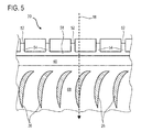
- the figure 5 shows an internal view of a portion of the inner wall 30. There is shown a series of stator vanes 26, and the primary flow 18. For the sake of clarity, the outer wall is not shown.
- the inner wall supports a plurality of stator vanes 26 of an annular row.
- the upstream edge 44 forms slots between the notches 52.
- the latter sink into the upstream edge 44 towards the blades 26, then extend in this same direction thanks to their grooves 54.
- These latter join in the annular channel 58, which is generally formed in the central position of the upstream bearing surface 46, and / or on the internal step of the inner wall 30.
- the blades of the blades 26 can be directly attached to the inner surface 68 of the ferrule. Alternatively, they may have platforms or bulbs welded into openings in the ferrule.
- the inner wall 30 may be an outer shell at the compressor inlet.
Landscapes
- Engineering & Computer Science (AREA)
- Chemical & Material Sciences (AREA)
- Combustion & Propulsion (AREA)
- Mechanical Engineering (AREA)
- General Engineering & Computer Science (AREA)
- Aviation & Aerospace Engineering (AREA)
- Physics & Mathematics (AREA)
- Thermal Sciences (AREA)
- Structures Of Non-Positive Displacement Pumps (AREA)
Abstract
Description
- L'invention a trait à bec de séparation dégivrant de turbomachine axiale. Plus précisément, l'invention concerne le dégivrage d'un bec de séparation par réinjection d'un gaz chaud à l'intérieur du bec. L'invention a également trait à une turbomachine axiale, notamment un turboréacteur d'avion ou un turbopropulseur d'aéronef.
- Un turbopropulseur multi-flux d'avion est conçu pour respecter l'environnement. Dans l'optique d'optimiser la poussée et le rendement, tout en réduisant les nuisances sonores, un turbopropulseur travaille avec plusieurs flux d'airs annulaires. Pour cela, le turbopropulseur sépare un flux entrant en un flux primaire et en un flux secondaire. Les flux sont séparés par un bec de séparation circulaire placé en amont du compresseur. A cet endroit, il forme l'entrée d'air du compresseur.
- L'air pénétrant dans la turbomachine reste à température atmosphérique au niveau du bec de séparation. Ces températures pouvant descendre à - 50°C en altitude, de la glace peut se former sur le bec avec l'humidité. En vol, cette glace peut s'étendre et s'accumuler jusqu'à former des blocs en tête d'aubes statoriques du compresseur. Ces blocs peuvent aussi modifier la géométrie du bec et influer sur le flux d'air entrant dans le compresseur, ce qui peut en dégrader le rendement.
- A force de se développer, les blocs peuvent devenir massifs puis se détacher en raison des vibrations de la turbomachine. Entraînés par le flux entrant, ces blocs peuvent être ingérés par le compresseur, risquant au passage de dégrader les aubes rotoriques. Cette ingestion est particulièrement pénalisante tant elle ne subit pas au préalable un passage dans la soufflante. Pour limiter cette formation de glace, les becs de séparation sont munis d'un dispositif de dégivrage.
- Le document
US 6,561,760 B2 divulgue un compresseur de turbomachine axiale muni d'un bec de séparation dégivrant. Ce dernier est réchauffé à l'aide d'une circulation d'air chaud prélevé dans un compresseur de la turbomachine. L'air chaud est injecté à l'intérieur du bec de séparation puis s'échappe en s'immisçant dans le crochet amont, entre la paroi externe du bec et la virole externe. Des gorges axiales sont ménagées dans la virole externe pour former un passage dans le crochet, si bien que l'écoulement dégivrant est optimisé. Toutefois, un tel bec de séparation reste coûteux en raison de l'agencement des interfaces. La géométrie des passages est complexe, ce qui nuit au fonctionnement puisque les tolérances de fabrication dégradent les conditions réelles de fonctionnement. - L'invention a pour objectif de résoudre au moins un des problèmes posés par l'art antérieur. Plus précisément, l'invention a pour objectif de simplifier un bec de séparation dégivrant. L'invention a également pour objectif d'alléger un bec de séparation.
- L'invention a pour objet un bec de séparation de turbomachine axiale, notamment de compresseur de turbomachine axiale, le bec comprenant :
- une paroi annulaire externe ; une paroi annulaire interne avec un bord amont circulaire lié à la paroi externe, la paroi interne étant configurée pour délimiter un flux annulaire interne séparé par le bec de séparation, notamment un flux primaire ; remarquable en ce que le bord amont de la paroi interne comprend au moins une encoche qui traverse radialement la paroi interne afin de permettre une circulation de fluide dégivrant au travers de la paroi interne.
- Selon un mode avantageux de l'invention, la paroi interne comprend au moins une rainure formée dans son épaisseur et qui prolonge axialement la ou chaque encoche.
- Selon un mode avantageux de l'invention, la ou chaque encoche présente une forme de lunule, éventuellement un profil en lunule.
- Selon un mode avantageux de l'invention, la paroi interne comprend une surface annulaire externe lisse qui délimite axialement la ou chaque encoche, éventuellement la paroi externe s'éloigne progressivement radialement vers l'extérieur de ladite surface externe vers l'aval.
- Selon un mode avantageux de l'invention, la paroi interne comprend une portée amont sur laquelle est formé son bord amont, et qui forme une augmentation de diamètre, préférentiellement la portée amont forme une marche annulaire.
- Selon un mode avantageux de l'invention, la paroi interne comprend une surface annulaire interne et un chenal annulaire interne formé sur ladite surface interne, ledit chenal annulaire délimitant axialement la ou chaque encoche et/ou étant en communication avec la ou chaque encoche.
- Selon un mode avantageux de l'invention, la paroi interne est une virole externe, et/ou supporte une rangée annulaire d'aubes s'étendant radialement vers l'intérieur depuis ladite paroi interne, et/ou supporte un joint annulaire interne, notamment une couche annulaire de matériau abradable.
- Selon un mode avantageux de l'invention, la paroi externe comprend au moins un passage en communication avec l'encoche, préférentiellement plusieurs passages chacun en communication avec une des encoches.
- Selon un mode avantageux de l'invention, le ou chaque passage est une gorge axiale, éventuellement inclinée par rapport à l'axe central du bec.
- Selon un mode avantageux de l'invention, le ou chaque passage est à distance axialement de la ou de chaque encoche de la paroi interne.
- Selon un mode avantageux de l'invention, la paroi externe comprend un crochet annulaire, le bord amont de la paroi interne étant fixé audit crochet annulaire, préférentiellement le crochet annulaire présente un creux annulaire tourné vers l'aval dans lequel est monté le bord amont de la paroi interne.
- Selon un mode avantageux de l'invention, le crochet annulaire forme l'extrémité amont de la paroi externe, préférentiellement le bec de séparation comprend un bord d'attaque circulaire formé sur le crochet annulaire.
- Selon un mode avantageux de l'invention, le bord amont affleure axialement la paroi externe, préférentiellement le bec comprend un jeu mécanique annulaire entre le bord amont et la paroi externe qui est inférieur à la profondeur de la ou de chaque encoche, et/ou inférieur égal à 5,00 mm, plus préférentiellement inférieur ou égal à 2,00 mm, éventuellement inférieur ou égal à 0,50 mm.
- Selon un mode avantageux de l'invention, la paroi externe comprend une portion annulaire interne et une portion annulaire externe entre lesquelles est intercalé le bord amont de la paroi interne, la portion interne étant plus épaisse radialement que la portion externe,
- Selon un mode avantageux de l'invention, la portion annulaire interne et la portion annulaire externe se chevauchent axialement, préférentiellement la portion externe est généralement d'épaisseur constante, et/ou la portion annulaire externe est la portion principale de la paroi externe.
- Selon un mode avantageux de l'invention, le bec comprend un espace annulaire en communication avec la ou chaque encoche, ledit espace étant délimité par la paroi interne et la paroi externe.
- Selon un mode avantageux de l'invention, la paroi interne et la paroi externe comprennent des brides annulaires de fixation fixées l'une à l'autre et qui sont disposées en aval de la ou de chaque encoche, lesdites brides délimitant éventuellement l'espace annulaire.
- Selon un mode avantageux de l'invention, le bec de séparation est dégivrant et/ou antigivre, notamment configuré pour permettre une circulation d'air chaud, et/ou pour réinjecter l'air dégivrant le flux interne.
- Selon un mode avantageux de l'invention, la paroi annulaire externe est destinée à guider un flux annulaire externe à l'intérieur de la turbomachine, notamment un flux secondaire.
- Selon un mode avantageux de l'invention, la paroi annulaire interne est à l'intérieur de la paroi externe, lesdites parois étant coaxiales.
- Selon un mode avantageux de l'invention, le ou chaque passage est en communication avec le chenal annulaire, et/ou le chenal annulaire est intercalé axialement et/ou radialement entre les passages et les encoches.
- Selon un mode avantageux de l'invention, le bord d'attaque sépare un flux amont en un flux externe et en le flux interne qui s'écoulent axialement.
- Selon un mode avantageux de l'invention, la paroi externe présente une épaisseur variable, et éventuellement une épaisseur maximale en amont.
- Selon un mode avantageux de l'invention, la paroi interne et/ou la paroi externe sont chacune des éléments monoblocs, préférentiellement venus de matière, et/ou elles peuvent être métalliques, et les passages peuvent y être usinés.
- L'invention a également pour objet une virole externe de turbomachine, notamment de compresseur de turbomachine axiale, la virole comprenant une rangée annulaire d'aubes, ou une zone annulaire de réception d'aubes éventuellement formée par une rangée annulaire d'ouvertures de réception de plateformes d'aubes, et un bord amont circulaire, remarquable en ce que le bord amont de la virole externe comprend au moins une encoche qui le traverse radialement la afin de permettre une circulation de fluide dégivrant au travers dudit bord.
- L'invention a également pour objet un bec de séparation avec une virole externe apte à recevoir une rangée annulaire d'aubes statoriques, la virole externe présentant un bord amont circulaire fixée audit bec, remarquable en ce que le bord amont comprend au moins une encoche qui traverse radialement la virole externe afin de permettre une circulation de fluide dégivrant au travers de la virole externe. Selon cette approche, le bec de séparation est ici assimilé à la paroi externe présentée ci-dessus.
- L'invention a également pour objet un compresseur de turbomachine comprenant un bec de séparation, remarquable en ce que le bec est conforme à l'invention.
- L'invention a également pour objet une turbomachine comprenant un bec de séparation, remarquable en ce que le bec est conforme à l'invention.
- Selon un mode avantageux de l'invention, comprend un compresseur, notamment un compresseur haute pression, et un conduit de prélèvement d'air en communication avec ledit compresseur et la ou chaque encoche afin d'alimenter en air dégivrant le bec de séparation.
- Selon un mode avantageux de l'invention, la turbomachine comprend un compresseur, notamment un compresseur basse pression, le bec de séparation formant l'entrée dudit compresseur.
- De manière générale, les modes avantageux de chaque objet de l'invention sont également applicables aux autres objets de l'invention. Dans la mesure du possible, chaque objet de l'invention est combinable aux autres objets.
- L'invention simplifie le bec de séparation tout en formant une antichambre pour le gaz chaud. Le nombre de composants est réduit, et la forme de la virole permet de gérer l'écoulement grâce au calibrage des encoches. En effet, leur section de passage limite l'écoulement qui les traverse. Par ailleurs, cette solution permet de réduire la masse puisque la paroi extérieure peut rester d'épaisseur constante au-dessus du bord amont de la paroi interne.
- L'agencement rend le bec économique. En effet, les encoches sont des formes simples à réaliser ; sur des longueurs réduites. Lorsqu'elles sont usinées, la matière à enlever est limitée. La zone où elles sont taillées est facilement accessible et présente une raideur adaptée aux efforts de coupe. L'effet de la dilation sur la section passante des encoches est moindre. L'agencement permet de conserver une efficacité de dégivrage indépendamment de la température, ce qui est particulièrement important pour des parois susceptibles de givrer.
- La présente architecture optimise le fonctionnement puisque le réchauffement est permis en tout point et de manière homogène. L'épaisseur à l'intérieur de la paroi externe est compensée par les gorges qui y sont formées. Ainsi, la température de l'air d'apport peut être réduite tout en maintenant la sécurité.
-
- La
figure 1 représente une turbomachine axiale selon l'invention. - La
figure 2 est un schéma d'un compresseur de turbomachine selon l'invention. - La
figure 3 illustre un bec de séparation selon l'invention. - La
figure 4 est un agrandissement de la pointe amont du bec de séparation selon l'invention. - La
figure 5 montre une paroi interne selon l'invention observée depuis l'intérieur. - Dans la description qui va suivre, les termes intérieur ou interne et extérieur ou externe renvoient à un positionnement par rapport à l'axe de rotation d'une turbomachine axiale. La direction axiale correspond à la direction le long de l'axe de rotation de la turbomachine. La direction radiale est perpendiculaire à l'axe de rotation. L'amont et l'aval sont en référence au sens d'écoulement principal du flux dans la turbomachine.
- La
figure 1 représente de manière simplifiée une turbomachine axiale. Il s'agit dans ce cas précis d'un turboréacteur double-flux. Le turboréacteur 2 comprend un premier niveau de compression, dit compresseur basse-pression 4, un deuxième niveau de compression, dit compresseur haute-pression 6, une chambre de combustion 8 et un ou plusieurs niveaux de turbines 10. En fonctionnement, la puissance mécanique de la turbine 10 transmise via l'arbre central jusqu'au rotor 12 met en mouvement les deux compresseurs 4 et 6. Ces derniers comportent plusieurs rangées d'aubes de rotor associées à des rangées d'aubes de stators. La rotation du rotor autour de son axe de rotation 14 permet ainsi de générer un débit d'air et de comprimer progressivement ce dernier jusqu'à l'entrée de la chambre de combustion 8. Des moyens de démultiplication peuvent augmenter la vitesse de rotation transmise aux compresseurs. - Un ventilateur d'entrée communément désigné fan ou soufflante 16 est couplé au rotor 12 et génère un flux d'air qui se divise en un flux primaire 18 traversant les différents niveaux sus mentionnés de la turbomachine, et un flux secondaire 20 traversant un conduit annulaire (partiellement représenté) le long de la machine pour ensuite rejoindre le flux primaire en sortie de turbine. Le flux secondaire peut être accéléré de sorte à générer une réaction de poussée. Les flux primaire 18 et secondaire 20 sont des flux annulaires, ils sont canalisés par le carter de la turbomachine. Chacun d'eux s'écoule axialement. A cet effet, le carter présente des parois cylindriques ou viroles qui peuvent être internes et externes.
- La
figure 2 est une vue en coupe d'un compresseur d'une turbomachine axiale telle que celle de lafigure 1 . Le compresseur peut être un compresseur basse-pression 4. On peut y observer une partie du fan 16 et le bec de séparation 22 du flux primaire 18 et du flux secondaire 20. Le rotor 12 comprend plusieurs rangées d'aubes rotoriques 24, en l'occurrence trois. - Le compresseur basse pression 4 comprend plusieurs redresseurs, en l'occurrence quatre, qui contiennent chacun une rangée d'aubes statoriques 26. Les redresseurs sont associés au fan 16 ou à une rangée d'aubes rotoriques pour redresser le flux d'air, de sorte à convertir la vitesse du flux en pression statique. Les aubes statoriques 26 s'étendent essentiellement radialement depuis un carter extérieur ou une virole extérieure, et peuvent y être fixées et immobilisées à l'aide d'axes. Alternativement, elles peuvent être soudées par faisceau laser. Certaines aubes peuvent être différentes du reste des aubes de leur rangée.
- La
figure 3 représente le bec de séparation 22 d'un flux entrant dans la turbomachine. Le bec de séparation 22 peut correspondre à celui qui est en entrée du compresseur basse pression illustré enfigure 2 . - Le bec de séparation 22 comprend une paroi annulaire externe 28 et une paroi annulaire interne 30. Ces parois (28 ; 30) sont concentriques, elles guident et délimitent le flux secondaire 20 et le flux primaire 18 respectivement. Plus exactement, ces flux (18 ; 20) sont séparés par le bord d'attaque circulaire 32, ou bord de séparation, qui forme l'extrémité amont dudit bec 22. Il reçoit en premier les ingestions.
- Les parois (28 ; 30) peuvent comprendre des brides annulaires de fixation 34, éventuellement fixées l'une à l'autre à l'aide d'axes de fixation (non représentés) répartis angulairement. Elles peuvent former une cloison étanche entre les parois (28 ; 30). En combinaison, les parois (28 ; 30) délimitent un espace annulaire 36 qui est fermé en aval grâce aux brides de fixation 34. Cet espace annulaire 36 est alimenté en fluide de dégivrant, en l'occurrence du gaz chaud. L'écoulement 38 ou la présence de gaz chaud permet de dégivrer et/ou de prévenir l'accrétion de glace sur le bec de séparation 22, que ce soit au contact du flux primaire 18 ou du flux secondaire 20.
- Le bec de séparation 22 peut comprendre un conduit d'alimentation 40 en air chaud. Il peut être un conduit de prélèvement 40 d'air d'un compresseur de la turbomachine, par exemple le compresseur haute pression. Le prélèvement est avantageusement en aval dudit compresseur, optionnellement au niveau de son dernier étage de compression. Le conduit 40 est en communication de l'espace annulaire interne 36 du bec, et donc du passage de réinjection de fluide dégivrant dans le compresseur. Le passage peut former un échappement.
- La paroi externe 28 peut comprendre un crochet annulaire 42 formant son extrémité amont, et notamment le bord d'attaque 32. Le bord amont 44 de la paroi interne 30 est fixé audit crochet annulaire 42, ce qui permet de maintenir l'extrémité amont de la paroi interne 30 qui est en porte-à-faux. Un centrage et une mise en concordance des surfaces délimitant le flux primaire 18 sont également assurés. Le crochet annulaire 42 peut présenter un creux annulaire ouvert vers l'aval. Le creux reçoit le bord amont 44 de la paroi interne 30 pour l'y lier.
- La paroi interne 30 présente généralement une configuration en plusieurs tronçons, notamment de différents diamètres. Elle comprend une portée amont 46 de montage avec le bord amont et est en contact de la paroi externe 28. La portée amont 46 forme une augmentation de diamètre et présente deux marches annulaires, une interne et une externe. Un tronçon principal 48, ou tronçon central, peut supporter une rangée annulaire d'aubes statorique 26. Un tronçon aval peut accueillir un joint annulaire interne 50, notamment une couche annulaire de matériau abradable 50. Une telle couche 50 forme un joint d'étanchéité apte à s'effriter en cas de contact avec une aube rotorique lors du fonctionnement de la turbomachine.
- La
figure 4 est un agrandissement du bec de séparation 22 au niveau du bord d'attaque 32. Il y est représenté la paroi interne 30 et la paroi externe 28, et en particulier leur interface aménagée pour permettre l'écoulement dégivrant 38. - Le passage permettant l'écoulement du fluide dégivrant 38 présente au moins une encoche 52 formée dans le bord amont 44 de la paroi interne 30. Préférentiellement, le bord amont 44 présente une pluralité d'encoches 52 réparties sur son périmètre qui sont en communication avec l'espace annulaire 36 recevant le fluide dégivrant. Chaque encoche 52 forme un redan sur le bord 44, une brèche pénétrant axialement dans la paroi interne 30. Chaque encoche 52 traverse radialement le bord amont 44, elle facilite le passage de l'extérieur vers l'intérieur de la paroi interne 30. En l'occurrence, les encoches 52 permettent l'écoulement du fluide 38 dégivrant vers l'intérieur du bec 22, vers l'intérieur de la surface interne de la paroi interne 30, ce qui optimise le dégivrage. Les encoches 52 peuvent chacune avoir une forme courbe, telle une lunule. Par lunule, on peut entendre, la surface interne d'un premier disque à laquelle est retirée la surface d'un autre disque coupant le premier disque en deux points.
- Chaque encoche 52 est prolongée par une rainure 54 taillée dans l'épaisseur radiale de la paroi interne 30. Elle prolonge axialement une encoche 52 et suit la surface externe de la paroi externe 28 qui est en regard. La réunion des parois permet de former des conduits avec un profil généralement fermé pour canaliser et maîtriser l'écoulement dégivrant 38.
- La paroi interne 30 comprend une surface annulaire externe 56 lisse qui délimite axialement les encoches 52, et qui se prolonge en amont entre les encoches 52. La paroi externe 28 s'éloigne progressivement vers l'extérieur radialement de ladite surface externe 56 vers l'aval. Ainsi, l'espace annulaire 36 s'étend jusqu'au bord amont 44 de la paroi interne 30, favorisant l'apport de calories jusqu'au bord d'attaque 32.
- La paroi interne 32 comprend éventuellement une surface interne avec un chenal annulaire interne 58 s'enfonçant radialement vers l'extérieur dans l'épaisseur de la paroi interne 30. Ce chenal annulaire 58 communique avec chaque encoche 52 en les délimitant. Plus précisément, chaque rainure axiale 54 débouche sur le chenal annulaire 58 qui permet de les réunir.
- La paroi externe 28 comprend au moins un passage 60 en communication avec une encoche 52. Préférentiellement elle comprend plusieurs passages 60 qui sont chacun mis en correspondance avec au moins une encoche 52 pour permettre un passage de l'une à l'autre. Par exemple, un passage 60 peut être en face d'au moins trois encoches 52 et communiquer avec elles. Le ou chaque passage 60 est une gorge axiale dont le fond est éventuellement inclinée par rapport à l'axe de rotation de la turbomachine 14, cet axe coïncidant éventuellement avec l'axe central 14 du bec 2. Les passages 60 inclinés permettent une meilleure réinjection de l'écoulement 38 dans le flux primaire. La formation de tourbillons est réduite et le rendement de la turbomachine est préservée. Alternativement, un ou plusieurs passages sont des orifices traversant la paroi externe.
- Les passages 60 et les encoches 52 peuvent communiquer via le chenal annulaire 58, ce qui autorise des écarts de positionnement. Les passages 60 et les encoches 52 peuvent ainsi être distantes axialement et angulairement l'une de l'autre puisque le chenal est intercalé à leur interface. Cependant, la présence du chenal est optionnelle puisque les passages et les encoches peuvent communiquer directement.
- Le crochet annulaire 42 de la paroi externe 28 comprend une portion annulaire interne 62 et une portion annulaire externe 64 qui occupent un même tronçon axial. Entre elles est glissé le bord amont 44 de la paroi interne 30. La portion interne 62 est plus épaisse radialement que la portion externe 64 pour offrir davantage de résistance puisque c'est elle qui soutient la paroi interne 30. La portion externe 64 est généralement d'épaisseur constante, elle forme la portion principale de la paroi externe 28 en raison de sa longueur axiale. Le bord amont 44 de la paroi interne 30 épouse axialement le crochet annulaire 42. Ce bord 44 en affleure le fond. Toutefois, un jeu mécanique annulaire 66 les sépare. Ce jeu 66 est inférieur à la profondeur axiale des encoches 52. Il peut être inférieur ou égal à 0,05 mm.
- La
figure 5 montre une vue interne d'une portion de la paroi interne 30. Il y est représenté une série d'aubes statoriques 26, ainsi que le flux primaire 18. Par soucis de clarté, la paroi externe n'est pas représentée. - La paroi interne supporte plusieurs aubes statoriques 26 d'une rangée annulaire. Le bord amont 44 forme des créneaux entre les encoches 52. Ces dernières s'enfoncent dans le bord amont 44 vers les aubes 26, puis se prolongent dans cette même direction grâce à leurs rainures 54. Ces dernières se rejoignent dans le chenal annulaire 58, qui est généralement formé en position centrale de la portée amont 46, et/ou sur la marche interne de la paroi interne 30.
- Les pales des aubes 26 peuvent être directement fixées à surface interne 68 de la virole. Alternativement, elles peuvent présenter des plateformes ou des bulbes soudés dans des ouvertures ménagées dans la virole. La paroi interne 30 peut être une virole externe en entrée de compresseur.
Claims (15)
- Bec de séparation (22) de turbomachine axiale (2), notamment de compresseur (4 ; 6) de turbomachine axiale (2), le bec (22) comprenant :une paroi annulaire externe (28);une paroi annulaire interne (30) avec un bord amont circulaire (44) lié à la paroi externe (28), la paroi interne (30) étant configurée pour délimiter un flux annulaire interne (18) séparé par le bec de séparation (22), notamment un flux primaire ;caractérisé en ce quele bord amont (44) de la paroi interne (30) comprend au moins une encoche (52) qui traverse radialement la paroi interne (30) afin de permettre une circulation de fluide dégivrant (38) au travers de la paroi interne (30).
- Bec de séparation (22) selon la revendication 1, caractérisé en ce que la paroi interne (30) comprend au moins une rainure formée dans son épaisseur et qui prolonge axialement la ou chaque encoche (52).
- Bec de séparation (22) selon l'une des revendications 1 à 2, caractérisé en ce que la ou chaque encoche (52) présente une forme de lunule, éventuellement un profil en lunule.
- Bec de séparation (22) selon l'une des revendications 1 à 3, caractérisé en ce que la paroi interne (30) comprend une surface annulaire externe (56) lisse qui délimite axialement la ou chaque encoche (52), éventuellement la paroi externe (28) s'éloigne progressivement radialement vers l'extérieur de ladite surface externe (56) vers l'aval.
- Bec de séparation (22) selon l'une des revendications 1 à 4, caractérisé en ce que la paroi interne (30) comprend une portée amont (46) sur laquelle est formé son bord amont (44), et qui forme une augmentation de diamètre, préférentiellement la portée amont (44) forme une marche annulaire.
- Bec de séparation (22) selon l'une des revendications 1 à 5, caractérisé en ce que la paroi interne (30) comprend une surface annulaire interne (66) et un chenal annulaire (58) interne formé sur ladite surface interne, ledit chenal annulaire (58) délimitant axialement la ou chaque encoche (52) et/ou étant en communication avec la ou chaque encoche (52).
- Bec de séparation (22) selon l'une des revendications 1 à 6, caractérisé en ce que la paroi interne (30) est une virole externe, et/ou supporte une rangée annulaire d'aubes (26) s'étendant radialement vers l'intérieur depuis ladite paroi interne (30), et/ou supporte un joint annulaire interne, notamment une couche annulaire de matériau abradable (50).
- Bec de séparation (22) selon l'une des revendications 1 à 7, caractérisé en ce que la paroi externe (28) comprend au moins un passage (60) en communication avec l'encoche (52), préférentiellement plusieurs passages (60) chacun en communication avec une des encoches (52).
- Bec de séparation (22) selon l'une des revendications 1 à 8, caractérisé en ce que la paroi externe (28) comprend un crochet annulaire (42), le bord amont (44) de la paroi interne (30) étant fixé audit crochet annulaire (42), préférentiellement le crochet annulaire (42) présente un creux annulaire tourné vers l'aval dans lequel est monté le bord amont (44) de la paroi interne (30).
- Bec de séparation (22) selon la revendication 9, caractérisé en ce que le crochet annulaire (42) forme l'extrémité amont de la paroi externe (28), préférentiellement le bec de séparation (22) comprend un bord d'attaque (32) circulaire formé sur le crochet annulaire (42).
- Bec de séparation (22) selon l'une des revendications 1 à 10, caractérisé en ce que le bord amont (44) affleure axialement la paroi externe (28), préférentiellement le bec (22) comprend un jeu mécanique annulaire (66) entre le bord amont (44) et la paroi externe (28) qui est inférieur à la profondeur de la ou de chaque encoche (52), et/ou inférieur égal à 5,00 mm, plus préférentiellement inférieur ou égal à 2,00 mm, éventuellement inférieur ou égal à 0,50 mm.
- Bec de séparation (22) selon l'une des revendications 1 à 11, caractérisé en ce que la paroi externe (28) comprend une portion annulaire interne (62) et une portion annulaire externe (64) entre lesquelles est intercalé le bord amont (44) de la paroi interne (30), la portion interne (62) étant plus épaisse radialement que la portion externe (64).
- Bec de séparation (22) selon l'une des revendications 1 à 12, caractérisé en ce qu'il comprend un espace annulaire (36) en communication avec la ou chaque encoche (52), ledit espace (36) étant délimité par la paroi interne (30) et la paroi externe (28).
- Bec de séparation (22) selon l'une des revendications 1 à 13, caractérisé en ce que la paroi interne (30) et la paroi externe (28) comprennent des brides annulaires de fixation (34) fixées l'une à l'autre et qui sont disposées en aval de la ou de chaque encoche (52), lesdites brides (34) délimitant éventuellement l'espace annulaire (36).
- Turbomachine (2) comprenant un bec de séparation (22), caractérisée en ce que le bec (22) est conforme à l'une des revendications 1 à 14, préférentiellement la turbomachine comprend un compresseur (4 ; 6), notamment un compresseur haute pression (6), et un conduit de prélèvement d'air (40) en communication avec ledit compresseur (6) et la ou chaque encoche (52) afin d'alimenter en air dégivrant le bec de séparation (22).
Applications Claiming Priority (1)
| Application Number | Priority Date | Filing Date | Title |
|---|---|---|---|
| BE2015/5508A BE1023354B1 (fr) | 2015-08-13 | 2015-08-13 | Bec de separation degivrant de compresseur de turbomachine axiale |
Publications (2)
| Publication Number | Publication Date |
|---|---|
| EP3130765A1 true EP3130765A1 (fr) | 2017-02-15 |
| EP3130765B1 EP3130765B1 (fr) | 2018-05-16 |
Family
ID=54072633
Family Applications (1)
| Application Number | Title | Priority Date | Filing Date |
|---|---|---|---|
| EP16183309.0A Active EP3130765B1 (fr) | 2015-08-13 | 2016-08-09 | Bec de separation degivrant de compresseur de turbomachine axiale |
Country Status (4)
| Country | Link |
|---|---|
| US (1) | US10017259B2 (fr) |
| EP (1) | EP3130765B1 (fr) |
| CN (1) | CN106438497B (fr) |
| BE (1) | BE1023354B1 (fr) |
Cited By (1)
| Publication number | Priority date | Publication date | Assignee | Title |
|---|---|---|---|---|
| EP3409906A1 (fr) | 2017-05-31 | 2018-12-05 | Safran Aero Boosters SA | Dégivrage d'un bord d'attaque de turbomachine par des moyens pneumatiques |
Families Citing this family (10)
| Publication number | Priority date | Publication date | Assignee | Title |
|---|---|---|---|---|
| WO2017017378A1 (fr) * | 2015-07-30 | 2017-02-02 | Safran Aircraft Engines | Systeme d'antigivrage d'une aube de turbomachine. |
| FR3047042B1 (fr) * | 2016-01-22 | 2018-02-16 | Safran Aircraft Engines | Dispositif de degivrage d'un bec de separation et d'aubes directrices d'entree d'une turbomachine aeronautique |
| US10533497B2 (en) * | 2016-04-18 | 2020-01-14 | United Technologies Corporation | Short inlet with integrated liner anti-icing |
| US10569888B2 (en) * | 2016-12-20 | 2020-02-25 | Airbus Operations Gmbh | Leading edge ice-protection system |
| US11053848B2 (en) * | 2018-01-24 | 2021-07-06 | General Electric Company | Additively manufactured booster splitter with integral heating passageways |
| RU2712103C1 (ru) * | 2019-04-12 | 2020-01-24 | Федеральное государственное унитарное предприятие "Центральный институт авиационного моторостроения имени П.И. Баранова" | Способ управления противообледенительной системой турбореактивного двухконтурного двигателя |
| FR3095230B1 (fr) * | 2019-04-16 | 2021-03-19 | Safran Aircraft Engines | Dispositif de degivrage |
| US20210163141A1 (en) * | 2019-11-28 | 2021-06-03 | Pratt & Whitney Canada Corp. | Gas turbine engine, nacelle thereof, and associated method of operating a gas turbine engine |
| CN111577463B (zh) * | 2020-05-25 | 2021-08-17 | 中国航发沈阳发动机研究所 | 一种发动机进气机匣结构 |
| CN113086211B (zh) * | 2021-06-07 | 2021-10-12 | 中国空气动力研究与发展中心低速空气动力研究所 | 一种电热分割区域机械除冰装置和除冰方法 |
Citations (4)
| Publication number | Priority date | Publication date | Assignee | Title |
|---|---|---|---|---|
| US20030035719A1 (en) * | 2001-08-17 | 2003-02-20 | Wadia Aspi Rustom | Booster compressor deicer |
| FR2999235A1 (fr) * | 2012-12-11 | 2014-06-13 | Snecma | Dispositif de degivrage d'un bord d'attaque de turbomachine par encoches inclinees |
| WO2014182289A1 (fr) * | 2013-05-07 | 2014-11-13 | General Electric Company | Nez de séparateur antigivre |
| EP2821597A1 (fr) * | 2013-07-05 | 2015-01-07 | Techspace Aero S.A. | Bec de séparation avec tôle formant une surface de guidage du flux et un canal de dégivrage |
Family Cites Families (3)
| Publication number | Priority date | Publication date | Assignee | Title |
|---|---|---|---|---|
| US8192147B2 (en) * | 2007-12-14 | 2012-06-05 | United Technologies Corporation | Nacelle assembly having inlet bleed |
| US9309781B2 (en) * | 2011-01-31 | 2016-04-12 | General Electric Company | Heated booster splitter plenum |
| EP2740905B1 (fr) * | 2012-12-07 | 2020-03-18 | Safran Aero Boosters SA | Bec de séparation d'une turbomachine axiale, compresseur et turbomachine axiale associés |
-
2015
- 2015-08-13 BE BE2015/5508A patent/BE1023354B1/fr active
-
2016
- 2016-08-09 EP EP16183309.0A patent/EP3130765B1/fr active Active
- 2016-08-10 US US15/233,340 patent/US10017259B2/en active Active
- 2016-08-15 CN CN201610670154.0A patent/CN106438497B/zh active Active
Patent Citations (5)
| Publication number | Priority date | Publication date | Assignee | Title |
|---|---|---|---|---|
| US20030035719A1 (en) * | 2001-08-17 | 2003-02-20 | Wadia Aspi Rustom | Booster compressor deicer |
| US6561760B2 (en) | 2001-08-17 | 2003-05-13 | General Electric Company | Booster compressor deicer |
| FR2999235A1 (fr) * | 2012-12-11 | 2014-06-13 | Snecma | Dispositif de degivrage d'un bord d'attaque de turbomachine par encoches inclinees |
| WO2014182289A1 (fr) * | 2013-05-07 | 2014-11-13 | General Electric Company | Nez de séparateur antigivre |
| EP2821597A1 (fr) * | 2013-07-05 | 2015-01-07 | Techspace Aero S.A. | Bec de séparation avec tôle formant une surface de guidage du flux et un canal de dégivrage |
Cited By (2)
| Publication number | Priority date | Publication date | Assignee | Title |
|---|---|---|---|---|
| EP3409906A1 (fr) | 2017-05-31 | 2018-12-05 | Safran Aero Boosters SA | Dégivrage d'un bord d'attaque de turbomachine par des moyens pneumatiques |
| US10773810B2 (en) | 2017-05-31 | 2020-09-15 | Safran Aero Boosters Sa | Turbofan engine de-icing compressor and de-icing process |
Also Published As
| Publication number | Publication date |
|---|---|
| CN106438497B (zh) | 2019-02-15 |
| CN106438497A (zh) | 2017-02-22 |
| EP3130765B1 (fr) | 2018-05-16 |
| US20170043877A1 (en) | 2017-02-16 |
| BE1023354A1 (fr) | 2017-02-13 |
| BE1023354B1 (fr) | 2017-02-13 |
| US10017259B2 (en) | 2018-07-10 |
Similar Documents
| Publication | Publication Date | Title |
|---|---|---|
| EP3130765B1 (fr) | Bec de separation degivrant de compresseur de turbomachine axiale | |
| EP2821597B1 (fr) | Bec de séparation avec tôle formant une surface de guidage du flux et un canal de dégivrage | |
| EP3156615B1 (fr) | Dispositif degivrant de bec de separation de compresseur de turbomachine axiale | |
| EP1503061B1 (fr) | Procédé de refroidissement, par air refroidi en partie dans un échangeur externe, des parties chaudes d'un turboréacteur, et turboréacteur ainsi refroidi. | |
| EP2440746B1 (fr) | Turbomachine comprenant des moyens ameliores de reglage du debit d'un flux d'air de refroidissement preleve en sortie de compresseur haute pression | |
| EP3112694B1 (fr) | Tambour perforé de compresseur de turbomachine axiale | |
| EP3012416B1 (fr) | Bec de séparation et turbomachine associée | |
| EP2801702B1 (fr) | Virole interne de redresseur de turbomachine avec joint abradable | |
| EP3312391B1 (fr) | Bec dégivrant de compresseur de turbomachine axiale | |
| EP3580443B1 (fr) | Turboréacteur a double flux comprenant une veine intermédiaire dédiée a l'alimentation en air par des bras radiaux d'un carter d'échappement de ce turboréacteur | |
| FR3051016A1 (fr) | Dispositif de degivrage d'un bec de separation de turbomachine aeronautique | |
| EP2803822B1 (fr) | Système de prélèvement d'air de turbomachine axiale | |
| EP1911936B1 (fr) | Canal de transition entre deux étages de turbine | |
| WO2020084221A1 (fr) | Module electrique de soufflante d'aeronef comportant des aubes a fixation perfectionnee | |
| FR2955152A1 (fr) | Turbomachine a circulation de flux d'air de purge amelioree | |
| FR3087824A1 (fr) | Module electrique de soufflante d'aeronef comportant des aubes a fixation amelioree | |
| BE1024605A1 (fr) | Carter avec bras aspirant pour turbomachine axiale | |
| EP3290657B1 (fr) | Stator à aubes ajustables pour compresseur de turbomachine axiale | |
| BE1026063B1 (fr) | Aube motrice de systeme a calage variable de compresseur pour turbomachine | |
| FR3038655A1 (fr) | Ensemble comprenant un carter rainure et des moyens de refroidissement du carter, turbine comprenant ledit ensemble, et turbomachine comprenant ladite turbine | |
| FR3107312A1 (fr) | Ensemble rotatif pour turbomachine | |
| FR3131939A1 (fr) | Bec de séparation de turbomachine axiale comprenant un passage de débit d’air de dégivrage s’étandant jusqu’au redresseur | |
| FR3095229A1 (fr) | Ensemble pour flux primaire de turbomachine aéronautique, turbomachine munie de celui-ci |
Legal Events
| Date | Code | Title | Description |
|---|---|---|---|
| PUAI | Public reference made under article 153(3) epc to a published international application that has entered the european phase |
Free format text: ORIGINAL CODE: 0009012 |
|
| AK | Designated contracting states |
Kind code of ref document: A1 Designated state(s): AL AT BE BG CH CY CZ DE DK EE ES FI FR GB GR HR HU IE IS IT LI LT LU LV MC MK MT NL NO PL PT RO RS SE SI SK SM TR |
|
| AX | Request for extension of the european patent |
Extension state: BA ME |
|
| 17P | Request for examination filed |
Effective date: 20170726 |
|
| RBV | Designated contracting states (corrected) |
Designated state(s): AL AT BE BG CH CY CZ DE DK EE ES FI FR GB GR HR HU IE IS IT LI LT LU LV MC MK MT NL NO PL PT RO RS SE SI SK SM TR |
|
| GRAP | Despatch of communication of intention to grant a patent |
Free format text: ORIGINAL CODE: EPIDOSNIGR1 |
|
| RIC1 | Information provided on ipc code assigned before grant |
Ipc: F02C 7/047 20060101ALI20171109BHEP Ipc: F01D 25/02 20060101AFI20171109BHEP |
|
| INTG | Intention to grant announced |
Effective date: 20171123 |
|
| GRAS | Grant fee paid |
Free format text: ORIGINAL CODE: EPIDOSNIGR3 |
|
| GRAA | (expected) grant |
Free format text: ORIGINAL CODE: 0009210 |
|
| AK | Designated contracting states |
Kind code of ref document: B1 Designated state(s): AL AT BE BG CH CY CZ DE DK EE ES FI FR GB GR HR HU IE IS IT LI LT LU LV MC MK MT NL NO PL PT RO RS SE SI SK SM TR |
|
| REG | Reference to a national code |
Ref country code: GB Ref legal event code: FG4D Free format text: NOT ENGLISH |
|
| REG | Reference to a national code |
Ref country code: CH Ref legal event code: EP |
|
| REG | Reference to a national code |
Ref country code: IE Ref legal event code: FG4D Free format text: LANGUAGE OF EP DOCUMENT: FRENCH |
|
| REG | Reference to a national code |
Ref country code: DE Ref legal event code: R096 Ref document number: 602016003088 Country of ref document: DE |
|
| REG | Reference to a national code |
Ref country code: AT Ref legal event code: REF Ref document number: 999775 Country of ref document: AT Kind code of ref document: T Effective date: 20180615 |
|
| REG | Reference to a national code |
Ref country code: FR Ref legal event code: PLFP Year of fee payment: 3 |
|
| REG | Reference to a national code |
Ref country code: NL Ref legal event code: MP Effective date: 20180516 |
|
| REG | Reference to a national code |
Ref country code: LT Ref legal event code: MG4D |
|
| PG25 | Lapsed in a contracting state [announced via postgrant information from national office to epo] |
Ref country code: ES Free format text: LAPSE BECAUSE OF FAILURE TO SUBMIT A TRANSLATION OF THE DESCRIPTION OR TO PAY THE FEE WITHIN THE PRESCRIBED TIME-LIMIT Effective date: 20180516 Ref country code: LT Free format text: LAPSE BECAUSE OF FAILURE TO SUBMIT A TRANSLATION OF THE DESCRIPTION OR TO PAY THE FEE WITHIN THE PRESCRIBED TIME-LIMIT Effective date: 20180516 Ref country code: NO Free format text: LAPSE BECAUSE OF FAILURE TO SUBMIT A TRANSLATION OF THE DESCRIPTION OR TO PAY THE FEE WITHIN THE PRESCRIBED TIME-LIMIT Effective date: 20180816 Ref country code: SE Free format text: LAPSE BECAUSE OF FAILURE TO SUBMIT A TRANSLATION OF THE DESCRIPTION OR TO PAY THE FEE WITHIN THE PRESCRIBED TIME-LIMIT Effective date: 20180516 Ref country code: FI Free format text: LAPSE BECAUSE OF FAILURE TO SUBMIT A TRANSLATION OF THE DESCRIPTION OR TO PAY THE FEE WITHIN THE PRESCRIBED TIME-LIMIT Effective date: 20180516 Ref country code: BG Free format text: LAPSE BECAUSE OF FAILURE TO SUBMIT A TRANSLATION OF THE DESCRIPTION OR TO PAY THE FEE WITHIN THE PRESCRIBED TIME-LIMIT Effective date: 20180816 |
|
| PG25 | Lapsed in a contracting state [announced via postgrant information from national office to epo] |
Ref country code: GR Free format text: LAPSE BECAUSE OF FAILURE TO SUBMIT A TRANSLATION OF THE DESCRIPTION OR TO PAY THE FEE WITHIN THE PRESCRIBED TIME-LIMIT Effective date: 20180817 Ref country code: RS Free format text: LAPSE BECAUSE OF FAILURE TO SUBMIT A TRANSLATION OF THE DESCRIPTION OR TO PAY THE FEE WITHIN THE PRESCRIBED TIME-LIMIT Effective date: 20180516 Ref country code: LV Free format text: LAPSE BECAUSE OF FAILURE TO SUBMIT A TRANSLATION OF THE DESCRIPTION OR TO PAY THE FEE WITHIN THE PRESCRIBED TIME-LIMIT Effective date: 20180516 Ref country code: NL Free format text: LAPSE BECAUSE OF FAILURE TO SUBMIT A TRANSLATION OF THE DESCRIPTION OR TO PAY THE FEE WITHIN THE PRESCRIBED TIME-LIMIT Effective date: 20180516 Ref country code: HR Free format text: LAPSE BECAUSE OF FAILURE TO SUBMIT A TRANSLATION OF THE DESCRIPTION OR TO PAY THE FEE WITHIN THE PRESCRIBED TIME-LIMIT Effective date: 20180516 |
|
| REG | Reference to a national code |
Ref country code: AT Ref legal event code: MK05 Ref document number: 999775 Country of ref document: AT Kind code of ref document: T Effective date: 20180516 |
|
| PG25 | Lapsed in a contracting state [announced via postgrant information from national office to epo] |
Ref country code: CZ Free format text: LAPSE BECAUSE OF FAILURE TO SUBMIT A TRANSLATION OF THE DESCRIPTION OR TO PAY THE FEE WITHIN THE PRESCRIBED TIME-LIMIT Effective date: 20180516 Ref country code: SK Free format text: LAPSE BECAUSE OF FAILURE TO SUBMIT A TRANSLATION OF THE DESCRIPTION OR TO PAY THE FEE WITHIN THE PRESCRIBED TIME-LIMIT Effective date: 20180516 Ref country code: AT Free format text: LAPSE BECAUSE OF FAILURE TO SUBMIT A TRANSLATION OF THE DESCRIPTION OR TO PAY THE FEE WITHIN THE PRESCRIBED TIME-LIMIT Effective date: 20180516 Ref country code: PL Free format text: LAPSE BECAUSE OF FAILURE TO SUBMIT A TRANSLATION OF THE DESCRIPTION OR TO PAY THE FEE WITHIN THE PRESCRIBED TIME-LIMIT Effective date: 20180516 Ref country code: DK Free format text: LAPSE BECAUSE OF FAILURE TO SUBMIT A TRANSLATION OF THE DESCRIPTION OR TO PAY THE FEE WITHIN THE PRESCRIBED TIME-LIMIT Effective date: 20180516 Ref country code: EE Free format text: LAPSE BECAUSE OF FAILURE TO SUBMIT A TRANSLATION OF THE DESCRIPTION OR TO PAY THE FEE WITHIN THE PRESCRIBED TIME-LIMIT Effective date: 20180516 Ref country code: RO Free format text: LAPSE BECAUSE OF FAILURE TO SUBMIT A TRANSLATION OF THE DESCRIPTION OR TO PAY THE FEE WITHIN THE PRESCRIBED TIME-LIMIT Effective date: 20180516 |
|
| REG | Reference to a national code |
Ref country code: DE Ref legal event code: R097 Ref document number: 602016003088 Country of ref document: DE |
|
| PG25 | Lapsed in a contracting state [announced via postgrant information from national office to epo] |
Ref country code: IT Free format text: LAPSE BECAUSE OF FAILURE TO SUBMIT A TRANSLATION OF THE DESCRIPTION OR TO PAY THE FEE WITHIN THE PRESCRIBED TIME-LIMIT Effective date: 20180516 Ref country code: SM Free format text: LAPSE BECAUSE OF FAILURE TO SUBMIT A TRANSLATION OF THE DESCRIPTION OR TO PAY THE FEE WITHIN THE PRESCRIBED TIME-LIMIT Effective date: 20180516 |
|
| PLBE | No opposition filed within time limit |
Free format text: ORIGINAL CODE: 0009261 |
|
| STAA | Information on the status of an ep patent application or granted ep patent |
Free format text: STATUS: NO OPPOSITION FILED WITHIN TIME LIMIT |
|
| PG25 | Lapsed in a contracting state [announced via postgrant information from national office to epo] |
Ref country code: MC Free format text: LAPSE BECAUSE OF FAILURE TO SUBMIT A TRANSLATION OF THE DESCRIPTION OR TO PAY THE FEE WITHIN THE PRESCRIBED TIME-LIMIT Effective date: 20180516 |
|
| 26N | No opposition filed |
Effective date: 20190219 |
|
| PG25 | Lapsed in a contracting state [announced via postgrant information from national office to epo] |
Ref country code: LU Free format text: LAPSE BECAUSE OF NON-PAYMENT OF DUE FEES Effective date: 20180809 |
|
| REG | Reference to a national code |
Ref country code: BE Ref legal event code: MM Effective date: 20180831 |
|
| REG | Reference to a national code |
Ref country code: IE Ref legal event code: MM4A |
|
| PG25 | Lapsed in a contracting state [announced via postgrant information from national office to epo] |
Ref country code: SI Free format text: LAPSE BECAUSE OF FAILURE TO SUBMIT A TRANSLATION OF THE DESCRIPTION OR TO PAY THE FEE WITHIN THE PRESCRIBED TIME-LIMIT Effective date: 20180516 |
|
| PG25 | Lapsed in a contracting state [announced via postgrant information from national office to epo] |
Ref country code: IE Free format text: LAPSE BECAUSE OF NON-PAYMENT OF DUE FEES Effective date: 20180809 |
|
| PG25 | Lapsed in a contracting state [announced via postgrant information from national office to epo] |
Ref country code: BE Free format text: LAPSE BECAUSE OF NON-PAYMENT OF DUE FEES Effective date: 20180831 |
|
| PG25 | Lapsed in a contracting state [announced via postgrant information from national office to epo] |
Ref country code: AL Free format text: LAPSE BECAUSE OF FAILURE TO SUBMIT A TRANSLATION OF THE DESCRIPTION OR TO PAY THE FEE WITHIN THE PRESCRIBED TIME-LIMIT Effective date: 20180516 |
|
| PG25 | Lapsed in a contracting state [announced via postgrant information from national office to epo] |
Ref country code: MT Free format text: LAPSE BECAUSE OF FAILURE TO SUBMIT A TRANSLATION OF THE DESCRIPTION OR TO PAY THE FEE WITHIN THE PRESCRIBED TIME-LIMIT Effective date: 20180516 |
|
| PG25 | Lapsed in a contracting state [announced via postgrant information from national office to epo] |
Ref country code: TR Free format text: LAPSE BECAUSE OF FAILURE TO SUBMIT A TRANSLATION OF THE DESCRIPTION OR TO PAY THE FEE WITHIN THE PRESCRIBED TIME-LIMIT Effective date: 20180516 |
|
| PG25 | Lapsed in a contracting state [announced via postgrant information from national office to epo] |
Ref country code: LI Free format text: LAPSE BECAUSE OF NON-PAYMENT OF DUE FEES Effective date: 20190831 Ref country code: CH Free format text: LAPSE BECAUSE OF NON-PAYMENT OF DUE FEES Effective date: 20190831 Ref country code: PT Free format text: LAPSE BECAUSE OF FAILURE TO SUBMIT A TRANSLATION OF THE DESCRIPTION OR TO PAY THE FEE WITHIN THE PRESCRIBED TIME-LIMIT Effective date: 20180516 |
|
| PG25 | Lapsed in a contracting state [announced via postgrant information from national office to epo] |
Ref country code: CY Free format text: LAPSE BECAUSE OF FAILURE TO SUBMIT A TRANSLATION OF THE DESCRIPTION OR TO PAY THE FEE WITHIN THE PRESCRIBED TIME-LIMIT Effective date: 20180516 Ref country code: MK Free format text: LAPSE BECAUSE OF NON-PAYMENT OF DUE FEES Effective date: 20180516 Ref country code: HU Free format text: LAPSE BECAUSE OF FAILURE TO SUBMIT A TRANSLATION OF THE DESCRIPTION OR TO PAY THE FEE WITHIN THE PRESCRIBED TIME-LIMIT; INVALID AB INITIO Effective date: 20160809 |
|
| PG25 | Lapsed in a contracting state [announced via postgrant information from national office to epo] |
Ref country code: IS Free format text: LAPSE BECAUSE OF FAILURE TO SUBMIT A TRANSLATION OF THE DESCRIPTION OR TO PAY THE FEE WITHIN THE PRESCRIBED TIME-LIMIT Effective date: 20180916 |
|
| PGFP | Annual fee paid to national office [announced via postgrant information from national office to epo] |
Ref country code: DE Payment date: 20240723 Year of fee payment: 9 |
|
| PGFP | Annual fee paid to national office [announced via postgrant information from national office to epo] |
Ref country code: GB Payment date: 20240723 Year of fee payment: 9 |
|
| PGFP | Annual fee paid to national office [announced via postgrant information from national office to epo] |
Ref country code: FR Payment date: 20240723 Year of fee payment: 9 |