EP3130527B1 - Haltevorrichtung für die übertragung von ladungen in einem kraftfahrzeug - Google Patents
Haltevorrichtung für die übertragung von ladungen in einem kraftfahrzeug Download PDFInfo
- Publication number
- EP3130527B1 EP3130527B1 EP16170396.2A EP16170396A EP3130527B1 EP 3130527 B1 EP3130527 B1 EP 3130527B1 EP 16170396 A EP16170396 A EP 16170396A EP 3130527 B1 EP3130527 B1 EP 3130527B1
- Authority
- EP
- European Patent Office
- Prior art keywords
- connection
- support device
- motor vehicle
- carrier
- section
- Prior art date
- Legal status (The legal status is an assumption and is not a legal conclusion. Google has not performed a legal analysis and makes no representation as to the accuracy of the status listed.)
- Active
Links
Images


Classifications
-
- B—PERFORMING OPERATIONS; TRANSPORTING
- B62—LAND VEHICLES FOR TRAVELLING OTHERWISE THAN ON RAILS
- B62D—MOTOR VEHICLES; TRAILERS
- B62D25/00—Superstructure or monocoque structure sub-units; Parts or details thereof not otherwise provided for
-
- B—PERFORMING OPERATIONS; TRANSPORTING
- B62—LAND VEHICLES FOR TRAVELLING OTHERWISE THAN ON RAILS
- B62D—MOTOR VEHICLES; TRAILERS
- B62D25/00—Superstructure or monocoque structure sub-units; Parts or details thereof not otherwise provided for
- B62D25/08—Front or rear portions
- B62D25/088—Details of structures as upper supports for springs or dampers
Definitions
- Support devices of the type mentioned are in a variety of configurations of the prior art, for example from the publications US 2015/0183470 A1 . US 2014/0306417 A1 and JP H10 35235 , known.
- the body to give the required stability and strength the strut on at least two motor vehicle components, ie different portions of the motor vehicle, for example.
- the body is attached, which are then supported by the strut against each other.
- a typical example of a support device is a strut brace, which gives the desired torsional strength, especially in convertibles or roadsters of the body.
- the strut brace is arranged for this purpose on both front or rear Federbeindomen and thus ensures that the position of the dome is fixed to each other, so that the geometry of the chassis does not change.
- connection sections to be arranged on the motor vehicle components as separate components according to the geometry of the motor vehicle components and then connect these to form the support device with a stable support, which is designed to transmit the loads occurring.
- the Connection of the connection sections with the carrier is then usually carried out by thermal joining methods.
- thermal joining methods such a production has the disadvantage that it is time-consuming and costly.
- thermal distortion and structural changes due to the For example, taking place during welding heat input into the components of the support device.
- the invention has for its object to provide a support device that can be produced inexpensively and ensures reliable transmission of the loads occurring.
- Characteristic of the support device according to the invention is that the first connection section and / or second connection section of the support device has a separate connection element with a single-layer connection section.
- the connecting portion is arranged to form the support device in a tubular receiving portion of the carrier and connected by a clinching stationary with the receiving portion.
- a clinching connection is understood to mean a connection which preferably produces an insoluble connection by means of local cold deformation without additional or auxiliary joining parts.
- a reliable form-locking connection is produced between the receiving section of the carrier and the connecting section of the connecting element, which ensures a stable supporting device transmitting all forces and moments occurring during operation.
- the design and shaping of the clinch connection can basically, even taking into account the loads to be transmitted, done in many ways.
- the clinching connection between the tubular receiving portion of the carrier and the single-layer connecting portion of the connecting element of the tubular receiving portion is deformed such that the support device in the region of the clinch in cross-section is formed in three layers, wherein the single-layer connecting portion with its opposite surfaces on the opposite surfaces of the tubular receiving portion rests.
- the adapted to the connecting portion configuration of the receiving portion can take place before an arrangement of the connecting portion in the receiving portion, for example. By corresponding flattening a pipe section, so that it has a matched to the connecting portion cross-section.
- the clinch connection is characterized in particular by the fact that completely can be dispensed with complementary fasteners, such as, adhesives.
- complementary fasteners such as, adhesives.
- thermal joining processes it is also precluded that, due to the heat introduction taking place in the process, damaging microstructural changes to the connecting element and / or carrier occur or a thermal distortion occurs which impedes or hampers attachment of the supporting device to the motor vehicle.
- connection element which is connectable to the carrier via the tubular receiving portion, makes it possible to select the carrier largely independent of the connection element according to the loads to be applied.
- the connection element can also be designed in a simple manner according to the geometry of the motor vehicle component to be connected.
- the support device has at least one connection element, which is formed separately from the carrier and is connected to a connecting portion with a tubular receiving portion of the carrier stationary.
- the first connection portion opposite second connection portion be formed in such a way, ie having a connection element which is connected to a tubular receiving portion of the carrier by a clinch connection.
- the connection portion can be formed, for example, by a corresponding shaping of the end portion of the carrier, so that it can then be arranged on a corresponding motor vehicle component.
- the connecting section formed integrally with the carrier can be formed, for example, by a simple flat pressing of the tubular body, wherein the connecting section can then be connected, for example screwed, to the motor vehicle component at a suitable location.
- This allows in a complementary manner, a cost-effective production of the support device, since for the preparation of the second connection portion can be dispensed with a separate connection element and its preferred connection by clinching.
- the configuration of the carrier can in principle be carried out in any desired manner, wherein the latter only has to have a correspondingly formed tubular receiving section for the arrangement of the connecting section of the connecting element.
- the carrier has a tubular body extending from the first connection section to the second connection section, particularly preferably formed from such a tubular body.
- a tubular body is characterized in particular by the fact that it is suitable for a particularly advantageous manner to reliably transmit all tensile, compressive and shear forces occurring during operation.
- the tubular body is characterized by its suitability for vibration absorption.
- Another advantage in the use of a tubular body is that its end portions can be used in a simple manner to form the adapted to the connecting portion of the connecting element tubular receiving portion, which can be particularly simple and inexpensive to produce the support devices.
- the cross section of the tubular body can be chosen freely in any manner according to the loads occurring.
- the tubular body may have a polygonal cross section.
- the cross section can also change in the longitudinal axis direction of the carrier in terms of shape, circumference, diameter and / or wall thickness.
- the tubular body has a circular cross-section.
- the use of a tubular body with a circular cross-section is characterized in that it transmits the occurring loads in a particularly reliable manner, and is suitable for receiving all oscillations occurring during operation.
- the support device can be produced in a particularly simple and cost-effective manner, wherein the formation of the receiving section can also be carried out in a simple manner by flattening the end sections of the tubular body.
- the support device basically has at least two connection sections, which can be arranged on a first and a second motor vehicle component, so that these motor vehicle components are supported against one another via the support device.
- a further connection element is arranged on the carrier, preferably connected by a clinch connection of the single-layer connection section of the further connection element to a tubular section of the carrier.
- the support device has a further, at least third connection portion, which can be fastened to a third motor vehicle component, so that these three vehicle components are supported in the assembled state of the support device in the vehicle via the support device against each other.
- the arrangement of this further connection element is preferably also effected by clinching the single-layer connection section of the connection element with a tubular section of the support.
- the advantageously provided use of a tubular body is characterized in that it can be provided in a simple manner in the region between the first and second connection portion with further connection elements, after this, the tubular body only has to be provided with an opening into which the single-layer Inserted connecting portion of the connection element and then connected in this area with the pipe body by clinching. According to this embodiment of the invention, therefore, particularly compact and complex supporting devices can be produced in a particularly simple and cost-effective manner.
- the connecting portion of the connecting element is offset relative to the motor vehicle section.
- the connecting portion of the connecting element is the region of the connecting element which is arranged in the region of the tubular receiving portion of the carrier.
- the motor vehicle section serves to connect to the motor vehicle component to be connected and has, for example, a corresponding bore for receiving screw connections for this purpose.
- the connecting portion relative to the motor vehicle section is discontinued, d. H. has a different thickness and or width.
- the configuration of the transition region between the connecting portion and the connecting element can in principle be achieved in any manner, for example by continuously rising surfaces or an arcuate configuration, wherein the remote configuration offers the possibility, the carrier against the connecting element form-fitting - in the direction of insertion of the connecting portion in the Considered receiving section - shore.
- the receiving portion abuts the front side of a shoulder between the motor vehicle portion and connecting portion of the connecting element.
- the design of the transition region between the receiving portion and the motor vehicle portion by a paragraph can be particularly simple and inexpensive to produce.
- a frontal support of the tubular receiving portion can be achieved on the connection element, whereby a reliable positioning and transmission of all forces, especially in the direction of insertion of the connecting portion is ensured in the receiving portion.
- the configuration of the motor vehicle section can be selected in any desired manner according to the shape of the motor vehicle component to be connected.
- the motor vehicle section on a crescent-shaped course.
- a sickle-shaped course of the motor vehicle section allows the particularly simple use of the support device as a strut brace.
- the diameter the crescent-shaped course is adapted to the dome of the struts to be connected.
- connection element can in principle be designed in several parts, for example, have a single-layer connecting portion, which is connected to a separate motor vehicle section. According to a particularly advantageous embodiment of the invention, however, it is provided that the connection element is formed in one piece and thus has a continuous single-layered shape. This embodiment of the invention makes it possible to produce the connection element in a particularly simple manner, punch out or cut, for example, from a suitable sheet metal material, so that the support device can be produced particularly simple and inexpensive.
- the configuration of the clinching is also basically arbitrary. This applies in particular to the shape that can be selected according to the load to be transmitted. According to a particularly advantageous embodiment of the invention, however, it is provided that the clinch connection has a rectangular shape and extends substantially perpendicular to the longitudinal axis of the receiving portion. According to this embodiment of the invention, it is provided that the clinch connection in a plan view has a rectangular course, which ensures that a particularly stable connection between the connection element and the carrier, so that all loads occurring during operation are reliably transmitted.
- further clinch connections can be arranged next to each other, with the receiving section and connecting section being particularly preferably connected to one another by two clinch connections arranged offset from one another.
- two similar, a rectangular shape having clinch connections can be arranged parallel to each other.
- the clinch connections can also run at an angle to one another. In a mutually angled arrangement of two or more clinch connections with a rectangular shape, these extend at an equal or different angle to a longitudinal axis of the connecting portion, wherein the angle with the longitudinal axis between 0 ° and 90 °.
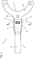
- FIGS. 1 to 3 a first connection section 2 of a support device 1 is shown, wherein due to the mirror-image configuration of the second connection section, which is opposite to the first connection section 2, a complete representation of the support device 1 was dispensed with.
- the support device 1 has, in the region of the first connection section 2, a connection element 4, which is formed from a single-layered flat material. With a connecting portion 5 of the connecting element 4, the connecting element 4 is arranged within a tubular receiving portion 6 of the carrier 3.
- the receiving portion 6 is formed by flattening an end portion of the formed as a tubular body 8 carrier 3 and lies with its the connection element 4 facing circumferential end face 10 on a shoulder 9 of the connecting element 4, wherein the paragraph 9 the connecting portion 5 of the connecting element 4 of a motor vehicle section 12 of the connection element 4 delimits.
- the motor vehicle section 12 serves to connect the support device 1 to a motor vehicle component (not shown here) and is adapted to its shape.
- the support device 1, the motor vehicle section 12 is formed sickle-shaped and serves to connect the support device 1 with a strut tower of a strut, not shown here.
- connection between the connecting element 4 and the connecting portion 5 of the Carrier 3 is formed by a clinch connection 7, wherein the connecting portion 5 is disposed in the receiving portion 6 formed by flat pressing of the tube body 8 so that opposite surfaces of the connecting portion 5 abut against the opposite portions 11a, 11b of the flattened portion of the tube body 8.
- the clinch connection 7 has a rectangular shape in plan view, which extends substantially perpendicular to a longitudinal axis of the connecting portion 5.
- connection element 4 on the connecting portion 5 prior to the manufacture of the clinch connection 7 takes place by simply inserting the connecting portion 5 in the receiving portion 6 into the in FIGS. 4 to 6 shown position. This is followed by the production of the clinch connection 7 by means of a suitable, not shown here tool, wherein the three areas are pressed together by a punch of the tool under plastic deformation in a die of the tool. The connection element 4 is then fixed fixed to the carrier 3.
Landscapes
- Engineering & Computer Science (AREA)
- Chemical & Material Sciences (AREA)
- Combustion & Propulsion (AREA)
- Transportation (AREA)
- Mechanical Engineering (AREA)
- Motor Or Generator Frames (AREA)
- Connection Of Plates (AREA)
Description
- Die Erfindung betrifft eine Stützvorrichtung zur Übertragung von Lasten an einem Kraftfahrzeug, mit
- einem ersten Anschlussabschnitt zur Verbindung mit einem ersten Kraftfahrzeugbauteil,
- einem zweiten Anschlussabschnitt zur Verbindung mit einem zweiten Kraftfahrzeugbauteil und
- einem den ersten und zweiten Anschlussabschnitt verbindenden Träger.
- Stützvorrichtungen der eingangs genannten Art sind in vielfältigen Ausgestaltungen aus dem Stand der Technik, beispielsweise aus den Druckschriften
US 2015/0183470 A1 ,US 2014/0306417 A1 undJP H10 35235 - Der bestimmungsgemäße Einsatz derartiger Stützvorrichtungen macht es erforderlich, diese einerseits zur ortsfesten Anbindung an den gegeneinander abzustützenden Kraftfahrzeugbauteilen auszubilden und andererseits so stabil auszugestalten, dass gewährleistet ist, dass die im Betrieb auftretenden Kräfte und Momente zuverlässig übertragen werden. Aus dem Stand der Technik ist es bekannt, die an den Kraftfahrzeugbauteilen anzuordnende Anschlussabschnitte als separate Bauteile entsprechend der Geometrie der Kraftfahrzeugbauteile auszugestalten und diese dann zur Bildung der Stützvorrichtung mit einem stabilen Träger zu verbinden, welcher zur Übertragung der auftretenden Lasten ausgebildet ist. Die Verbindung der Anschlussabschnitte mit dem Träger erfolgt dann üblicherweise durch thermische Fügeverfahren. Eine derartige Herstellung weist jedoch den Nachteil auf, dass sie zeit- und kostenaufwändig ist. Zudem besteht die Gefahr eines thermischen Verzugs sowie von Gefügeänderungen aufgrund der bspw. beim Schweißen stattfindenden Wärmeeinbringung in die Bauteile der Stützvorrichtung.
- Der Erfindung liegt die Aufgabe zugrunde eine Stützvorrichtung bereitzustellen, die sich kostengünstig herstellen lässt und eine zuverlässige Übertragung der auftretenden Lasten gewährleistet.
- Die Erfindung löst die Aufgabe durch eine Stützvorrichtung mit den Merkmalen des Anspruchs 1. Vorteilhafte Weiterbildungen der Erfindung sind in den abhängigen Ansprüchen angegeben.
- Kennzeichnend für die erfindungsgemäße Stützvorrichtung ist, dass der erste Anschlussabschnitt und/oder zweite Anschlussabschnitt der Stützvorrichtung ein separates Anschlusselement mit einem einlagigen Verbindungsabschnitt aufweist. Der Verbindungsabschnitt ist dabei zur Bildung der Stützvorrichtung in einem rohrförmigen Aufnahmeabschnitt des Trägers angeordnet und durch eine Clinchverbindung ortsfest mit dem Aufnahmeabschnitt verbunden. Unter einer Clinchverbindung wird dabei im Rahmen der vorliegenden Erfindung eine Verbindung verstanden, die bevorzugt ohne Zusatz- oder Hilfsfügeteile eine unlösbare Verbindung durch lokale Kaltverformung herstellt. Durch die beim Clinchen stattfindende Umformung wird zwischen dem Aufnahmeabschnitt des Trägers und dem Verbindungsabschnitt des Anschlusselements eine zuverlässige formschlüssige Verbindung erzeugt, die eine stabile, sämtliche im Betrieb auftretenden Kräfte und Momente übertragende Stützvorrichtung gewährleistet. Die Ausgestaltung und Formgebung der Clinchverbindung kann dabei grundsätzlich, auch unter Berücksichtigung der zu übertragenden Lasten, in vielfältiger Weise erfolgen.
- Nach der Herstellung der Clinchverbindung zwischen dem rohrförmigen Aufnahmeabschnitt des Trägers und dem einlagigen Verbindungsabschnitts des Anschlusselements ist der rohrförmige Aufnahmeabschnitt derart verformt, dass die Stützvorrichtung im Bereich der Clinchverbindung im Querschnitt dreilagig ausgebildet ist, wobei der einlagige Verbindungsabschnitt mit seinen gegenüberliegenden Flächen an den einander gegenüberliegenden Flächen des rohrförmigen Aufnahmeabschnitts anliegt. Die an den Verbindungsabschnitt angepasste Ausgestaltung des Aufnahmeabschnitts kann dabei bereits vor einer Anordnung des Verbindungsabschnitts in den Aufnahmeabschnitt erfolgen, bspw. durch entsprechendes Flachdrücken eines Rohrabschnitts, so dass dieser einen an den Verbindungsabschnitt angepassten Querschnitt aufweist.
- Beim Herstellen der Clinchverbindung, d. h. beim Clinchen, das auch unter dem Begriff Durchsetzfügen bekannt ist, werden einander gegenüberliegende Bereiche des rohrförmigen Aufnahmeabschnitts sowie ein Bereich des darin angeordneten Verbindungsabschnitts des Anschlusselements gemeinsam in einem einen Stempel und eine Matrize aufweisenden Werkzeug durch den Stempel unter plastischer Deformation in die Matrize gedrückt, so dass eine zuverlässige kraft- und vor allem formschlüssige Verbindung erzeugt wird, durch die das Anschlusselement zuverlässig an den Träger festgelegt ist.
- Die Clinchverbindung zeichnet sich dabei insbesondere dadurch aus, dass vollständig auf ergänzende Befestigungsmittel, wie bspw. Klebemittel, verzichtet werden kann. Im Gegensatz zu thermischen Fügeverfahren ist zudem ausgeschlossen, dass es aufgrund der dabei stattfindenden Wärmeeinbringung zu schädigenden Gefügeänderungen an dem Anschlusselement und/oder Träger kommt oder ein thermischer Verzug auftritt, der eine Anbringung der Stützvorrichtung am Kraftfahrzeug erschwert oder behindert.
- Die erfindungsgemäße Stützvorrichtung lässt sich somit besonders einfach und kostengünstig herstellen. Die Verwendung eines separaten Anschlusselements, welches mit dem Träger über den rohrförmigen Aufnahmeabschnitt verbindbar ist, ermöglicht es, den Träger weitestgehend unabhängig von dem Anschlusselement entsprechend der aufzutretenden Lasten auszuwählen. Das Anschlusselement kann zudem in einfacher Weise entsprechend der Geometrie des anzuschließenden Kraftfahrzeugbauteils ausgelegt werden.
- Gemäß der Erfindung weist die Stützvorrichtung mindestens ein Anschlusselement auf, das separat von dem Träger ausgebildet ist und mit einem Verbindungsabschnitt mit einem rohrförmigen Aufnahmeabschnitt des Trägers ortsfest verbunden ist. Grundsätzlich kann auch der weitere, dem ersten Anschlussabschnitt gegenüberliegende zweite Anschlussabschnitt in derartiger Weise gebildet sein, d. h. ein Anschlusselement aufweisen, welches mit einem rohrförmigen Aufnahmeabschnitt des Trägers durch eine Clinchverbindung verbunden ist. Erfindungsgemäß ist jedoch vorgesehen, dass eines von dem ersten Anschlussabschnitt und dem zweiten Anschlussabschnitt einstückig mit dem Träger ausgebildet ist. Demgemäß kann der Anschlussabschnitt beispielsweise durch eine entsprechende Formgebung des Endabschnitts des Trägers gebildet werden, so dass dieser dann an einem entsprechenden Kraftfahrzeugbauteil angeordnet werden kann. Im Falle der vorgesehenen Verwendung eines Rohrkörpers kann der einstückig mit dem Träger ausgebildete Anschlussabschnitt beispielsweise durch ein einfaches Flachpressen des Rohrkörpers gebildet werden, wobei der Anschlussabschnitt dann an geeigneter Stelle mit dem Kraftfahrzeugbauteil verbunden, beispielsweise verschraubt werden kann. Dies ermöglicht in ergänzender Weise eine kostengünstige Herstellung der Stützvorrichtung, da zur Herstellung des zweiten Anschlussabschnitts auf ein separates Anschlusselement sowie dessen bevorzugte Verbindung durch Clinchen verzichtet werden kann.
Die Ausgestaltung des Trägers kann grundsätzlich in beliebiger Weise erfolgen, wobei dieser zur Anordnung des Verbindungsabschnitts des Anschlusselements lediglich einen entsprechend ausgebildeten rohrförmigen Aufnahmeabschnitt aufweisen muss. Nach einer besonders vorteilhaften Ausgestaltung der Erfindung ist jedoch vorgesehen, dass der Träger einen sich von dem ersten Anschlussabschnitt zum zweiten Anschlussabschnitt erstreckenden Rohrkörper aufweist, besonders bevorzugt aus einem solchen Rohrkörper gebildet ist. Die Verwendung eines Rohrkörpers zeichnet sich dabei insbesondere dadurch aus, dass dieser zum einen in besonders vorteilhafter Weise dazu geeignet ist, sämtliche im Betrieb auftretenden Zug-, Druck- und Querkräfte zuverlässig zu übertragen. Darüber hinaus zeichnet sich der Rohrkörper durch seine Eignung zur Schwingungsaufnahme aus. Ein weiterer Vorteil in der Verwendung eines Rohrkörpers besteht darin, dass dessen Endabschnitte in einfacher Weise zur Bildung der an den Verbindungsabschnitt des Anschlusselements angepasster rohrförmiger Aufnahmeabschnitt genutzt werden kann, wodurch sich die Stützvorrichtungen besonders einfach und kostengünstig herstellen lassen. - Auch der Querschnitt des Rohrkörpers kann in beliebiger Weise entsprechend der auftretenden Lasten frei gewählt werden. So kann der Rohrkörper bspw. einen polygonalen Querschnitt besitzen. Ferner kann sich der Querschnitt auch in Längsachsenrichtung des Trägers in Form, Umfang, Durchmesser und/oder Wanddicke verändern. Nach einer besonders vorteilhaften Weiterbildung der Erfindung ist vorgesehen, dass der Rohrkörper einen kreisförmigen Querschnitt aufweist. Die Verwendung eines rohrförmigen Körper smit einem kreisförmigen Querschnitt zeichnet sich dabei dadurch aus, dass er in besonders zuverlässiger Weise die auftretenden Lasten überträgt, sowie zur Aufnahme sämtlicher im Betrieb auftretenden Schwingungen geeignet ist. Darüber hinaus lässt sich aufgrund des vielfältigen Angebots standardisierter Rohrkörper die Stützvorrichtung besonders einfach und kostengünstig herstellen, wobei auch die Ausbildung des Aufnahmeabschnitts in einfacher Weise durch Flachdrücken der Endabschnitte des Rohrkörpers erfolgen kann.
- Die erfindungsgemäße Stützvorrichtung weist grundsätzlich wenigstens zwei Anschlussabschnitte auf, welche an einem ersten und einem zweiten Kraftfahrzeugbauteil anordbar sind, sodass über die Stützvorrichtung diese Kraftfahrzeugbauteile gegeneinander abgestützt werden. Nach einer besonders vorteilhaften Weiterbildung der Erfindung ist vorgesehen, dass in einem Bereich zwischen dem ersten Anschlussabschnitt und dem zweiten Anschlussabschnitt ein weiteres Anschlusselement an dem Träger angeordnet, bevorzugt durch eine Clinchverbindung des einlagigen Verbindungsabschnitts des weiteren Anschlusselements mit einem rohrförmigen Abschnitt des Trägers verbunden ist.
- Gemäß dieser Ausgestaltung der Erfindung weist die Stützvorrichtung einen weiteren, mindestens dritten Anschlussabschnitt auf, welcher an einem dritten Kraftfahrzeugbauteil befestigbar ist, sodass diese drei Fahrzeugbauteile in montiertem Zustand der Stützvorrichtung im Fahrzeug über die Stützvorrichtung gegeneinander abgestützt sind. Die Anordnung dieses weiteren Anschlusselements erfolgt dabei bevorzugt ebenfalls durch eine Clinchverbindung des einlagigen Verbindungsabschnitts des Anschlusselements mit einem rohrförmigen Abschnitt des Trägers. Insbesondere die vorteilhafter Weise vorgesehene Verwendung eines Rohrkörpers zeichnet sich dabei dadurch aus, dass dieser in einfacher Weise im Bereich zwischen dem ersten und zweiten Anschlussabschnitt mit weiteren Anschlusselementen versehen werden kann, nachdem hierzu der Rohrkörper lediglich mit einer Öffnung versehen werden muss, in die der einlagige Verbindungsabschnitt des Anschlusselements eingesteckt und anschließend in diesem Bereich mit dem Rohrkörper durch Clinchen verbunden wird. Gemäß dieser Ausgestaltung der Erfindung lassen sich somit besonders kompakte und komplexe Stützvorrichtungen besonders einfach und kostengünstig herstellen.
- Nach einer weiteren Ausgestaltung der Erfindung ist vorgesehen, dass der Verbindungsabschnitt des Anschlusselements gegenüber dessen Kraftfahrzeugabschnitt abgesetzt ist. Bei dem Verbindungsabschnitt des Anschlusselements handelt es sich um den Bereich des Anschlusselements, welcher im Bereich des rohrförmigen Aufnahmeabschnittes des Trägers angeordnet ist. Der Kraftfahrzeugabschnitt hingegen dient zur Verbindung mit dem zu verbindenden Kraftfahrzeugbauteil und weist hierzu beispielsweise entsprechende Bohrung zur Aufnahme von Schraubverbindungen auf. Gemäß dieser Weiterbildung der Erfindung ist vorgesehen, dass der Verbindungsabschnitt gegenüber dem Kraftfahrzeugabschnitt abgesetzt ist, d. h. eine abweichende Dicke und oder Breite aufweist. Die Ausgestaltung des Übergangsbereichs zwischen dem Verbindungsabschnitt und dem Anschlusselement kann dabei grundsätzlich in beliebiger Weise, beispielsweise durch kontinuierlich ansteigende Flächen oder eine bogenförmige Ausgestaltung erreicht werden, wobei die abgesetzte Ausgestaltung die Möglichkeit bietet, den Träger gegenüber dem Anschlusselement formschlüssig - in Einschubrichtung des Verbindungsabschnitts in den Aufnahmeabschnitt betrachtet - abzustützen.
- Nach einer besonders vorteilhaften Ausgestaltung der Erfindung ist dabei vorgesehen, dass der Aufnahmeabschnitt stirnseitig an einem Absatz zwischen Kraftfahrzeugabschnitt und Verbindungsabschnitt des Anschlusselements anliegt. Die Ausgestaltung des Übergangsbereichs zwischen dem Aufnahmeabschnitt und dem Kraftfahrzeugabschnitt durch einen Absatz lässt sich besonders einfach und kostengünstig herstellen. Zudem kann durch eine entsprechende Dimensionierung des rohrförmigen Aufnahmeabschnitts in einfacher Weise eine stirnseitige Abstützung des rohrförmigen Aufnahmeabschnitts an dem Anschlusselement erreicht werden, wodurch eine zuverlässige Positionierung und Übertragung sämtlicher Kräfte, insbesondere in Einschubrichtung des Verbindungsabschnitts in den Aufnahmeabschnitt, gewährleistet ist.
- Die Ausgestaltung des Kraftfahrzeugabschnittes kann in beliebiger Weise entsprechend der Form des anzuschließenden Kraftfahrzeugbauteils gewählt werden. Nach einer besonders vorteilhaften Ausgestaltung der Erfindung weist der Kraftfahrzeugabschnitt einen sichelförmigen Verlauf auf. Ein sichelförmiger Verlauf des Kraftfahrzeugabschnittes ermöglicht die besonders einfache Verwendung der Stützvorrichtung als Domstrebe. Der Durchmesser des sichelförmigen Verlaufs ist dabei an die Dome der zu verbindenden Federbeine angepasst.
- Das Anschlusselement kann grundsätzlich mehrteilig ausgebildet sein, beispielsweise einen einlagigen Verbindungsabschnitt aufweisen, welcher mit einem separaten Kraftfahrzeugabschnitt verbunden ist. Nach einer besonders vorteilhaften Ausgestaltung der Erfindung ist jedoch vorgesehen, dass das Anschlusselement einstückig ausgebildet ist und somit eine durchgehend einlagige Form aufweist. Diese Ausgestaltung der Erfindung ermöglicht es, das Anschlusselement in besonders einfacher Weise herzustellen, beispielsweise aus einem geeigneten Blechmaterial herauszustanzen oder zu schneiden, so dass sich die Stützvorrichtung besonders einfach und kostengünstig herstellen lässt.
- Die Ausgestaltung der Clinchverbindung ist ebenfalls grundsätzlich frei wählbar. Dies betrifft insbesondere die Form, die entsprechend der zu übertragenden Last ausgewählt werden kann. Nach einer besonders vorteilhaften Ausgestaltung der Erfindung ist jedoch vorgesehen, dass die Clinchverbindung eine rechteckige Form aufweist und sich im Wesentlichen senkrecht zur Längsachse des Aufnahmeabschnitts erstreckt. Gemäß dieser Ausgestaltung der Erfindung ist vorgesehen, dass die Clinchverbindung in einer Draufsicht einen rechteckigen Verlauf aufweist, wodurch gewährleistet ist, dass eine besonders stabile Verbindung zwischen dem Anschlusselement und dem Träger besteht, so dass sämtliche im Betrieb auftretenden Lasten zuverlässig übertragen werden.
- Nach einer besonders vorteilhaften Ausgestaltung der Erfindung können auch weitere Clinchverbindungen nebeneinander angeordnet sein, wobei besonders bevorzugt Aufnahmeabschnitt und Verbindungsabschnitt durch zwei versetzt zueinander angeordneten Clinchverbindungen miteinander verbunden sind. Gemäß dieser Ausgestaltung der Erfindung können beispielsweise zwei gleichartige, eine rechteckige Form aufweisende Clinchverbindungen parallel zueinander angeordnet sein. Alternativ können die Clinchverbindungen auch abgewinkelt zueinander verlaufen. Bei einer zueinander abgewinkelten Anordnung zweier oder mehrer Clinchverbindungen mit rechteckiger Form verlaufen diese mit einem gleichen oder unterschiedlichen Winkel zu einer Längsachse des Verbindungsabschnitts auf, wobei der Winkel mit der Längsachse zwischen 0° und 90° liegt.
- Ein Ausführungsbeispiel der Erfindung wird nachstehend mit Bezug auf die Zeichnungen erläutert. In den Zeichnungen zeigen:
- Fig. 1
- eine Draufsicht auf eine Stützvorrichtung;
- Fig. 2
- eine Seitenansicht auf die Stützvorrichtung von
Fig. 1 ; - Fig. 3
- eine Ansicht eines Schnitts entlang der Schnittlinie A-A von
Fig. 1 ; - Fig. 4
- eine Draufsicht auf die Stützvorrichtung von
Fig. 1 im nicht geclinchten Zustand; - Fig. 5
- eine Seitenansicht auf die Stützvorrichtung von
Fig. 1 im nicht geclinchten Zustand und - Fig. 6
- eine Ansicht eines Schnitts entlang der Schnittlinie A-A von
Fig. 4 . - In den
Figuren 1 bis 3 ist ein erster Anschlussabschnitt 2 einer Stützvorrichtung 1 dargestellt, wobei aufgrund der spiegelbildlichen Ausgestaltung des zweiten Anschlussabschnitts, welcher dem ersten Anschlussabschnitt 2 gegenüberliegt, auf eine vollständige Darstellung der Stützvorrichtung 1 verzichtet wurde. - Die Stützvorrichtung 1 weist im Bereich des ersten Anschlussabschnitts 2 ein Anschlusselement 4 auf, welches aus einem einlagigen Flachmaterial gebildet ist. Mit einem Verbindungsabschnitt 5 des Anschlusselements 4 ist das Anschlusselement 4 innerhalb eines rohrförmigen Aufnahmeabschnitts 6 des Trägers 3 angeordnet. Der Aufnahmeabschnitt 6 ist dabei durch Flachdrücken eines Endbereichs des als Rohrkörper 8 ausgebildeten Trägers 3 gebildet und liegt mit seiner dem Anschlusselement 4 zugewandten umlaufenden Stirnseite 10 an einem Absatz 9 des Anschlusselements 4 an, wobei der Absatz 9 den Verbindungsabschnitt 5 des Anschlusselements 4 von einem Kraftfahrzeugabschnitt 12 des Anschlusselements 4 abgrenzt. Der Kraftfahrzeugabschnitt 12 dient dabei zur Anbindung der Stützvorrichtung 1 an ein hier nicht dargestelltes Kraftfahrzeugbauteil und ist an dessen Form angepasst. In dem dargestellten Ausführungsbeispiel der Stützvorrichtung 1 ist der Kraftfahrzeugabschnitt 12 sichelförmig ausgebildet und dient zur Verbindung der Stützvorrichtung 1 mit einem hier nicht dargestellten Federbeindom eines Federbeins.
- Die Verbindung zwischen dem Anschlusselement 4 und dem Verbindungsabschnitt 5 des Trägers 3 erfolgt durch eine Clinchverbindung 7 wobei der Verbindungsabschnitt 5 in dem durch Flachpressen des Rohrkörpers 8 gebildeten Aufnahmeabschnitt 6 angeordnet ist, so dass gegenüberliegende Flächen des Verbindungsabschnitts 5 an den gegenüberliegenden Abschnitten 11a, 11b des flachgedrückten Bereichs des Rohrkörpers 8 anliegen. In diesem Bereich sind der Verbindungsabschnitt 5 und der Aufnahmeabschnitt 6 durch die Clinchverbindung 7 kraft- und formschlüssig aneinander festgelegt, wobei durch das dreiwandige Clinchen die entsprechenden Bereiche von Verbindungsabschnitt 5 und Aufnahmeabschnitt 6 gemeinsam verformt sind (vgl.
Fig. 3 ). Die Clinchverbindung 7 weist eine in der Draufsicht rechteckige Form auf, die sich im Wesentlichen senkrecht zu einer Längsachse des Verbindungsabschnitts 5 erstreckt. - Die Anordnung des Anschlusselements 4 an dem Verbindungsabschnitt 5 vor dem Herstellen der Clinchverbindung 7 erfolgt durch einfaches Einsteckendes Verbindungsabschnitts 5 in den Aufnahmeabschnitt 6 bis in die in
Figuren 4 bis 6 dargestellte Position. Hieran anschließend erfolgt die Herstellung der Clinchverbindung 7 mittels eines geeigneten, hier nicht dargestellten Werkzeugs, wobei die drei Bereiche gemeinsam durch einen Stempel des Werkzeugs unter plastischer Deformation in eine Matrize des Werkzeugs gedrückt werden. Das Anschlusselement 4 ist hiernach ortsfest an dem Träger 3 festgelegt. -
- 1
- Stützvorrichtung
- 2
- erster Anschlussabschnitt (Stützvorrichtung)
- 3
- Träger
- 4
- Anschlusselement
- 5
- Verbindungsabschnitt
- 6
- Aufnahmeabschnitt (Träger)
- 7
- Clinchverbindung
- 8
- Rohrkörper
- 9
- Absatz
- 10
- Stirnseite
- 11a, 11b
- Abschnitte
- 12
- Kraftfahrzeugabschnitt
Claims (9)
- Stützvorrichtung zur Übertragung von Lasten an einem Kraftfahrzeug, mit- einem ersten Anschlussabschnitt zur Verbindung mit einem ersten Kraftfahrzeugbauteil,- einem zweiten Anschlussabschnitt zur Verbindung mit einem zweiten Kraftfahrzeugbauteil und- einem den ersten und zweiten Anschlussabschnitt verbindenden Träger,dadurch gekennzeichnet, dass der erste Anschlussabschnitt (2) und/oder zweite Anschlussabschnitt ein Anschlusselement (4) mit einem einlagigen Verbindungsabschnitt (5) aufweist, der in einem rohrförmigen Aufnahmeabschnitt (6) des Trägers (3) angeordnet und durch eine Clinchverbindung (7) ortsfest mit dem Aufnahmeabschnitt (6) verbunden ist und die Stützvorrichtung (1) im Bereich der Clinchverbindung (7) dreilagig ausgebildet ist und eines von dem ersten Anschlussabschnitt (2) und dem zweiten Anschlussabschnitt einstückig mit dem Träger (3) ausgebildet ist.
- Stützvorrichtung nach Anspruch 1, dadurch gekennzeichnet, dass der Träger (3) einen sich von dem ersten Anschlussabschnitt (2) zum zweiten Anschlussabschnitt erstreckenden Rohrkörper (8) aufweist.
- Stützvorrichtung nach Anspruch 1 oder 2, dadurch gekennzeichnet, dass der Rohrkörper (8) einen kreisförmigen Querschnitt aufweist.
- Stützvorrichtung nach einem oder mehreren der vorhergehenden Ansprüche, dadurch gekennzeichnet, dass in einem Bereich zwischen dem ersten Anschlussabschnitt (2) und dem zweiten Anschlussabschnitt ein weiteres Anschlusselement (4) an dem Träger (3) angeordnet und durch eine Clinchverbindung (7) des einlagigen Verbindungsabschnitts (5) des weiteren Anschlusselements (4) mit einem rohrförmigen Abschnitt des Trägers (3) verbunden ist.
- Stützvorrichtung nach einem der vorliegenden Ansprüche, dadurch gekennzeichnet, dass der Verbindungsabschnitt (5) gegenüber einem Kraftfahrzeugabschnitt (12) des Anschlusselements (4) abgesetzt ist.
- Stützvorrichtung nach einem oder mehreren der vorhergehenden Ansprüche, dadurch gekennzeichnet, dass der Aufnahmeabschnitt (6) stirnseitig an einem Absatz (9) zwischen Kraftfahrzeugabschnitt (12) und Verbindungsabschnitt (5) des Anschlusselements (4) anliegt.
- Stützvorrichtung nach Anspruch 6 oder 7, dadurch gekennzeichnet, dass der Kraftfahrzeugabschnitt (12) einen sichelförmigen Verlauf aufweist.
- Stützvorrichtung nach einem oder mehreren der vorhergehenden Ansprüche, dadurch gekennzeichnet, dass die Clinchverbindung (7) eine rechteckige Form aufweist und sich im Wesentlichen senkrecht zur Längsachse des Aufnahmeabschnitts (6) erstreckt.
- Stützvorrichtung nach einem oder mehreren der vorhergehenden Ansprüche, dadurch gekennzeichnet, dass der Aufnahmeabschnitt (6) und der Verbindungsabschnitt (5) durch zwei versetzt zueinander angeordneten Clinchverbindungen (7) miteinander verbunden sind.
Applications Claiming Priority (1)
| Application Number | Priority Date | Filing Date | Title |
|---|---|---|---|
| DE102015113233.8A DE102015113233A1 (de) | 2015-08-11 | 2015-08-11 | Stützvorrichtung zur Übertragung von Lasten an einem Kraftfahrzeug |
Publications (3)
| Publication Number | Publication Date |
|---|---|
| EP3130527A1 EP3130527A1 (de) | 2017-02-15 |
| EP3130527B1 true EP3130527B1 (de) | 2019-07-31 |
| EP3130527B8 EP3130527B8 (de) | 2019-09-25 |
Family
ID=56024188
Family Applications (1)
| Application Number | Title | Priority Date | Filing Date |
|---|---|---|---|
| EP16170396.2A Active EP3130527B8 (de) | 2015-08-11 | 2016-05-19 | Stützvorrichtung zur übertragung von lasten an einem kraftfahrzeug |
Country Status (2)
| Country | Link |
|---|---|
| EP (1) | EP3130527B8 (de) |
| DE (1) | DE102015113233A1 (de) |
Families Citing this family (1)
| Publication number | Priority date | Publication date | Assignee | Title |
|---|---|---|---|---|
| EP3678921A4 (de) * | 2017-09-06 | 2021-05-05 | Phancharoen, Chanapong | Strebengepresster stab |
Citations (1)
| Publication number | Priority date | Publication date | Assignee | Title |
|---|---|---|---|---|
| JPH1035235A (ja) * | 1996-07-26 | 1998-02-10 | Showa Alum Corp | サスペンションアーム材 |
Family Cites Families (5)
| Publication number | Priority date | Publication date | Assignee | Title |
|---|---|---|---|---|
| JP2004106704A (ja) * | 2002-09-18 | 2004-04-08 | Fuji Heavy Ind Ltd | 自動車の車体前部構造 |
| JP4052596B2 (ja) * | 2004-08-03 | 2008-02-27 | 本田技研工業株式会社 | タワー連結バー構造 |
| JP4121529B2 (ja) * | 2006-04-20 | 2008-07-23 | 本田技研工業株式会社 | 車体前部構造 |
| JP6000932B2 (ja) * | 2013-02-20 | 2016-10-05 | 株式会社神戸製鋼所 | 構造体の連結部材の製造方法 |
| US20140306417A1 (en) * | 2013-04-16 | 2014-10-16 | Ronald E. McCormick | Vehicle suspension tower brace assembly |
-
2015
- 2015-08-11 DE DE102015113233.8A patent/DE102015113233A1/de not_active Ceased
-
2016
- 2016-05-19 EP EP16170396.2A patent/EP3130527B8/de active Active
Patent Citations (1)
| Publication number | Priority date | Publication date | Assignee | Title |
|---|---|---|---|---|
| JPH1035235A (ja) * | 1996-07-26 | 1998-02-10 | Showa Alum Corp | サスペンションアーム材 |
Also Published As
| Publication number | Publication date |
|---|---|
| EP3130527B8 (de) | 2019-09-25 |
| DE102015113233A1 (de) | 2017-02-16 |
| EP3130527A1 (de) | 2017-02-15 |
Similar Documents
| Publication | Publication Date | Title |
|---|---|---|
| EP2648968B1 (de) | Verbindungsanordnung | |
| EP2467231B1 (de) | Verfahren zur herstellung eines einen abschnitt einer lenkspindel bildenden lenkspindelteils | |
| DE102014103796A1 (de) | System zur elastisch gemittelten Ausrichtung | |
| EP2637912B1 (de) | Lenkerelement mit überlastsicherung | |
| EP3157769B1 (de) | Verfahren zur herstellung eines fahrwerkbauteils | |
| EP2511129A1 (de) | Kraftfahrzeugsitztraverse | |
| DE10250843B4 (de) | Wischlager für eine Wischerwelle einer Scheibenwischanlage sowie Verfahren zum Herstellen einer Verbindung zwischen einem Wischlager und einem Halterohr einer Scheibenwischanlage | |
| DE102013015518A1 (de) | Kraftfahrzeug-Strukturteil mit einer Kopplingsvorrichtung für eine Abschleppöse, Herstellverfahren hierfür, sowie eine Abschleppanordnung und Kraftfahrzeug | |
| EP2558733B1 (de) | Spreizeinrichtung, verbindung sowie system | |
| EP2483135A1 (de) | Verstärkungsanordnung für eine türsäule eines personenkraftwagens und verfahren zum herstellen einer solchen verstärkungsanordnung | |
| EP2000335B1 (de) | Achskomponente und Verfahren zur Herstellung einer Achskomponente | |
| DE102009014206B4 (de) | Cockpitquerträger | |
| EP3054182B1 (de) | Verfahren zur herstellung einer fügeverbindung zwischen einem gelenkgehäuse und einem anbindungsbauteil, sowie verfahrensgemäss hergestelltes fahrwerkbauteil | |
| EP3130527A1 (de) | Stützvorrichtung zur übertragung von lasten an einem kraftfahrzeug | |
| DE102014101757B4 (de) | Hohlprofilbauteil mit Flansch | |
| EP3642060B1 (de) | Verfahren zur herstellung eines fahrzeugbauteils und fahrzeugbauteil hergestellt nach diesem verfahren | |
| DE102006022382A1 (de) | Vorrichtung und Verfahren zur Befestigung eines Wischermotors an ein Wischergestänge | |
| DE102009046141A1 (de) | Lenkgetriebe für ein Lenksystem und Verfahren zur Montage desselben | |
| EP1771310B1 (de) | Zylinderbaugruppe mit einem achsanschluss | |
| EP3524836A1 (de) | Axialkugelzapfen | |
| DE20308895U1 (de) | Querträger zum Halten der Instrumententafel in einem Kraftfahrzeug | |
| DE102012019379A1 (de) | Energieabsorptionselement für einen Kraftwagen | |
| EP2193980A1 (de) | Rohrbügel für eine Klappe eines Kraftfahrzeugs | |
| EP2522863B1 (de) | Verbindungsstift | |
| DE102013020801A1 (de) | Verfahren zum Fügen wenigstens zweier Baueile mittels einer Fließformniethülse |
Legal Events
| Date | Code | Title | Description |
|---|---|---|---|
| PUAI | Public reference made under article 153(3) epc to a published international application that has entered the european phase |
Free format text: ORIGINAL CODE: 0009012 |
|
| STAA | Information on the status of an ep patent application or granted ep patent |
Free format text: STATUS: THE APPLICATION HAS BEEN PUBLISHED |
|
| AK | Designated contracting states |
Kind code of ref document: A1 Designated state(s): AL AT BE BG CH CY CZ DE DK EE ES FI FR GB GR HR HU IE IS IT LI LT LU LV MC MK MT NL NO PL PT RO RS SE SI SK SM TR |
|
| AX | Request for extension of the european patent |
Extension state: BA ME |
|
| STAA | Information on the status of an ep patent application or granted ep patent |
Free format text: STATUS: REQUEST FOR EXAMINATION WAS MADE |
|
| 17P | Request for examination filed |
Effective date: 20170706 |
|
| RBV | Designated contracting states (corrected) |
Designated state(s): AL AT BE BG CH CY CZ DE DK EE ES FI FR GB GR HR HU IE IS IT LI LT LU LV MC MK MT NL NO PL PT RO RS SE SI SK SM TR |
|
| STAA | Information on the status of an ep patent application or granted ep patent |
Free format text: STATUS: EXAMINATION IS IN PROGRESS |
|
| 17Q | First examination report despatched |
Effective date: 20180205 |
|
| REG | Reference to a national code |
Ref country code: DE Ref legal event code: R079 Ref document number: 502016005765 Country of ref document: DE Free format text: PREVIOUS MAIN CLASS: B62D0025080000 Ipc: B62D0025000000 |
|
| GRAP | Despatch of communication of intention to grant a patent |
Free format text: ORIGINAL CODE: EPIDOSNIGR1 |
|
| STAA | Information on the status of an ep patent application or granted ep patent |
Free format text: STATUS: GRANT OF PATENT IS INTENDED |
|
| RIC1 | Information provided on ipc code assigned before grant |
Ipc: B62D 25/08 20060101ALI20190220BHEP Ipc: B62D 25/00 20060101AFI20190220BHEP |
|
| INTG | Intention to grant announced |
Effective date: 20190314 |
|
| GRAS | Grant fee paid |
Free format text: ORIGINAL CODE: EPIDOSNIGR3 |
|
| GRAA | (expected) grant |
Free format text: ORIGINAL CODE: 0009210 |
|
| STAA | Information on the status of an ep patent application or granted ep patent |
Free format text: STATUS: THE PATENT HAS BEEN GRANTED |
|
| AK | Designated contracting states |
Kind code of ref document: B1 Designated state(s): AL AT BE BG CH CY CZ DE DK EE ES FI FR GB GR HR HU IE IS IT LI LT LU LV MC MK MT NL NO PL PT RO RS SE SI SK SM TR |
|
| REG | Reference to a national code |
Ref country code: CH Ref legal event code: EP Ref country code: GB Ref legal event code: FG4D Free format text: NOT ENGLISH |
|
| REG | Reference to a national code |
Ref country code: AT Ref legal event code: REF Ref document number: 1160588 Country of ref document: AT Kind code of ref document: T Effective date: 20190815 |
|
| REG | Reference to a national code |
Ref country code: IE Ref legal event code: FG4D Free format text: LANGUAGE OF EP DOCUMENT: GERMAN |
|
| REG | Reference to a national code |
Ref country code: DE Ref legal event code: R096 Ref document number: 502016005765 Country of ref document: DE |
|
| REG | Reference to a national code |
Ref country code: CH Ref legal event code: PK Free format text: TITEL Ref country code: CH Ref legal event code: PK Free format text: BERICHTIGUNG B8 |
|
| REG | Reference to a national code |
Ref country code: NL Ref legal event code: MP Effective date: 20190731 |
|
| REG | Reference to a national code |
Ref country code: LT Ref legal event code: MG4D |
|
| PG25 | Lapsed in a contracting state [announced via postgrant information from national office to epo] |
Ref country code: PT Free format text: LAPSE BECAUSE OF FAILURE TO SUBMIT A TRANSLATION OF THE DESCRIPTION OR TO PAY THE FEE WITHIN THE PRESCRIBED TIME-LIMIT Effective date: 20191202 Ref country code: LT Free format text: LAPSE BECAUSE OF FAILURE TO SUBMIT A TRANSLATION OF THE DESCRIPTION OR TO PAY THE FEE WITHIN THE PRESCRIBED TIME-LIMIT Effective date: 20190731 Ref country code: BG Free format text: LAPSE BECAUSE OF FAILURE TO SUBMIT A TRANSLATION OF THE DESCRIPTION OR TO PAY THE FEE WITHIN THE PRESCRIBED TIME-LIMIT Effective date: 20191031 Ref country code: NL Free format text: LAPSE BECAUSE OF FAILURE TO SUBMIT A TRANSLATION OF THE DESCRIPTION OR TO PAY THE FEE WITHIN THE PRESCRIBED TIME-LIMIT Effective date: 20190731 Ref country code: SE Free format text: LAPSE BECAUSE OF FAILURE TO SUBMIT A TRANSLATION OF THE DESCRIPTION OR TO PAY THE FEE WITHIN THE PRESCRIBED TIME-LIMIT Effective date: 20190731 Ref country code: NO Free format text: LAPSE BECAUSE OF FAILURE TO SUBMIT A TRANSLATION OF THE DESCRIPTION OR TO PAY THE FEE WITHIN THE PRESCRIBED TIME-LIMIT Effective date: 20191031 Ref country code: HR Free format text: LAPSE BECAUSE OF FAILURE TO SUBMIT A TRANSLATION OF THE DESCRIPTION OR TO PAY THE FEE WITHIN THE PRESCRIBED TIME-LIMIT Effective date: 20190731 Ref country code: FI Free format text: LAPSE BECAUSE OF FAILURE TO SUBMIT A TRANSLATION OF THE DESCRIPTION OR TO PAY THE FEE WITHIN THE PRESCRIBED TIME-LIMIT Effective date: 20190731 |
|
| PG25 | Lapsed in a contracting state [announced via postgrant information from national office to epo] |
Ref country code: IS Free format text: LAPSE BECAUSE OF FAILURE TO SUBMIT A TRANSLATION OF THE DESCRIPTION OR TO PAY THE FEE WITHIN THE PRESCRIBED TIME-LIMIT Effective date: 20191130 Ref country code: LV Free format text: LAPSE BECAUSE OF FAILURE TO SUBMIT A TRANSLATION OF THE DESCRIPTION OR TO PAY THE FEE WITHIN THE PRESCRIBED TIME-LIMIT Effective date: 20190731 Ref country code: RS Free format text: LAPSE BECAUSE OF FAILURE TO SUBMIT A TRANSLATION OF THE DESCRIPTION OR TO PAY THE FEE WITHIN THE PRESCRIBED TIME-LIMIT Effective date: 20190731 Ref country code: ES Free format text: LAPSE BECAUSE OF FAILURE TO SUBMIT A TRANSLATION OF THE DESCRIPTION OR TO PAY THE FEE WITHIN THE PRESCRIBED TIME-LIMIT Effective date: 20190731 Ref country code: GR Free format text: LAPSE BECAUSE OF FAILURE TO SUBMIT A TRANSLATION OF THE DESCRIPTION OR TO PAY THE FEE WITHIN THE PRESCRIBED TIME-LIMIT Effective date: 20191101 Ref country code: AL Free format text: LAPSE BECAUSE OF FAILURE TO SUBMIT A TRANSLATION OF THE DESCRIPTION OR TO PAY THE FEE WITHIN THE PRESCRIBED TIME-LIMIT Effective date: 20190731 |
|
| PG25 | Lapsed in a contracting state [announced via postgrant information from national office to epo] |
Ref country code: TR Free format text: LAPSE BECAUSE OF FAILURE TO SUBMIT A TRANSLATION OF THE DESCRIPTION OR TO PAY THE FEE WITHIN THE PRESCRIBED TIME-LIMIT Effective date: 20190731 |
|
| PG25 | Lapsed in a contracting state [announced via postgrant information from national office to epo] |
Ref country code: RO Free format text: LAPSE BECAUSE OF FAILURE TO SUBMIT A TRANSLATION OF THE DESCRIPTION OR TO PAY THE FEE WITHIN THE PRESCRIBED TIME-LIMIT Effective date: 20190731 Ref country code: EE Free format text: LAPSE BECAUSE OF FAILURE TO SUBMIT A TRANSLATION OF THE DESCRIPTION OR TO PAY THE FEE WITHIN THE PRESCRIBED TIME-LIMIT Effective date: 20190731 Ref country code: IT Free format text: LAPSE BECAUSE OF FAILURE TO SUBMIT A TRANSLATION OF THE DESCRIPTION OR TO PAY THE FEE WITHIN THE PRESCRIBED TIME-LIMIT Effective date: 20190731 Ref country code: DK Free format text: LAPSE BECAUSE OF FAILURE TO SUBMIT A TRANSLATION OF THE DESCRIPTION OR TO PAY THE FEE WITHIN THE PRESCRIBED TIME-LIMIT Effective date: 20190731 Ref country code: PL Free format text: LAPSE BECAUSE OF FAILURE TO SUBMIT A TRANSLATION OF THE DESCRIPTION OR TO PAY THE FEE WITHIN THE PRESCRIBED TIME-LIMIT Effective date: 20190731 |
|
| PG25 | Lapsed in a contracting state [announced via postgrant information from national office to epo] |
Ref country code: CZ Free format text: LAPSE BECAUSE OF FAILURE TO SUBMIT A TRANSLATION OF THE DESCRIPTION OR TO PAY THE FEE WITHIN THE PRESCRIBED TIME-LIMIT Effective date: 20190731 Ref country code: IS Free format text: LAPSE BECAUSE OF FAILURE TO SUBMIT A TRANSLATION OF THE DESCRIPTION OR TO PAY THE FEE WITHIN THE PRESCRIBED TIME-LIMIT Effective date: 20200224 Ref country code: SK Free format text: LAPSE BECAUSE OF FAILURE TO SUBMIT A TRANSLATION OF THE DESCRIPTION OR TO PAY THE FEE WITHIN THE PRESCRIBED TIME-LIMIT Effective date: 20190731 Ref country code: SM Free format text: LAPSE BECAUSE OF FAILURE TO SUBMIT A TRANSLATION OF THE DESCRIPTION OR TO PAY THE FEE WITHIN THE PRESCRIBED TIME-LIMIT Effective date: 20190731 |
|
| REG | Reference to a national code |
Ref country code: DE Ref legal event code: R097 Ref document number: 502016005765 Country of ref document: DE |
|
| PLBE | No opposition filed within time limit |
Free format text: ORIGINAL CODE: 0009261 |
|
| STAA | Information on the status of an ep patent application or granted ep patent |
Free format text: STATUS: NO OPPOSITION FILED WITHIN TIME LIMIT |
|
| PG2D | Information on lapse in contracting state deleted |
Ref country code: IS |
|
| PG25 | Lapsed in a contracting state [announced via postgrant information from national office to epo] |
Ref country code: IS Free format text: LAPSE BECAUSE OF FAILURE TO SUBMIT A TRANSLATION OF THE DESCRIPTION OR TO PAY THE FEE WITHIN THE PRESCRIBED TIME-LIMIT Effective date: 20191030 |
|
| 26N | No opposition filed |
Effective date: 20200603 |
|
| PG25 | Lapsed in a contracting state [announced via postgrant information from national office to epo] |
Ref country code: SI Free format text: LAPSE BECAUSE OF FAILURE TO SUBMIT A TRANSLATION OF THE DESCRIPTION OR TO PAY THE FEE WITHIN THE PRESCRIBED TIME-LIMIT Effective date: 20190731 |
|
| PG25 | Lapsed in a contracting state [announced via postgrant information from national office to epo] |
Ref country code: MC Free format text: LAPSE BECAUSE OF FAILURE TO SUBMIT A TRANSLATION OF THE DESCRIPTION OR TO PAY THE FEE WITHIN THE PRESCRIBED TIME-LIMIT Effective date: 20190731 Ref country code: LI Free format text: LAPSE BECAUSE OF NON-PAYMENT OF DUE FEES Effective date: 20200531 Ref country code: CH Free format text: LAPSE BECAUSE OF NON-PAYMENT OF DUE FEES Effective date: 20200531 |
|
| REG | Reference to a national code |
Ref country code: BE Ref legal event code: MM Effective date: 20200531 |
|
| GBPC | Gb: european patent ceased through non-payment of renewal fee |
Effective date: 20200519 |
|
| PG25 | Lapsed in a contracting state [announced via postgrant information from national office to epo] |
Ref country code: LU Free format text: LAPSE BECAUSE OF NON-PAYMENT OF DUE FEES Effective date: 20200519 |
|
| PG25 | Lapsed in a contracting state [announced via postgrant information from national office to epo] |
Ref country code: GB Free format text: LAPSE BECAUSE OF NON-PAYMENT OF DUE FEES Effective date: 20200519 Ref country code: IE Free format text: LAPSE BECAUSE OF NON-PAYMENT OF DUE FEES Effective date: 20200519 Ref country code: FR Free format text: LAPSE BECAUSE OF NON-PAYMENT OF DUE FEES Effective date: 20200531 |
|
| PG25 | Lapsed in a contracting state [announced via postgrant information from national office to epo] |
Ref country code: BE Free format text: LAPSE BECAUSE OF NON-PAYMENT OF DUE FEES Effective date: 20200531 |
|
| PG25 | Lapsed in a contracting state [announced via postgrant information from national office to epo] |
Ref country code: MT Free format text: LAPSE BECAUSE OF FAILURE TO SUBMIT A TRANSLATION OF THE DESCRIPTION OR TO PAY THE FEE WITHIN THE PRESCRIBED TIME-LIMIT Effective date: 20190731 Ref country code: CY Free format text: LAPSE BECAUSE OF FAILURE TO SUBMIT A TRANSLATION OF THE DESCRIPTION OR TO PAY THE FEE WITHIN THE PRESCRIBED TIME-LIMIT Effective date: 20190731 |
|
| PG25 | Lapsed in a contracting state [announced via postgrant information from national office to epo] |
Ref country code: MK Free format text: LAPSE BECAUSE OF FAILURE TO SUBMIT A TRANSLATION OF THE DESCRIPTION OR TO PAY THE FEE WITHIN THE PRESCRIBED TIME-LIMIT Effective date: 20190731 |
|
| REG | Reference to a national code |
Ref country code: AT Ref legal event code: MM01 Ref document number: 1160588 Country of ref document: AT Kind code of ref document: T Effective date: 20210519 |
|
| PG25 | Lapsed in a contracting state [announced via postgrant information from national office to epo] |
Ref country code: AT Free format text: LAPSE BECAUSE OF NON-PAYMENT OF DUE FEES Effective date: 20210519 |
|
| PGFP | Annual fee paid to national office [announced via postgrant information from national office to epo] |
Ref country code: DE Payment date: 20250526 Year of fee payment: 10 |