EP3130054B1 - Power supply apparatus - Google Patents
Power supply apparatus Download PDFInfo
- Publication number
- EP3130054B1 EP3130054B1 EP15717202.4A EP15717202A EP3130054B1 EP 3130054 B1 EP3130054 B1 EP 3130054B1 EP 15717202 A EP15717202 A EP 15717202A EP 3130054 B1 EP3130054 B1 EP 3130054B1
- Authority
- EP
- European Patent Office
- Prior art keywords
- electronic device
- controller
- power supply
- power
- supply apparatus
- Prior art date
- Legal status (The legal status is an assumption and is not a legal conclusion. Google has not performed a legal analysis and makes no representation as to the accuracy of the status listed.)
- Active
Links
Images

Classifications
-
- H—ELECTRICITY
- H01—ELECTRIC ELEMENTS
- H01M—PROCESSES OR MEANS, e.g. BATTERIES, FOR THE DIRECT CONVERSION OF CHEMICAL ENERGY INTO ELECTRICAL ENERGY
- H01M8/00—Fuel cells; Manufacture thereof
- H01M8/04—Auxiliary arrangements, e.g. for control of pressure or for circulation of fluids
- H01M8/04082—Arrangements for control of reactant parameters, e.g. pressure or concentration
- H01M8/04201—Reactant storage and supply, e.g. means for feeding, pipes
- H01M8/04208—Cartridges, cryogenic media or cryogenic reservoirs
-
- H—ELECTRICITY
- H01—ELECTRIC ELEMENTS
- H01M—PROCESSES OR MEANS, e.g. BATTERIES, FOR THE DIRECT CONVERSION OF CHEMICAL ENERGY INTO ELECTRICAL ENERGY
- H01M8/00—Fuel cells; Manufacture thereof
- H01M8/10—Fuel cells with solid electrolytes
- H01M8/1009—Fuel cells with solid electrolytes with one of the reactants being liquid, solid or liquid-charged
- H01M8/1011—Direct alcohol fuel cells [DAFC], e.g. direct methanol fuel cells [DMFC]
-
- B—PERFORMING OPERATIONS; TRANSPORTING
- B60—VEHICLES IN GENERAL
- B60L—PROPULSION OF ELECTRICALLY-PROPELLED VEHICLES; SUPPLYING ELECTRIC POWER FOR AUXILIARY EQUIPMENT OF ELECTRICALLY-PROPELLED VEHICLES; ELECTRODYNAMIC BRAKE SYSTEMS FOR VEHICLES IN GENERAL; MAGNETIC SUSPENSION OR LEVITATION FOR VEHICLES; MONITORING OPERATING VARIABLES OF ELECTRICALLY-PROPELLED VEHICLES; ELECTRIC SAFETY DEVICES FOR ELECTRICALLY-PROPELLED VEHICLES
- B60L50/00—Electric propulsion with power supplied within the vehicle
- B60L50/50—Electric propulsion with power supplied within the vehicle using propulsion power supplied by batteries or fuel cells
- B60L50/70—Electric propulsion with power supplied within the vehicle using propulsion power supplied by batteries or fuel cells using power supplied by fuel cells
-
- B—PERFORMING OPERATIONS; TRANSPORTING
- B60—VEHICLES IN GENERAL
- B60L—PROPULSION OF ELECTRICALLY-PROPELLED VEHICLES; SUPPLYING ELECTRIC POWER FOR AUXILIARY EQUIPMENT OF ELECTRICALLY-PROPELLED VEHICLES; ELECTRODYNAMIC BRAKE SYSTEMS FOR VEHICLES IN GENERAL; MAGNETIC SUSPENSION OR LEVITATION FOR VEHICLES; MONITORING OPERATING VARIABLES OF ELECTRICALLY-PROPELLED VEHICLES; ELECTRIC SAFETY DEVICES FOR ELECTRICALLY-PROPELLED VEHICLES
- B60L58/00—Methods or circuit arrangements for monitoring or controlling batteries or fuel cells, specially adapted for electric vehicles
- B60L58/10—Methods or circuit arrangements for monitoring or controlling batteries or fuel cells, specially adapted for electric vehicles for monitoring or controlling batteries
-
- G—PHYSICS
- G01—MEASURING; TESTING
- G01R—MEASURING ELECTRIC VARIABLES; MEASURING MAGNETIC VARIABLES
- G01R19/00—Arrangements for measuring currents or voltages or for indicating presence or sign thereof
- G01R19/165—Indicating that current or voltage is either above or below a predetermined value or within or outside a predetermined range of values
-
- H—ELECTRICITY
- H01—ELECTRIC ELEMENTS
- H01M—PROCESSES OR MEANS, e.g. BATTERIES, FOR THE DIRECT CONVERSION OF CHEMICAL ENERGY INTO ELECTRICAL ENERGY
- H01M10/00—Secondary cells; Manufacture thereof
- H01M10/42—Methods or arrangements for servicing or maintenance of secondary cells or secondary half-cells
- H01M10/44—Methods for charging or discharging
-
- H—ELECTRICITY
- H01—ELECTRIC ELEMENTS
- H01M—PROCESSES OR MEANS, e.g. BATTERIES, FOR THE DIRECT CONVERSION OF CHEMICAL ENERGY INTO ELECTRICAL ENERGY
- H01M10/00—Secondary cells; Manufacture thereof
- H01M10/42—Methods or arrangements for servicing or maintenance of secondary cells or secondary half-cells
- H01M10/48—Accumulators combined with arrangements for measuring, testing or indicating the condition of cells, e.g. the level or density of the electrolyte
- H01M10/488—Cells or batteries combined with indicating means for external visualization of the condition, e.g. by change of colour or of light density
-
- H—ELECTRICITY
- H01—ELECTRIC ELEMENTS
- H01M—PROCESSES OR MEANS, e.g. BATTERIES, FOR THE DIRECT CONVERSION OF CHEMICAL ENERGY INTO ELECTRICAL ENERGY
- H01M16/00—Structural combinations of different types of electrochemical generators
- H01M16/003—Structural combinations of different types of electrochemical generators of fuel cells with other electrochemical devices, e.g. capacitors, electrolysers
- H01M16/006—Structural combinations of different types of electrochemical generators of fuel cells with other electrochemical devices, e.g. capacitors, electrolysers of fuel cells with rechargeable batteries
-
- H—ELECTRICITY
- H01—ELECTRIC ELEMENTS
- H01M—PROCESSES OR MEANS, e.g. BATTERIES, FOR THE DIRECT CONVERSION OF CHEMICAL ENERGY INTO ELECTRICAL ENERGY
- H01M8/00—Fuel cells; Manufacture thereof
- H01M8/04—Auxiliary arrangements, e.g. for control of pressure or for circulation of fluids
-
- H—ELECTRICITY
- H02—GENERATION; CONVERSION OR DISTRIBUTION OF ELECTRIC POWER
- H02J—CIRCUIT ARRANGEMENTS OR SYSTEMS FOR SUPPLYING OR DISTRIBUTING ELECTRIC POWER; SYSTEMS FOR STORING ELECTRIC ENERGY
- H02J1/00—Circuit arrangements for dc mains or dc distribution networks
-
- H—ELECTRICITY
- H02—GENERATION; CONVERSION OR DISTRIBUTION OF ELECTRIC POWER
- H02J—CIRCUIT ARRANGEMENTS OR SYSTEMS FOR SUPPLYING OR DISTRIBUTING ELECTRIC POWER; SYSTEMS FOR STORING ELECTRIC ENERGY
- H02J7/00—Circuit arrangements for charging or depolarising batteries or for supplying loads from batteries
- H02J7/34—Parallel operation in networks using both storage and other dc sources, e.g. providing buffering
- H02J7/342—The other DC source being a battery actively interacting with the first one, i.e. battery to battery charging
-
- H—ELECTRICITY
- H01—ELECTRIC ELEMENTS
- H01M—PROCESSES OR MEANS, e.g. BATTERIES, FOR THE DIRECT CONVERSION OF CHEMICAL ENERGY INTO ELECTRICAL ENERGY
- H01M10/00—Secondary cells; Manufacture thereof
- H01M10/42—Methods or arrangements for servicing or maintenance of secondary cells or secondary half-cells
- H01M10/425—Structural combination with electronic components, e.g. electronic circuits integrated to the outside of the casing
- H01M2010/4278—Systems for data transfer from batteries, e.g. transfer of battery parameters to a controller, data transferred between battery controller and main controller
-
- H—ELECTRICITY
- H01—ELECTRIC ELEMENTS
- H01M—PROCESSES OR MEANS, e.g. BATTERIES, FOR THE DIRECT CONVERSION OF CHEMICAL ENERGY INTO ELECTRICAL ENERGY
- H01M2250/00—Fuel cells for particular applications; Specific features of fuel cell system
- H01M2250/30—Fuel cells in portable systems, e.g. mobile phone, laptop
-
- H—ELECTRICITY
- H02—GENERATION; CONVERSION OR DISTRIBUTION OF ELECTRIC POWER
- H02J—CIRCUIT ARRANGEMENTS OR SYSTEMS FOR SUPPLYING OR DISTRIBUTING ELECTRIC POWER; SYSTEMS FOR STORING ELECTRIC ENERGY
- H02J2300/00—Systems for supplying or distributing electric power characterised by decentralized, dispersed, or local generation
- H02J2300/30—The power source being a fuel cell
-
- Y—GENERAL TAGGING OF NEW TECHNOLOGICAL DEVELOPMENTS; GENERAL TAGGING OF CROSS-SECTIONAL TECHNOLOGIES SPANNING OVER SEVERAL SECTIONS OF THE IPC; TECHNICAL SUBJECTS COVERED BY FORMER USPC CROSS-REFERENCE ART COLLECTIONS [XRACs] AND DIGESTS
- Y02—TECHNOLOGIES OR APPLICATIONS FOR MITIGATION OR ADAPTATION AGAINST CLIMATE CHANGE
- Y02B—CLIMATE CHANGE MITIGATION TECHNOLOGIES RELATED TO BUILDINGS, e.g. HOUSING, HOUSE APPLIANCES OR RELATED END-USER APPLICATIONS
- Y02B90/00—Enabling technologies or technologies with a potential or indirect contribution to GHG emissions mitigation
- Y02B90/10—Applications of fuel cells in buildings
-
- Y—GENERAL TAGGING OF NEW TECHNOLOGICAL DEVELOPMENTS; GENERAL TAGGING OF CROSS-SECTIONAL TECHNOLOGIES SPANNING OVER SEVERAL SECTIONS OF THE IPC; TECHNICAL SUBJECTS COVERED BY FORMER USPC CROSS-REFERENCE ART COLLECTIONS [XRACs] AND DIGESTS
- Y02—TECHNOLOGIES OR APPLICATIONS FOR MITIGATION OR ADAPTATION AGAINST CLIMATE CHANGE
- Y02E—REDUCTION OF GREENHOUSE GAS [GHG] EMISSIONS, RELATED TO ENERGY GENERATION, TRANSMISSION OR DISTRIBUTION
- Y02E60/00—Enabling technologies; Technologies with a potential or indirect contribution to GHG emissions mitigation
- Y02E60/10—Energy storage using batteries
-
- Y—GENERAL TAGGING OF NEW TECHNOLOGICAL DEVELOPMENTS; GENERAL TAGGING OF CROSS-SECTIONAL TECHNOLOGIES SPANNING OVER SEVERAL SECTIONS OF THE IPC; TECHNICAL SUBJECTS COVERED BY FORMER USPC CROSS-REFERENCE ART COLLECTIONS [XRACs] AND DIGESTS
- Y02—TECHNOLOGIES OR APPLICATIONS FOR MITIGATION OR ADAPTATION AGAINST CLIMATE CHANGE
- Y02E—REDUCTION OF GREENHOUSE GAS [GHG] EMISSIONS, RELATED TO ENERGY GENERATION, TRANSMISSION OR DISTRIBUTION
- Y02E60/00—Enabling technologies; Technologies with a potential or indirect contribution to GHG emissions mitigation
- Y02E60/30—Hydrogen technology
- Y02E60/50—Fuel cells
-
- Y—GENERAL TAGGING OF NEW TECHNOLOGICAL DEVELOPMENTS; GENERAL TAGGING OF CROSS-SECTIONAL TECHNOLOGIES SPANNING OVER SEVERAL SECTIONS OF THE IPC; TECHNICAL SUBJECTS COVERED BY FORMER USPC CROSS-REFERENCE ART COLLECTIONS [XRACs] AND DIGESTS
- Y02—TECHNOLOGIES OR APPLICATIONS FOR MITIGATION OR ADAPTATION AGAINST CLIMATE CHANGE
- Y02T—CLIMATE CHANGE MITIGATION TECHNOLOGIES RELATED TO TRANSPORTATION
- Y02T10/00—Road transport of goods or passengers
- Y02T10/60—Other road transportation technologies with climate change mitigation effect
- Y02T10/70—Energy storage systems for electromobility, e.g. batteries
-
- Y—GENERAL TAGGING OF NEW TECHNOLOGICAL DEVELOPMENTS; GENERAL TAGGING OF CROSS-SECTIONAL TECHNOLOGIES SPANNING OVER SEVERAL SECTIONS OF THE IPC; TECHNICAL SUBJECTS COVERED BY FORMER USPC CROSS-REFERENCE ART COLLECTIONS [XRACs] AND DIGESTS
- Y02—TECHNOLOGIES OR APPLICATIONS FOR MITIGATION OR ADAPTATION AGAINST CLIMATE CHANGE
- Y02T—CLIMATE CHANGE MITIGATION TECHNOLOGIES RELATED TO TRANSPORTATION
- Y02T90/00—Enabling technologies or technologies with a potential or indirect contribution to GHG emissions mitigation
- Y02T90/40—Application of hydrogen technology to transportation, e.g. using fuel cells
Landscapes
- Engineering & Computer Science (AREA)
- General Chemical & Material Sciences (AREA)
- Electrochemistry (AREA)
- Sustainable Development (AREA)
- Sustainable Energy (AREA)
- Chemical & Material Sciences (AREA)
- Chemical Kinetics & Catalysis (AREA)
- Life Sciences & Earth Sciences (AREA)
- Power Engineering (AREA)
- Manufacturing & Machinery (AREA)
- Transportation (AREA)
- Mechanical Engineering (AREA)
- Physics & Mathematics (AREA)
- General Physics & Mathematics (AREA)
- Charge And Discharge Circuits For Batteries Or The Like (AREA)
- Fuel Cell (AREA)
Description
- This invention relates to a power supply apparatus for supplying power generated by a fuel cell to an electronic device, possibly for charging a battery of said electronic device. We also disclose a controller for controlling the flow of power between the power supply apparatus and the electronic device.
- Fuel cells may be used to provide electrical power for electronic devices, such as mobile telephones, portable music players, tablet computers or laptop computers. Typically these electronic devices receive their power from the mains electricity supply. However, when mains electrical power is not available, for example, a fuel cell based power supply apparatus may be used. Such a fuel cell power supply apparatus may comprise a fuel cell that receives a fuel from a fuel storage vessel and any other reactants and generates electrical power which it can then supply to an electronic device coupled to it. The fuel cell power supply apparatus may be portable and include a replaceable fuel storage vessel and is therefore particularly convenient for providing power to use or charge an electronic device.
- Conventional electrochemical fuel cells convert fuel and oxidant, generally both in the form of gaseous streams, into electrical energy and a reaction product. A common type of electrochemical fuel cell for reacting hydrogen and oxygen comprises a polymeric ion (proton) transfer membrane, with fuel and air being passed over respective sides of the membrane. Protons (that is, hydrogen ions) are conducted through the membrane, balanced by electrons conducted through a circuit connecting the anode and cathode of the fuel cell. To increase the available voltage, a stack may be formed comprising a number of such membranes arranged with separate anode and cathode fluid delivery channels. Such a stack is typically in the form of a block comprising numerous individual fuel cell plates held together by end plates at either end of the stack. The anode delivery channels are formed in flow plates that extend between an anode inlet manifold and an anode outlet manifold. The cathode delivery channels are also formed in flow plates between a cathode inlet manifold and a cathode outlet manifold. The fuel cell plates may have the anode delivery channels on one side and the cathode delivery channels on the other side. Electrical energy generated by the stack may be received from stack terminals and can then be supplied to other devices.
- According to a first aspect of the invention we provide a power supply apparatus configured to be coupled to an electronic device to supply power thereto to charge a battery of the electronic device, the apparatus comprising a fuel cell configured to receive a supply of a fuel for generating said electrical power, the apparatus further including a controller configured to, based on a determined power flow to the electronic device, interrupt the supply of power to the electronic device prior to the battery of the electronic device reaching a fully charged state.
- This is advantageous as the power supply apparatus may be able to operate more efficiently by supplying a charging current, which is of a level to charge the battery, during an initial charging period and then interrupt the supply of the charging current. It is common for batteries, when charging, to draw a charging current of a substantially constant level up until a time when the battery is almost fully charged. The battery then draws a lower current or decreases its current draw over time as the battery reaches a fully charged state. Operating the fuel cell when the battery is drawing a reduced current may be inefficient and therefore the power supply apparatus may shut down the fuel cell when the current drawn by the electronic device/battery falls below a threshold that corresponds to a charge level below fully charged.
- The controller may be configured to interrupt the supply of power to the electronic device when the current flow between the apparatus and the electronic device falls below an above-zero threshold current which may be determined by said controller. Thus, the charge state of the battery may be determined by monitoring the current drawn by the battery.
- The controller may be configured to determine the threshold current on coupling of the electronic device and the apparatus. The controller may be configured to measure the current flow to the electronic device and, based on said measured current flow, determine the threshold current. The controller may be configured to measure the current flow for determining the threshold current for a predetermined period from when the electronic device is coupled to the apparatus. This is advantageous as the controller may, based on measurement of the substantially constant charging current that the battery draws prior to being almost fully charged, determine the current threshold at which it will stop providing power.
- The controller may be configured to, based on the measured current flow, categorise the electronic device to one of a plurality of categories, wherein each category is associated with a different threshold current. It is common for electronic devices or the batteries of electronic devices to draw currents, when charging, that fall within distinct bands.
- Therefore, categorising the electronic device or its battery based on its initial current draw may enable an appropriate threshold current to be selected.
- The controller may be configured to receive a message indicating the threshold current to use for the coupled electronic device. The controller may query an external database using a communications module. The controller may be configured to receive an identification message from the electronic device which identifies the electronic device to the controller and, using the identification message, determine the threshold current to use in supplying power to said electronic device. The controller may receive a product code or vendor identifier when the electronic device is connected to the apparatus. Using this information the controller may consult a database, internal or external to the apparatus, possibly using the communications module, to determine a threshold current to use when supplying power to charge the device.
- The controller may be configured to receive a charge profile message from the electronic device and, using the charge profile message, determine the threshold current to use in supplying power to said electronic device. The charge profile message may contain the threshold current to use to interrupt the supply of power. The charge profile message may be supplied by an application or "app" that is associated with the power supply apparatus and executed on the electronic device. The controller may thus be informed of the current threshold to use for that particular electronic device and can subsequently monitor the current drawn and interrupt the power supply accordingly.
- The controller may be configured to determine when to interrupt the supply of power based on an efficiency level of the fuel cell falling below a predetermined efficiency level. Thus, the efficiency level may be defined such that the charging of the electronic device is interrupted prior to the battery reaching a fully charged state.
- The power supply apparatus may be portable. The power supply apparatus may be configured to receive a replaceable cartridge of fuel.
- According to a second aspect of the invention, we provide a computer program or computer program product for execution on an electronic device, the computer program configured to control a fuel cell based power supply apparatus that is adapted to provide electrical power to the electronic device, wherein the computer program, when executed on the electronic device is configured to;
identify the electronic device; and either - i) send an identification message to the apparatus which identifies the electronic device to the fuel cell based power supply apparatus; or
- ii) using the identity of the electronic device, determine a charge profile and send a charge profile message containing said charge profile to the apparatus.
- The identification message may be used by the power supply apparatus to determine a threshold current at which to interrupt supply of power to the electronic device. The charge profile message may contain the threshold current to use for interrupting supply to the electronic device as described in relation to the first aspect of the invention.
- According to a third aspect of the invention, we provide a controller configured to control the flow of a charging current for charging a battery of an electronic device, the charging current supplied by a power supply apparatus, the controller configured to, based on a determination of an operational condition of the electronic device, said operational condition comprising whether or not said electronic device is being used by a user, interrupt the supply of the charging current from the power supply apparatus.
- This is advantageous as the controller is able to determine when the electronic device may be unattended and halt the charging of the battery of the electronic device accordingly. This may be advantageous for charging an electronic device on an aircraft. The determination of whether or not said electronic device is being used by a user may be assessed over a usage period of time such that no usage within a predetermined preceding period may be considered to be indicative of the device not being used by the user.
- The power supply apparatus may comprise a portable power generation device. The power supply apparatus may comprise a fuel cell configured to receive a supply of a fuel for generating said charging current.
- The operational condition may further include whether or not the electronic device is in an in-flight mode. This is advantageous as the interruption of the charging current may only occur when the device is being used in an in-flight mode. The controller may be configured to interrupt the supply of charging current when the operational condition of the electronic device indicates that the electronic device is not in use and is in an in-flight mode. This may prevent inconvenience to the user when the electronic device is not in use (and therefore interruption of the charging current may occur) but not in an aircraft.
- The controller may be configured to determine whether or not the electronic device is in an in-flight mode by monitoring the availability of predetermined communication channels provided by the electronic device.
- The controller may be configured to, on interruption of the supply of the charging current, allow an operational current to flow which is lower than the charging current and insufficient to charge the battery of the electronic device. Alternatively, interruption of the charging current may comprise halting power generation by the power supply apparatus. Lowering of the supply current to a level at which the battery is not able to be charged may be advantageous because rather than cease supply of power, the device may be able to be operated using power from the apparatus without draining the battery.
- The controller may be configured to determine whether or not the electronic device is in use by determining one or more of;
- i) processor utilisation of a processor of the electronic device
- ii) display illuminator status of a display illuminator of the electronic device
- iii) the receipt of user input to the electronic device
- iv) ambient light conditions
- v) movement
- vi) ambient sound levels
- One or more or all of these "activity conditions" may need to be satisfied for the charging current to be interrupted. Each activity condition may have an associated threshold value beyond which it is considered to indicate non-use of the device. The threshold may include a time element where the particular activity condition must be below a particular value for a predetermined period of time. Thus, the threshold for the processor utilisation may be 5% of maximum utilisation for example. The display illuminator status may be required to be "off" to indicate non-use. The threshold for receipt of user input may comprise a period of time since the last user input was received. The ambient light threshold may comprise a particular light brightness level, such as substantially no detected ambient light. The threshold for motion may be a predetermined time period where no motion is detected or a time period over which only motion below a predetermined acceleration threshold is detected. In other embodiments, an acceleration threshold may be used instead of a time based threshold. The threshold for ambient sound levels may comprise a predetermined time period where no sound is detected or a time period over which only sound below a predetermined magnitude threshold or frequency profile is detected.
- The power supply apparatus may include a light sensor and may be configured to provide information of the ambient light conditions to the controller. Thus, the controller may include its own sensors to determine the likelihood of the electronic device being in use. The operational condition may include a determination of whether or not the ambient light level received from the light sensor is below a predetermined threshold. For example, the electronic device may have been placed in a storage bin, bag or cupboard and the ambient light conditions may be indicative of whether the electronic device is in use.
- The controller may form part of the power supply apparatus. The controller may form part of the electronic device or comprise an application thereon. The controller may be distributed over the power supply apparatus and electronic device.
- According to a fourth aspect of the invention we provide a power supply apparatus including the controller of the third aspect of the invention.
- According to a fifth aspect of the invention we provide a computer program or computer program product configured to be executed on an electronic device for controlling the supply of a charging current from a power supply apparatus to the electronic device, the computer program including code which, when executed, performs the function of the controller of the third aspect of the invention.
- According to a sixth aspect of the invention, we provide a power supply apparatus configured to be coupled to an electronic device to supply power thereto to charge a battery of the electronic device, the apparatus comprising a fuel cell configured to receive a supply of a fuel for generating said electrical power, and a controller configured to, while the apparatus is coupled to the electronic device, automatically interrupt the supply of power to the electronic device based on a user-selectable charge level less than fully charged.
- This may be advantageous as the user of the power supply apparatus can set the charge level they wish the electronic device to reach thereby having control over the amount of fuel consumed. For example, a user may only require a 50% charge level because they know they will reach a mains power outlet shortly where they can charge their electronic device. Thus, they are able to provide a user-selectable charge level of 50% and the power supply apparatus will automatically interrupt the charging process when that charge level is reached.
- The controller may be configured to receive the user-selectable charge level in a message from the electronic device. Thus, the electronic device may include an application or "app" that the user can use to set the desired charge level. Alternatively or in addition, the apparatus may include a charge level input interface for receiving user input of the desired charge level.
- The controller may be configured to monitor the power supplied to the electronic device and, using a predetermined power flow profile for the electronic device and the charge level message, interrupt the supply of power when the power flow to the electronic device reaches a level equivalent to the desired charge level.
- The controller may be configured to monitor the charge level of the battery of the electronic device using a charge level message received from the electronic device which reports the charge level to the controller.
- The controller may be configured to receive an interrupt supply message from the electronic device and, in response to said message, automatically interrupt the supply of power to the electronic device. Thus, the electronic device (possibly by way of an application on the electronic device) may be configured to receive the user-selectable charge level and, when the charge level of the battery reaches the user selected charge level, send the interrupt supply message to the apparatus to interrupt the supply of power. The controller may be considered to reside on both the power supply apparatus and the electronic device.
- According to a seventh aspect of the invention, we provide a controller for a battery powered electronic device, the controller configured to control a power supply apparatus adapted to be coupled to the electronic device to supply electrical power thereto to charge the battery, the power supply apparatus comprising a fuel cell configured to receive a supply of a fuel for generating said electrical power, the controller configured to receive a user-selectable charge level less than fully charged and send a control message to the power supply apparatus to interrupt, while the apparatus is coupled to the electronic device, the supply of power to the electronic device based on the user-selectable charge level.
- The control message may comprise an interrupt supply message which instructs the power supply apparatus to interrupt the power supply to the electronic device. The controller may be configured to send a selected charge level message containing the user selected charge level to the power supply apparatus and the control message may comprise a charge level message informing the power supply apparatus of the current charge level of the battery.
- The controller may comprise a computer program or computer program product having code configured to perform the function of the controller of the seventh aspect. Thus, the electronic device may include an "app" for providing control of the charging process from a portable fuel cell power supply apparatus.
- There now follows, by way of example only, a detailed description of embodiments of the invention with reference to the following figures, in which:
-
Figure 1 shows a power supply apparatus connected to an electronic device; -
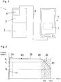
Figure 2 shows a graph of a current draw of a first electronic device receiving power from the power supply apparatus for charging a battery of the electronic device; -
Figure 3 shows a graph of a current draw of the first and a second electronic device receiving power from the power supply apparatus for charging a battery of the electronic device; -
Figure 4 shows a power supply apparatus connected to an electronic device having an in-flight mode activated. -
Figure 1 shows apower supply apparatus 1 comprising afuel cell 2 configured to receive a supply of fuel from afuel storage vessel 3 for generating electrical power. In this embodiment, thepower supply apparatus 1 is portable and thefuel storage vessel 3 is configured to be replaceable. Thepower supply apparatus 1 is shown coupled to anelectronic device 4 to supply power thereto. Theelectronic device 4 is coupled to theapparatus 1 by acable 5, such as a USB cable. It will be appreciated that theelectronic device 4 could be coupled to theapparatus 1 by an inductive coupling such that power is supplied by way of an electromagnetic field or by any other cable or power transfer means. Theapparatus 1 includes acontroller 6 configured to determine the power flow to theelectronic device 4 to interrupt the supply of power to theelectronic device 4 prior to abattery 7 of the electronic device reaching a fully charged state. The battery charge state may be reported to the apparatus by the electronic device. However, in this example, this is achieved by determining when the current flow between theapparatus 1 and theelectronic device 4 falls below an above-zero threshold current determined by saidcontroller 6. -
Figure 2 shows aplot 20 of the current drawn by theelectronic device 4 over time as thebattery 7 of theelectronic device 4 is being charged by the power received from thepower supply apparatus 1. Theelectronic device 4 is connected at t=0 and the current increases sharply over aninitial connection period 21. If thedevice 4 is connected by a USB port, theinitial connection period 21 may comprise a handshaking period when the USB device is first connected. The current reaches a substantially stable value, lc, representing a charging current after theinitial connection period 21. The charging current has been found to be relatively constant while thebattery 7 of theelectronic device 4 is being charged. Towards the end of the charging process, it has been found that the current drawn by theelectronic device 4 decreases as shown byregion 22. In this example the start of the decreasing current draw occurs at around an 85% charge level of the battery, although this may depend on the battery and type ofelectronic device 4. The current drawn by theelectronic device 4 decreases up until the battery is fully charged (marked 100%). From then, the device draws an operating current lo which powers the operation of the electronic device 4 (if active) rather than charging its battery, although, it will be appreciated that some current may be used to keep the battery at 100% charged. - The
fuel cell 2 may be configured to supply the required voltage and current, lc, efficiently. However, during the period in which there is a decrease in current draw, represented by the shadedarea 23, the fuel cell operates at a reduced efficiency. It has been found that there may be significant wastage of fuel from thefuel storage vessel 3 when theelectronic device 4 is drawing a current less than lc because the fuel cell is operating less efficiently than when supplying current lc. If the power supply apparatus is a portable device with a limited amount of fuel in thefuel storage vessel 3, it is beneficial for it to operate efficiently. - The
controller 6 may therefore be configured to control thefuel cell 2 such that it interrupts the provision of power to theelectronic device 4 before the electronic device is fully charged. The interruption may occur when the current drawn by the device falls below a threshold current, lt. In this example, with this particularelectronic device 4, the current value lt corresponds to a charge level of approximately 90% of fully charged. By interrupting the supply of power at this point, the time spent supplying power in theregion 23 is reduced therefore improving efficiency. Thus, thecontroller 6 may interrupt power generation by the fuel cell when the current draw reaches lt, leaving the battery charged to 90%. It will be appreciated that the threshold current It may alternatively be considered to correspond to a particular fuel cell efficiency. Thus, when operation of thefuel cell 2 falls below a threshold efficiency value, thecontroller 6 may interrupt the supply of power. The general shape of theplot 20 has been found to be common to many electronic devices when charging. Therefore, rather than charge the battery to a fully charged state, the controller interrupts the supply to maintain efficiency of thefuel cell 2. Although this example relates to a fuel cell power supply apparatus, the invention may be beneficial for any portable power generation device. - The controller may reconfigure the
apparatus 1 such that the supply of power is resumed at the operating current lo rather than inefficiently charging the battery. Thus, the controller may reconfigure theapparatus 1 to provide a different output voltage. The controller may be configured to monitor the current drawn by theelectronic device 4 and monitor the performance of thefuel cell 2 and select an output voltage based on these two conditions. - In a first example, the threshold current may comprise a predetermined value. Alternatively, the threshold current may be calculated by the
controller 6. In one example, the controller may determine the current draw of the electronic device during an initial period after theelectronic device 4 is connected to theapparatus 1. The initial period may comprise a period of time from the moment theapparatus 1 andelectronic device 4 are coupled. An average current draw may be calculated over the initial period. The initial period may start only when the current draw has reached a stable (within limits) value. As shown inFigure 2 , theinitial period 24 is temporally positioned such that the change in current draw on initial coupling inregion 21 is ignored. Theperiod 24 may comprise a predetermined period of time or a predetermined number of sampled measurements by thecontroller 6. - The
controller 6 may sample the current drawn over theperiod 24 to determine the "charging current" of the electronic device, comprising the substantially constant current drawn during aperiod 25 prior to theelectronic device 4 reducing its current draw inregion 22. Accordingly, the controller may determine the initial current draw as lc. The controller may then be configured, using the measured current flow, to determine the threshold current, lt. In this example, the threshold current comprises a percentage, such as 80% of the charging current lc, which the controller may calculate. Alternatively a look-up table may be provided which thecontroller 6 may consult using the measured value to determine the threshold current. - In a further example, the controller may categorise the
electronic device 4 by the measured current drawn and assign a threshold current accordingly. -
Figure 3 shows two battery charging profiles of two different electronic devices. Thefirst profile 30a comprises the profile of a mobile telephone for example. Thesecond profile 30b comprises the profile of a portable music player for example. It will be appreciated that theprofiles controller 6 is configured to measure the initial current drawn by the device using the techniques described above. Thecontroller 6 may therefore identify the first device as having a charging current draw of lc1 and the second device as having a charging current draw of lc2. Based on these values, the controller is configured to categorise the two devices in one of two classifications; a "high draw" device or a "low draw" device. The controller may have predefined current draw ranges for the purpose of classifying the device. Alternatively the controller may include a predetermined classification current wherein if the measured current is above the classification current it is classified as a "high draw" device and if the measured current is less than or equal to the classification current the device is classified as a "low draw" device. This classification approach may be advantageous as it has been found that many electronic devices charge at substantially one of two current levels. - Once the controller has classified the device, the threshold current at which charging of the device's battery is interrupted is determined. The threshold current may be predetermined based on the classification. Alternatively, the threshold current for the first category may comprise a first percentage of the measured current while the threshold current for the second category may comprise a second percentage of the measured current. It can be seen from
Figure 3 that thefirst profile 30a has a threshold current lt1 which comprises 80%, for example, of the charging current measured during theinitial period 31a. Thesecond profile 30b has a threshold current lt2 which comprises 90%, for example, of the charging current measured during theinitial period 31b. As a result of these threshold current limits, charging of the first device happens to be interrupted at approximately 90% of fully charged and charging of the second device happens to be interrupted at approximately 95% of fully charged. - In a further example, the threshold current may comprise the current reached after a predetermined period of time once a decrease in current draw (above a decrease threshold) is detected, such as a period of time after
point 26 ofFigure 2 . The decrease threshold may prevent fluctuations in the charging current starting the timer beforepoint 26 is reached. - The apparatus may be further configured to identify whether or not the power supplied to the
electronic device 4 from thefuel cell 2 is being used to charge its battery or just to operate the device. In general, the current drawn by adevice 4 that is just being operated is lower that when it is charging its battery. Thus, the controller may be configured with a further current threshold or range, which may be at a current level below the categories described above. A device drawing a current below the further current threshold is considered to be operating rather than charging its battery and therefore interruption of the power supply when the current draw falls is disabled so that the device can be operated continuously. - In a further example, the threshold current may be determined using information that identifies the
electronic device 4 which is connected to theapparatus 1. In particular, when the electronic device is connected/coupled to theapparatus 1 it may report its vendor ID and/or product ID as part of an identification message. Such an identification message may be part of a pre-existing standard, such as a USB standard or a plug and play (PnP) standard. - The
controller 6 may be configured to receive the identification message and using predetermined device-specific or device-type-specific information determine a threshold current for the electronic device. Thus, the charge profiles of devices or categories of device (mobile telephone, laptop etc.) may be predetermined and stored in a memory of the controller. The charge profiles may comprise information identifying one or more of the threshold current, the point at which the current drawn decreases, the battery charge level reached at different current draw levels or any other information about how the particular device or category of device typically receives power for charging. The controller may therefore derive the threshold current from predetermined data using the identification message. - In a further example, the
controller 6 may use a communication element to request the threshold current to use for a particular device. For example, thecontroller 6 may interrogate a server on the internet for the threshold current to use. Thecontroller 6 may use communication capabilities of theelectronic device 4 to perform this function. Thus, the electronic device may include an application or "app" that provides an interface for theapparatus 1. Accordingly, thecontroller 6 may use the interface provided by the app to download a charging profile and/or threshold current to use when supplying power to the device. - Thus, the app may be adapted to send an identification message for informing the
apparatus 1 of the type of device and/or may be adapted to send a charge profile message, informing the apparatus of the current threshold at which to interrupt the supply of power. - In a further example, the
controller 6 may be configured to automatically interrupt the supply of power to the electronic device prior to the battery of the electronic device reaching a fully charged state based on a user-selectable charge level. Thus, theelectronic device 4 may include a controller, which in this example is embodied as software as an "app" executable on theelectronic device 4, that may receive user input of a desired charge level. - The user, using the app, may be able to specify a particular charge level or select from a plurality of options, such as 10%, 20%, 30%... 70%, 80% or 90% charged. It will be appreciated that the granularity of the options as well as the minimum and maximum selectable charge levels could be other values. As a portable fuel cell
power supply apparatus 1 will have a limited supply of fuel, providing the user with a selectable option to automatically stop charging in advance of a fully charged state is advantageous as fuel can be conserved. For example, the user may only require a few hours of usage from the electronic device before they will arrive home where mains electricity is available for charging the device. Accordingly the user may determine that a 50% charge level will suffice for this period of time and their expected usage. Thus, they are able to provide a user-selectable charge level of 50% and the power supply apparatus will automatically interrupt the charging process when that charge level is reached. The app may automatically prompt the user for a desired charge level when the power supply apparatus is connected to the electronic device prior to charging commencing. - The app may be configured to communicate with the
power supply apparatus 1 or thecontroller 6 thereof to inform the power supply apparatus of the charge level selected by the user in a charge level electronic message. The message may be supplied via thecable 5. Thepower supply apparatus 1 may then decide when to interrupt the supply of power to achieve the selected charge level. Rather than an app on the electronic device, the power supply apparatus may include a user input interface, such as a keypad, for receiving user input of the desired charge level. - The
controller 6 may use a predetermined charge profile of power flow versus charge level. Thus, the charge level message may be received and the power flow level or current flow level corresponding to that charge level may be determined. The controller can then automatically interrupt the supply of power when the power flow is reached. Alternatively, the app may report the charge level to thecontroller 6 periodically and thecontroller 6 can interrupt the power supply at the appropriate time. - However, in this example, the app on the
electronic device 4 is configured to monitor the charge level of thebattery 7 during charging and determine when the charge level reaches the user selected charge level. When this occurs, the app is configured to send an interrupt supply electronic message viacable 5 to thepower supply apparatus 1 and, in response to said message, thecontroller 6 is configured to automatically interrupt the supply of power to the electronic device. It will be appreciated that while it has been stated that the messages between theelectronic device 4 andapparatus 1 are sent via thecable 5, other communication channels may be used, such as wireless communication. -
Figure 4 shows apower supply apparatus 41 similar to that shown inFigure 1 and corresponding reference numerals have been used. In this figure, theelectronic device 44 is in an in-flight mode. The use of electronic devices on aircraft is subject to restrictions. Thepower supply apparatus 41 described herein provides a convenient and portable source of electrical power and therefore it may be advantageous to control how the apparatus provides power to satisfy aircraft restrictions. - A
controller battery 47 of theelectronic device 44. The charging current is supplied viacable 45 by thepower supply apparatus 41 or, more specifically, a portable power generation apparatus having a limited energy supply. Thepower supply apparatus 41 comprises afuel cell 42 configured to receive a supply of a fuel from a replaceablefuel storage vessel 43 for generating said charging current. Thecontroller electronic device 44, said operational condition comprising whether or not saidelectronic device 44 is being used by a user, interrupt the supply of the charging current from thepower supply apparatus 41. Thus, the controller is able to prevent charging of the battery of the electronic device if it is detected that the device is not being used by the user and may therefore be unattended. - The
controller - The
fuel cell charger 42 is connected to theelectronic device 44 by a power andcommunications cable 45, such as a USB cable. Thus, theapparatus 41 can supply power for charging abattery 47 of thedevice 44, provide power for operating thedevice 44 without charging thebattery 47 and also communicate with electronic device. Thus, thepower supply apparatus 41 includes part of thecontroller 46a, which may be embodied as software and executed on a processor of theapparatus 41 or may be provided as a hard-wired controller. Theelectronic device 44 also includes a part of thecontroller 46b, which is provided as an application or "app" that is executed on theelectronic device 44. In this embodiment, the electronic device comprises a "smartphone", although, it will be appreciated that any electronic device capable of executing software for communicating with theapparatus 41 may be used. - The
controller parts fuel cell 42 to the electronic device. In a first example, thecontroller 46b reports one or more activity indicators to thecontroller 46a. The activity indicators provide thecontroller 46a with information indicative of whether thedevice 44 is being used by a user. Thus, thecontroller 46b may report one or more of; - i) processor utilisation of a processor of the
electronic device 44 - ii) display illuminator status of a
display illuminator 48 of theelectronic device 44 - iii) the receipt of user input to the
electronic device 44 - iv) detection of movement or motion from motion sensors (not shown)
- v) ambient sound levels
- The
controller 46b may therefore interrogate the operating system of the electronic device for this information. The processor utilisation may be requested by thecontroller 46b and then reported to thecontroller 46a. If processor utilisation is below a threshold value it may be considered that the device is not being actively used by a user. Accordingly, thecontroller 46a may interrupt the charging current to the device. - The status of the display may also be used as an indication of the device being used. Many
electronic devices 44 have illuminated displays, such as liquid crystal based displays. Such displays typically include adisplay illuminator 48 or backlight. Thecontroller 46b may be configured to determine the status of thedisplay illuminator 48. If the illuminator is turned off, it is indicative of thedevice 44 not being actively used. Thecontroller 46b may report the status of thedisplay illuminator 48 to thecontroller 46a for controlling the charging current. - The
controller 46b may also determine whether or not thedevice 44 is receiving user input and/or the frequency of the user input. This may be determined from button presses or interaction with a touch sensitive display. The absence of user input for a threshold period of time may be indicative of whether or not the device is in use. Thus, thecontroller 46b may report the user input frequency to thecontroller 46a. - The
controller 46b may also determine whether or not thedevice 44 is being moved using accelerometers, gyroscopic sensor or other movement sensors of theelectronic device 44. It is common for electronic devices such as mobile telephones to include accelerometers. If motion is not detected for a predetermined period of time, it may be indicative of the device not being used. Alternatively or in addition, thepower supply apparatus 41 may include motion sensors to determine information indicative of the electronic device being in use. - The
controller 46b may also determine whether or not thedevice 44 is in use by using a microphone of the electronic device to detect ambient sound levels. If the electronic device is a mobile telephone, thecontroller 46b may use an in-built microphone used for conducting calls. For example, if the ambient sound levels are below a predetermined magnitude threshold or audio threshold, it may be indicative of the electronic device being unused or stored in a bag or the like. Thecontroller 46b may analyse the sounds detected by the microphone (such as the frequency profile and/or amplitude profile) to determine if they are muffled, which may be indicative of the electronic device being located in a bag or storage bin (and therefore not in use) rather than in the open cabin of an aircraft (and therefore in use). The fuel supply apparatus may be provided with a microphone for such a purpose. - It will be appreciated that other activity indicators may be used, such as input from position or orientation sensors. For example, smartphones include a plurality of sensors and the output from these sensors, determined by
controller 46b, may be used to assess the operational status of the smartphone. - It will be appreciated that in the above paragraphs the
controller 46b is used to collect data and report that data to thecontroller 46a. However, thecontroller 46b in the electronic device may be configured to make decisions on whether the charging current should be interrupted based on the monitoring of the activity indicators. Thus, in another example, thecontroller 46b may send an instruction to thecontroller 46a to interrupt the supply of the charging current. - In a further example, a light sensor may be used to determine if the
electronic device 44 is in use. Theelectronic device 44 may be equipped with a light sensor and thecontroller 46b may determine its status. If the light level sensed by the sensor is below a threshold value, thecontroller 46b orcontroller 46a may determine that the device is not in use and therefore (subject to any other activity indicators used) interrupt the charging current. The light sensor may comprise a camera of the electronic device. For example, if the electronic device is a mobile telephone, one or both of a front facing camera or rear facing camera may be used to detect ambient light levels. The cameras may have light level meters associated therewith that are used. - Alternatively or in addition, the
power supply apparatus 41 may include alight sensor 50. Thelight sensor 50 may be used to determine if the power supply apparatus 41 (perhaps when connected to an electronic device 44) is in use or stored away. Thus, using the example of use on an aircraft, if thepower supply apparatus 41 is connected to an electronic device and is supplying a charging current to charge itsbattery 47, thecontroller 46a may use thelight sensor 50 to determine whether the device is being used in the cabin (where it would detect light) or if theapparatus 41 anddevice 44 are stowed away in an overhead bin or seat pocket (where it would detect little or no light). If thecontroller 46a determines, using thelight sensor 50, that the apparatus is in darkness (i.e. the measured light level is below a predetermined threshold) then it may interrupt the charging current (subject to any other activity indicators). - It may be advantageous to limit instances of the
fuel cell 42 interrupting the supply of the charging current to when thepower supply apparatus 41 andelectronic device 44 are being used on an aircraft. Thus, thecontroller - An in-flight mode is a common feature on many electronic devices that have wireless communication channels, such as cellular network (GSM, UMTS for example), WiFi and/or Bluetooth. The in-flight mode disables the wireless communication channels to prevent interference with the aircraft's systems. The
controller 46b may be configured to interrogate the operating system of theelectronic device 44 to determine if thedevice 44 is in an in-flight mode. Accordingly, thecontroller - In another example, the operating system of the electronic device may not be configured to report the selection status of an in-flight mode and therefore it may be necessary for the
controller 46b to assess parameters indicative of an in-flight mode. For example, thecontroller 46b, comprising an "app" in this example, is configured to request the current availability status of the communication channels of thedevice 44. The operating system of theelectronic device 44 may report that communication is not currently possible via the known communication channels of thedevice 44. Thecontroller 46b may infer from this that the user has activated the in-flight mode of theelectronic device 44. Accordingly, thecontroller - The charging current may comprise a current level (which may be particular to the
electronic device 44 and its battery 47), at which the battery is charged. It may be possible to supply power to theelectronic device 44 at a lower level which is sufficient to power the operation of theelectronic device 44 without charging thebattery 47. Thus, the interruption of the charging current may comprise reducing the power supplied by theapparatus 41 to a level where thebattery 47 is not being charged. Alternatively, the interruption of the charging current may comprise halting power transfer to theelectronic device 44. - In a further embodiment, the controller 46 is located solely in the
apparatus 41 and the operational condition is determined using thelight sensor 50, for example. - The term battery has been used to define an energy store of the electronic device. It will be appreciated that the term battery is intended to include any energy storage device, such as an electrochemical battery or a capacitor.
Claims (15)
- A power supply apparatus for providing electrical power, the power supply apparatus configured to be coupled to an electronic device to supply power thereto to charge a battery of the electronic device, the apparatus comprising a fuel cell configured to receive a supply of a fuel for generating said electrical power, the apparatus further including a controller configured to interrupt the supply of power to the electronic device prior to the battery of the electronic device reaching a fully charged state, wherein the controller is configured to interrupt the supply of power to the electronic device based on at least one of:i) when the current flow between the apparatus and the electronic device during charging of the battery falls below an above-zero threshold current determined by said controller; andii) a battery charge state reported to the power supply apparatus by the electronic device.
- A power supply apparatus according to claim 1, in which the controller is configured to determine the threshold current on coupling of the electronic device and the apparatus.
- A power supply apparatus according to claim 2, in which the controller is configured to measure the current flow to the electronic device and, based on said measured current flow, determine the threshold current.
- A power supply apparatus according to claim 3, in which the controller is configured to measure the current flow for determining the threshold current for a predetermined period from when the electronic device is coupled to the apparatus.
- A power supply apparatus according to claim 3, in which the controller is configured to, based on the measured current flow, categorise the electronic device to one of a plurality of categories, wherein each category is associated with a different threshold current.
- A power supply apparatus according to claim 1, in which the controller is configured to receive a message indicating the threshold current to use for the coupled electronic device.
- A power supply apparatus according to claim 1, in which the controller is configured to receive an identification message from the electronic device which identifies the electronic device to the controller and, using the identification message, determine the threshold current to use in supplying power to said electronic device.
- A power supply apparatus according to claim 1, in which the controller is configured to receive a charge profile message from the electronic device and, using the charge profile message, determine the threshold current to use in supplying power to said electronic device.
- A power supply apparatus according to claim 1, in which the controller is configured to determine when to interrupt the supply of power based on an efficiency level of the fuel cell failing below a predetermined efficiency level.
- A power supply apparatus according to any preceding claim, in which the apparatus is portable and configured to receive a replaceable cartridge of fuel.
- A computer program for execution on an electronic device, the computer program configured to control a fuel cell based power supply apparatus that is adapted to provide electrical power to charge a battery of the electronic device on which the computer program is executed, wherein the computer program, when executed on the electronic device is configured to;
identify the electronic device; and eitheri) send an identification message to the apparatus which identifies the electronic device to the fuel cell based power supply apparatus; orii) using the identity of the electronic device, determine a charge profile and send a charge profile message containing said charge profile to the apparatus;to thereby provide for determination by the power supply apparatus of an above-zero threshold current for interrupting the supply of power to the electronic device when the current flow between the apparatus and the electronic device falls below said above-zero threshold current and thereby prior to the battery of the electronic device reaching a fully charged state. - A power supply apparatus according to claim 1, wherein the interruption of the supply of power to the electronic device is based on a user-selectable charge level that is less than fully charged.
- A power supply apparatus according to claim 12, in which the controller is configured to receive the user-selectable charge level in a message from the electronic device.
- A power supply apparatus according to claim 13 in which the controller is configured to monitor the power supplied to the electronic device and, using a predetermined power flow profile for the electronic device and the charge level message, interrupt the supply of power when the power flow to the electronic device reaches a level equivalent to the desired charge level.
- A power supply apparatus according to claim 12 or 13, in which the controller is configured to monitor the charge level of the battery of the electronic device using a charge level message received from the electronic device which reports the charge level to the controller.
Applications Claiming Priority (2)
| Application Number | Priority Date | Filing Date | Title |
|---|---|---|---|
| GB1406242.6A GB2524973A (en) | 2014-04-07 | 2014-04-07 | Power supply apparatus |
| PCT/GB2015/050793 WO2015155499A2 (en) | 2014-04-07 | 2015-03-18 | Power supply apparatus |
Publications (2)
| Publication Number | Publication Date |
|---|---|
| EP3130054A2 EP3130054A2 (en) | 2017-02-15 |
| EP3130054B1 true EP3130054B1 (en) | 2019-09-18 |
Family
ID=50776946
Family Applications (1)
| Application Number | Title | Priority Date | Filing Date |
|---|---|---|---|
| EP15717202.4A Active EP3130054B1 (en) | 2014-04-07 | 2015-03-18 | Power supply apparatus |
Country Status (6)
| Country | Link |
|---|---|
| US (1) | US10298039B2 (en) |
| EP (1) | EP3130054B1 (en) |
| JP (1) | JP6670753B2 (en) |
| GB (1) | GB2524973A (en) |
| TW (1) | TW201603381A (en) |
| WO (1) | WO2015155499A2 (en) |
Families Citing this family (3)
| Publication number | Priority date | Publication date | Assignee | Title |
|---|---|---|---|---|
| TWI560933B (en) * | 2016-03-14 | 2016-12-01 | Nat Univ Chin Yi Technology | Power bank module utilizing light-weight proton exchange membrane fuel cell (pemfc) |
| US10614682B1 (en) * | 2019-01-24 | 2020-04-07 | Mobile Tech, Inc. | Motion sensing cable for tracking customer interaction with devices |
| KR20230061043A (en) * | 2021-10-28 | 2023-05-08 | 주식회사 엘지에너지솔루션 | A power bank having a function of providing a chargeable range of a battery pack, a battery pack charging system including the same, and a method therefor |
Family Cites Families (48)
| Publication number | Priority date | Publication date | Assignee | Title |
|---|---|---|---|---|
| US6387556B1 (en) | 1997-11-20 | 2002-05-14 | Avista Laboratories, Inc. | Fuel cell power systems and methods of controlling a fuel cell power system |
| US6979507B2 (en) * | 2000-07-26 | 2005-12-27 | Idatech, Llc | Fuel cell system controller |
| US6781343B1 (en) * | 2000-09-20 | 2004-08-24 | Honda Giken Kogyo Kabushiki Kaisha | Hybrid power supply device |
| JP3662872B2 (en) | 2000-11-17 | 2005-06-22 | 本田技研工業株式会社 | Fuel cell power supply |
| US6992401B1 (en) | 2002-11-15 | 2006-01-31 | Sprint Communications Company L.P. | Power system for a telecommunication facility |
| JP3764426B2 (en) | 2003-01-21 | 2006-04-05 | 株式会社東芝 | Electronic device and operation control method |
| JP4742486B2 (en) | 2003-04-10 | 2011-08-10 | 日産自動車株式会社 | Fuel cell power generation control device |
| JP4066901B2 (en) * | 2003-07-03 | 2008-03-26 | ソニー株式会社 | Power adapter and power supply system |
| US7482091B2 (en) * | 2003-07-09 | 2009-01-27 | The Gillette Company | Fuel cartridge interconnect for portable fuel cells |
| WO2005088326A1 (en) | 2004-03-15 | 2005-09-22 | Hydrogenics Corporation | Test station for a fuel cell power module |
| JP4410722B2 (en) * | 2005-05-06 | 2010-02-03 | 株式会社日立製作所 | Power supply |
| KR20060135142A (en) * | 2005-06-24 | 2006-12-29 | 삼성에스디아이 주식회사 | Fuel cell system and driving method thereof |
| JP4868883B2 (en) | 2006-02-23 | 2012-02-01 | Jx日鉱日石エネルギー株式会社 | Emergency power supply system using fuel cell and distribution board |
| JP2007280741A (en) * | 2006-04-06 | 2007-10-25 | Hitachi Ltd | Fuel cell device |
| JP4486618B2 (en) * | 2006-06-06 | 2010-06-23 | 株式会社リコー | Charging circuit, charging circuit operation control method, and power supply device |
| US20070285048A1 (en) * | 2006-06-12 | 2007-12-13 | Leach David H | Fuel cell charger interface with multiple voltage outputs for portable devices |
| JP2008004379A (en) * | 2006-06-22 | 2008-01-10 | Hitachi Maxell Ltd | Fuel cell system |
| US20080007212A1 (en) * | 2006-07-05 | 2008-01-10 | Logitech Europe S.A. | Universal charger |
| JP2008067496A (en) | 2006-09-07 | 2008-03-21 | Ricoh Co Ltd | Charging device and method for secondary battery |
| JP4930846B2 (en) | 2007-07-17 | 2012-05-16 | トヨタ自動車株式会社 | Fuel cell system and control method thereof |
| US8095713B2 (en) * | 2007-09-04 | 2012-01-10 | Apple Inc. | Smart cables |
| US8261102B2 (en) * | 2008-04-28 | 2012-09-04 | Delta Electronics, Inc. | Power management system capable of saving power and optimizing operating efficiency of power supplies for providing power with back-up or redundancy to plural loads |
| JP5090245B2 (en) * | 2008-05-07 | 2012-12-05 | 富士フイルム株式会社 | Electronic cassette charging device, electronic cassette charging system, and electronic cassette charging method |
| JP5344223B2 (en) * | 2009-01-23 | 2013-11-20 | ソニー株式会社 | Fuel cell system and electronic device |
| US8200292B2 (en) | 2009-02-26 | 2012-06-12 | Research In Motion Limited | Method and apparatus for dynamic battery management control in a mobile communication device |
| US8922329B2 (en) * | 2009-07-23 | 2014-12-30 | Qualcomm Incorporated | Battery charging to extend battery life and improve efficiency |
| JP2011083116A (en) | 2009-10-07 | 2011-04-21 | Nec Saitama Ltd | Mobile terminal and control method of the same |
| JP4783454B2 (en) * | 2009-11-30 | 2011-09-28 | 株式会社東芝 | Power supply device, system, and charge / discharge control method |
| WO2011118111A1 (en) | 2010-03-26 | 2011-09-29 | パナソニック株式会社 | Fuel cell system and control method therefor |
| KR20120037837A (en) | 2010-10-12 | 2012-04-20 | 삼성에스디아이 주식회사 | Fuel cell system and method for operating the same |
| TWI416788B (en) | 2010-11-03 | 2013-11-21 | Ind Tech Res Inst | Fuel cell system |
| US8639954B2 (en) * | 2010-12-20 | 2014-01-28 | Motorola Mobility Llc | Portable electronic device and method for recovering power to a rechargeable battery used therein |
| TWI431835B (en) | 2011-09-08 | 2014-03-21 | Askey Technology Jiang Su Ltd | System and method for managing battery charge/discharge |
| CN103828172A (en) * | 2011-09-22 | 2014-05-28 | 丰田自动车株式会社 | Vehicle power supply system |
| JP2013081289A (en) | 2011-10-03 | 2013-05-02 | Panasonic Corp | Power controller |
| US8769327B2 (en) * | 2011-10-04 | 2014-07-01 | Advanergy, Inc. | Battery charger management system and method for controlling a charge current by indirectly determining the type and characteristics of a battery via a current consumed by a charger |
| JP5360183B2 (en) * | 2011-10-25 | 2013-12-04 | トヨタ自動車株式会社 | Vehicle equipped with secondary battery and method for controlling vehicle equipped with secondary battery |
| EP2590256A1 (en) * | 2011-11-02 | 2013-05-08 | Belenos Clean Power Holding AG | Method for managing the operation of a hybrid system |
| IN2014DN05423A (en) * | 2011-12-09 | 2015-04-03 | Intelligent Energy Ltd | |
| KR20130101693A (en) * | 2012-03-06 | 2013-09-16 | 삼성전자주식회사 | Method and apparatus for power management in virtualization system using different operation system |
| US20130241464A1 (en) * | 2012-03-14 | 2013-09-19 | Samsung Sdi Co., Ltd. | Fuel cell hybrid system and method for charging rechargeable battery thereof |
| KR101403713B1 (en) * | 2012-04-30 | 2014-06-05 | 엘아이지넥스원 주식회사 | Dmfc fuel cell system for supplying power in quadrotor and method thereof |
| US9250665B2 (en) * | 2012-06-07 | 2016-02-02 | Apple Inc. | GPU with dynamic performance adjustment |
| US9335811B2 (en) | 2012-09-28 | 2016-05-10 | Protonex Technology Corporation | Portable electronic device carrier with electronic interface for recharging device battery |
| US20140167686A1 (en) * | 2012-12-18 | 2014-06-19 | Elngot Llc | Content download and synchronization |
| US20140195180A1 (en) * | 2013-01-04 | 2014-07-10 | 1 Oak Technologies, LLC | Electronic device power management |
| US9263912B2 (en) * | 2013-02-05 | 2016-02-16 | Dell Products, L.P. | Mitigating premature wear out of a rechargeable battery |
| KR20140125636A (en) * | 2013-04-19 | 2014-10-29 | 삼성전자주식회사 | Electronic apparatus, method for controlling charge and computer-readable recording medium |
-
2014
- 2014-04-07 GB GB1406242.6A patent/GB2524973A/en not_active Withdrawn
-
2015
- 2015-03-18 WO PCT/GB2015/050793 patent/WO2015155499A2/en active Application Filing
- 2015-03-18 JP JP2016560922A patent/JP6670753B2/en not_active Expired - Fee Related
- 2015-03-18 EP EP15717202.4A patent/EP3130054B1/en active Active
- 2015-03-18 US US15/302,267 patent/US10298039B2/en not_active Expired - Fee Related
- 2015-03-25 TW TW104109509A patent/TW201603381A/en unknown
Non-Patent Citations (1)
| Title |
|---|
| None * |
Also Published As
| Publication number | Publication date |
|---|---|
| WO2015155499A3 (en) | 2015-11-26 |
| TW201603381A (en) | 2016-01-16 |
| JP2017518013A (en) | 2017-06-29 |
| EP3130054A2 (en) | 2017-02-15 |
| US20170025875A1 (en) | 2017-01-26 |
| GB201406242D0 (en) | 2014-05-21 |
| GB2524973A (en) | 2015-10-14 |
| US10298039B2 (en) | 2019-05-21 |
| WO2015155499A2 (en) | 2015-10-15 |
| JP6670753B2 (en) | 2020-03-25 |
Similar Documents
| Publication | Publication Date | Title |
|---|---|---|
| US11201359B2 (en) | Charging control method and apparatus, and computer readable storage medium | |
| CN113346568B (en) | Method for charging battery, charging device and terminal equipment | |
| KR101545069B1 (en) | Portable electronic device and method for recovering power to a rechargeable battery used therein | |
| US20130134923A1 (en) | Apparatus, and associated method, for providing charging energy to recharge a portable power supply | |
| CN113475051B (en) | Apparatus and method for providing user interface according to wireless power sharing | |
| US8793086B2 (en) | Method and system for detecting power supply source electrical current capacity | |
| CA2796686C (en) | Apparatus, and associated method, for providing charging energy to recharge a portable power supply | |
| EP3130054B1 (en) | Power supply apparatus | |
| CN109217409B (en) | Charging method and device and electronic equipment | |
| EP2731224B1 (en) | Method for processing power source state and terminal supporting the same | |
| KR102500690B1 (en) | Battery status based charging control method and appratus thereof | |
| KR20130044924A (en) | Apparatus and mathod for controlling charge current in portable terminal | |
| CA2769143C (en) | Method and system for detecting power supply source electrical current capacity | |
| CN109217411B (en) | Charging method and device and electronic equipment | |
| KR20210089529A (en) | Wireless charging method and system for detecting invalid materials during wireless charging | |
| CN107565643B (en) | Method for starting battery charging based on power consumption detection, storage device and terminal | |
| CN116964892A (en) | Comprehensive determination of remaining charge of mobile power supply | |
| KR20120043277A (en) | Apparatus of controlling a power of a electronic device without power-off and the controlling method thereof | |
| CN114503390A (en) | Method for controlling charging of battery of electronic device and electronic device thereof | |
| KR101359091B1 (en) | Apparatus for power managing/controlling in portable electron equipment and method thereof | |
| CN211655764U (en) | Mobile power supply | |
| EP4246761A1 (en) | Electronic device for suppressing heating | |
| CN111064271A (en) | Mobile power supply and positioning method thereof | |
| KR20210101705A (en) | Method for wireless charging and electronic device supporting the same | |
| KR20190090277A (en) | System for processing information |
Legal Events
| Date | Code | Title | Description |
|---|---|---|---|
| STAA | Information on the status of an ep patent application or granted ep patent |
Free format text: STATUS: THE INTERNATIONAL PUBLICATION HAS BEEN MADE |
|
| PUAI | Public reference made under article 153(3) epc to a published international application that has entered the european phase |
Free format text: ORIGINAL CODE: 0009012 |
|
| STAA | Information on the status of an ep patent application or granted ep patent |
Free format text: STATUS: REQUEST FOR EXAMINATION WAS MADE |
|
| 17P | Request for examination filed |
Effective date: 20160930 |
|
| AK | Designated contracting states |
Kind code of ref document: A2 Designated state(s): AL AT BE BG CH CY CZ DE DK EE ES FI FR GB GR HR HU IE IS IT LI LT LU LV MC MK MT NL NO PL PT RO RS SE SI SK SM TR |
|
| AX | Request for extension of the european patent |
Extension state: BA ME |
|
| DAV | Request for validation of the european patent (deleted) | ||
| DAX | Request for extension of the european patent (deleted) | ||
| GRAP | Despatch of communication of intention to grant a patent |
Free format text: ORIGINAL CODE: EPIDOSNIGR1 |
|
| STAA | Information on the status of an ep patent application or granted ep patent |
Free format text: STATUS: GRANT OF PATENT IS INTENDED |
|
| INTG | Intention to grant announced |
Effective date: 20181106 |
|
| GRAJ | Information related to disapproval of communication of intention to grant by the applicant or resumption of examination proceedings by the epo deleted |
Free format text: ORIGINAL CODE: EPIDOSDIGR1 |
|
| STAA | Information on the status of an ep patent application or granted ep patent |
Free format text: STATUS: REQUEST FOR EXAMINATION WAS MADE |
|
| GRAS | Grant fee paid |
Free format text: ORIGINAL CODE: EPIDOSNIGR3 |
|
| STAA | Information on the status of an ep patent application or granted ep patent |
Free format text: STATUS: GRANT OF PATENT IS INTENDED |
|
| GRAP | Despatch of communication of intention to grant a patent |
Free format text: ORIGINAL CODE: EPIDOSNIGR1 |
|
| INTC | Intention to grant announced (deleted) | ||
| INTG | Intention to grant announced |
Effective date: 20190417 |
|
| RIC1 | Information provided on ipc code assigned before grant |
Ipc: H02J 7/00 20060101AFI20190405BHEP |
|
| GRAA | (expected) grant |
Free format text: ORIGINAL CODE: 0009210 |
|
| STAA | Information on the status of an ep patent application or granted ep patent |
Free format text: STATUS: THE PATENT HAS BEEN GRANTED |
|
| AK | Designated contracting states |
Kind code of ref document: B1 Designated state(s): AL AT BE BG CH CY CZ DE DK EE ES FI FR GB GR HR HU IE IS IT LI LT LU LV MC MK MT NL NO PL PT RO RS SE SI SK SM TR |
|
| REG | Reference to a national code |
Ref country code: GB Ref legal event code: FG4D |
|
| REG | Reference to a national code |
Ref country code: CH Ref legal event code: EP |
|
| REG | Reference to a national code |
Ref country code: DE Ref legal event code: R096 Ref document number: 602015038187 Country of ref document: DE |
|
| REG | Reference to a national code |
Ref country code: AT Ref legal event code: REF Ref document number: 1182448 Country of ref document: AT Kind code of ref document: T Effective date: 20191015 |
|
| REG | Reference to a national code |
Ref country code: IE Ref legal event code: FG4D |
|
| REG | Reference to a national code |
Ref country code: NL Ref legal event code: MP Effective date: 20190918 |
|
| PG25 | Lapsed in a contracting state [announced via postgrant information from national office to epo] |
Ref country code: FI Free format text: LAPSE BECAUSE OF FAILURE TO SUBMIT A TRANSLATION OF THE DESCRIPTION OR TO PAY THE FEE WITHIN THE PRESCRIBED TIME-LIMIT Effective date: 20190918 Ref country code: LT Free format text: LAPSE BECAUSE OF FAILURE TO SUBMIT A TRANSLATION OF THE DESCRIPTION OR TO PAY THE FEE WITHIN THE PRESCRIBED TIME-LIMIT Effective date: 20190918 Ref country code: SE Free format text: LAPSE BECAUSE OF FAILURE TO SUBMIT A TRANSLATION OF THE DESCRIPTION OR TO PAY THE FEE WITHIN THE PRESCRIBED TIME-LIMIT Effective date: 20190918 Ref country code: HR Free format text: LAPSE BECAUSE OF FAILURE TO SUBMIT A TRANSLATION OF THE DESCRIPTION OR TO PAY THE FEE WITHIN THE PRESCRIBED TIME-LIMIT Effective date: 20190918 Ref country code: BG Free format text: LAPSE BECAUSE OF FAILURE TO SUBMIT A TRANSLATION OF THE DESCRIPTION OR TO PAY THE FEE WITHIN THE PRESCRIBED TIME-LIMIT Effective date: 20191218 Ref country code: NO Free format text: LAPSE BECAUSE OF FAILURE TO SUBMIT A TRANSLATION OF THE DESCRIPTION OR TO PAY THE FEE WITHIN THE PRESCRIBED TIME-LIMIT Effective date: 20191218 |
|
| REG | Reference to a national code |
Ref country code: LT Ref legal event code: MG4D |
|
| PG25 | Lapsed in a contracting state [announced via postgrant information from national office to epo] |
Ref country code: AL Free format text: LAPSE BECAUSE OF FAILURE TO SUBMIT A TRANSLATION OF THE DESCRIPTION OR TO PAY THE FEE WITHIN THE PRESCRIBED TIME-LIMIT Effective date: 20190918 Ref country code: LV Free format text: LAPSE BECAUSE OF FAILURE TO SUBMIT A TRANSLATION OF THE DESCRIPTION OR TO PAY THE FEE WITHIN THE PRESCRIBED TIME-LIMIT Effective date: 20190918 Ref country code: RS Free format text: LAPSE BECAUSE OF FAILURE TO SUBMIT A TRANSLATION OF THE DESCRIPTION OR TO PAY THE FEE WITHIN THE PRESCRIBED TIME-LIMIT Effective date: 20190918 Ref country code: GR Free format text: LAPSE BECAUSE OF FAILURE TO SUBMIT A TRANSLATION OF THE DESCRIPTION OR TO PAY THE FEE WITHIN THE PRESCRIBED TIME-LIMIT Effective date: 20191219 |
|
| REG | Reference to a national code |
Ref country code: AT Ref legal event code: MK05 Ref document number: 1182448 Country of ref document: AT Kind code of ref document: T Effective date: 20190918 |
|
| PG25 | Lapsed in a contracting state [announced via postgrant information from national office to epo] |
Ref country code: PT Free format text: LAPSE BECAUSE OF FAILURE TO SUBMIT A TRANSLATION OF THE DESCRIPTION OR TO PAY THE FEE WITHIN THE PRESCRIBED TIME-LIMIT Effective date: 20200120 Ref country code: EE Free format text: LAPSE BECAUSE OF FAILURE TO SUBMIT A TRANSLATION OF THE DESCRIPTION OR TO PAY THE FEE WITHIN THE PRESCRIBED TIME-LIMIT Effective date: 20190918 Ref country code: AT Free format text: LAPSE BECAUSE OF FAILURE TO SUBMIT A TRANSLATION OF THE DESCRIPTION OR TO PAY THE FEE WITHIN THE PRESCRIBED TIME-LIMIT Effective date: 20190918 Ref country code: PL Free format text: LAPSE BECAUSE OF FAILURE TO SUBMIT A TRANSLATION OF THE DESCRIPTION OR TO PAY THE FEE WITHIN THE PRESCRIBED TIME-LIMIT Effective date: 20190918 Ref country code: ES Free format text: LAPSE BECAUSE OF FAILURE TO SUBMIT A TRANSLATION OF THE DESCRIPTION OR TO PAY THE FEE WITHIN THE PRESCRIBED TIME-LIMIT Effective date: 20190918 Ref country code: RO Free format text: LAPSE BECAUSE OF FAILURE TO SUBMIT A TRANSLATION OF THE DESCRIPTION OR TO PAY THE FEE WITHIN THE PRESCRIBED TIME-LIMIT Effective date: 20190918 Ref country code: NL Free format text: LAPSE BECAUSE OF FAILURE TO SUBMIT A TRANSLATION OF THE DESCRIPTION OR TO PAY THE FEE WITHIN THE PRESCRIBED TIME-LIMIT Effective date: 20190918 Ref country code: IT Free format text: LAPSE BECAUSE OF FAILURE TO SUBMIT A TRANSLATION OF THE DESCRIPTION OR TO PAY THE FEE WITHIN THE PRESCRIBED TIME-LIMIT Effective date: 20190918 |
|
| PG25 | Lapsed in a contracting state [announced via postgrant information from national office to epo] |
Ref country code: SM Free format text: LAPSE BECAUSE OF FAILURE TO SUBMIT A TRANSLATION OF THE DESCRIPTION OR TO PAY THE FEE WITHIN THE PRESCRIBED TIME-LIMIT Effective date: 20190918 Ref country code: SK Free format text: LAPSE BECAUSE OF FAILURE TO SUBMIT A TRANSLATION OF THE DESCRIPTION OR TO PAY THE FEE WITHIN THE PRESCRIBED TIME-LIMIT Effective date: 20190918 Ref country code: IS Free format text: LAPSE BECAUSE OF FAILURE TO SUBMIT A TRANSLATION OF THE DESCRIPTION OR TO PAY THE FEE WITHIN THE PRESCRIBED TIME-LIMIT Effective date: 20200224 Ref country code: CZ Free format text: LAPSE BECAUSE OF FAILURE TO SUBMIT A TRANSLATION OF THE DESCRIPTION OR TO PAY THE FEE WITHIN THE PRESCRIBED TIME-LIMIT Effective date: 20190918 |
|
| REG | Reference to a national code |
Ref country code: DE Ref legal event code: R097 Ref document number: 602015038187 Country of ref document: DE |
|
| PLBE | No opposition filed within time limit |
Free format text: ORIGINAL CODE: 0009261 |
|
| STAA | Information on the status of an ep patent application or granted ep patent |
Free format text: STATUS: NO OPPOSITION FILED WITHIN TIME LIMIT |
|
| PG2D | Information on lapse in contracting state deleted |
Ref country code: IS |
|
| PG25 | Lapsed in a contracting state [announced via postgrant information from national office to epo] |
Ref country code: DK Free format text: LAPSE BECAUSE OF FAILURE TO SUBMIT A TRANSLATION OF THE DESCRIPTION OR TO PAY THE FEE WITHIN THE PRESCRIBED TIME-LIMIT Effective date: 20190918 Ref country code: IS Free format text: LAPSE BECAUSE OF FAILURE TO SUBMIT A TRANSLATION OF THE DESCRIPTION OR TO PAY THE FEE WITHIN THE PRESCRIBED TIME-LIMIT Effective date: 20200119 |
|
| 26N | No opposition filed |
Effective date: 20200619 |
|
| PG25 | Lapsed in a contracting state [announced via postgrant information from national office to epo] |
Ref country code: SI Free format text: LAPSE BECAUSE OF FAILURE TO SUBMIT A TRANSLATION OF THE DESCRIPTION OR TO PAY THE FEE WITHIN THE PRESCRIBED TIME-LIMIT Effective date: 20190918 |
|
| REG | Reference to a national code |
Ref country code: DE Ref legal event code: R119 Ref document number: 602015038187 Country of ref document: DE |
|
| PG25 | Lapsed in a contracting state [announced via postgrant information from national office to epo] |
Ref country code: MC Free format text: LAPSE BECAUSE OF FAILURE TO SUBMIT A TRANSLATION OF THE DESCRIPTION OR TO PAY THE FEE WITHIN THE PRESCRIBED TIME-LIMIT Effective date: 20190918 |
|
| REG | Reference to a national code |
Ref country code: CH Ref legal event code: PL |
|
| REG | Reference to a national code |
Ref country code: BE Ref legal event code: MM Effective date: 20200331 |
|
| PG25 | Lapsed in a contracting state [announced via postgrant information from national office to epo] |
Ref country code: LU Free format text: LAPSE BECAUSE OF NON-PAYMENT OF DUE FEES Effective date: 20200318 |
|
| PG25 | Lapsed in a contracting state [announced via postgrant information from national office to epo] |
Ref country code: IE Free format text: LAPSE BECAUSE OF NON-PAYMENT OF DUE FEES Effective date: 20200318 Ref country code: DE Free format text: LAPSE BECAUSE OF NON-PAYMENT OF DUE FEES Effective date: 20201001 Ref country code: CH Free format text: LAPSE BECAUSE OF NON-PAYMENT OF DUE FEES Effective date: 20200331 Ref country code: FR Free format text: LAPSE BECAUSE OF NON-PAYMENT OF DUE FEES Effective date: 20200331 Ref country code: LI Free format text: LAPSE BECAUSE OF NON-PAYMENT OF DUE FEES Effective date: 20200331 |
|
| PG25 | Lapsed in a contracting state [announced via postgrant information from national office to epo] |
Ref country code: BE Free format text: LAPSE BECAUSE OF NON-PAYMENT OF DUE FEES Effective date: 20200331 |
|
| GBPC | Gb: european patent ceased through non-payment of renewal fee |
Effective date: 20200318 |
|
| PG25 | Lapsed in a contracting state [announced via postgrant information from national office to epo] |
Ref country code: GB Free format text: LAPSE BECAUSE OF NON-PAYMENT OF DUE FEES Effective date: 20200318 |
|
| PG25 | Lapsed in a contracting state [announced via postgrant information from national office to epo] |
Ref country code: TR Free format text: LAPSE BECAUSE OF FAILURE TO SUBMIT A TRANSLATION OF THE DESCRIPTION OR TO PAY THE FEE WITHIN THE PRESCRIBED TIME-LIMIT Effective date: 20190918 Ref country code: MT Free format text: LAPSE BECAUSE OF FAILURE TO SUBMIT A TRANSLATION OF THE DESCRIPTION OR TO PAY THE FEE WITHIN THE PRESCRIBED TIME-LIMIT Effective date: 20190918 Ref country code: CY Free format text: LAPSE BECAUSE OF FAILURE TO SUBMIT A TRANSLATION OF THE DESCRIPTION OR TO PAY THE FEE WITHIN THE PRESCRIBED TIME-LIMIT Effective date: 20190918 |
|
| PG25 | Lapsed in a contracting state [announced via postgrant information from national office to epo] |
Ref country code: MK Free format text: LAPSE BECAUSE OF FAILURE TO SUBMIT A TRANSLATION OF THE DESCRIPTION OR TO PAY THE FEE WITHIN THE PRESCRIBED TIME-LIMIT Effective date: 20190918 |