EP3129752B1 - System zur steuerung der einlassluft - Google Patents
System zur steuerung der einlassluft Download PDFInfo
- Publication number
- EP3129752B1 EP3129752B1 EP15717088.7A EP15717088A EP3129752B1 EP 3129752 B1 EP3129752 B1 EP 3129752B1 EP 15717088 A EP15717088 A EP 15717088A EP 3129752 B1 EP3129752 B1 EP 3129752B1
- Authority
- EP
- European Patent Office
- Prior art keywords
- damper
- duct
- transducer
- flow
- foot
- Prior art date
- Legal status (The legal status is an assumption and is not a legal conclusion. Google has not performed a legal analysis and makes no representation as to the accuracy of the status listed.)
- Active
Links
Images



Classifications
-
- G—PHYSICS
- G01—MEASURING; TESTING
- G01F—MEASURING VOLUME, VOLUME FLOW, MASS FLOW OR LIQUID LEVEL; METERING BY VOLUME
- G01F1/00—Measuring the volume flow or mass flow of fluid or fluent solid material wherein the fluid passes through a meter in a continuous flow
- G01F1/66—Measuring the volume flow or mass flow of fluid or fluent solid material wherein the fluid passes through a meter in a continuous flow by measuring frequency, phase shift or propagation time of electromagnetic or other waves, e.g. using ultrasonic flowmeters
-
- F—MECHANICAL ENGINEERING; LIGHTING; HEATING; WEAPONS; BLASTING
- F24—HEATING; RANGES; VENTILATING
- F24F—AIR-CONDITIONING; AIR-HUMIDIFICATION; VENTILATION; USE OF AIR CURRENTS FOR SCREENING
- F24F11/00—Control or safety arrangements
- F24F11/70—Control systems characterised by their outputs; Constructional details thereof
- F24F11/72—Control systems characterised by their outputs; Constructional details thereof for controlling the supply of treated air, e.g. its pressure
- F24F11/74—Control systems characterised by their outputs; Constructional details thereof for controlling the supply of treated air, e.g. its pressure for controlling air flow rate or air velocity
-
- F—MECHANICAL ENGINEERING; LIGHTING; HEATING; WEAPONS; BLASTING
- F16—ENGINEERING ELEMENTS AND UNITS; GENERAL MEASURES FOR PRODUCING AND MAINTAINING EFFECTIVE FUNCTIONING OF MACHINES OR INSTALLATIONS; THERMAL INSULATION IN GENERAL
- F16K—VALVES; TAPS; COCKS; ACTUATING-FLOATS; DEVICES FOR VENTING OR AERATING
- F16K1/00—Lift valves or globe valves, i.e. cut-off apparatus with closure members having at least a component of their opening and closing motion perpendicular to the closing faces
- F16K1/16—Lift valves or globe valves, i.e. cut-off apparatus with closure members having at least a component of their opening and closing motion perpendicular to the closing faces with pivoted closure-members
- F16K1/18—Lift valves or globe valves, i.e. cut-off apparatus with closure members having at least a component of their opening and closing motion perpendicular to the closing faces with pivoted closure-members with pivoted discs or flaps
- F16K1/22—Lift valves or globe valves, i.e. cut-off apparatus with closure members having at least a component of their opening and closing motion perpendicular to the closing faces with pivoted closure-members with pivoted discs or flaps with axis of rotation crossing the valve member, e.g. butterfly valves
- F16K1/221—Lift valves or globe valves, i.e. cut-off apparatus with closure members having at least a component of their opening and closing motion perpendicular to the closing faces with pivoted closure-members with pivoted discs or flaps with axis of rotation crossing the valve member, e.g. butterfly valves specially adapted operating means therefor
-
- F—MECHANICAL ENGINEERING; LIGHTING; HEATING; WEAPONS; BLASTING
- F16—ENGINEERING ELEMENTS AND UNITS; GENERAL MEASURES FOR PRODUCING AND MAINTAINING EFFECTIVE FUNCTIONING OF MACHINES OR INSTALLATIONS; THERMAL INSULATION IN GENERAL
- F16K—VALVES; TAPS; COCKS; ACTUATING-FLOATS; DEVICES FOR VENTING OR AERATING
- F16K37/00—Special means in or on valves or other cut-off apparatus for indicating or recording operation thereof, or for enabling an alarm to be given
- F16K37/0025—Electrical or magnetic means
-
- G—PHYSICS
- G05—CONTROLLING; REGULATING
- G05D—SYSTEMS FOR CONTROLLING OR REGULATING NON-ELECTRIC VARIABLES
- G05D7/00—Control of flow
- G05D7/06—Control of flow characterised by the use of electric means
- G05D7/0617—Control of flow characterised by the use of electric means specially adapted for fluid materials
- G05D7/0629—Control of flow characterised by the use of electric means specially adapted for fluid materials characterised by the type of regulator means
- G05D7/0635—Control of flow characterised by the use of electric means specially adapted for fluid materials characterised by the type of regulator means by action on throttling means
-
- F—MECHANICAL ENGINEERING; LIGHTING; HEATING; WEAPONS; BLASTING
- F24—HEATING; RANGES; VENTILATING
- F24F—AIR-CONDITIONING; AIR-HUMIDIFICATION; VENTILATION; USE OF AIR CURRENTS FOR SCREENING
- F24F13/00—Details common to, or for air-conditioning, air-humidification, ventilation or use of air currents for screening
- F24F13/08—Air-flow control members, e.g. louvres, grilles, flaps or guide plates
- F24F13/10—Air-flow control members, e.g. louvres, grilles, flaps or guide plates movable, e.g. dampers
- F24F13/14—Air-flow control members, e.g. louvres, grilles, flaps or guide plates movable, e.g. dampers built up of tilting members, e.g. louvre
- F24F13/1426—Air-flow control members, e.g. louvres, grilles, flaps or guide plates movable, e.g. dampers built up of tilting members, e.g. louvre characterised by actuating means
- F24F2013/1433—Air-flow control members, e.g. louvres, grilles, flaps or guide plates movable, e.g. dampers built up of tilting members, e.g. louvre characterised by actuating means with electric motors
-
- G—PHYSICS
- G01—MEASURING; TESTING
- G01F—MEASURING VOLUME, VOLUME FLOW, MASS FLOW OR LIQUID LEVEL; METERING BY VOLUME
- G01F1/00—Measuring the volume flow or mass flow of fluid or fluent solid material wherein the fluid passes through a meter in a continuous flow
- G01F1/66—Measuring the volume flow or mass flow of fluid or fluent solid material wherein the fluid passes through a meter in a continuous flow by measuring frequency, phase shift or propagation time of electromagnetic or other waves, e.g. using ultrasonic flowmeters
- G01F1/662—Constructional details
-
- G—PHYSICS
- G01—MEASURING; TESTING
- G01F—MEASURING VOLUME, VOLUME FLOW, MASS FLOW OR LIQUID LEVEL; METERING BY VOLUME
- G01F15/00—Details of, or accessories for, apparatus of groups G01F1/00 - G01F13/00 insofar as such details or appliances are not adapted to particular types of such apparatus
- G01F15/18—Supports or connecting means for meters
Definitions
- the present invention relates to a system for control of a flow of a media in a duct, which duct comprises means for flow measurement, which duct comprises means for flow regulation, which system comprises a control system, which control system receives at least input from the flow measurement, which control system controls at least one regulation damper.
- the granted Danish patent PA 2012 70241 discloses a system and a method for measuring flow in a flow duct, comprising at least two ultra sound transducers. It is the object of this Danish patent application to measure the flow of air in a duct by one or more transducers transmitting beams of ultra sound controlled by a microcontroller based electronic system. The object can be achieved if the microcontroller stores a vector of data samples for each direction of transmission, which vector comprises an appropriate number of N samples forming a frame, which microcontroller multiply each value of the frame which a complex number, which microcontroller based on the result calculates the flow in the duct.
- an efficient flow measurement of air flowing in a duct can be achieved.
- DE10001165A1 discloses a system for controlling the flow of media in a duct, wherein the controller, pressure sensors and signalling lines are arranged on a printed circuit board. However the position detection means is located at the damper location, leading to a less compact system.
- the object can be achieved by a system as disclosed in claim
- the flow measurement and the damper control are performed by a common control system, which control system comprises at least one common printed board, which printed board comprises at least one processor, which printed board further comprises a magnetic position detection means for detecting the actual position of the damper by means of at least one magnet on the damper, with the magnetic position detection means being placed on the printed circuit board.
- the air flow is probably generated by one or more large blowing means and then is more or less a common air flow sent through relative large ducts towards different inlet openings.
- changes in air flow from one outlet, maybe by manual adjustment, will have some influence at the air flow in other parts of the same system. Therefore in a traditional air condition system the air flow into each single air inlet is adjusted once and any adjustment according to the actual demand because of changes of the atmosphere of a room is difficult to achieve.
- the damper can adjust the actual flow it is possible by communication from the common processor towards a central control system to directly inform the need for actual air in the room at a sufficient moment. Therefore, a background system that comprises larger air blow systems can get information of the demand for air flow for each single outlet and it is possible also to control the larger system and thereby increase the effectivity and reduce the energy consumption.
- the means for flow measurement comprise at least a pair of ultrasound transducers for generating at least one path of ultrasound partly in the flow direction and partly against the flow direction in a channel.
- Flow measurement performed by ultrasonic method is one of the more effective ways of measuring air flow. Especially by using a path first in one direction and then in the second opposite direction it is possible by measurement of the difference in time delay to achieve information about a flow velocity. Depending on the size of the duct it can be possible to use a plurality of ultrasonic transducers and then generate a number of tracks of ultrasound in order to measure the flow in different areas of a duct.
- the position detection means for detecting the actual position of the damper be achieved by a rotatable shaft carrying the damper, which shaft further comprises indication means, which indication means cooperates with at least one detector, which detector is placed at the common printed board.
- the damper opening is important in a HVAC (Heating, Ventilation and Air Conditioning.) systems for minimizing power loss.
- the common ventilator speed is reduced until one damper in the system is close to its full opening, hereby is the power loss in the HVAC system minimized.
- the damper be formed as a linear movable damper, which linear movable damper comprises at least one toothed bar, which toothed bar is by one or more tooth wheels activating indicator means, which indication means cooperates with at least one detector, which detector is placed at the common printed board.
- a linear damper be used instead of a damper that is rotated around a shaft. In that way by for example a tooth in combination with one or more tooth wheels can be used for position detection.
- Position detection is by magnetic technology.
- the transducers be placed in transducer housing, which transducer housing is placed in an opening in a transducer foot, which transducer foot is placed in an opening in a duct, which transducer foot has an outer shape that follows openings in duct having different diameters. Forming a standard foot having sufficient height of the foot it is possible that this foot could be used in ducts having different diameters. Maybe starting by a flat surface and accepting into a relative small diameter for a duct the same transducer foot could be possible. This transducer foot will probably be moulded in a rather flexible material so that the transducer foot will be able to more or less be air tight when it is filling out the opening.
- the transducer foot comprise at least one first protrusion for interacting with the inner surface of the duct, which transduce foot further comprises a second protrusion for interacting with the outer surface of the duct, which second protrusion comprises at least one fastening means for fastening the transducer foot to the duct.
- the fastening means could be as primitive as a pop rivet or maybe a screw. Other possibilities for fastening are also possible.
- the transducer be paced inside the transducer foot, which transducer food is moulded partly around the transducer by low pressure moulding. In that way it is possible that the transducer foot is moulded around the transducer. This will be a highly effective way of producing two different foots for transducers, one to each side of a duct. The duct as such can be pre-produced having the cut outs for the transducer foots.
- the damper position detection means be formed by a Wheatstone bridge, which Wheatstone bridge comprises at least two magneto resistive resistors placed perpendicular to each other for detecting the position of a magnet, which magnet follows the position of the damper.
- the use of Wheatstone bridge gives the possibility that a rather effective measurement can be performed of the position of a magnet. In one situation it can be achieved that one of the signals is used as a sinus signal where the other signal is used as a cosine signal. In that way can be achieved that normal triangulation can be used which is effective and easily achieved in a processor to find the correct position of the damper.
- Hall elements which are likewise sensitive to the direction of the magnetic field.
- the magneto resistive is sensitive to the magnetic field direction, but not on the polarity.
- the pending patent application also concerns use of a system as disclosed previously whereby the system is used to control inlet of air into rooms, which inlet air is used for air condition or heating of the room.
- each single air inlet is controlled by both the measurement of the flow and a regulation damper.
- the correct air flow be achieved through every single air inlet in large building systems.
- each of the inlet control systems is communicating with a master control system so that set points could be generated centrally. In that way can be achieved that air for air condition or heating can be centrally regulated and in that way adjusted into the actual situation and the actual request for fresh air. This can lead to rather big savings in energy consumption in larger buildings.
- the blade has a turning, circular blade.
- the blade is steeples adjustable 0-90°.
- the dampers can be manually adjusted or motor driven. Here only the motor driven damper is considered.
- the combined controller, motor, gear, flow meter, position monitor and damper can be placed on top of the blade damper.
- a magnet on the shaft shall give the blade angle to a magnetic sensor placed on the circuit board adjacent to the microcontroller. Therefore the shaft must go all the way through the gear so the magnet can be placed on top of the blade axle just under the circuit board.
- the position sensor is a pair of magneto resistive sensors capable to give a voltage proportional to the field strength in the sensor direction. By having two sensors orthogonal to each other the angle can be calculated and the opening determined.
- the noise from the gear shall be low, under 25 dBA in 1m distance from the damper. It means that the motor shall be rather slow running and the first gear wheels may be in PA or there must be other means for preventing noise.
- the blade must turn one quarter of a revolution in 150 seconds or 0.1 revolutions per minute. Output torque shall be minimum 5 Nm.
- the regulation can be performed by a piston which can move back and forth in the perforated tube creating more or less resistance to the airflow.
- the setting in the shown box is actually done by pulling in strings connected to the piston until the flow is as desired.
- a controller keeping the flow either constant or changed after demand shall be applied to the existent box.
- a flow meter combined with an electric motor shall be mounted to set the position of the piston. If the flow is under demand the piston is moved toward the centre of the box activating more holes in the perforated tubes. Opposite if higher than demand the piston is moved away from the centre.
- the piston includes means for preventing it from turning.
- the spindle and nut will have threads with elevation 1.25 mm per revolution.
- the velocity of the piston shall be 1 mm per second.
- the turning rate of the spindle shall be 48 revolutions per minute.
- the friction of bearings and piston shall be kept low because of the low power of the motor.
- the position of the piston shall be measured by the controlling electronic.
- Fig. 1 discloses a possible embodiment for a system 2 comprising a duct 4 in which duct ultrasound transducers 6, 8 are generating beams of ultrasound between the transducers.
- the transducers 6, 8 are connecting by wiring 7, 9 towards a common printed circuit board 17.
- the system 2 further comprises a damper 10, which by a shaft 14 can be rotated by a servo motor 12, which servo motor 12 is connected by wiring 13 to the printed circuit board 17.
- the servo motor is placed on a cup 18 to allow space for insulation of the duct 4.
- magnetic means 21 are fastened to the shaft 14 and placed very near the printed circuit board so that magnetic detection means are able to detect the position of the damper 10.
- the electronic circuit 16, which is mounted at the printed board 17.
- This electronic circuit 16 is connected by a communication line 22, which for example could be RS485 MODBUS. Further is indicated a connection wiring 20 comprising single wirings 24 which is a power connection to a 24 volt AC supply where the line 26 indicates the position of the damper which could be performed as an analog voltage between 2-10 volt. Further is the line 28 indicating a set point for the air flow which also is communicated as an analog value between 2-10 volt. The line 30 is indicating a ground connection. Further is indicated wireless communication 32 which in a possible embodiment for the invention is an 868 MHz radio communication line. In operation will the system 2 be able to measure the actual flow in the duct 4 by the ultrasonic transducers 6, 8.
- the electronic circuit 16 placed at the common printed board 17 performs the total analysis of the difference in transmission period from one transducer to the other and reverse transmission. This delay time and difference in delay times is necessary for indicating the flow. Probably is from outside received an indication about the wanted flow in the duct 4 and the system is therefore automatically adjusting the damper 10 by the servo motor 12 onto a flow that is as close as possible to the wanted set point.
- Fig. 2 discloses an alternative embodiment which only differences is that the electronic circuit 16 placed at circuit board 17 is now placed at the same side of the duct as the servo motor 12. Further is indicated that magnetic means 21are fastened to the shaft 14 and placed very near the printed circuit board so that magnetic detection means are able to detect the position of the damper 10.
- Fig. 3 discloses a possible invention for fixation of a transducer 106 in the fastening means 134. Further is indicated the wiring 107.
- the fastening means 134 is probably formed in a soft material so that the fixture 134 can be placed in an opening in a duct and the outer form of the soft material is formed so it is difficult to remove the fixture.
- Using a soft material for fixation of an ultrasound transducer 106 gives the benefit that mechanical vibrations are widely damped in the soft fixture 134 and in that way not further transmitted into the duct where ultrasonic mechanical vibrations can be transmitted towards the other transducer 108 and in that way interfere with the received signal which makes precise measurement impossible.
- Fig. 4 shows a possible embodiment for a transducer foot 140 which is adapted to be used in ducts 104, 104a with different diameters.
- Fig. 5 shows section of ducts 104, 104a with different diameters.
- a transducer housing 135 with a transducer foot 140 is placed in opening in the ducts 104, 104a.
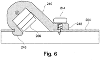
- Fig. 6 shows a possible embodiment for the invention where a duct 204 comprises a media, for example air, where the velocity has to be measured by a pair of ultrasound transducers such as 206, which transducer 206 is placed in a transducer foot 240.
- This transducer foot 204 comprises a first protrusion 246 which is performing an inner fixation of the transducer foot 240.
- a protrusion 248 which is placed at the outer side of the duct 204.
- the protrusion 248 comprises fastening means 244 such as screw or maybe pop rivet Other kinds of fastening means could also be used.
- the transducer foot 240 formed of a relative soft melt material which is isolating the mechanical vibrations generated by the transducers 206.
- Fig. 7 shows a box damper 302, which box damper in combination with an inlet 310 indicates ultrasound transducers 306 and 308. Communication lines 307, 309 are leading to a control device (not shown). The box itself is indicated as 312.
- Fig. 8 shows same embodiment as at fig. 7 , but seen from the opposite end.
- the inlet 310 together with one of the transducers 306 can be seen together with the two communication lines 307 and 309, which are connected to an electronic control device 314.
- This electronic control device 314 takes care of the calculation of the flow based on signals from the ultrasound transducers 306,308 and also for regulation of actual flow through the box 312.
- Fig. 9 shows a sectional view of same embodiment as indicated at fig. 7.
- Fig. 9 shows the two ultrasound transducers 306, 308 and the two communication lines 307 and 309. Further is indicated the inlet 310 into the box 312, which box has an outlet 316.
- the electronic device 314 comprises an electro motor, which motor is rotating a spindle 318 which spindle 318 is moving a piston 322 linearly inside a perforated tube 320 hereby regulating the flow of air through the box 312.
- FIG. 10 shows an alternative embodiment for a blade damper.
- a tube 402 has an inlet 410.
- This tube comprises ultrasound transducers 406 and 408. These transducers are connected by wiring 407 and 409 towards the control box 414.
- This control box is able to rotate a spindle 418 to which spindle blade 422 is fixed. In that way a spindle 418 can regulate the flow through the tube.
- Fig. 11 shows the electronic control box 502 comprising a motor unit 504 in which a gear box (not shown) is driving a first spindle 506 for a box damper regulation indicating one further spindle 508 for a blade damper, which further comprises magnets 510 for position sensors. Further is indicated at for example a printed circuit board, a micro-processor 506 together with a plurality of other electronic components. The micro-processor controls the rotation of the motor 504 and receives input from sensors 510 and from not shown ultrasound transducers. In that way one common control circuit can be used for as well regulation of a damper and in the same way measuring actual flow through a tube. Further is achieved that the same electronic control device can be used for two different types of dampers. Fast rotating spindle 506 is more or less directly coupled to the motor 504, but a rather complicated gearing, probably comprising several gear wheels, are necessary to reach the very slow rotating shaft 508 for blade damping.
Landscapes
- Engineering & Computer Science (AREA)
- General Engineering & Computer Science (AREA)
- Physics & Mathematics (AREA)
- Mechanical Engineering (AREA)
- Fluid Mechanics (AREA)
- Chemical & Material Sciences (AREA)
- Combustion & Propulsion (AREA)
- General Physics & Mathematics (AREA)
- Electromagnetism (AREA)
- Automation & Control Theory (AREA)
- Air-Flow Control Members (AREA)
- Measuring Volume Flow (AREA)
Claims (12)
- System (2) zur Steuerung einer Strömung eines Mediums in einem Kanal (4, 104, 104A), welcher Kanal Mittel zur Strömungsmessung (6, 8) umfasst, welcher Kanal Mittel zur Strömungsregelung (10) umfasst, welches System (2) ein Steuersystem (16) umfasst, welches Steuersystem (16) dazu ausgelegt ist, zumindest eine Eingabe von dem Strömungsmessmittel (6, 8) zu empfangen, welches Steuersystem (16) dazu ausgelegt ist, eine Steuerung mindestens eines Regeldämpfers (10) durchzuführen, wobei die Strömungsmessung und die Dämpfer-(10)-Steuerung von einem gemeinsamen Steuersystem (16) durchgeführt werden, welches Steuersystem (16) mindestens eine gemeinsame Leiterplatte (17) umfasst, welche Leiterplatte (17) mindestens einen Prozessor umfasst, dadurch gekennzeichnet, dass die Leiterplatte (17) ferner ein magnetisches Positionserfassungsmittel zur Erfassung der aktuellen Position des Dämpfers (10) mittels mindestens eines Magneten (21) am Dämpfer umfasst, wobei das magnetische Positionserfassungsmittel auf der Leiterplatte (17) angeordnet ist.
- System nach Anspruch 1, dadurch gekennzeichnet, dass das Mittel zur Strömungsmessung mindestens ein Paar von Ultraschallwandlern (6, 8) zur Erzeugung mindestens eines Ultraschallweges teilweise in der Strömungsrichtung und teilweise entgegen der Strömungsrichtung im Kanal (4, 104, 104a) umfasst.
- System nach Anspruch 2, dadurch gekennzeichnet, dass die Ultraschallwandler (6,8) mit einer Senderschaltung und mit einer Empfängerschaltung verbunden sind, welche Empfängerschaltung mindestens ein Anti-Aliasing-Filter umfasst, welches Anti-Aliasing-Filter außerdem mit einem Mikrocontroller verbunden ist, welcher Mikrocontroller entweder intern oder extern einen Anälog-Digital-Wandler umfasst, welcher Digital-Wandler zur Umwandlung des analogen Signals in digitale Datenproben, die zumindest Laufzeiten und Zeitdifferenz darstellen, ausgelegt ist, welcher Mikrocontroller dazu ausgelegt ist, die Datenproben in einem Speicher zu speichern, wobei eine Senderschaltung und eine Empfängerschaltung durch einen Schalter gesteuert werden, welcher Schalter dazu ausgelegt ist, eine kontinuierliche Umschaltung der Senderschaltung in eine Empfängerschaltung und die Empfängerschaltung in eine Senderschaltung durchzuführen, welcher Mikrocontroller dazu ausgelegt ist, einen Vektor einer Datenprobe für jede Übertragungsrichtung zu speichern, welcher Vektor eine geeignete Anzahl von einen Rahmen bildenden N-Proben umfasst, welcher Mikrocontroller dazu ausgelegt ist, jeden Wert des Rahmens mit einer komplexen Zahl mit fester Größe und einer Phase zu multiplizieren, die übertragene Frequenz darstellend, die dem übertragenen Signal entspricht:

- System nach Anspruch 1, dadurch gekennzeichnet, dass das magnetische Positionserfassungsmittel zum Erfassen der aktuellen Position des Dämpfers (10) durch eine den Dämpfer (10) tragende drehbare Welle (14) erreicht wird, welche Welle ferner ein Anzeigemittel umfasst, das der Magnet ist, welcher Magnet zum Zusammenwirken mit dem auf der Leiterplatte (17) angeordneten magnetischen Positionserfassungsmittel ausgelegt ist.
- System nach Anspruch 1, dadurch gekennzeichnet, dass der Dämpfer (10) als linearer beweglicher Dämpfer ausgebildet ist, welcher lineare bewegliche Dämpfer mindestens eine Zahnstange umfasst, welche Zahnstange durch ein oder mehrere Zahnräder aktivierendes Anzeigemittel ist, welches Anzeigemittel zum Zusammenwirken mit dem auf der Leiterplatte (17) angeordneten magnetischen Positionserfassungsmittel ausgelegt ist.
- System nach Anspruch 1 oder 5, dadurch gekennzeichnet, dass der Dämpfer als Kastendämpfer ausgebildet ist, welcher Kastendämpfer mindestens ein Lochrohr umfasst, in welchem Lochrohr ein Kolben durch einen durch eine rotierende Spindel gebildeten Linearaktor bewegt wird.
- System nach Anspruch 3, dadurch gekennzeichnet, dass die Wandler (6, 8) in einem Wandlergehäuse (134, 240) mit einem Wandlerfuß (140, 240) untergebracht sind, welcher Wandlerfuß (140, 240) eine Öffnung umfasst, in welcher ein Wandler (6, 8) angeordnet ist, welcher Wandlerfuß (140, 240) in einer Öffnung in einem Kanal (4, 104, 104a) angeordnet ist, welcher Wandlerfuß (140, 240) eine Außenform aufweist, die Öffnungen in dem Kanal (4, 104, 104a) mit unterschiedlichen Durchmessern folgt.
- System nach Anspruch 7, dadurch gekennzeichnet, dass der Wandlerfuß (240) zumindest einen ersten Vorsprung (246) zum Zusammenwirken mit der Innenfläche des Kanals (204) umfasst, welcher Wandlerfuß (240) ferner einen zweiten Vorsprung (248) zum Zusammenwirken mit der Außenfläche des Kanals (204) umfasst, welcher zweite Vorsprung (248) zumindest ein Befestigungsmittel (244) zur Befestigung des Wandlerfußes (240) an dem Kanal (204) umfasst.
- System nach Anspruch 7 oder 8, dadurch gekennzeichnet, dass der Wandler (206) innerhalb des Wandlerfußes (240) angeordnet ist, welcher Wandlerfuß (240) teilweise um den Wandler (206) durch Niederdruckformen geformt ist.
- System nach einem der Ansprüche 1 - 9, dadurch gekennzeichnet, dass das magnetische Dämpferpositionserfassungsmittel durch eine Wheatstone-Brücke gebildet ist, welche Wheatstone-Brücke mindestens zwei senkrecht zueinander angeordnete magnetoresistive Widerstände zur Erfassung der Position eines Magneten umfasst, welcher Magnet der Position des Dämpfers (10) folgt.
- System nach einem der Ansprüche 1 - 9, dadurch gekennzeichnet, dass das magnetische Dämpferpositionserfassungsmittel durch zwei senkrecht zueinander angeordnete Hall-Sensoren zur Erfassung der Position eines Magneten gebildet ist, welcher Magnet der Position des Dämpfers (10) folgt.
- Verwendung eines Systems (2) nach einem der Ansprüche 1 - 11, dadurch gekennzeichnet, dass das System (2) zur Steuerung des Einlasses von Luft in Räume von Gebäuden verwendet wird, welche Einlassluft zur Klimatisierung oder Erwärmung des Raumes in einem Gebäude verwendet wird.
Priority Applications (2)
| Application Number | Priority Date | Filing Date | Title |
|---|---|---|---|
| RS20210131A RS61398B1 (sr) | 2014-04-07 | 2015-04-07 | Sistem za kontrolisanje ulaznog vazduha |
| PL15717088T PL3129752T3 (pl) | 2014-04-07 | 2015-04-07 | System do sterowania powietrzem wlotowym |
Applications Claiming Priority (2)
| Application Number | Priority Date | Filing Date | Title |
|---|---|---|---|
| DKPA201470179A DK178362B1 (en) | 2014-04-07 | 2014-04-07 | System for control of inlet air |
| PCT/DK2015/050079 WO2015154777A1 (en) | 2014-04-07 | 2015-04-07 | System for control of inlet air |
Publications (2)
| Publication Number | Publication Date |
|---|---|
| EP3129752A1 EP3129752A1 (de) | 2017-02-15 |
| EP3129752B1 true EP3129752B1 (de) | 2020-12-09 |
Family
ID=52987784
Family Applications (1)
| Application Number | Title | Priority Date | Filing Date |
|---|---|---|---|
| EP15717088.7A Active EP3129752B1 (de) | 2014-04-07 | 2015-04-07 | System zur steuerung der einlassluft |
Country Status (6)
| Country | Link |
|---|---|
| EP (1) | EP3129752B1 (de) |
| DK (2) | DK178362B1 (de) |
| HU (1) | HUE052743T2 (de) |
| PL (1) | PL3129752T3 (de) |
| RS (1) | RS61398B1 (de) |
| WO (1) | WO2015154777A1 (de) |
Families Citing this family (4)
| Publication number | Priority date | Publication date | Assignee | Title |
|---|---|---|---|---|
| US11725842B2 (en) | 2018-04-24 | 2023-08-15 | Belimo Holding Ag | Flow control device for an HVAC fluid transportation system |
| EP4081763A1 (de) | 2019-12-23 | 2022-11-02 | Belimo Holding AG | System und verfahren zur messung eines gasflusses durch einen kanal |
| PL4209725T3 (pl) | 2022-01-11 | 2026-02-16 | Trox Se | Regulator przepływu objętościowego do instalacji klimatyzacyjnej i wentylacyjnej |
| CZ310380B6 (cs) * | 2024-02-19 | 2025-04-23 | Lindab Sales CZ s.r.o. | Regulátor průtoku vzduchu s akustickým tlumením |
Family Cites Families (12)
| Publication number | Priority date | Publication date | Assignee | Title |
|---|---|---|---|---|
| US4567776A (en) * | 1982-06-30 | 1986-02-04 | Kubota Trane Ltd. | Fluid flowmeter of Karman vortex detecting type |
| DE3432494C2 (de) * | 1984-09-04 | 1995-07-27 | Buerkert Gmbh | Regelungsanordnung zur Regelung des Durchsatzes von Gas- oder Flüssigkeitsströmen in Rohrleitungen |
| US5251148A (en) * | 1990-06-01 | 1993-10-05 | Valtek, Inc. | Integrated process control valve |
| JP2001133305A (ja) * | 1999-11-08 | 2001-05-18 | Yazaki Corp | 超音波流量/流速計の送受信器の取り付け構造 |
| FR2803032B1 (fr) * | 1999-12-28 | 2002-06-07 | Gaz De France | Procede et dispositif de mesure d'un debit de fluide circulant dans une canalisation |
| DE10001165C2 (de) * | 2000-01-13 | 2003-02-06 | Liebherr Aerospace Gmbh | Durchsatzregelventil mit intelligentem Durchflußmeßsystem |
| US7931525B2 (en) * | 2003-12-08 | 2011-04-26 | Belimo Holding Ag | Air flow control in a ventilating pipe |
| US7117104B2 (en) * | 2004-06-28 | 2006-10-03 | Celerity, Inc. | Ultrasonic liquid flow controller |
| DE102005004331B4 (de) * | 2005-01-31 | 2016-05-04 | Robert Bosch Gmbh | Verfahren zur Bestimmung der Laufzeit eines Ultraschallsignals eines Ultraschallsensors sowie Ultraschallsensor |
| WO2010122117A1 (en) * | 2009-04-22 | 2010-10-28 | Syddansk Universitet | Ventilation system involving ultrasonic flow measurement |
| US20130068313A1 (en) * | 2011-09-21 | 2013-03-21 | Accutrol, LLC | Electronic Pressure Independent Controller For Fluid Flow Control Valve |
| DK177567B1 (en) * | 2012-05-11 | 2013-10-21 | Agena As | System or a method for measuring flow of fluid or gas |
-
2014
- 2014-04-07 DK DKPA201470179A patent/DK178362B1/en active
-
2015
- 2015-04-07 WO PCT/DK2015/050079 patent/WO2015154777A1/en not_active Ceased
- 2015-04-07 PL PL15717088T patent/PL3129752T3/pl unknown
- 2015-04-07 HU HUE15717088A patent/HUE052743T2/hu unknown
- 2015-04-07 RS RS20210131A patent/RS61398B1/sr unknown
- 2015-04-07 DK DK15717088.7T patent/DK3129752T3/da active
- 2015-04-07 EP EP15717088.7A patent/EP3129752B1/de active Active
Non-Patent Citations (1)
| Title |
|---|
| None * |
Also Published As
| Publication number | Publication date |
|---|---|
| DK201470179A1 (en) | 2015-10-19 |
| PL3129752T3 (pl) | 2021-06-14 |
| DK178362B1 (en) | 2016-01-11 |
| RS61398B1 (sr) | 2021-02-26 |
| EP3129752A1 (de) | 2017-02-15 |
| HUE052743T2 (hu) | 2021-05-28 |
| DK3129752T3 (da) | 2021-02-22 |
| WO2015154777A1 (en) | 2015-10-15 |
Similar Documents
| Publication | Publication Date | Title |
|---|---|---|
| EP3129752B1 (de) | System zur steuerung der einlassluft | |
| EP2706425B1 (de) | Flusssteuerungssystem | |
| WO2005010468A3 (en) | A configurable multi-function flow measurement apparatus having an array of sensors | |
| AU2007231891A1 (en) | An apparatus for controlling an air distribution system | |
| EP4081764A1 (de) | System und verfahren zur messung eines gasflusses durch einen kanal | |
| CN104280681A (zh) | 电机动态负载模拟系统 | |
| EP1850137A3 (de) | Vorrichtung zum Messen von Rotationspositionen | |
| US20160087565A1 (en) | Door opening/closing device and door opening/closing method | |
| WO2005038290A3 (en) | Electronically programmable actively damped sensor mount | |
| CN205591892U (zh) | 一种抽油机的刹车装置 | |
| KR101550711B1 (ko) | 하천 단면형상측정장치 | |
| US2994794A (en) | Control apparatus | |
| Bhat et al. | Automation of water discharge process at canals | |
| CN109473021B (zh) | 转盘型超声波多普勒效应实验仪 | |
| JP2798161B2 (ja) | 風量制御方式とその装置 | |
| CN205374492U (zh) | 发动机转速的转接显示装置 | |
| RU2377613C1 (ru) | Способ поверки приборов измерения скорости воздушного потока и устройство для его реализации | |
| KR101743225B1 (ko) | 다축 구동계의 무게중심 측정 방법 및 장치 | |
| US5665923A (en) | Full range-high accuracy air flow sensing device | |
| CN202465701U (zh) | 一种自动控制采样流速的浮游微生物采样器 | |
| EP4695517A1 (de) | System und verfahren zur wasserhammererkennung | |
| CN108579854A (zh) | 一种碾米机的压力柔性调节装置及方法 | |
| CN104677995A (zh) | 超声仪的校准装置 | |
| RU2153800C1 (ru) | Устройство для контроля стабильности вакуума доильной установки | |
| KR20090002208U (ko) | 밸브 구동장치 |
Legal Events
| Date | Code | Title | Description |
|---|---|---|---|
| STAA | Information on the status of an ep patent application or granted ep patent |
Free format text: STATUS: THE INTERNATIONAL PUBLICATION HAS BEEN MADE |
|
| PUAI | Public reference made under article 153(3) epc to a published international application that has entered the european phase |
Free format text: ORIGINAL CODE: 0009012 |
|
| STAA | Information on the status of an ep patent application or granted ep patent |
Free format text: STATUS: REQUEST FOR EXAMINATION WAS MADE |
|
| 17P | Request for examination filed |
Effective date: 20161013 |
|
| AK | Designated contracting states |
Kind code of ref document: A1 Designated state(s): AL AT BE BG CH CY CZ DE DK EE ES FI FR GB GR HR HU IE IS IT LI LT LU LV MC MK MT NL NO PL PT RO RS SE SI SK SM TR |
|
| AX | Request for extension of the european patent |
Extension state: BA ME |
|
| DAV | Request for validation of the european patent (deleted) | ||
| DAX | Request for extension of the european patent (deleted) | ||
| GRAP | Despatch of communication of intention to grant a patent |
Free format text: ORIGINAL CODE: EPIDOSNIGR1 |
|
| STAA | Information on the status of an ep patent application or granted ep patent |
Free format text: STATUS: GRANT OF PATENT IS INTENDED |
|
| RIC1 | Information provided on ipc code assigned before grant |
Ipc: G01F 1/66 20060101AFI20200512BHEP Ipc: G05D 7/06 20060101ALI20200512BHEP Ipc: F16K 1/22 20060101ALI20200512BHEP Ipc: F24F 11/74 20180101ALI20200512BHEP Ipc: F16K 37/00 20060101ALI20200512BHEP Ipc: G01F 15/18 20060101ALN20200512BHEP Ipc: F24F 13/14 20060101ALN20200512BHEP |
|
| INTG | Intention to grant announced |
Effective date: 20200605 |
|
| GRAS | Grant fee paid |
Free format text: ORIGINAL CODE: EPIDOSNIGR3 |
|
| GRAA | (expected) grant |
Free format text: ORIGINAL CODE: 0009210 |
|
| STAA | Information on the status of an ep patent application or granted ep patent |
Free format text: STATUS: THE PATENT HAS BEEN GRANTED |
|
| AK | Designated contracting states |
Kind code of ref document: B1 Designated state(s): AL AT BE BG CH CY CZ DE DK EE ES FI FR GB GR HR HU IE IS IT LI LT LU LV MC MK MT NL NO PL PT RO RS SE SI SK SM TR |
|
| REG | Reference to a national code |
Ref country code: GB Ref legal event code: FG4D |
|
| REG | Reference to a national code |
Ref country code: AT Ref legal event code: REF Ref document number: 1343905 Country of ref document: AT Kind code of ref document: T Effective date: 20201215 Ref country code: CH Ref legal event code: EP |
|
| REG | Reference to a national code |
Ref country code: DE Ref legal event code: R096 Ref document number: 602015063180 Country of ref document: DE |
|
| REG | Reference to a national code |
Ref country code: IE Ref legal event code: FG4D |
|
| REG | Reference to a national code |
Ref country code: CH Ref legal event code: NV Representative=s name: ISLER AND PEDRAZZINI AG, CH |
|
| REG | Reference to a national code |
Ref country code: FI Ref legal event code: FGE |
|
| REG | Reference to a national code |
Ref country code: DK Ref legal event code: T3 Effective date: 20210215 |
|
| REG | Reference to a national code |
Ref country code: RO Ref legal event code: EPE |
|
| REG | Reference to a national code |
Ref country code: SE Ref legal event code: TRGR |
|
| REG | Reference to a national code |
Ref country code: NL Ref legal event code: FP |
|
| REG | Reference to a national code |
Ref country code: EE Ref legal event code: FG4A Ref document number: E020481 Country of ref document: EE Effective date: 20210218 |
|
| PG25 | Lapsed in a contracting state [announced via postgrant information from national office to epo] |
Ref country code: GR Free format text: LAPSE BECAUSE OF FAILURE TO SUBMIT A TRANSLATION OF THE DESCRIPTION OR TO PAY THE FEE WITHIN THE PRESCRIBED TIME-LIMIT Effective date: 20210310 |
|
| REG | Reference to a national code |
Ref country code: NO Ref legal event code: T2 Effective date: 20201209 |
|
| REG | Reference to a national code |
Ref country code: HU Ref legal event code: AG4A Ref document number: E052743 Country of ref document: HU |
|
| PG25 | Lapsed in a contracting state [announced via postgrant information from national office to epo] |
Ref country code: BG Free format text: LAPSE BECAUSE OF FAILURE TO SUBMIT A TRANSLATION OF THE DESCRIPTION OR TO PAY THE FEE WITHIN THE PRESCRIBED TIME-LIMIT Effective date: 20210309 Ref country code: LV Free format text: LAPSE BECAUSE OF FAILURE TO SUBMIT A TRANSLATION OF THE DESCRIPTION OR TO PAY THE FEE WITHIN THE PRESCRIBED TIME-LIMIT Effective date: 20201209 |
|
| PG25 | Lapsed in a contracting state [announced via postgrant information from national office to epo] |
Ref country code: HR Free format text: LAPSE BECAUSE OF FAILURE TO SUBMIT A TRANSLATION OF THE DESCRIPTION OR TO PAY THE FEE WITHIN THE PRESCRIBED TIME-LIMIT Effective date: 20201209 |
|
| REG | Reference to a national code |
Ref country code: LT Ref legal event code: MG9D |
|
| PG25 | Lapsed in a contracting state [announced via postgrant information from national office to epo] |
Ref country code: LT Free format text: LAPSE BECAUSE OF FAILURE TO SUBMIT A TRANSLATION OF THE DESCRIPTION OR TO PAY THE FEE WITHIN THE PRESCRIBED TIME-LIMIT Effective date: 20201209 Ref country code: PT Free format text: LAPSE BECAUSE OF FAILURE TO SUBMIT A TRANSLATION OF THE DESCRIPTION OR TO PAY THE FEE WITHIN THE PRESCRIBED TIME-LIMIT Effective date: 20210409 Ref country code: SK Free format text: LAPSE BECAUSE OF FAILURE TO SUBMIT A TRANSLATION OF THE DESCRIPTION OR TO PAY THE FEE WITHIN THE PRESCRIBED TIME-LIMIT Effective date: 20201209 Ref country code: SM Free format text: LAPSE BECAUSE OF FAILURE TO SUBMIT A TRANSLATION OF THE DESCRIPTION OR TO PAY THE FEE WITHIN THE PRESCRIBED TIME-LIMIT Effective date: 20201209 |
|
| REG | Reference to a national code |
Ref country code: DE Ref legal event code: R097 Ref document number: 602015063180 Country of ref document: DE |
|
| PG25 | Lapsed in a contracting state [announced via postgrant information from national office to epo] |
Ref country code: IS Free format text: LAPSE BECAUSE OF FAILURE TO SUBMIT A TRANSLATION OF THE DESCRIPTION OR TO PAY THE FEE WITHIN THE PRESCRIBED TIME-LIMIT Effective date: 20210409 |
|
| PLBE | No opposition filed within time limit |
Free format text: ORIGINAL CODE: 0009261 |
|
| STAA | Information on the status of an ep patent application or granted ep patent |
Free format text: STATUS: NO OPPOSITION FILED WITHIN TIME LIMIT |
|
| PG25 | Lapsed in a contracting state [announced via postgrant information from national office to epo] |
Ref country code: AL Free format text: LAPSE BECAUSE OF FAILURE TO SUBMIT A TRANSLATION OF THE DESCRIPTION OR TO PAY THE FEE WITHIN THE PRESCRIBED TIME-LIMIT Effective date: 20201209 |
|
| 26N | No opposition filed |
Effective date: 20210910 |
|
| PG25 | Lapsed in a contracting state [announced via postgrant information from national office to epo] |
Ref country code: SI Free format text: LAPSE BECAUSE OF FAILURE TO SUBMIT A TRANSLATION OF THE DESCRIPTION OR TO PAY THE FEE WITHIN THE PRESCRIBED TIME-LIMIT Effective date: 20201209 Ref country code: MC Free format text: LAPSE BECAUSE OF FAILURE TO SUBMIT A TRANSLATION OF THE DESCRIPTION OR TO PAY THE FEE WITHIN THE PRESCRIBED TIME-LIMIT Effective date: 20201209 Ref country code: ES Free format text: LAPSE BECAUSE OF FAILURE TO SUBMIT A TRANSLATION OF THE DESCRIPTION OR TO PAY THE FEE WITHIN THE PRESCRIBED TIME-LIMIT Effective date: 20201209 |
|
| PG25 | Lapsed in a contracting state [announced via postgrant information from national office to epo] |
Ref country code: LU Free format text: LAPSE BECAUSE OF NON-PAYMENT OF DUE FEES Effective date: 20210407 |
|
| PG25 | Lapsed in a contracting state [announced via postgrant information from national office to epo] |
Ref country code: RS Free format text: LAPSE BECAUSE OF NON-PAYMENT OF DUE FEES Effective date: 20210407 |
|
| PG25 | Lapsed in a contracting state [announced via postgrant information from national office to epo] |
Ref country code: IS Free format text: LAPSE BECAUSE OF FAILURE TO SUBMIT A TRANSLATION OF THE DESCRIPTION OR TO PAY THE FEE WITHIN THE PRESCRIBED TIME-LIMIT Effective date: 20210409 |
|
| PG25 | Lapsed in a contracting state [announced via postgrant information from national office to epo] |
Ref country code: CY Free format text: LAPSE BECAUSE OF FAILURE TO SUBMIT A TRANSLATION OF THE DESCRIPTION OR TO PAY THE FEE WITHIN THE PRESCRIBED TIME-LIMIT Effective date: 20201209 |
|
| P01 | Opt-out of the competence of the unified patent court (upc) registered |
Effective date: 20230530 |
|
| PG25 | Lapsed in a contracting state [announced via postgrant information from national office to epo] |
Ref country code: MK Free format text: LAPSE BECAUSE OF FAILURE TO SUBMIT A TRANSLATION OF THE DESCRIPTION OR TO PAY THE FEE WITHIN THE PRESCRIBED TIME-LIMIT Effective date: 20201209 |
|
| PG25 | Lapsed in a contracting state [announced via postgrant information from national office to epo] |
Ref country code: MT Free format text: LAPSE BECAUSE OF FAILURE TO SUBMIT A TRANSLATION OF THE DESCRIPTION OR TO PAY THE FEE WITHIN THE PRESCRIBED TIME-LIMIT Effective date: 20201209 |
|
| REG | Reference to a national code |
Ref country code: AT Ref legal event code: UEP Ref document number: 1343905 Country of ref document: AT Kind code of ref document: T Effective date: 20201209 |
|
| PGFP | Annual fee paid to national office [announced via postgrant information from national office to epo] |
Ref country code: DE Payment date: 20250319 Year of fee payment: 11 |
|
| PGFP | Annual fee paid to national office [announced via postgrant information from national office to epo] |
Ref country code: HU Payment date: 20250213 Year of fee payment: 11 |
|
| PGFP | Annual fee paid to national office [announced via postgrant information from national office to epo] |
Ref country code: IT Payment date: 20250317 Year of fee payment: 11 |
|
| PGFP | Annual fee paid to national office [announced via postgrant information from national office to epo] |
Ref country code: CH Payment date: 20250501 Year of fee payment: 11 |
|
| PGFP | Annual fee paid to national office [announced via postgrant information from national office to epo] |
Ref country code: AT Payment date: 20250317 Year of fee payment: 11 |
|
| PG25 | Lapsed in a contracting state [announced via postgrant information from national office to epo] |
Ref country code: TR Free format text: LAPSE BECAUSE OF FAILURE TO SUBMIT A TRANSLATION OF THE DESCRIPTION OR TO PAY THE FEE WITHIN THE PRESCRIBED TIME-LIMIT Effective date: 20201209 |
|
| PGFP | Annual fee paid to national office [announced via postgrant information from national office to epo] |
Ref country code: NL Payment date: 20260218 Year of fee payment: 12 |
|
| PGFP | Annual fee paid to national office [announced via postgrant information from national office to epo] |
Ref country code: SE Payment date: 20260218 Year of fee payment: 12 |
|
| PGFP | Annual fee paid to national office [announced via postgrant information from national office to epo] |
Ref country code: GB Payment date: 20260217 Year of fee payment: 12 |
|
| PGFP | Annual fee paid to national office [announced via postgrant information from national office to epo] |
Ref country code: NO Payment date: 20260312 Year of fee payment: 12 Ref country code: DK Payment date: 20260219 Year of fee payment: 12 Ref country code: IE Payment date: 20260309 Year of fee payment: 12 |
|
| PGFP | Annual fee paid to national office [announced via postgrant information from national office to epo] |
Ref country code: RO Payment date: 20260211 Year of fee payment: 12 Ref country code: BE Payment date: 20260223 Year of fee payment: 12 Ref country code: FI Payment date: 20260226 Year of fee payment: 12 |
|
| PGFP | Annual fee paid to national office [announced via postgrant information from national office to epo] |
Ref country code: FR Payment date: 20260217 Year of fee payment: 12 |
|
| PGFP | Annual fee paid to national office [announced via postgrant information from national office to epo] |
Ref country code: CZ Payment date: 20260206 Year of fee payment: 12 |
|
| PGFP | Annual fee paid to national office [announced via postgrant information from national office to epo] |
Ref country code: PL Payment date: 20260305 Year of fee payment: 12 |
|
| PGFP | Annual fee paid to national office [announced via postgrant information from national office to epo] |
Ref country code: EE Payment date: 20260302 Year of fee payment: 12 |