EP3129254B1 - Schienenfahrzeug umfassend eine schaltung - Google Patents
Schienenfahrzeug umfassend eine schaltung Download PDFInfo
- Publication number
- EP3129254B1 EP3129254B1 EP15728469.6A EP15728469A EP3129254B1 EP 3129254 B1 EP3129254 B1 EP 3129254B1 EP 15728469 A EP15728469 A EP 15728469A EP 3129254 B1 EP3129254 B1 EP 3129254B1
- Authority
- EP
- European Patent Office
- Prior art keywords
- voltage
- unit
- circuit
- consumer
- rail vehicle
- Prior art date
- Legal status (The legal status is an assumption and is not a legal conclusion. Google has not performed a legal analysis and makes no representation as to the accuracy of the status listed.)
- Active
Links
Images


Classifications
-
- B—PERFORMING OPERATIONS; TRANSPORTING
- B60—VEHICLES IN GENERAL
- B60L—PROPULSION OF ELECTRICALLY-PROPELLED VEHICLES; SUPPLYING ELECTRIC POWER FOR AUXILIARY EQUIPMENT OF ELECTRICALLY-PROPELLED VEHICLES; ELECTRODYNAMIC BRAKE SYSTEMS FOR VEHICLES IN GENERAL; MAGNETIC SUSPENSION OR LEVITATION FOR VEHICLES; MONITORING OPERATING VARIABLES OF ELECTRICALLY-PROPELLED VEHICLES; ELECTRIC SAFETY DEVICES FOR ELECTRICALLY-PROPELLED VEHICLES
- B60L9/00—Electric propulsion with power supply external to the vehicle
- B60L9/02—Electric propulsion with power supply external to the vehicle using DC motors
- B60L9/04—Electric propulsion with power supply external to the vehicle using DC motors fed from DC supply lines
-
- B—PERFORMING OPERATIONS; TRANSPORTING
- B60—VEHICLES IN GENERAL
- B60L—PROPULSION OF ELECTRICALLY-PROPELLED VEHICLES; SUPPLYING ELECTRIC POWER FOR AUXILIARY EQUIPMENT OF ELECTRICALLY-PROPELLED VEHICLES; ELECTRODYNAMIC BRAKE SYSTEMS FOR VEHICLES IN GENERAL; MAGNETIC SUSPENSION OR LEVITATION FOR VEHICLES; MONITORING OPERATING VARIABLES OF ELECTRICALLY-PROPELLED VEHICLES; ELECTRIC SAFETY DEVICES FOR ELECTRICALLY-PROPELLED VEHICLES
- B60L9/00—Electric propulsion with power supply external to the vehicle
- B60L9/16—Electric propulsion with power supply external to the vehicle using AC induction motors
- B60L9/18—Electric propulsion with power supply external to the vehicle using AC induction motors fed from DC supply lines
- B60L9/22—Electric propulsion with power supply external to the vehicle using AC induction motors fed from DC supply lines polyphase motors
-
- H—ELECTRICITY
- H02—GENERATION; CONVERSION OR DISTRIBUTION OF ELECTRIC POWER
- H02M—APPARATUS FOR CONVERSION BETWEEN AC AND AC, BETWEEN AC AND DC, OR BETWEEN DC AND DC, AND FOR USE WITH MAINS OR SIMILAR POWER SUPPLY SYSTEMS; CONVERSION OF DC OR AC INPUT POWER INTO SURGE OUTPUT POWER; CONTROL OR REGULATION THEREOF
- H02M3/00—Conversion of DC power input into DC power output
- H02M3/02—Conversion of DC power input into DC power output without intermediate conversion into AC
- H02M3/04—Conversion of DC power input into DC power output without intermediate conversion into AC by static converters
- H02M3/06—Conversion of DC power input into DC power output without intermediate conversion into AC by static converters using resistors or capacitors, e.g. potential divider
- H02M3/07—Conversion of DC power input into DC power output without intermediate conversion into AC by static converters using resistors or capacitors, e.g. potential divider using capacitors charged and discharged alternately by semiconductor devices with control electrode, e.g. charge pumps
-
- B—PERFORMING OPERATIONS; TRANSPORTING
- B60—VEHICLES IN GENERAL
- B60L—PROPULSION OF ELECTRICALLY-PROPELLED VEHICLES; SUPPLYING ELECTRIC POWER FOR AUXILIARY EQUIPMENT OF ELECTRICALLY-PROPELLED VEHICLES; ELECTRODYNAMIC BRAKE SYSTEMS FOR VEHICLES IN GENERAL; MAGNETIC SUSPENSION OR LEVITATION FOR VEHICLES; MONITORING OPERATING VARIABLES OF ELECTRICALLY-PROPELLED VEHICLES; ELECTRIC SAFETY DEVICES FOR ELECTRICALLY-PROPELLED VEHICLES
- B60L2200/00—Type of vehicles
- B60L2200/26—Rail vehicles
-
- B—PERFORMING OPERATIONS; TRANSPORTING
- B60—VEHICLES IN GENERAL
- B60L—PROPULSION OF ELECTRICALLY-PROPELLED VEHICLES; SUPPLYING ELECTRIC POWER FOR AUXILIARY EQUIPMENT OF ELECTRICALLY-PROPELLED VEHICLES; ELECTRODYNAMIC BRAKE SYSTEMS FOR VEHICLES IN GENERAL; MAGNETIC SUSPENSION OR LEVITATION FOR VEHICLES; MONITORING OPERATING VARIABLES OF ELECTRICALLY-PROPELLED VEHICLES; ELECTRIC SAFETY DEVICES FOR ELECTRICALLY-PROPELLED VEHICLES
- B60L2210/00—Converter types
- B60L2210/10—DC to DC converters
-
- B—PERFORMING OPERATIONS; TRANSPORTING
- B60—VEHICLES IN GENERAL
- B60L—PROPULSION OF ELECTRICALLY-PROPELLED VEHICLES; SUPPLYING ELECTRIC POWER FOR AUXILIARY EQUIPMENT OF ELECTRICALLY-PROPELLED VEHICLES; ELECTRODYNAMIC BRAKE SYSTEMS FOR VEHICLES IN GENERAL; MAGNETIC SUSPENSION OR LEVITATION FOR VEHICLES; MONITORING OPERATING VARIABLES OF ELECTRICALLY-PROPELLED VEHICLES; ELECTRIC SAFETY DEVICES FOR ELECTRICALLY-PROPELLED VEHICLES
- B60L2210/00—Converter types
- B60L2210/40—DC to AC converters
-
- H—ELECTRICITY
- H02—GENERATION; CONVERSION OR DISTRIBUTION OF ELECTRIC POWER
- H02M—APPARATUS FOR CONVERSION BETWEEN AC AND AC, BETWEEN AC AND DC, OR BETWEEN DC AND DC, AND FOR USE WITH MAINS OR SIMILAR POWER SUPPLY SYSTEMS; CONVERSION OF DC OR AC INPUT POWER INTO SURGE OUTPUT POWER; CONTROL OR REGULATION THEREOF
- H02M3/00—Conversion of DC power input into DC power output
- H02M3/02—Conversion of DC power input into DC power output without intermediate conversion into AC
- H02M3/04—Conversion of DC power input into DC power output without intermediate conversion into AC by static converters
- H02M3/10—Conversion of DC power input into DC power output without intermediate conversion into AC by static converters using discharge tubes with control electrode or semiconductor devices with control electrode
- H02M3/145—Conversion of DC power input into DC power output without intermediate conversion into AC by static converters using discharge tubes with control electrode or semiconductor devices with control electrode using devices of a triode or transistor type requiring continuous application of a control signal
- H02M3/155—Conversion of DC power input into DC power output without intermediate conversion into AC by static converters using discharge tubes with control electrode or semiconductor devices with control electrode using devices of a triode or transistor type requiring continuous application of a control signal using semiconductor devices only
- H02M3/156—Conversion of DC power input into DC power output without intermediate conversion into AC by static converters using discharge tubes with control electrode or semiconductor devices with control electrode using devices of a triode or transistor type requiring continuous application of a control signal using semiconductor devices only with automatic control of output voltage or current, e.g. switching regulators
- H02M3/158—Conversion of DC power input into DC power output without intermediate conversion into AC by static converters using discharge tubes with control electrode or semiconductor devices with control electrode using devices of a triode or transistor type requiring continuous application of a control signal using semiconductor devices only with automatic control of output voltage or current, e.g. switching regulators including plural semiconductor devices as final control devices for a single load
-
- Y—GENERAL TAGGING OF NEW TECHNOLOGICAL DEVELOPMENTS; GENERAL TAGGING OF CROSS-SECTIONAL TECHNOLOGIES SPANNING OVER SEVERAL SECTIONS OF THE IPC; TECHNICAL SUBJECTS COVERED BY FORMER USPC CROSS-REFERENCE ART COLLECTIONS [XRACs] AND DIGESTS
- Y02—TECHNOLOGIES OR APPLICATIONS FOR MITIGATION OR ADAPTATION AGAINST CLIMATE CHANGE
- Y02T—CLIMATE CHANGE MITIGATION TECHNOLOGIES RELATED TO TRANSPORTATION
- Y02T10/00—Road transport of goods or passengers
- Y02T10/60—Other road transportation technologies with climate change mitigation effect
- Y02T10/72—Electric energy management in electromobility
Definitions
- the invention relates to a rail vehicle comprising a circuit which can be fed with electrical energy during operation by a mains supply, with an input side that is prepared to carry a mains voltage provided by the mains supply, and a consumer side that is assigned to at least one vehicle consumer.
- the document JP 2010 063267 A discloses a power supply device for use in a rail vehicle.
- the invention is based on the object of providing a rail vehicle with such a circuit, by means of which these disadvantages can be reduced, in particular prevented, in a structurally simple manner.
- the circuit have a voltage conversion unit for providing a for the operation of the electrical vehicle consumer-adapted voltage on the consumer side, which has a first sub-unit assigned to the input side, which is under potential during operation, at least one second sub-unit assigned to the consumer side, which is under potential during operation, and a charge transfer unit which is provided for transferring a charge from the first sub-unit to the second sub-unit.
- a voltage conversion unit for providing a for the operation of the electrical vehicle consumer-adapted voltage on the consumer side, which has a first sub-unit assigned to the input side, which is under potential during operation, at least one second sub-unit assigned to the consumer side, which is under potential during operation, and a charge transfer unit which is provided for transferring a charge from the first sub-unit to the second sub-unit.
- the charge transfer unit can expediently be alternately connected to the subunits such that the potential below which a charge received by the charge transfer unit is equal to the potential of the first subunit before the transfer and to the potential of the second subunit after the transfer.
- the invention is particularly suitable for an electrical vehicle consumer which is designed as a traction system.
- the circuit serves in particular to provide an electrical voltage from which at least one power supply unit of the traction system, e.g. a traction converter, generates an electrical current, in particular a three-phase current, according to a traction power to be generated.
- the vehicle consumer can also be designed as an on-board power supply.
- the invention is suitable for use with a line voltage designed as a direct voltage, since the above-mentioned measures for supplying this voltage to the consumer are conventional - especially in the case of a line voltage in the amount of 3 kV DC - can be particularly expensive. It is therefore advantageous if the input side is prepared to carry a mains voltage made available by the mains supply and designed as a direct voltage.
- the circuit expediently has the function of a step-down converter or step-up converter as a feed circuit for the rail vehicle.
- the invention can achieve a particularly structurally simple implementation of this function.
- the dimensions of the passive and active components can be significantly reduced.
- a smaller and lighter construction of the circuit can be achieved.
- a standardization in the design of the electrical system of vehicles that can be operated under direct voltage can also at least be aimed for, since the invention can considerably reduce a dependency on the value of the mains voltage.
- a design of the electrical system that is adapted for operation under a given consumer-side voltage can advantageously be used with a mains voltage that corresponds to twice and / or half the consumer-side voltage without complex adaptations if the voltage conversion unit is provided to apply a voltage to the Provide consumer side that corresponds to half or double the mains voltage.
- increased flexibility in the use of a traction system can be achieved without the need for complex adaptations to elements thereof, in particular the power electronics and the drive motors.
- a design of a traction system and / or an on-board power supply adapted for operation below 1.5kV DC can advantageously be used with a mains voltage of 3kV DC and / or 750 V DC without complex adjustments.
- a mains voltage of 3kV DC elements for the power electronics can also be halved which are widely used in the industrial sector.
- An expensive construction of power electronics specifically for this application can therefore be dispensed with.
- low-blocking IGBTs can be used, which are characterized by a higher switching frequency, high availability and lower prices.
- the charge transfer unit has at least one element, which is assigned to a pair of sub-units, and a switching unit, which is provided to switch the element cyclically between the sub-units.
- a particularly low level of circuit complexity can be achieved for charge transfer.
- Switching the element of the charge transfer unit "between the sub-units" should be understood to mean that the terminals of the element are cyclically connected to the first sub-unit and the second sub-unit of the pair assigned to the element in such a way that the element is below the potential of the first sub-unit of the pair and the potential of the second sub-unit of the pair is in accordance with the cycle and therefore successively in time.
- the element is expediently designed as a charge storage element.
- the pair is formed by the first sub-unit and the second sub-unit of the circuit.
- the charge transfer unit with only one switchable element is possible.
- at least part of the first sub-unit preferably carries the mains voltage, while at least a part of the second sub-unit preferably carries the voltage provided on the consumer side.
- the part of the first sub-unit can form the input side of the circuit, while the part of the second sub-unit can form an output of the circuit on the consumer side.
- the at least one element of the charge transfer unit is designed as a capacitor, whereby the use of a compact, simple, and low-loss passive component can be achieved.
- Common, inexpensive power electronics elements can also be used to form the voltage conversion unit if the sub-units each have a half-bridge circuit and the at least one element is connected between the bridge centers of the half-bridge circuits, the switching unit being formed at least by controllable switching elements of a half-bridge circuit.
- the controllable switching elements expediently correspond to conventional switching valves in power electronics.
- the switching unit can be formed by controllable switching elements of the half-bridge circuit assigned to the input side.
- a compact design of the voltage conversion unit can also be achieved in that the circuit has a control unit for controlling the switching unit, which control unit is provided to operate the switching unit at a frequency of at least 1 kHz.
- the charge transfer unit can thereby be achieved which takes up a small installation space, since the switchable element can be made compact. If this is designed as a capacitor, it can advantageously be made small.
- the cyclical switchover by the switching unit takes place according to a predefined duty cycle.
- the circuit has a means which defines a resonance frequency with the at least one element of the charge transfer unit, and a control unit to control the switching unit, which is provided to operate the switching unit at the resonance frequency.
- switching operations of the switching unit can advantageously take place in phases that are as currentless as possible.
- the switching unit preferably has controllable switching elements which expediently correspond to conventional switching valves in power electronics.
- the switchover takes place preferably via a quasi-resonant control of the switching valves, ie the switching operations of the switching valves take place in phases that are as currentless as possible. As a result, switching losses of the switching valves can be significantly reduced.
- Figure 1 shows a vehicle designed as a rail vehicle 10 in a highly schematic view.
- This is designed as an electric vehicle, which draws electrical energy from a mains supply 12 for its operation and in particular in a traction mode.
- the mains supply 12 provides a mains voltage V N which is a direct voltage of 3 kV.
- This network voltage V N is detected by a voltage detection unit 14 and is fed into an electrical system of the rail vehicle 10.
- the voltage detection unit 14 is also called "pantograph”.
- the network voltage V N is provided by a network-side supply line 16 embodied as an overhead line, the voltage detection unit 14 being embodied on the roof of the rail vehicle 10 and in particular as a pantograph.
- the network-side supply line 16 can be designed as a busbar, which is arranged in particular in the track bed area.
- the electrical system of the rail vehicle 10 comprises a circuit 18 which serves as a so-called feed circuit.
- the feed circuit 18 has an input side 20 which can be electrically connected to the voltage detection unit 14 and is prepared to carry the mains voltage V N.
- an inductance 22 is arranged between the input side 20 and the voltage detection unit 14.
- a main switch (not shown in greater detail in the figure) is arranged between the voltage detection unit 14 and the input side 20.
- the circuit 18 also has a consumer side 24 facing away from the input side 20, which is assigned to at least one consumer 25 of the rail vehicle 10.
- the circuit 18 comprises a voltage conversion unit 26 which is provided to provide a voltage V C adapted for the operation of the vehicle consumer 25. This voltage V C is provided on the consumer side 24 of the circuit 18, as shown in more detail below.
- the voltage conversion unit 26 has a first sub-unit 28h and a second sub-unit 28t.
- the subunits each have a charge store 30h or 30t and a pair of switching elements 32h.1, 32h.2 or 32t.1, 32t.2, which is connected in parallel to the respective charge store 30h or 30t.
- the pairs of switching elements are each part of a half-bridge circuit 34h or 34t, the half-bridge circuits 34h and 34t are connected in series with one another.
- the first subunit 28h with the half-bridge circuit 34h is assigned to the input side 20.
- at least one part of the subunit 28h which forms the input side 20 carries the mains voltage V N during operation.
- the second subunit 28t with the half-bridge circuit 34t is assigned to the consumer side 24, with at least one part of the subunit 28t forming the consumer side 24 carrying the voltage V C adapted for the operation of the vehicle consumer 25 during operation.
- the sub-units 28h and 28t are called "high” and "low” sub-units in the following text.
- the circuit 18 has a charge transfer unit 36 with an element 38 designed as a capacitor.
- This element 38 is assigned to the pair of sub-units formed by the high sub-unit 28h and the low sub- unit 28t and is cyclically switched between the respective potentials V h , V t of the sub-units 28h and 28t.
- the element 38 is arranged in such a way that it connects the bridge centers of the half-bridge circuits 34h, 34t to one another. It is thus connected between the bridge center points, these being respectively arranged between two switching elements 32h.1, 32h.2 or 32t.1, 32t.2 of the respective half-bridge circuit 34h or 34t.
- At least the switching elements 32h.1, 32h.2 are controlled in their switching operation in such a way that the element 38 is switched cyclically between the respective potentials V h , V t of the high and low subunits 28h, 28t.
- the switching elements 32h.1, 32h.2 of the half-bridge circuit 34h are therefore components of a switching unit 40 which is used to switch the element 38 cyclically between the respective potentials V h , V t of the subunits 28h and 28t.
- the control unit assigned to the half-bridge circuit 34h and shown schematically in the figure serves as a control unit 42 for the switching unit 40.
- the half-bridge circuit 34t of the lower subunit 28t serves to rectify the generated voltage signal so that the voltage V C provided on the consumer side 24 is a direct voltage.
- the voltage V C of 1.5 kV is provided by the circuit 18 based on the mains voltage V N of 3 kV.
- the mains voltage V N is accordingly halved by means of the voltage conversion unit 26.
- the potentials V h and V t of the subunits 28h, 28t are identical and each correspond to half of the mains voltage V N , ie they also correspond to the voltage V C of 1.5 kV provided on the consumer side 24.
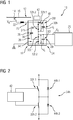
- FIG. 1 shows the implementation of the half-bridge circuit 34h of the high subunit 28h.
- This has two transistors, in particular each in the form of an IGBT (Insulated Gate Bipolar Transistor), which form the controllable switching elements 32h.1 and 32h.2.
- IGBT Insulated Gate Bipolar Transistor
- a diode 44h.1 or 44h.2 is connected in parallel to the switching elements.
- FIG Figure 1 The consumer 25 of the rail vehicle 10 that can be supplied with energy by the circuit 18 is shown in FIG Figure 1 shown schematically.
- this can be a traction system.
- this has a power supply unit which, based on the provided direct voltage V C , is used to generate an electrical current, in particular three-phase current, the properties of which are set in accordance with a traction power to be generated.
- the power supply unit can be designed as a traction converter.
- Figure 3 shows the design of the half-bridge circuit 34t of the deep subunit 28t with this design of the consumer 25 as a traction system. It is designed identically to the half-bridge circuit 34h and has two transistors, in particular each in the form of an IGBT (Insulated Gate Bipolar Transistor), which form the controllable switching elements 32t.1 and 32t.2. A diode 44t.1 or 44t.2 is connected in parallel to the switching elements.
- IGBT Insulated Gate Bipolar Transistor
- a consumer 25 that can be supplied by the circuit 18 can be an on-board electrical system supply. As is known, this has a converter at its input.
- An embodiment of the half-bridge circuit 34t of the deep subunit 28t adapted to this consumer 25 can - in contrast to the embodiment according to FIG Figure 3 - correspond to a simple series connection of two diodes.
- the Figures 4 to 6 each show an alternative embodiment of the circuit 18.
- the circuit 18, in particular the voltage conversion unit 26 has a means 46 which, with the element 38 of the charge transfer unit 36, defines a resonance frequency.
- the means 46 is in the embodiments according to FIG Figures 4 to 6 designed as one or more inductors.
- the control unit 42 is provided to control the switching unit 40, in particular its switching elements 32h.1 and 32h.2, with this resonance frequency. Thus, these switching elements can be switched with the lowest possible currents.
- the switching unit 40 is operated quasi-resonantly.
- the switching element 32h.1 is closed in particular in a currentless phase and opened again in the next currentless phase after a half-wave. A short subsequent delay time can have the effect that charges are removed from the switching elements. The same process then takes place for the switching element 32h.2.
- the means 46 is connected in series with the element 38 so that it is between the bridge circuits 34h and 34t, in particular are arranged between the bridge centers.
- the components of the circuit 18 have the following values: charge storage 30h and 30t each 500 ⁇ F; Element 38: 250 ⁇ F; Medium 46: 12 ⁇ H.
- Figure 5 shows an alternative embodiment with an embodiment of the means 46 with two elements 48 and 50, which in particular are each designed as an inductance. Both elements 48, 50 are connected to the terminals of the charge store 30t of the deep subunit 28t directly and in such a way that they are arranged between this charge store 30t and the consumer 25. The output terminals of these elements 48, 50 accordingly form the consumer side 24 of the circuit 18. The connection to the high subunit 28h is also branched off between the element 48 and the consumer 25.
- the training according to Figure 6 differs from the previous explanations in that the means 46 connects the high and low subunits 28h, 28t directly in series with one another.
- the circuit 18 in the embodiments according to FIGS Figures 1 and 4 to 6 a voltage conversion unit 26 which provides a voltage V C on the consumer side 24 which corresponds to half the mains voltage V N.
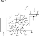
- Figure 7 shows the circuit 18 in a variant in which a voltage conversion unit 26 'is used to provide a voltage V C ' on the consumer side 24, which corresponds to twice the mains voltage V N '.
- this mains voltage V N ' is preferably 750V DC and the voltage V C ' provided by the voltage conversion unit 26 'is 1.5kV DC.
- the structure of the voltage conversion unit 26 ′ corresponds to that of the voltage conversion unit 26, with the input side 20 and the consumer side 24 being interchanged with one another compared to the above explanations.
- the reference symbols for the components of the Voltage conversion unit 26 ' are retained and the control of voltage conversion unit 26' takes place as in the above exemplary embodiments.
- the electrical current drawn from the mains supply 12 is fed into the circuit 18 at a point which is arranged between the subunits 28h and 28t.
- the potentials V h and V t of the subunits 28h, 28t are identical and each amount to the line voltage V N of 750V, ie half of the voltage V C provided on the consumer side 24.
- the principle of the invention has been explained in the drawings for an electrical phase.
- the circuit 18 can be constructed in multiple phases, in particular with a synchronous phase shift.
- the circuit is designed for 3 or 6-phase operation.
- a structurally simple design can be achieved with a design for 2-phase operation.
Landscapes
- Engineering & Computer Science (AREA)
- Power Engineering (AREA)
- Life Sciences & Earth Sciences (AREA)
- Sustainable Development (AREA)
- Sustainable Energy (AREA)
- Transportation (AREA)
- Mechanical Engineering (AREA)
- Electric Propulsion And Braking For Vehicles (AREA)
- Dc-Dc Converters (AREA)
- Rectifiers (AREA)
Priority Applications (1)
| Application Number | Priority Date | Filing Date | Title |
|---|---|---|---|
| PL15728469T PL3129254T3 (pl) | 2014-06-06 | 2015-06-03 | Pojazd szynowy zawierający obwód |
Applications Claiming Priority (2)
| Application Number | Priority Date | Filing Date | Title |
|---|---|---|---|
| DE102014210898.5A DE102014210898A1 (de) | 2014-06-06 | 2014-06-06 | Schaltung für ein Fahrzeug, insbesondere ein Schienenfahrzeug |
| PCT/EP2015/062321 WO2015185588A1 (de) | 2014-06-06 | 2015-06-03 | Schaltung für ein fahrzeug, insbesondere ein schienenfahrzeug |
Publications (2)
| Publication Number | Publication Date |
|---|---|
| EP3129254A1 EP3129254A1 (de) | 2017-02-15 |
| EP3129254B1 true EP3129254B1 (de) | 2021-07-28 |
Family
ID=53385613
Family Applications (1)
| Application Number | Title | Priority Date | Filing Date |
|---|---|---|---|
| EP15728469.6A Active EP3129254B1 (de) | 2014-06-06 | 2015-06-03 | Schienenfahrzeug umfassend eine schaltung |
Country Status (6)
| Country | Link |
|---|---|
| EP (1) | EP3129254B1 (pl) |
| DE (1) | DE102014210898A1 (pl) |
| ES (1) | ES2895624T3 (pl) |
| PL (1) | PL3129254T3 (pl) |
| RU (1) | RU2658225C2 (pl) |
| WO (1) | WO2015185588A1 (pl) |
Families Citing this family (1)
| Publication number | Priority date | Publication date | Assignee | Title |
|---|---|---|---|---|
| WO2022052074A1 (en) | 2020-09-14 | 2022-03-17 | Huawei Technologies Co., Ltd. | Dc/dc power converter, method for controlling switching thereof, dc/dc power converter arrangement and system |
Family Cites Families (13)
| Publication number | Priority date | Publication date | Assignee | Title |
|---|---|---|---|---|
| JPH05244766A (ja) * | 1992-02-27 | 1993-09-21 | Texas Instr Japan Ltd | チャージポンプ回路 |
| JPH09312968A (ja) * | 1996-05-22 | 1997-12-02 | Nec Corp | チャージポンプ回路 |
| RU2167071C1 (ru) * | 2000-09-21 | 2001-05-20 | Федеральное государственное унитарное предприятие "Центральный научно-исследовательский институт судовой электротехники и технологии" | Устройство преобразования электрической энергии |
| US7719343B2 (en) * | 2003-09-08 | 2010-05-18 | Peregrine Semiconductor Corporation | Low noise charge pump method and apparatus |
| EP1562279A3 (en) * | 2004-02-06 | 2005-11-02 | HONDA MOTOR CO., Ltd. | DC/DC converter and program |
| US7301400B1 (en) * | 2004-06-02 | 2007-11-27 | Rf Micro Devices, Inc. | Multi-phase switching power supply for mobile telephone applications |
| JP2007244078A (ja) * | 2006-03-07 | 2007-09-20 | Rohm Co Ltd | スイッチング電源装置およびその駆動回路、ならびにそれらを用いた電子機器 |
| CN101309048A (zh) * | 2007-05-17 | 2008-11-19 | 比亚迪股份有限公司 | 一种电荷泵装置及电源电路 |
| JP2010063267A (ja) * | 2008-09-03 | 2010-03-18 | Denso Corp | 電源装置 |
| WO2012074967A1 (en) * | 2010-11-29 | 2012-06-07 | President And Fellows Of Harvard College | Fully integrated 3-level dc/dc converter for nanosecond-scale dynamic voltage scaling with fast shunt regulation |
| US8680795B2 (en) * | 2011-06-03 | 2014-03-25 | Ford Global Technologies, Llc | Vehicle electric drive and power systems |
| US20140001856A1 (en) * | 2012-06-29 | 2014-01-02 | General Electric Company | Multilevel power converter |
| DE102012216691A1 (de) * | 2012-09-18 | 2014-03-20 | Bombardier Transportation Gmbh | Stromrichterschaltung und Verfahren zur Steuerung der Stromrichterschaltung |
-
2014
- 2014-06-06 DE DE102014210898.5A patent/DE102014210898A1/de not_active Ceased
-
2015
- 2015-06-03 ES ES15728469T patent/ES2895624T3/es active Active
- 2015-06-03 WO PCT/EP2015/062321 patent/WO2015185588A1/de not_active Ceased
- 2015-06-03 RU RU2016147714A patent/RU2658225C2/ru active
- 2015-06-03 PL PL15728469T patent/PL3129254T3/pl unknown
- 2015-06-03 EP EP15728469.6A patent/EP3129254B1/de active Active
Non-Patent Citations (1)
| Title |
|---|
| None * |
Also Published As
| Publication number | Publication date |
|---|---|
| WO2015185588A1 (de) | 2015-12-10 |
| EP3129254A1 (de) | 2017-02-15 |
| RU2658225C2 (ru) | 2018-06-19 |
| ES2895624T3 (es) | 2022-02-22 |
| RU2016147714A3 (pl) | 2018-06-06 |
| RU2016147714A (ru) | 2018-06-06 |
| DE102014210898A1 (de) | 2015-12-17 |
| PL3129254T3 (pl) | 2022-01-10 |
Similar Documents
| Publication | Publication Date | Title |
|---|---|---|
| EP3840980B1 (de) | Ladevorrichtung mit steuerbarer zwischenkreismittelpunktsspannung sowie antriebssystem mit einer derartigen ladevorrichtung | |
| DE102018216236B4 (de) | Ladeschaltung für einen fahrzeugseitigen elektrischen Energiespeicher | |
| DE102018221519B4 (de) | Fahrzeugseitige Ladevorrichtung | |
| EP2654190B1 (de) | Verfahren zum Betreiben einer elektrischen Schaltung | |
| DE102018207290B4 (de) | Konfigurierbare Ladevorrichtung und Verfahren zum Konfigurieren der Ladevorrichtung | |
| EP2623363B1 (de) | Vorrichtung und Verfahren zum Laden einer Traktionsbatterie eines Elektrofahrzeugs | |
| EP3123603B1 (de) | Modulationsverfahren für den hochsetzsteller-betrieb eines gegentaktwandlers | |
| EP2586646B1 (de) | Elektrische Energieversorgungsanordnung für Antriebseinrichtungen, zum Betreiben eines Schienenfahrzeugs an elektrischen Versorgungsnetzen | |
| DE102022209013B3 (de) | Kostenoptimierte Fahrzeugladeschaltung mit einphasiger Rückspeisefunktion | |
| DE102011079214B4 (de) | Umrichterschaltung mit zwei Umrichtern, die in Abhängigkeit von einem Zustand der Umrichterschaltung zwischen einer Parallelschaltung und einer Seriellschaltung umschaltbar sind | |
| DE102017115506A1 (de) | Steuervorrichtung für einen Inverter | |
| WO2020064429A1 (de) | Ladeschaltung für einen fahrzeugseitigen elektrischen energiespeicher | |
| EP2733837A1 (de) | Umrichter | |
| DE102016201283A1 (de) | Wechselrichter, elektrische Antriebsanordnung mit einem Wechselrichter | |
| EP3129254B1 (de) | Schienenfahrzeug umfassend eine schaltung | |
| DE102012206801A1 (de) | Schaltung mit einer stromrichterschaltung und verfahren zur leistungsanpassung | |
| DE102015105889A1 (de) | Schaltmodul und Umrichter mit wenigstens einem Schaltmodul | |
| DE102019215306B4 (de) | Zwischenkreisschaltung und fahrzeugseitige Ladeschaltung mit Zwischenkreisschaltung | |
| WO2019025399A1 (de) | Elektrische antriebsvorrichtung | |
| EP3373431A1 (de) | Einstellbarer energiewandler zur umwandlung von elektrischer energie in wärmeenergie | |
| EP3648328A1 (de) | Stromrichteranordnung für ein fahrzeug und fahrzeug mit einer solchen stromrichteranordnung | |
| DE102011081448A1 (de) | Schaltungsanordnung mit elektronischem Schalter und Induktivität | |
| DE102024205328A1 (de) | Schaltungsanordnung zur Energieversorgung von Gatetreibern, Mittelzweigvorrichtung für eine Inverterschaltung, Inverterschaltung und Verfahren zum Betrieb einer solchen, Vorrichtung zur Ansteuerung eines Stators einer elektrischen Maschine und elektrisches Antriebssystem | |
| DE102023201656A1 (de) | Ladevorrichtung sowie elektrisches Antriebs- und Ladesystem für ein Elektrofahrzeug | |
| EP4545348A1 (de) | Traktionsnetz für ein kraftfahrzeug |
Legal Events
| Date | Code | Title | Description |
|---|---|---|---|
| STAA | Information on the status of an ep patent application or granted ep patent |
Free format text: STATUS: THE INTERNATIONAL PUBLICATION HAS BEEN MADE |
|
| PUAI | Public reference made under article 153(3) epc to a published international application that has entered the european phase |
Free format text: ORIGINAL CODE: 0009012 |
|
| STAA | Information on the status of an ep patent application or granted ep patent |
Free format text: STATUS: REQUEST FOR EXAMINATION WAS MADE |
|
| 17P | Request for examination filed |
Effective date: 20161108 |
|
| AK | Designated contracting states |
Kind code of ref document: A1 Designated state(s): AL AT BE BG CH CY CZ DE DK EE ES FI FR GB GR HR HU IE IS IT LI LT LU LV MC MK MT NL NO PL PT RO RS SE SI SK SM TR |
|
| AX | Request for extension of the european patent |
Extension state: BA ME |
|
| RAP1 | Party data changed (applicant data changed or rights of an application transferred) |
Owner name: SIEMENS AKTIENGESELLSCHAFT |
|
| DAV | Request for validation of the european patent (deleted) | ||
| DAX | Request for extension of the european patent (deleted) | ||
| RAP1 | Party data changed (applicant data changed or rights of an application transferred) |
Owner name: SIEMENS MOBILITY GMBH |
|
| STAA | Information on the status of an ep patent application or granted ep patent |
Free format text: STATUS: EXAMINATION IS IN PROGRESS |
|
| 17Q | First examination report despatched |
Effective date: 20200305 |
|
| GRAP | Despatch of communication of intention to grant a patent |
Free format text: ORIGINAL CODE: EPIDOSNIGR1 |
|
| STAA | Information on the status of an ep patent application or granted ep patent |
Free format text: STATUS: GRANT OF PATENT IS INTENDED |
|
| INTG | Intention to grant announced |
Effective date: 20210210 |
|
| GRAS | Grant fee paid |
Free format text: ORIGINAL CODE: EPIDOSNIGR3 |
|
| GRAA | (expected) grant |
Free format text: ORIGINAL CODE: 0009210 |
|
| STAA | Information on the status of an ep patent application or granted ep patent |
Free format text: STATUS: THE PATENT HAS BEEN GRANTED |
|
| AK | Designated contracting states |
Kind code of ref document: B1 Designated state(s): AL AT BE BG CH CY CZ DE DK EE ES FI FR GB GR HR HU IE IS IT LI LT LU LV MC MK MT NL NO PL PT RO RS SE SI SK SM TR |
|
| REG | Reference to a national code |
Ref country code: GB Ref legal event code: FG4D Free format text: NOT ENGLISH |
|
| REG | Reference to a national code |
Ref country code: CH Ref legal event code: EP |
|
| REG | Reference to a national code |
Ref country code: AT Ref legal event code: REF Ref document number: 1414445 Country of ref document: AT Kind code of ref document: T Effective date: 20210815 |
|
| REG | Reference to a national code |
Ref country code: IE Ref legal event code: FG4D Free format text: LANGUAGE OF EP DOCUMENT: GERMAN |
|
| REG | Reference to a national code |
Ref country code: DE Ref legal event code: R096 Ref document number: 502015014998 Country of ref document: DE |
|
| REG | Reference to a national code |
Ref country code: LT Ref legal event code: MG9D |
|
| REG | Reference to a national code |
Ref country code: NL Ref legal event code: MP Effective date: 20210728 |
|
| PG25 | Lapsed in a contracting state [announced via postgrant information from national office to epo] |
Ref country code: BG Free format text: LAPSE BECAUSE OF FAILURE TO SUBMIT A TRANSLATION OF THE DESCRIPTION OR TO PAY THE FEE WITHIN THE PRESCRIBED TIME-LIMIT Effective date: 20211028 Ref country code: LT Free format text: LAPSE BECAUSE OF FAILURE TO SUBMIT A TRANSLATION OF THE DESCRIPTION OR TO PAY THE FEE WITHIN THE PRESCRIBED TIME-LIMIT Effective date: 20210728 Ref country code: NO Free format text: LAPSE BECAUSE OF FAILURE TO SUBMIT A TRANSLATION OF THE DESCRIPTION OR TO PAY THE FEE WITHIN THE PRESCRIBED TIME-LIMIT Effective date: 20211028 Ref country code: PT Free format text: LAPSE BECAUSE OF FAILURE TO SUBMIT A TRANSLATION OF THE DESCRIPTION OR TO PAY THE FEE WITHIN THE PRESCRIBED TIME-LIMIT Effective date: 20211129 Ref country code: NL Free format text: LAPSE BECAUSE OF FAILURE TO SUBMIT A TRANSLATION OF THE DESCRIPTION OR TO PAY THE FEE WITHIN THE PRESCRIBED TIME-LIMIT Effective date: 20210728 Ref country code: FI Free format text: LAPSE BECAUSE OF FAILURE TO SUBMIT A TRANSLATION OF THE DESCRIPTION OR TO PAY THE FEE WITHIN THE PRESCRIBED TIME-LIMIT Effective date: 20210728 Ref country code: SE Free format text: LAPSE BECAUSE OF FAILURE TO SUBMIT A TRANSLATION OF THE DESCRIPTION OR TO PAY THE FEE WITHIN THE PRESCRIBED TIME-LIMIT Effective date: 20210728 Ref country code: RS Free format text: LAPSE BECAUSE OF FAILURE TO SUBMIT A TRANSLATION OF THE DESCRIPTION OR TO PAY THE FEE WITHIN THE PRESCRIBED TIME-LIMIT Effective date: 20210728 Ref country code: HR Free format text: LAPSE BECAUSE OF FAILURE TO SUBMIT A TRANSLATION OF THE DESCRIPTION OR TO PAY THE FEE WITHIN THE PRESCRIBED TIME-LIMIT Effective date: 20210728 |
|
| REG | Reference to a national code |
Ref country code: ES Ref legal event code: FG2A Ref document number: 2895624 Country of ref document: ES Kind code of ref document: T3 Effective date: 20220222 |
|
| PG25 | Lapsed in a contracting state [announced via postgrant information from national office to epo] |
Ref country code: LV Free format text: LAPSE BECAUSE OF FAILURE TO SUBMIT A TRANSLATION OF THE DESCRIPTION OR TO PAY THE FEE WITHIN THE PRESCRIBED TIME-LIMIT Effective date: 20210728 Ref country code: GR Free format text: LAPSE BECAUSE OF FAILURE TO SUBMIT A TRANSLATION OF THE DESCRIPTION OR TO PAY THE FEE WITHIN THE PRESCRIBED TIME-LIMIT Effective date: 20211029 |
|
| PG25 | Lapsed in a contracting state [announced via postgrant information from national office to epo] |
Ref country code: DK Free format text: LAPSE BECAUSE OF FAILURE TO SUBMIT A TRANSLATION OF THE DESCRIPTION OR TO PAY THE FEE WITHIN THE PRESCRIBED TIME-LIMIT Effective date: 20210728 |
|
| REG | Reference to a national code |
Ref country code: DE Ref legal event code: R097 Ref document number: 502015014998 Country of ref document: DE |
|
| PG25 | Lapsed in a contracting state [announced via postgrant information from national office to epo] |
Ref country code: SM Free format text: LAPSE BECAUSE OF FAILURE TO SUBMIT A TRANSLATION OF THE DESCRIPTION OR TO PAY THE FEE WITHIN THE PRESCRIBED TIME-LIMIT Effective date: 20210728 Ref country code: SK Free format text: LAPSE BECAUSE OF FAILURE TO SUBMIT A TRANSLATION OF THE DESCRIPTION OR TO PAY THE FEE WITHIN THE PRESCRIBED TIME-LIMIT Effective date: 20210728 Ref country code: RO Free format text: LAPSE BECAUSE OF FAILURE TO SUBMIT A TRANSLATION OF THE DESCRIPTION OR TO PAY THE FEE WITHIN THE PRESCRIBED TIME-LIMIT Effective date: 20210728 Ref country code: EE Free format text: LAPSE BECAUSE OF FAILURE TO SUBMIT A TRANSLATION OF THE DESCRIPTION OR TO PAY THE FEE WITHIN THE PRESCRIBED TIME-LIMIT Effective date: 20210728 Ref country code: CZ Free format text: LAPSE BECAUSE OF FAILURE TO SUBMIT A TRANSLATION OF THE DESCRIPTION OR TO PAY THE FEE WITHIN THE PRESCRIBED TIME-LIMIT Effective date: 20210728 Ref country code: AL Free format text: LAPSE BECAUSE OF FAILURE TO SUBMIT A TRANSLATION OF THE DESCRIPTION OR TO PAY THE FEE WITHIN THE PRESCRIBED TIME-LIMIT Effective date: 20210728 |
|
| PLBE | No opposition filed within time limit |
Free format text: ORIGINAL CODE: 0009261 |
|
| STAA | Information on the status of an ep patent application or granted ep patent |
Free format text: STATUS: NO OPPOSITION FILED WITHIN TIME LIMIT |
|
| 26N | No opposition filed |
Effective date: 20220429 |
|
| PGFP | Annual fee paid to national office [announced via postgrant information from national office to epo] |
Ref country code: IT Payment date: 20220623 Year of fee payment: 8 |
|
| PGFP | Annual fee paid to national office [announced via postgrant information from national office to epo] |
Ref country code: PL Payment date: 20220527 Year of fee payment: 8 Ref country code: BE Payment date: 20220620 Year of fee payment: 8 |
|
| PGFP | Annual fee paid to national office [announced via postgrant information from national office to epo] |
Ref country code: ES Payment date: 20220920 Year of fee payment: 8 |
|
| PG25 | Lapsed in a contracting state [announced via postgrant information from national office to epo] |
Ref country code: MC Free format text: LAPSE BECAUSE OF FAILURE TO SUBMIT A TRANSLATION OF THE DESCRIPTION OR TO PAY THE FEE WITHIN THE PRESCRIBED TIME-LIMIT Effective date: 20210728 |
|
| REG | Reference to a national code |
Ref country code: CH Ref legal event code: PL |
|
| GBPC | Gb: european patent ceased through non-payment of renewal fee |
Effective date: 20220603 |
|
| PG25 | Lapsed in a contracting state [announced via postgrant information from national office to epo] |
Ref country code: LU Free format text: LAPSE BECAUSE OF NON-PAYMENT OF DUE FEES Effective date: 20220603 Ref country code: LI Free format text: LAPSE BECAUSE OF NON-PAYMENT OF DUE FEES Effective date: 20220630 Ref country code: IE Free format text: LAPSE BECAUSE OF NON-PAYMENT OF DUE FEES Effective date: 20220603 Ref country code: FR Free format text: LAPSE BECAUSE OF NON-PAYMENT OF DUE FEES Effective date: 20220630 Ref country code: CH Free format text: LAPSE BECAUSE OF NON-PAYMENT OF DUE FEES Effective date: 20220630 |
|
| PG25 | Lapsed in a contracting state [announced via postgrant information from national office to epo] |
Ref country code: GB Free format text: LAPSE BECAUSE OF NON-PAYMENT OF DUE FEES Effective date: 20220603 |
|
| PGFP | Annual fee paid to national office [announced via postgrant information from national office to epo] |
Ref country code: DE Payment date: 20220630 Year of fee payment: 9 |
|
| REG | Reference to a national code |
Ref country code: AT Ref legal event code: MM01 Ref document number: 1414445 Country of ref document: AT Kind code of ref document: T Effective date: 20220603 |
|
| PG25 | Lapsed in a contracting state [announced via postgrant information from national office to epo] |
Ref country code: AT Free format text: LAPSE BECAUSE OF NON-PAYMENT OF DUE FEES Effective date: 20220603 |
|
| REG | Reference to a national code |
Ref country code: BE Ref legal event code: MM Effective date: 20230630 |
|
| PG25 | Lapsed in a contracting state [announced via postgrant information from national office to epo] |
Ref country code: HU Free format text: LAPSE BECAUSE OF FAILURE TO SUBMIT A TRANSLATION OF THE DESCRIPTION OR TO PAY THE FEE WITHIN THE PRESCRIBED TIME-LIMIT; INVALID AB INITIO Effective date: 20150603 |
|
| PG25 | Lapsed in a contracting state [announced via postgrant information from national office to epo] |
Ref country code: MK Free format text: LAPSE BECAUSE OF FAILURE TO SUBMIT A TRANSLATION OF THE DESCRIPTION OR TO PAY THE FEE WITHIN THE PRESCRIBED TIME-LIMIT Effective date: 20210728 Ref country code: CY Free format text: LAPSE BECAUSE OF FAILURE TO SUBMIT A TRANSLATION OF THE DESCRIPTION OR TO PAY THE FEE WITHIN THE PRESCRIBED TIME-LIMIT Effective date: 20210728 |
|
| PG25 | Lapsed in a contracting state [announced via postgrant information from national office to epo] |
Ref country code: BE Free format text: LAPSE BECAUSE OF NON-PAYMENT OF DUE FEES Effective date: 20230630 |
|
| REG | Reference to a national code |
Ref country code: ES Ref legal event code: FD2A Effective date: 20240729 |
|
| PG25 | Lapsed in a contracting state [announced via postgrant information from national office to epo] |
Ref country code: IT Free format text: LAPSE BECAUSE OF NON-PAYMENT OF DUE FEES Effective date: 20230603 |
|
| PG25 | Lapsed in a contracting state [announced via postgrant information from national office to epo] |
Ref country code: MT Free format text: LAPSE BECAUSE OF FAILURE TO SUBMIT A TRANSLATION OF THE DESCRIPTION OR TO PAY THE FEE WITHIN THE PRESCRIBED TIME-LIMIT Effective date: 20210728 |
|
| PG25 | Lapsed in a contracting state [announced via postgrant information from national office to epo] |
Ref country code: ES Free format text: LAPSE BECAUSE OF NON-PAYMENT OF DUE FEES Effective date: 20230604 |
|
| PG25 | Lapsed in a contracting state [announced via postgrant information from national office to epo] |
Ref country code: ES Free format text: LAPSE BECAUSE OF NON-PAYMENT OF DUE FEES Effective date: 20230604 |
|
| REG | Reference to a national code |
Ref country code: DE Ref legal event code: R119 Ref document number: 502015014998 Country of ref document: DE |
|
| PG25 | Lapsed in a contracting state [announced via postgrant information from national office to epo] |
Ref country code: PL Free format text: LAPSE BECAUSE OF NON-PAYMENT OF DUE FEES Effective date: 20230603 |
|
| PG25 | Lapsed in a contracting state [announced via postgrant information from national office to epo] |
Ref country code: PL Free format text: LAPSE BECAUSE OF NON-PAYMENT OF DUE FEES Effective date: 20230603 |
|
| PG25 | Lapsed in a contracting state [announced via postgrant information from national office to epo] |
Ref country code: DE Free format text: LAPSE BECAUSE OF NON-PAYMENT OF DUE FEES Effective date: 20250101 |
|
| PG25 | Lapsed in a contracting state [announced via postgrant information from national office to epo] |
Ref country code: TR Free format text: LAPSE BECAUSE OF FAILURE TO SUBMIT A TRANSLATION OF THE DESCRIPTION OR TO PAY THE FEE WITHIN THE PRESCRIBED TIME-LIMIT Effective date: 20210728 |