EP3128643A1 - System for wirelessly supplying power during moving - Google Patents
System for wirelessly supplying power during moving Download PDFInfo
- Publication number
- EP3128643A1 EP3128643A1 EP14884347.7A EP14884347A EP3128643A1 EP 3128643 A1 EP3128643 A1 EP 3128643A1 EP 14884347 A EP14884347 A EP 14884347A EP 3128643 A1 EP3128643 A1 EP 3128643A1
- Authority
- EP
- European Patent Office
- Prior art keywords
- power supply
- primary
- transformers
- primary power
- series
- Prior art date
- Legal status (The legal status is an assumption and is not a legal conclusion. Google has not performed a legal analysis and makes no representation as to the accuracy of the status listed.)
- Withdrawn
Links
Images


Classifications
-
- B—PERFORMING OPERATIONS; TRANSPORTING
- B60—VEHICLES IN GENERAL
- B60L—PROPULSION OF ELECTRICALLY-PROPELLED VEHICLES; SUPPLYING ELECTRIC POWER FOR AUXILIARY EQUIPMENT OF ELECTRICALLY-PROPELLED VEHICLES; ELECTRODYNAMIC BRAKE SYSTEMS FOR VEHICLES IN GENERAL; MAGNETIC SUSPENSION OR LEVITATION FOR VEHICLES; MONITORING OPERATING VARIABLES OF ELECTRICALLY-PROPELLED VEHICLES; ELECTRIC SAFETY DEVICES FOR ELECTRICALLY-PROPELLED VEHICLES
- B60L5/00—Current collectors for power supply lines of electrically-propelled vehicles
- B60L5/005—Current collectors for power supply lines of electrically-propelled vehicles without mechanical contact between the collector and the power supply line
-
- B—PERFORMING OPERATIONS; TRANSPORTING
- B60—VEHICLES IN GENERAL
- B60L—PROPULSION OF ELECTRICALLY-PROPELLED VEHICLES; SUPPLYING ELECTRIC POWER FOR AUXILIARY EQUIPMENT OF ELECTRICALLY-PROPELLED VEHICLES; ELECTRODYNAMIC BRAKE SYSTEMS FOR VEHICLES IN GENERAL; MAGNETIC SUSPENSION OR LEVITATION FOR VEHICLES; MONITORING OPERATING VARIABLES OF ELECTRICALLY-PROPELLED VEHICLES; ELECTRIC SAFETY DEVICES FOR ELECTRICALLY-PROPELLED VEHICLES
- B60L53/00—Methods of charging batteries, specially adapted for electric vehicles; Charging stations or on-board charging equipment therefor; Exchange of energy storage elements in electric vehicles
- B60L53/10—Methods of charging batteries, specially adapted for electric vehicles; Charging stations or on-board charging equipment therefor; Exchange of energy storage elements in electric vehicles characterised by the energy transfer between the charging station and the vehicle
- B60L53/12—Inductive energy transfer
- B60L53/122—Circuits or methods for driving the primary coil, e.g. supplying electric power to the coil
-
- B—PERFORMING OPERATIONS; TRANSPORTING
- B60—VEHICLES IN GENERAL
- B60L—PROPULSION OF ELECTRICALLY-PROPELLED VEHICLES; SUPPLYING ELECTRIC POWER FOR AUXILIARY EQUIPMENT OF ELECTRICALLY-PROPELLED VEHICLES; ELECTRODYNAMIC BRAKE SYSTEMS FOR VEHICLES IN GENERAL; MAGNETIC SUSPENSION OR LEVITATION FOR VEHICLES; MONITORING OPERATING VARIABLES OF ELECTRICALLY-PROPELLED VEHICLES; ELECTRIC SAFETY DEVICES FOR ELECTRICALLY-PROPELLED VEHICLES
- B60L53/00—Methods of charging batteries, specially adapted for electric vehicles; Charging stations or on-board charging equipment therefor; Exchange of energy storage elements in electric vehicles
- B60L53/20—Methods of charging batteries, specially adapted for electric vehicles; Charging stations or on-board charging equipment therefor; Exchange of energy storage elements in electric vehicles characterised by converters located in the vehicle
-
- B—PERFORMING OPERATIONS; TRANSPORTING
- B60—VEHICLES IN GENERAL
- B60M—POWER SUPPLY LINES, AND DEVICES ALONG RAILS, FOR ELECTRICALLY- PROPELLED VEHICLES
- B60M7/00—Power lines or rails specially adapted for electrically-propelled vehicles of special types, e.g. suspension tramway, ropeway, underground railway
- B60M7/003—Power lines or rails specially adapted for electrically-propelled vehicles of special types, e.g. suspension tramway, ropeway, underground railway for vehicles using stored power (e.g. charging stations)
-
- H—ELECTRICITY
- H02—GENERATION; CONVERSION OR DISTRIBUTION OF ELECTRIC POWER
- H02J—CIRCUIT ARRANGEMENTS OR SYSTEMS FOR SUPPLYING OR DISTRIBUTING ELECTRIC POWER; SYSTEMS FOR STORING ELECTRIC ENERGY
- H02J50/00—Circuit arrangements or systems for wireless supply or distribution of electric power
- H02J50/10—Circuit arrangements or systems for wireless supply or distribution of electric power using inductive coupling
- H02J50/12—Circuit arrangements or systems for wireless supply or distribution of electric power using inductive coupling of the resonant type
-
- H—ELECTRICITY
- H02—GENERATION; CONVERSION OR DISTRIBUTION OF ELECTRIC POWER
- H02J—CIRCUIT ARRANGEMENTS OR SYSTEMS FOR SUPPLYING OR DISTRIBUTING ELECTRIC POWER; SYSTEMS FOR STORING ELECTRIC ENERGY
- H02J50/00—Circuit arrangements or systems for wireless supply or distribution of electric power
- H02J50/40—Circuit arrangements or systems for wireless supply or distribution of electric power using two or more transmitting or receiving devices
-
- B—PERFORMING OPERATIONS; TRANSPORTING
- B60—VEHICLES IN GENERAL
- B60L—PROPULSION OF ELECTRICALLY-PROPELLED VEHICLES; SUPPLYING ELECTRIC POWER FOR AUXILIARY EQUIPMENT OF ELECTRICALLY-PROPELLED VEHICLES; ELECTRODYNAMIC BRAKE SYSTEMS FOR VEHICLES IN GENERAL; MAGNETIC SUSPENSION OR LEVITATION FOR VEHICLES; MONITORING OPERATING VARIABLES OF ELECTRICALLY-PROPELLED VEHICLES; ELECTRIC SAFETY DEVICES FOR ELECTRICALLY-PROPELLED VEHICLES
- B60L2210/00—Converter types
- B60L2210/30—AC to DC converters
-
- H—ELECTRICITY
- H02—GENERATION; CONVERSION OR DISTRIBUTION OF ELECTRIC POWER
- H02J—CIRCUIT ARRANGEMENTS OR SYSTEMS FOR SUPPLYING OR DISTRIBUTING ELECTRIC POWER; SYSTEMS FOR STORING ELECTRIC ENERGY
- H02J50/00—Circuit arrangements or systems for wireless supply or distribution of electric power
- H02J50/70—Circuit arrangements or systems for wireless supply or distribution of electric power involving the reduction of electric, magnetic or electromagnetic leakage fields
-
- H—ELECTRICITY
- H02—GENERATION; CONVERSION OR DISTRIBUTION OF ELECTRIC POWER
- H02J—CIRCUIT ARRANGEMENTS OR SYSTEMS FOR SUPPLYING OR DISTRIBUTING ELECTRIC POWER; SYSTEMS FOR STORING ELECTRIC ENERGY
- H02J50/00—Circuit arrangements or systems for wireless supply or distribution of electric power
- H02J50/90—Circuit arrangements or systems for wireless supply or distribution of electric power involving detection or optimisation of position, e.g. alignment
-
- Y—GENERAL TAGGING OF NEW TECHNOLOGICAL DEVELOPMENTS; GENERAL TAGGING OF CROSS-SECTIONAL TECHNOLOGIES SPANNING OVER SEVERAL SECTIONS OF THE IPC; TECHNICAL SUBJECTS COVERED BY FORMER USPC CROSS-REFERENCE ART COLLECTIONS [XRACs] AND DIGESTS
- Y02—TECHNOLOGIES OR APPLICATIONS FOR MITIGATION OR ADAPTATION AGAINST CLIMATE CHANGE
- Y02T—CLIMATE CHANGE MITIGATION TECHNOLOGIES RELATED TO TRANSPORTATION
- Y02T10/00—Road transport of goods or passengers
- Y02T10/60—Other road transportation technologies with climate change mitigation effect
- Y02T10/70—Energy storage systems for electromobility, e.g. batteries
-
- Y—GENERAL TAGGING OF NEW TECHNOLOGICAL DEVELOPMENTS; GENERAL TAGGING OF CROSS-SECTIONAL TECHNOLOGIES SPANNING OVER SEVERAL SECTIONS OF THE IPC; TECHNICAL SUBJECTS COVERED BY FORMER USPC CROSS-REFERENCE ART COLLECTIONS [XRACs] AND DIGESTS
- Y02—TECHNOLOGIES OR APPLICATIONS FOR MITIGATION OR ADAPTATION AGAINST CLIMATE CHANGE
- Y02T—CLIMATE CHANGE MITIGATION TECHNOLOGIES RELATED TO TRANSPORTATION
- Y02T10/00—Road transport of goods or passengers
- Y02T10/60—Other road transportation technologies with climate change mitigation effect
- Y02T10/7072—Electromobility specific charging systems or methods for batteries, ultracapacitors, supercapacitors or double-layer capacitors
-
- Y—GENERAL TAGGING OF NEW TECHNOLOGICAL DEVELOPMENTS; GENERAL TAGGING OF CROSS-SECTIONAL TECHNOLOGIES SPANNING OVER SEVERAL SECTIONS OF THE IPC; TECHNICAL SUBJECTS COVERED BY FORMER USPC CROSS-REFERENCE ART COLLECTIONS [XRACs] AND DIGESTS
- Y02—TECHNOLOGIES OR APPLICATIONS FOR MITIGATION OR ADAPTATION AGAINST CLIMATE CHANGE
- Y02T—CLIMATE CHANGE MITIGATION TECHNOLOGIES RELATED TO TRANSPORTATION
- Y02T90/00—Enabling technologies or technologies with a potential or indirect contribution to GHG emissions mitigation
- Y02T90/10—Technologies relating to charging of electric vehicles
- Y02T90/12—Electric charging stations
-
- Y—GENERAL TAGGING OF NEW TECHNOLOGICAL DEVELOPMENTS; GENERAL TAGGING OF CROSS-SECTIONAL TECHNOLOGIES SPANNING OVER SEVERAL SECTIONS OF THE IPC; TECHNICAL SUBJECTS COVERED BY FORMER USPC CROSS-REFERENCE ART COLLECTIONS [XRACs] AND DIGESTS
- Y02—TECHNOLOGIES OR APPLICATIONS FOR MITIGATION OR ADAPTATION AGAINST CLIMATE CHANGE
- Y02T—CLIMATE CHANGE MITIGATION TECHNOLOGIES RELATED TO TRANSPORTATION
- Y02T90/00—Enabling technologies or technologies with a potential or indirect contribution to GHG emissions mitigation
- Y02T90/10—Technologies relating to charging of electric vehicles
- Y02T90/14—Plug-in electric vehicles
Definitions
- the present invention relates to a power supply system for contactless power supply to a running mobile structure.
- contactless power supply systems for charging the batteries of electric automobiles or plug-in hybrid cars have been developed.
- one of such systems includes a secondary coil (receiver coil) 102 of a contactless power supply transformer mounted on a vehicle floor and a primary coil (transmitter coil) 202 provided on the ground which oppose each other to supply power from the ground to a stopping vehicle in contactless manner, as shown in FIG. 13 .
- the following patent document 1 discloses the use of a double-sided coil formed of a plate-like ferrite core 10 around which a wire 11 is wound, as shown in FIG. 14 , aiming for raising a tolerance for misalignments or gap variations between a primary coil and a secondary coil of the charging system and downsizing the coils.
- a primary magnetic flux passes through the ferrite core 10, entering and exiting into/from magnetic poles at both ends.
- the following patent document 2 discloses a coil including a H-shaped ferrite core, as shown in FIG. 15 , which has been developed for further reducing the size and weight of the double-sided coil.
- a wire 11 is wound around the portion of the H-shaped core corresponding to a transverse bar while the parallel portions of the H-shaped core at both sides work as magnetic poles.
- the patent document 2 further discloses that the tolerance for misalignments is set to be larger along the line (x-direction) parallel to both magnetic poles than along the line (y-direction) orthogonal to the magnetic poles.
- the following patent document 3 discloses a system in which multiple power supply devices each including an AC source, a high-frequency power driver, a primary coil, a primary self-resonance coil, a power sensor, and an ECU are installed on a driving route to supply power to running vehicles having receiver coils.
- the following nonpatent literature 1 has studied the characteristics of multiple resonators represented by the equivalent circuit in FIG. 16 , which are placed following the source coil of a power supply device as shown in FIG. 17 , aiming for elongating the power supply intervals of individual power supply devices.
- Nonpatent Literature 1 Jin Wook Kim et al., "Wireless power transfer for free positioning using compact planar multiple self-resonators" 2012 IEEE MTT-S International IMWS-IWPT 2012 pp.127-130
- the nonpatent literature 1 reports that as shown in FIG. 18 , "dead zones" in which the power supply to secondary coils is interrupted still appear on the primary coils even when closely arranged with no gap as shown in FIG. 17 .
- the present invention has been made in view of such situations. It is an object of the present invention to provide a contactless power supply system of which a primary side (on the ground) can be installed by simple work and which can ensure longer power supply intervals.
- a contactless power supply system for supplying power to a running mobile structure from ground in contactless manner, the system comprises: on the ground, a plurality of primary power supply transformers installed on a driving route of the mobile structure; a high-frequency power source which supplies a high-frequency alternating current to the primary power supply transformers via a cable; and a primary series capacitor connected in series to the primary power supply transformers; on the mobile structure, a secondary power supply transformer supplied with power from the primary power supply transformers in contactless manner; a rectifier which rectifies an alternating current received by the secondary power supply transformer for charging; and a secondary resonance capacitor connected in series or in parallel between the secondary power supply transformer and the rectifier, wherein the primary power supply transformers and the secondary power supply transformer each include a double-sided coil having a core with magnetic poles at both ends and a portion between the magnetic poles around which a wire is wound, and the primary power supply transformers and the secondary power supply transformer are installed on the driving route or on the mobile structure such that a direction of
- the primary power supply transformers disposed on the driving route are made of double-sided coils having a larger misalignment tolerance and they are aligned in the direction (along the line parallel to the magnetic poles at both ends of the core) of the double-sided coils with the larger misalignment tolerance. Because of this, no interruption of the power supply from the primary power supply transformers to the secondary coil occurs even if the primary power supply transformers are arranged in a stepping stone-like form.
- the primary power supply transformers can be connected in series to the high-frequency power source.
- the primary power supply transformers connected in series are more easily wired and installed on the driving route by a simple work.
- the primary series capacitor can be connected in series only between the high-frequency power source and one of the primary power supply transformers connected to the high-frequency power source.
- the value of capacitance of the primary series capacitor is set such that the primary-side circuit forms a series resonance circuit. Meanwhile, when the secondary resonance capacitor is connected in parallel, the value of capacitance is set such that the primary-side power factor becomes equal to 1.
- the primary series capacitor can be divided and connected in series between the high-frequency power source and one of the primary power supply transformers connected to the high-frequency power source and between the neighboring primary power supply transformers, respectively.
- the value of capacitance of each divided primary series capacitor is set to n ⁇ C1 where n represents the number of the divided primary series capacitors.
- the value of capacitance of C1 is set such that the primary-side circuit forms a resonance circuit.
- the value of capacitance of C1 is set such that the primary-side power factor becomes equal to 1.
- the primary power supply transformers can be also connected in parallel to the high-frequency power source.
- the single primary series capacitor is connected between the high-frequency power source and each of the primary power supply transformers connected in parallel to the high-frequency power source.
- the value of capacitance of the primary series capacitor is set such that the primary-side circuit forms a series resonance circuit. Meanwhile, when the secondary resonance capacitor is connected in parallel, the value of capacitance is set such that the primary-side power factor becomes equal to 1.
- the core of the double-sided coil is preferably an H-shaped core.
- the use of the H-shaped core can contribute to decreasing the size and weight of the primary power supply transformers.
- the primary power supply transformers can be disposed in a stepping stone-like form, therefore, can be installed on driving routes by a simple work. Also, a less number of primary power supply transformers can ensure longer power supply intervals.
- FIG. 1 shows a contactless power supply system according to one embodiment of the present invention.
- FIG. 1(a) is a side view of primary power supply transformers 1, 2, 3, and 4 provided separately on a driving route on the ground and a secondary power supply transformer 20 mounted on a vehicle.
- the reference numeral 21 indicates the secondary power supply transformer 20 when moved.
- FIG. 1(b) is a plan view of the same.
- the primary power supply transformers 1, 2, 3, and 4 and the secondary power supply transformer 20 each include a double-sided coil having an H-shaped core around of which a wire 33 is wound around a portion between magnetic poles 31 and 32, and an aluminum shield plate 34 for shielding from a leakage of magnetic flux which occurs on the sides of the double-sided coil opposite to the faces opposing the other coil.
- the primary power supply transformers 1, 2, 3, and 4 are provided on the driving route so that the direction (x-direction in FIG. 15 ) of a line parallel to the magnetic poles 31 and 32 matches a vehicle traveling direction on the driving route.
- the secondary power supply transformer 20 is mounted on the vehicle so that the same direction matches a vehicle front-back direction.
- the primary power supply transformers are also separately provided along the driving route with a spacing which is set not to exceed a distance 3D between the centers of the magnetic poles of the neighboring primary power supply transformers where D represents the length of the magnetic poles (that is, the spacing I from the end of the magnetic pole of one primary power supply transformer to that of another primary power supply transformer is set not to exceed 2D).
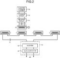
- FIG. 2 shows one example of the circuit configuration of the contactless power supply system.
- the system includes, on the ground, a high-frequency power source 40 to supply a high-frequency alternating current to the primary power supply transformers 1, 2, 3, and 4 and a primary series capacitor C1 connected in series to the primary power supply transformers 1, 2, 3, and 4.
- the primary power supply transformers 1, 2, 3, and 4 are connected in series to the high-frequency power source 40.
- the high-frequency power source 40 includes an AC/DC converter 41 to convert the alternating current for commercial power into a direct current and an inverter 42 to generate a high-frequency alternating current from the converted direct current.
- the system includes, on the vehicle, a rectifier circuit 51 to rectify the alternating current received by the secondary power supply transformer 20, a charger circuit 52 to charge an electric storage element 53 with the rectified current, and a secondary resonance capacitor C2 connected in parallel between the secondary power supply transformer 20 and the rectifier circuit 51.
- the capacitance of the secondary resonance capacitor C2 is defined by the expression (1) so as to form a parallel resonance circuit on the secondary side.
- the capacitance of the primary series capacitor C1 is defined by the expression (2) so as to set the primary-side power factor to 1.
- C 1 1 ⁇ 2 a 2 l o l 2 L 2 + l 1
- 10 exciting inductance
- 11 exciting inductance
- 12 exciting inductance.
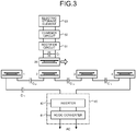
- the primary series capacitor C1 can be divided into C11, C12, C13, and C14 to connect in series between the high-frequency power source 40 and the primary power supply transformer 1, between the primary power supply transformer 1 and the primary power supply transformer 2, between the primary power supply transformer 2 and the primary power supply transformer 3, and between the primary power supply transformer 3 and the primary power supply transformer 4, respectively.
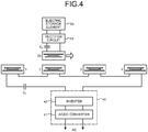
- FIG. 4 shows a circuit in which the secondary resonance capacitor C2 of the vehicle is connected in series between the secondary power supply transformer 20 and the rectifier circuit 51.
- the capacitance of the secondary resonance capacitor C2 is defined by the expression (1) so as to form a series resonance circuit on the secondary side.
- the primary series capacitor C1 is defined by the expression (3) so as to form a series resonance circuit on the primary side.
- C 1 1 ⁇ 2 L 1 where L1: primary-side self-inductance.
- the primary series capacitor C1 in FIG. 4 can be divided into C11, C12, C13, and C14 to connect in series between the high-frequency power source 40 and the primary power supply transformer 1, between the primary power supply transformer 1 and the primary power supply transformer 2, between the primary power supply transformer 2 and the primary power supply transformer 3, and between the primary power supply transformer 3 and the primary power supply transformer 4, respectively, as shown in FIG. 5 .
- the primary power supply transformers 1, 2, 3, and 4 can be connected in parallel to the high-frequency power source 40.
- the single primary series capacitor C1 is connected in series between the high-frequency power source 40 and each of the primary power supply transformers 1, 2, 3, and 4.
- the capacitance of the primary series capacitor C1 is defined by the expression (2) so as to set the primary-side power factor to 1, when the secondary resonance capacitor C2 is connected in parallel between the secondary power supply transformer 20 and the rectifier circuit 51, as shown in FIG. 6 .
- the capacitance of the primary series capacitor C1 is defined by the expression (3) so as to form a series resonance circuit on the primary side.
- FIG. 9 shows an actual apparatus used for the test.
- the primary power supply transformers and the secondary power supply transformer each include a double-sided coil having an H-shaped core around which a wire is wound, with magnetic poles in length of 300 mm and distanced by 250 mm. They are arranged in the same orientation as in FIG. 1 .
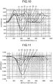
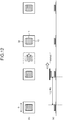
- FIG. 10 shows variations in the output of the secondary power supply transformer when the spacing between two primary power supply transformers was changed. The variations were measured under the condition that DC input is 210V, output frequency f of a high-frequency power source is 30khz, gap between the primary power supply transformers and the secondary power supply transformer is 70 mm.
- the abscissa axis indicates the moved position of the secondary power supply transformer while the vertical axis indicates the output power (W) from the secondary power supply transformer.
- the curve (1) represents a result when the distance between the ends of the magnetic poles of the two primary power supply transformers (hereinafter, referred to as transformer spacing) was set to 300 mm
- the curve (2) represents a result when the transformer spacing was set to 350 mm
- the curve (3) represents a result when the transformer spacing was set to 400 mm
- the curve (4) represents a result when the transformer spacing was set to 450 mm
- the curve (5) represents a result when the transformer spacing was set to 500 mm
- the curve (6) represents a result when the transformer spacing was set to 550 mm
- the curve (7) represents a result when the transformer spacing was set to 600 mm.
- FIG. 11 shows the power supply efficiency (ratio of input power to the primary power supply transformers and output power from the secondary power supply transformer) of FIG. 10 .
- the results of the measurement can confirm that even with the transformer spacing of 600 mm (that is, twice the length of the magnetic poles of the primary power supply transformer), the power supply to the secondary power supply transformer is feasible.
- the "transformer spacing as twice the length of the magnetic poles of the primary power supply transformer” signifies that the distance from the center of the magnetic poles of one primary power supply transformer to the centers of the magnetic poles of the neighboring primary power supply transformers is three times longer than the length of the magnetic poles.
- the contactless power supply system of the present invention can continuously supply power from the primary power supply transformers separated in a stepping stone-like form to the secondary power supply transformer unless the distance from the center of the magnetic poles of one primary power supply transformer to the centers of the magnetic poles of the neighboring primary power supply transformers exceeds 3D where D represents the size of the magnetic poles of the primary power supply transformers.
- a double-sided coil having the plate-like core 10 around which the wire 11 is wound, as shown in FIG. 12 can be used.
- the contactless power supply system according to the present invention can be installed on the driving route of a mobile structure by simple work, can supply power to a running mobile structure over a longer interval, and are widely usable to supply power to running mobile structures of various types including an electric automobile or a plug-in hybrid car.
Landscapes
- Engineering & Computer Science (AREA)
- Power Engineering (AREA)
- Mechanical Engineering (AREA)
- Transportation (AREA)
- Computer Networks & Wireless Communication (AREA)
- Current-Collector Devices For Electrically Propelled Vehicles (AREA)
- Electric Propulsion And Braking For Vehicles (AREA)
Abstract
Description
- The present invention relates to a power supply system for contactless power supply to a running mobile structure.
- Conventionally, contactless power supply systems for charging the batteries of electric automobiles or plug-in hybrid cars have been developed. one of such systems includes a secondary coil (receiver coil) 102 of a contactless power supply transformer mounted on a vehicle floor and a primary coil (transmitter coil) 202 provided on the ground which oppose each other to supply power from the ground to a stopping vehicle in contactless manner, as shown in
FIG. 13 . - The following
patent document 1 discloses the use of a double-sided coil formed of a plate-like ferrite core 10 around which awire 11 is wound, as shown inFIG. 14 , aiming for raising a tolerance for misalignments or gap variations between a primary coil and a secondary coil of the charging system and downsizing the coils. In this double-sided coil, a primary magnetic flux passes through theferrite core 10, entering and exiting into/from magnetic poles at both ends. - The following
patent document 2 discloses a coil including a H-shaped ferrite core, as shown inFIG. 15 , which has been developed for further reducing the size and weight of the double-sided coil. In this coil awire 11 is wound around the portion of the H-shaped core corresponding to a transverse bar while the parallel portions of the H-shaped core at both sides work as magnetic poles. - The
patent document 2 further discloses that the tolerance for misalignments is set to be larger along the line (x-direction) parallel to both magnetic poles than along the line (y-direction) orthogonal to the magnetic poles. - Currently, electric automobiles face a problem in a relatively short driving range per charging because of a battery performance. In view of solving the problem, various kinds of contactless power supply systems for running vehicles have been devised.
- The following
patent document 3 discloses a system in which multiple power supply devices each including an AC source, a high-frequency power driver, a primary coil, a primary self-resonance coil, a power sensor, and an ECU are installed on a driving route to supply power to running vehicles having receiver coils. - The following
nonpatent literature 1 has studied the characteristics of multiple resonators represented by the equivalent circuit inFIG. 16 , which are placed following the source coil of a power supply device as shown inFIG. 17 , aiming for elongating the power supply intervals of individual power supply devices. -
- Patent Literature 1: Japanese Patent Laid-open Publication No.
2010-172084 - Patent Literature 2: Japanese Patent Laid-open Publication No.
2012-175793 - Patent Literature 3: Japanese Patent Laid-open Publication No.
2011-166992 - Nonpatent Literature 1: Jin Wook Kim et al., "Wireless power transfer for free positioning using compact planar multiple self-resonators" 2012 IEEE MTT-S International IMWS-IWPT 2012 pp.127-130
- The
nonpatent literature 1 reports that as shown inFIG. 18 , "dead zones" in which the power supply to secondary coils is interrupted still appear on the primary coils even when closely arranged with no gap as shown inFIG. 17 . - The present invention has been made in view of such situations. It is an object of the present invention to provide a contactless power supply system of which a primary side (on the ground) can be installed by simple work and which can ensure longer power supply intervals.
- According to the present invention, a contactless power supply system for supplying power to a running mobile structure from ground in contactless manner, the system comprises: on the ground, a plurality of primary power supply transformers installed on a driving route of the mobile structure; a high-frequency power source which supplies a high-frequency alternating current to the primary power supply transformers via a cable; and
a primary series capacitor connected in series to the primary power supply transformers; on the mobile structure,
a secondary power supply transformer supplied with power from the primary power supply transformers in contactless manner; a rectifier which rectifies an alternating current received by the secondary power supply transformer for charging; and a secondary resonance capacitor connected in series or in parallel between the secondary power supply transformer and the rectifier, wherein the primary power supply transformers and the secondary power supply transformer each include a double-sided coil having a core with magnetic poles at both ends and a portion between the magnetic poles around which a wire is wound, and the primary power supply transformers and the secondary power supply transformer are installed on the driving route or on the mobile structure such that a direction of a line parallel to the magnetic poles at both ends of the core matches a traveling direction of the mobile structure; and the primary power supply transformers are separately installed with a spacing along the driving route, the spacing being set such that a distance from a center of the magnetic poles of the primary power supply transformer to a center of the magnetic poles of a neighboring primary power supply transformer does not exceed 3D where D represents a size of the magnetic poles of the primary power supply transformers in the traveling direction. - In such a system the primary power supply transformers disposed on the driving route are made of double-sided coils having a larger misalignment tolerance and they are aligned in the direction (along the line parallel to the magnetic poles at both ends of the core) of the double-sided coils with the larger misalignment tolerance. Because of this, no interruption of the power supply from the primary power supply transformers to the secondary coil occurs even if the primary power supply transformers are arranged in a stepping stone-like form.
- Further, in the contactless power supply system of the present invention, the primary power supply transformers can be connected in series to the high-frequency power source.
- The primary power supply transformers connected in series are more easily wired and installed on the driving route by a simple work.
- In this case, the primary series capacitor can be connected in series only between the high-frequency power source and one of the primary power supply transformers connected to the high-frequency power source.
- When the secondary resonance capacitor is connected in series, the value of capacitance of the primary series capacitor is set such that the primary-side circuit forms a series resonance circuit. Meanwhile, when the secondary resonance capacitor is connected in parallel, the value of capacitance is set such that the primary-side power factor becomes equal to 1.
- The primary series capacitor can be divided and connected in series between the high-frequency power source and one of the primary power supply transformers connected to the high-frequency power source and between the neighboring primary power supply transformers, respectively.
- In this case, the value of capacitance of each divided primary series capacitor is set to n × C1 where n represents the number of the divided primary series capacitors. When the secondary resonance capacitor is connected in series, the value of capacitance of C1 is set such that the primary-side circuit forms a resonance circuit. Meanwhile, when the secondary resonance capacitor is connected in parallel, the value of capacitance of C1 is set such that the primary-side power factor becomes equal to 1.
- According to the system of the present invention, the primary power supply transformers can be also connected in parallel to the high-frequency power source.
- In the parallel-connected primary power supply transformers, flows of current concentrate on the one adjacent to the secondary power supply transformer, therefore, it is possible to prevent magnetic flux from leaking from the primary power supply transformers located not opposing the mobile structure.
- In this case, the single primary series capacitor is connected between the high-frequency power source and each of the primary power supply transformers connected in parallel to the high-frequency power source.
- When the secondary resonance capacitor is connected in series, the value of capacitance of the primary series capacitor is set such that the primary-side circuit forms a series resonance circuit. Meanwhile, when the secondary resonance capacitor is connected in parallel, the value of capacitance is set such that the primary-side power factor becomes equal to 1.
- According to the system of the present invention, the core of the double-sided coil is preferably an H-shaped core.
- The use of the H-shaped core can contribute to decreasing the size and weight of the primary power supply transformers.
- According to the contactless power supply system of the present invention, the primary power supply transformers can be disposed in a stepping stone-like form, therefore, can be installed on driving routes by a simple work. Also, a less number of primary power supply transformers can ensure longer power supply intervals.
-
-
FIG. 1 is a diagram of a contactless power supply system according to the present embodiment. -
FIG. 2 is a circuit configuration diagram of the system (primary power supply transformers: in series, C1: single, C2: in parallel) inFIG. 1 . -
FIG. 3 is a circuit configuration diagram of the system (primary power supply transformers: in series, C1: divided, C2: in parallel) inFIG. 1 . -
FIG. 4 is a circuit configuration diagram of the system (primary power supply transformers: in series, C1: single, C2 in series) inFIG. 1 . -
FIG. 5 is a circuit configuration diagram of the system (primary power supply transformers: in series, C1: divided, C2: in series) inFIG. 1 . -
FIG. 6 is a circuit configuration diagram of the system (primary power supply transformers: in parallel, C1: single, C2: in parallel). -
FIG. 7 is a circuit configuration diagram of the system (primary power supply transformers: in parallel, C1: single, C2: in series). -
FIG. 8 shows the structure of a test apparatus according to the present embodiment. -
FIG. 9 shows an actual test apparatus according to the present embodiment. -
FIG. 10 is a graph showing a relationship between a spacing between the primary power supply transformers and a secondary output power according to the present embodiment. -
FIG. 11 is a graph showing a relationship between a spacing between primary power supply transformers and power supply efficiency according to the present embodiment. -
FIG. 12 shows a modification ofFIG. 1 by way of example. -
FIG. 13 shows a power supply system for a plug-in hybrid car. -
FIG. 14 shows a double-sided coil having a ferrite core plate around which a wire is wound. -
FIG. 15 shows a double-sided coil having an H-shaped core around which a wire is wound. -
FIG. 16 is an equivalent circuit diagram of a conventional coil, taking power supply during running into account. -
FIG. 17 shows the coil structure having the equivalent circuit inFIG. 16 . -
FIG. 18 is a graph showing the results of analysis when using the coil structure inFIG. 17 . -
FIG. 1 shows a contactless power supply system according to one embodiment of the present invention.FIG. 1(a) is a side view of primarypower supply transformers power supply transformer 20 mounted on a vehicle. Thereference numeral 21 indicates the secondarypower supply transformer 20 when moved.FIG. 1(b) is a plan view of the same. - The primary
power supply transformers power supply transformer 20 each include a double-sided coil having an H-shaped core around of which awire 33 is wound around a portion betweenmagnetic poles aluminum shield plate 34 for shielding from a leakage of magnetic flux which occurs on the sides of the double-sided coil opposite to the faces opposing the other coil. - The primary
power supply transformers FIG. 15 ) of a line parallel to themagnetic poles power supply transformer 20 is mounted on the vehicle so that the same direction matches a vehicle front-back direction. - The primary power supply transformers are also separately provided along the driving route with a spacing which is set not to exceed a distance 3D between the centers of the magnetic poles of the neighboring primary power supply transformers where D represents the length of the magnetic poles (that is, the spacing I from the end of the magnetic pole of one primary power supply transformer to that of another primary power supply transformer is set not to exceed 2D).
-
FIG. 2 shows one example of the circuit configuration of the contactless power supply system. - The system includes, on the ground, a high-
frequency power source 40 to supply a high-frequency alternating current to the primarypower supply transformers power supply transformers power supply transformers frequency power source 40. The high-frequency power source 40 includes an AC/DC converter 41 to convert the alternating current for commercial power into a direct current and aninverter 42 to generate a high-frequency alternating current from the converted direct current. - The system includes, on the vehicle, a
rectifier circuit 51 to rectify the alternating current received by the secondarypower supply transformer 20, acharger circuit 52 to charge anelectric storage element 53 with the rectified current, and a secondary resonance capacitor C2 connected in parallel between the secondarypower supply transformer 20 and therectifier circuit 51. - The capacitance of the secondary resonance capacitor C2 is defined by the expression (1) so as to form a parallel resonance circuit on the secondary side.

- Also, the capacitance of the primary series capacitor C1 is defined by the expression (2) so as to set the primary-side power factor to 1.

- Thus, it is easy to wire the serially connected primary
power supply transformers - Alternatively, as shown in
FIG. 3 , the primary series capacitor C1 can be divided into C11, C12, C13, and C14 to connect in series between the high-frequency power source 40 and the primarypower supply transformer 1, between the primarypower supply transformer 1 and the primarypower supply transformer 2, between the primarypower supply transformer 2 and the primarypower supply transformer 3, and between the primarypower supply transformer 3 and the primarypower supply transformer 4, respectively. - In this case, the capacitances of C11, C12, C13, and C14 are set such that C11 = C12 = C13 = C14 = 4C1 and C1 is defined by the expression (2).
-
FIG. 4 shows a circuit in which the secondary resonance capacitor C2 of the vehicle is connected in series between the secondarypower supply transformer 20 and therectifier circuit 51. In this case, the capacitance of the secondary resonance capacitor C2 is defined by the expression (1) so as to form a series resonance circuit on the secondary side. - The primary series capacitor C1 is defined by the expression (3) so as to form a series resonance circuit on the primary side.

- Thus, in such a "primary-series, secondary-series capacitor type" in which the series capacitor C1 is connected to the primary side and the series resonance capacitor C2 is connected to the secondary side, by driving the
inverter 42 of the primary high-frequency power source 40 at a constant voltage, thesecondary rectifier circuit 51 outputs a constant current. This makes it possible to connect therectifier circuit 51 and theelectric storage element 53 without the charger circuit to charge theelectric storage element 53. - Alternatively, the primary series capacitor C1 in
FIG. 4 can be divided into C11, C12, C13, and C14 to connect in series between the high-frequency power source 40 and the primarypower supply transformer 1, between the primarypower supply transformer 1 and the primarypower supply transformer 2, between the primarypower supply transformer 2 and the primarypower supply transformer 3, and between the primarypower supply transformer 3 and the primarypower supply transformer 4, respectively, as shown inFIG. 5 . - In this case the capacitances of C11, C12, C13, and C14 are set such that C11 = C12 = C13 = C14 = 4C1 and C1 is defined by the expression (3).
- Further, as shown in
FIG. 6 , the primarypower supply transformers frequency power source 40. In this case, the single primary series capacitor C1 is connected in series between the high-frequency power source 40 and each of the primarypower supply transformers - The capacitance of the primary series capacitor C1 is defined by the expression (2) so as to set the primary-side power factor to 1, when the secondary resonance capacitor C2 is connected in parallel between the secondary
power supply transformer 20 and therectifier circuit 51, as shown inFIG. 6 . When the secondary resonance capacitor C2 is connected in series between the secondarypower supply transformer 20 and therectifier circuit 51, as shown inFIG. 7 , the capacitance of the primary series capacitor C1 is defined by the expression (3) so as to form a series resonance circuit on the primary side. - Hence, by connecting the primary
power supply transformers frequency power source 40, flows of current can concentrate onto the primarypower supply transformer 2 adjacent to the secondarypower supply transformer 20. This can prevent a leakage of magnetic flux from the primarypower supply transformers - Next, a description will be made on the results of a test conducted to check the characteristics of the contactless power supply system according to the present embodiment.
- In this test, variations in the secondary output and in the efficiency were measured when multiple primary
power supply transformers power supply transformer 70 opposing the primary power supply transformers was moved in position while the spacing between the primary power supply transformers was changed, as shown inFIG. 8. FIG. 9 shows an actual apparatus used for the test. The primary power supply transformers and the secondary power supply transformer each include a double-sided coil having an H-shaped core around which a wire is wound, with magnetic poles in length of 300 mm and distanced by 250 mm. They are arranged in the same orientation as inFIG. 1 . -
FIG. 10 shows variations in the output of the secondary power supply transformer when the spacing between two primary power supply transformers was changed. The variations were measured under the condition that DC input is 210V, output frequency f of a high-frequency power source is 30khz, gap between the primary power supply transformers and the secondary power supply transformer is 70 mm. - In
FIG. 10 the abscissa axis indicates the moved position of the secondary power supply transformer while the vertical axis indicates the output power (W) from the secondary power supply transformer. In the graph the curve (1) represents a result when the distance between the ends of the magnetic poles of the two primary power supply transformers (hereinafter, referred to as transformer spacing) was set to 300 mm, the curve (2) represents a result when the transformer spacing was set to 350 mm, the curve (3) represents a result when the transformer spacing was set to 400 mm, the curve (4) represents a result when the transformer spacing was set to 450 mm, the curve (5) represents a result when the transformer spacing was set to 500 mm, the curve (6) represents a result when the transformer spacing was set to 550 mm, and the curve (7) represents a result when the transformer spacing was set to 600 mm. -
FIG. 11 shows the power supply efficiency (ratio of input power to the primary power supply transformers and output power from the secondary power supply transformer) ofFIG. 10 . - The results of the measurement can confirm that even with the transformer spacing of 600 mm (that is, twice the length of the magnetic poles of the primary power supply transformer), the power supply to the secondary power supply transformer is feasible. Note that the "transformer spacing as twice the length of the magnetic poles of the primary power supply transformer" signifies that the distance from the center of the magnetic poles of one primary power supply transformer to the centers of the magnetic poles of the neighboring primary power supply transformers is three times longer than the length of the magnetic poles.
- Accordingly, the contactless power supply system of the present invention can continuously supply power from the primary power supply transformers separated in a stepping stone-like form to the secondary power supply transformer unless the distance from the center of the magnetic poles of one primary power supply transformer to the centers of the magnetic poles of the neighboring primary power supply transformers exceeds 3D where D represents the size of the magnetic poles of the primary power supply transformers.
- Herein, the description has been made on the H-shaped core of the double-sided coil as the element of the primary power supply transformers and the secondary power supply transformer. Alternatively, a double-sided coil having the plate-
like core 10 around which thewire 11 is wound, as shown inFIG. 12 , can be used. - The contactless power supply system according to the present invention can be installed on the driving route of a mobile structure by simple work, can supply power to a running mobile structure over a longer interval, and are widely usable to supply power to running mobile structures of various types including an electric automobile or a plug-in hybrid car.
-
- 1, 2, 3, 4
- PRIMARY POWER SUPPLY TRANSFORMER
- 10
- PLATE-LIKE CORE
- 11
- WIRE
- 12
- MAGNETIC POLE OF H-SHAPED CORE
- 20, 21
- SECONDARY POWER SUPPLY TRANSFORMER
- 31, 32
- MAGNETIC POLE
- 33
- WIRE
- 34
- ALUMINUM SHIELD PLATE
- 40
- HIGH-FREQUENCY POWER SOURCE
- 41
- AC/DC CONVERTER
- 42
- INVERTER
- 51
- RECTIFIER CIRCUIT
- 52
- CHARGER CIRCUIT
- 53
- ELECTRIC STORAGE ELEMENT
- 102
- SECONDARY COIL(RECEIVER COIL)
- 202
- PRIMARY COIL(TRANSMITTER COIL)
- C1
- PRIMARY SERIES CAPACITOR
- C2
- SECONDARY RESONANCE CAPACITOR
- C11, C12, C13, C14
- DIVIDED PRIMARY SERIES CAPACITOR
Claims (7)
- A contactless power supply system for supplying power to a running mobile structure from ground in contactless manner, the system comprising:on the ground,a plurality of primary power supply transformers installed on a driving route of the mobile structure;a high-frequency power source which supplies a high-frequency alternating current to the primary power supply transformers via a cable; anda primary series capacitor connected in series to the primary power supply transformers;on the mobile structure,a secondary power supply transformer supplied with power from the primary power supply transformers in contactless manner;a rectifier which rectifies an alternating current received by the secondary power supply transformer for charging; anda secondary resonance capacitor connected in series or in parallel between the secondary power supply transformer and the rectifier, whereinthe primary power supply transformers and the secondary power supply transformer each include a double-sided coil having a core with magnetic poles at both ends and a portion between the magnetic poles around which a wire is wound, andthe primary power supply transformers and the secondary power supply transformer are installed on the driving route or on the mobile structure such that a direction of a line parallel to the magnetic poles at both ends of the core matches a traveling direction of the mobile structure; andthe primary power supply transformers are separately installed with a spacing along the driving route, the spacing being set such that a distance from a center of the magnetic poles of the primary power supply transformer to a center of the magnetic poles of a neighboring primary power supply transformer does not exceed 3D where D represents a size of the magnetic poles of the primary power supply transformers in the traveling direction.
- The contactless power supply system according to claim 1, wherein
the primary power supply transformers are connected in series to the high-frequency power source. - The contactless power supply system according to claim 2, wherein
the primary series capacitor is connected in series between the high-frequency power source and one of the primary power supply transformers connected to the high-frequency power source. - The contactless power supply system according to claim 2, wherein
the primary series capacitors are each connected in series between the high-frequency power source and one of the primary power supply transformers connected to the high-frequency power source and between the neighboring primary power supply transformers. - The contactless power supply system according to claim 1, wherein
the primary power supply transformers are connected in parallel to the high-frequency power source. - The contactless power supply system according to claim 5, wherein
the primary series capacitor is connected between the high-frequency power source and each primary power supply transformer connected in parallel to the high-frequency power source. - The contactless power supply system according to claim 1, wherein
the core includes an H-shaped core.
Applications Claiming Priority (1)
| Application Number | Priority Date | Filing Date | Title |
|---|---|---|---|
| PCT/JP2014/055523 WO2015132890A1 (en) | 2014-03-04 | 2014-03-04 | System for wirelessly supplying power during moving |
Publications (2)
| Publication Number | Publication Date |
|---|---|
| EP3128643A1 true EP3128643A1 (en) | 2017-02-08 |
| EP3128643A4 EP3128643A4 (en) | 2018-01-10 |
Family
ID=54054728
Family Applications (1)
| Application Number | Title | Priority Date | Filing Date |
|---|---|---|---|
| EP14884347.7A Withdrawn EP3128643A4 (en) | 2014-03-04 | 2014-03-04 | System for wirelessly supplying power during moving |
Country Status (4)
| Country | Link |
|---|---|
| US (1) | US10065515B2 (en) |
| EP (1) | EP3128643A4 (en) |
| CN (1) | CN106061789A (en) |
| WO (1) | WO2015132890A1 (en) |
Families Citing this family (9)
| Publication number | Priority date | Publication date | Assignee | Title |
|---|---|---|---|---|
| CN106061789A (en) * | 2014-03-04 | 2016-10-26 | 株式会社泰库诺瓦 | System for wirelessly supplying power during moving |
| JP6315109B2 (en) * | 2015-01-15 | 2018-04-25 | 株式会社村田製作所 | Power supply device |
| US10581276B2 (en) * | 2015-03-29 | 2020-03-03 | Chargedge, Inc. | Tuned resonant microcell-based array for wireless power transfer |
| CN108382220B (en) * | 2018-01-26 | 2020-11-06 | 清华大学 | Wireless charging magnetic coupler between marching for electric vehicle |
| ES2926686T3 (en) * | 2019-01-02 | 2022-10-27 | Abb E Mobility B V | Charging station with high frequency distribution network |
| KR102249722B1 (en) * | 2019-02-01 | 2021-05-11 | 한국과학기술원 | Wireless charging power supply system during running of electric vehicles and industrial equipment |
| JP7243450B2 (en) * | 2019-05-27 | 2023-03-22 | 株式会社デンソー | Power supply system while driving |
| CN111262349B (en) * | 2019-09-04 | 2021-12-07 | 西南交通大学 | Design method of magnetic coupling mechanism of double-pickup-coil wireless energy transfer device |
| CN112977102A (en) * | 2021-04-19 | 2021-06-18 | 国网黑龙江省电力有限公司电力科学研究院 | Dynamic resonant magnetic coupling wireless charging system for electric automobile |
Family Cites Families (22)
| Publication number | Priority date | Publication date | Assignee | Title |
|---|---|---|---|---|
| JPS6430403A (en) | 1987-07-24 | 1989-02-01 | Hitachi Ltd | Electric automobile charger |
| JPH0743806U (en) | 1992-03-27 | 1995-09-19 | 一路 藤岡 | Energy belt equipment |
| DE4236340C2 (en) * | 1992-10-28 | 1994-11-10 | Daimler Benz Ag | Arrangement for the inductive transmission of energy |
| JP2002143334A (en) * | 2001-10-31 | 2002-05-21 | Nohmi Bosai Ltd | In-tunnel fire-extinguishing system |
| JP4208757B2 (en) | 2004-03-31 | 2009-01-14 | 株式会社椿本チエイン | Contactless power supply system |
| JP4885788B2 (en) | 2007-05-10 | 2012-02-29 | オリンパス株式会社 | Wireless power supply system |
| JP4536132B2 (en) | 2008-05-23 | 2010-09-01 | カワサキプラントシステムズ株式会社 | Power supply control device in power supply device for moving body |
| JP5467569B2 (en) * | 2009-01-21 | 2014-04-09 | 国立大学法人埼玉大学 | Non-contact power feeding device |
| WO2010118191A1 (en) | 2009-04-08 | 2010-10-14 | Access Business Group International Llc | Selectable coil array |
| IN2012DN01935A (en) * | 2009-08-07 | 2015-08-21 | Auckland Uniservices Ltd | |
| JP5240786B2 (en) | 2009-08-25 | 2013-07-17 | 国立大学法人埼玉大学 | Non-contact power feeding device |
| JP2011166992A (en) | 2010-02-12 | 2011-08-25 | Toyota Motor Corp | Power supply apparatus |
| KR101156034B1 (en) * | 2010-07-15 | 2012-06-18 | 한국과학기술원 | Method and apparatus for designing power supply system and collector device for online electric vehicle |
| CN103155341A (en) * | 2010-08-06 | 2013-06-12 | 奥克兰联合服务有限公司 | Inductive power receiver apparatus |
| US8800738B2 (en) | 2010-12-28 | 2014-08-12 | Tdk Corporation | Wireless power feeder and wireless power receiver |
| JP5836598B2 (en) * | 2011-01-19 | 2015-12-24 | 株式会社テクノバ | Non-contact power supply core |
| EP2667390B1 (en) | 2011-01-19 | 2018-10-31 | Technova Inc. | Contactless power transfer system |
| JP5658592B2 (en) * | 2011-02-21 | 2015-01-28 | 国立大学法人埼玉大学 | Non-contact power feeding device for moving objects |
| US9502176B2 (en) * | 2012-05-21 | 2016-11-22 | Technova Inc. | Contactless power supply transfer transformer |
| JP2014017973A (en) * | 2012-07-09 | 2014-01-30 | Panasonic Corp | Non-contact power supply system |
| JP6111139B2 (en) * | 2013-05-21 | 2017-04-05 | 株式会社テクノバ | Bi-directional contactless power feeder |
| CN106061789A (en) * | 2014-03-04 | 2016-10-26 | 株式会社泰库诺瓦 | System for wirelessly supplying power during moving |
-
2014
- 2014-03-04 CN CN201480076751.XA patent/CN106061789A/en active Pending
- 2014-03-04 EP EP14884347.7A patent/EP3128643A4/en not_active Withdrawn
- 2014-03-04 US US15/123,013 patent/US10065515B2/en not_active Expired - Fee Related
- 2014-03-04 WO PCT/JP2014/055523 patent/WO2015132890A1/en active Application Filing
Also Published As
| Publication number | Publication date |
|---|---|
| CN106061789A (en) | 2016-10-26 |
| US10065515B2 (en) | 2018-09-04 |
| US20170158064A1 (en) | 2017-06-08 |
| WO2015132890A1 (en) | 2015-09-11 |
| EP3128643A4 (en) | 2018-01-10 |
Similar Documents
| Publication | Publication Date | Title |
|---|---|---|
| US10065515B2 (en) | System for wirelessly supplying power during moving | |
| JP6164853B2 (en) | Non-contact power supply system while traveling | |
| JP5658592B2 (en) | Non-contact power feeding device for moving objects | |
| Miller et al. | ORNL experience and challenges facing dynamic wireless power charging of EV's | |
| Bi et al. | A review of wireless power transfer for electric vehicles: Prospects to enhance sustainable mobility | |
| US9260026B2 (en) | Vehicle to wireless power transfer coupling coil alignment sensor | |
| US9525302B2 (en) | Noncontact power feeding apparatus and noncontact power feeding method | |
| US9457676B2 (en) | Contactless power transfer apparatus | |
| US9889757B2 (en) | Mobile machine, wireless power transmission system, and wireless power transmission method | |
| JP5506327B2 (en) | Non-contact power supply device | |
| CN102971939B (en) | Voltage detector, abnormal detector, noncontact power transmitting device, noncontact current-collecting device and vehicle | |
| JP5537981B2 (en) | Mobile power feeder | |
| US20130009462A1 (en) | Power-feed device | |
| US10272789B2 (en) | Wireless power supply system and wireless power transmission system | |
| JP2011223703A (en) | Portable type non-contact power supply device | |
| CN107710358B (en) | Primary-side arrangement of a primary winding structure, method for producing a primary-side arrangement, system for inductive power transfer, and method for inductively supplying power to a vehicle | |
| JP6541425B2 (en) | Wireless power supply system | |
| JP6022267B2 (en) | Mobile power supply type non-contact power supply device | |
| JP2016181960A (en) | Noncontact power supply system | |
| Kabalan et al. | The impact of coupling and loading conditions on the performance of SS EV dynamic wireless charging systems | |
| Momidi | Wireless Electric Vehicle Charging System (WEVCS) | |
| JP6226500B2 (en) | Contactless power supply system |
Legal Events
| Date | Code | Title | Description |
|---|---|---|---|
| PUAI | Public reference made under article 153(3) epc to a published international application that has entered the european phase |
Free format text: ORIGINAL CODE: 0009012 |
|
| 17P | Request for examination filed |
Effective date: 20160901 |
|
| AK | Designated contracting states |
Kind code of ref document: A1 Designated state(s): AL AT BE BG CH CY CZ DE DK EE ES FI FR GB GR HR HU IE IS IT LI LT LU LV MC MK MT NL NO PL PT RO RS SE SI SK SM TR |
|
| AX | Request for extension of the european patent |
Extension state: BA ME |
|
| DAX | Request for extension of the european patent (deleted) | ||
| A4 | Supplementary search report drawn up and despatched |
Effective date: 20171213 |
|
| RIC1 | Information provided on ipc code assigned before grant |
Ipc: B60M 7/00 20060101ALI20171207BHEP Ipc: H02J 50/00 20160101AFI20171207BHEP Ipc: B60L 11/18 20060101ALI20171207BHEP Ipc: H02J 7/00 20060101ALI20171207BHEP |
|
| 17Q | First examination report despatched |
Effective date: 20180815 |
|
| STAA | Information on the status of an ep patent application or granted ep patent |
Free format text: STATUS: THE APPLICATION IS DEEMED TO BE WITHDRAWN |
|
| 18D | Application deemed to be withdrawn |
Effective date: 20190906 |