EP3128204A1 - Vorrichtung zur torsionsschwingungsdämpfung - Google Patents
Vorrichtung zur torsionsschwingungsdämpfung Download PDFInfo
- Publication number
- EP3128204A1 EP3128204A1 EP16178201.6A EP16178201A EP3128204A1 EP 3128204 A1 EP3128204 A1 EP 3128204A1 EP 16178201 A EP16178201 A EP 16178201A EP 3128204 A1 EP3128204 A1 EP 3128204A1
- Authority
- EP
- European Patent Office
- Prior art keywords
- pendulum
- bodies
- support
- window
- contact
- Prior art date
- Legal status (The legal status is an assumption and is not a legal conclusion. Google has not performed a legal analysis and makes no representation as to the accuracy of the status listed.)
- Granted
Links
- 238000013016 damping Methods 0.000 title claims abstract description 62
- 230000010355 oscillation Effects 0.000 title claims abstract description 47
- 238000005096 rolling process Methods 0.000 claims abstract description 114
- 238000006073 displacement reaction Methods 0.000 claims abstract description 32
- 230000005484 gravity Effects 0.000 claims description 15
- 230000005284 excitation Effects 0.000 claims description 5
- 208000031968 Cadaver Diseases 0.000 description 63
- 210000000056 organ Anatomy 0.000 description 22
- 239000000463 material Substances 0.000 description 16
- 230000005540 biological transmission Effects 0.000 description 7
- 229920001971 elastomer Polymers 0.000 description 7
- 230000035939 shock Effects 0.000 description 4
- 230000000694 effects Effects 0.000 description 3
- 239000000806 elastomer Substances 0.000 description 3
- 230000012010 growth Effects 0.000 description 3
- 238000003780 insertion Methods 0.000 description 3
- 230000037431 insertion Effects 0.000 description 3
- 230000006835 compression Effects 0.000 description 2
- 238000007906 compression Methods 0.000 description 2
- 238000001914 filtration Methods 0.000 description 2
- 238000012423 maintenance Methods 0.000 description 2
- 238000002485 combustion reaction Methods 0.000 description 1
- 229940082150 encore Drugs 0.000 description 1
- 235000021183 entrée Nutrition 0.000 description 1
- 238000004880 explosion Methods 0.000 description 1
- 238000005259 measurement Methods 0.000 description 1
- 239000002184 metal Substances 0.000 description 1
- 239000004033 plastic Substances 0.000 description 1
- 125000006850 spacer group Chemical group 0.000 description 1
- 238000003466 welding Methods 0.000 description 1
Images


Classifications
-
- F—MECHANICAL ENGINEERING; LIGHTING; HEATING; WEAPONS; BLASTING
- F16—ENGINEERING ELEMENTS AND UNITS; GENERAL MEASURES FOR PRODUCING AND MAINTAINING EFFECTIVE FUNCTIONING OF MACHINES OR INSTALLATIONS; THERMAL INSULATION IN GENERAL
- F16F—SPRINGS; SHOCK-ABSORBERS; MEANS FOR DAMPING VIBRATION
- F16F15/00—Suppression of vibrations in systems; Means or arrangements for avoiding or reducing out-of-balance forces, e.g. due to motion
- F16F15/10—Suppression of vibrations in rotating systems by making use of members moving with the system
- F16F15/14—Suppression of vibrations in rotating systems by making use of members moving with the system using masses freely rotating with the system, i.e. uninvolved in transmitting driveline torque, e.g. rotative dynamic dampers
- F16F15/1407—Suppression of vibrations in rotating systems by making use of members moving with the system using masses freely rotating with the system, i.e. uninvolved in transmitting driveline torque, e.g. rotative dynamic dampers the rotation being limited with respect to the driving means
- F16F15/145—Masses mounted with play with respect to driving means thus enabling free movement over a limited range
Definitions
- the present invention relates to a device for damping torsional oscillations, in particular for a motor vehicle transmission system.
- the torsion oscillation damping device may be integrated with a torsion damping system of a clutch capable of selectively connecting the heat engine to the gearbox, in order to filter the vibrations due to motor acyclisms.
- the torsional oscillation damping device may be integrated with a friction clutch disc or a hydrodynamic torque converter.
- Such a device for damping torsional oscillations conventionally employs a support and one or more pendular bodies movable relative to this support, the displacement relative to the support of each pendular body being guided by two cooperating rolling members. a part with rolling tracks secured to the support, and secondly with rolling tracks secured to the pendular bodies.
- Each pendulum body comprises for example two pendular masses riveted together.
- the damping device filters the excitation order of a two-cylinder combustion engine of the vehicle, also called "order 1 ", the order of excitation of a thermal engine being in known manner the number of explosions of this engine per revolution of crankshaft.
- order 1 the order of excitation of a thermal engine being in known manner the number of explosions of this engine per revolution of crankshaft.
- the object of the invention is to reduce the influence of gravity on the pendular bodies, especially when the latter are intended to filter the excitation order of the two-cylinder thermal engine of the vehicle, while at the same time remedying all or part of disadvantages above.
- the interposition member thus allows a non-zero minimum gap to exist permanently between these two pendular bodies. Shocks between these two pendular bodies are therefore avoided, particularly because of the gravity.
- the interposition member may be dimensioned so that the minimum distance thus permanently maintained between the two pendular bodies limits the displacement of the latter under the effect of gravity and thus hinders the action of gravity on the pendular bodies.
- Each interposition member is preferably arranged in a window angularly between the two rolling members received in this window.
- each interposition member is free to move in the window, this displacement being limited only by coming into contact with the portion of the contour of the window, the portion of one of the two pendular bodies and the portion on the other side of the two pendulous bodies.
- the interposition member is thus different from a roller or roller mounted free to rotate on an axis integral with the support, for example.
- the interposition member may simultaneously come into contact with the portion of the contour of the window, the portion of one of the two pendular bodies, and the portion of the other of the two pendulum bodies.
- This simultaneous contact of the interposing member with the previously mentioned portions may be performed for any position of the interposition member in the window.
- this simultaneous contact occurs only in certain positions of the interposing member in the window, these positions corresponding for example to a displacement of the pendular bodies or to stopping the thermal engine of the device.
- the cross section of the interposing members may be of the same shape as that of the rolling members. This is for example disks.
- the surface of the cross section of an interposition member is for example equal to, greater than or less than that of a rolling member.
- Each interposition member has for example a circular cross section.
- the interposing members may be made of materials other than those of rolling members. For example, less rigid materials are used to make the interposition members than to produce the rolling members.
- the rest position of the device is the position of the latter in which the pendular bodies are subjected to a centrifugal force, but not to torsional oscillations from the acyclisms of the engine.
- This combined movement can be described as 100% combined movement.
- 100% combined movement for a pendulum body is used when, in the rest position of the device, in a plane perpendicular to the axis of rotation, the normal to the contact between a first rolling track and one of the bearing guiding the displacement of the pendulum body, and the normal contact between another first race track and the other rolling members guiding the displacement of the pendulum body are secant on the axis of rotation of the support.
- the center of gravity of each pendulum describes in particular a circle and the portion of the edge of the window and the edges of the portions of the pendulum bodies along which the interposition member rolls are also circular.
- the center of gravity can describe an epicycloid. It is also possible that the portions of the pendulum bodies along which rolls the interposition member define lines.
- each pendulum body is only displaced relative to the support in translation about a fictitious axis parallel to the axis of rotation of the support.
- the device may comprise an abutment damping member arranged radially between the radially inner edge of the window and the interposing member when the device is at rest, this abutment damping member being able to compress during contact with this radially inner edge of the window.
- Two cavities may be formed in the radially inner edge of the window, each of these cavities having for example a dimension allowing it to accommodate the abutment damping member.
- one of the cavities can accommodate the abutment damping member during the abutment of the pendular bodies against the support at the end of a displacement of these pendulum bodies in the trigonometric direction to filter an oscillation while the other cavity accommodates the abutment damping member upon the abutment of the pendular bodies against the support at the end of a displacement of these pendulum bodies in the non-trigonometric direction to filter a torsion oscillation.
- This abutment damping member is, for example, integral with the pendular bodies, the support, or the interposition member.
- the abutment damping member is adapted to come into contact simultaneously with the radially inner edge of the window, the interposition member and each pendulum body, to dampen the abutment of these pendular bodies against the support.
- This abutment damping member may be free to move in the window, its movement in the window being for example only limited by the comings in contact with this edge of the window, the pendular bodies and the interposition member.
- Each window may receive a single abutment damping member as mentioned above.
- the abutment damping member is for example made of rubber or elastomer.
- the abutment damping member may have a cylindrical shape in cross section.
- the radially inner edge of the window in which the interposing member is received may define a protuberance projecting radially into the window, and the interposition member may rest against this protrusion when the heat engine of the vehicle is at stop.
- the shape of this protuberance which may be rounded in a plane perpendicular to the axis of rotation, may allow the interposition member to remain at a constant distance from the radially inner edge of the window as long as the adjacent pendular bodies are centrifuged. and not desynchronized.
- the presence of the interposing members may allow the distance between two circumferentially adjacent pendulum bodies to be constant for all the pendular bodies of the device. More precisely, if three pendular bodies are present, the distance between the pendular bodies 1 and 2 will be equal at all times to that between the pendulum bodies 2 and 3, and equal at any moment to that between the pendulum bodies 3 and 1, this equal value may vary with the speed of rotation of the engine of the vehicle.
- each pendulum body comprises two connecting members matching the first and the second pendulum mass, each connecting member defining a second rolling track cooperating respectively with one of the two members of bearing guiding the displacement of this pendular body relative to the support.
- Each rolling member cooperates here with a single second raceway.
- a portion of the contour of this connecting member for example a portion of the radially outer surface of this connecting member, defines, for example, this second running track secured to the pendulum body.
- a part of the outline of the window in which this connecting member is arranged then defines the first rolling track secured to the support with which cooperates the rolling member to guide the movement relative to the support of the pendulum body.
- Such a connecting member is for example force-fitted via each of its axial ends into an opening in one of the pendular masses.
- the connecting member may be welded via its axial ends to each pendulum mass.
- the connecting member can still be screwed or riveted to each pendulum mass.
- each rolling member can then be solicited solely in compression between the first running track secured to the support and the second running track integral with the pendulum body as mentioned herein. -above.
- These rolling tracks cooperating with the same rolling member may be at least partly radially opposite, that is to say that there are plans perpendicular to the axis of rotation in which these tracks extend both.
- the portion of one of the two pendular bodies with which comes into contact with the interposition member may be formed by a portion of one of the connecting members of the pendulum body, and the portion of the other of the two pendulous bodies with which the interposition member comes into contact may be formed by a part of one of the connecting members of the other of the two pendulum bodies.
- each connecting member comes firstly in contact with a rolling member and secondly in contact with an interposition member.
- the portion of one of the two pendular bodies with which comes into contact with the interposition member may be formed by a part of the circumferential end of the first, respectively second, pendulum mass of one of the two pendular bodies, and the portion of the other of the two pendular bodies with which comes into contact with the interposition member may be formed by a part of the circumferential end of the first, respectively second, pendulum mass of the other of the two pendulum bodies, these circumferential ends being opposite.
- the interposition member may come into contact with the pendulum masses directly, and not indirectly via a connecting member matching these pendulum masses.
- the interposition member only comes into contact with the first pendulum mass of one of the two pendular bodies and that of the first pendular mass of the other of the two pendular bodies.
- the interposition member only comes into contact with the second pendulum mass of one of the two pendular bodies and the second pendulum mass of the other of the two pendular bodies.
- the support is always unique and each rolling member cooperates with two second raceways integral with the pendulum body, one of these second raceways being defined by the first pendulum mass and the other of these second race tracks being defined by the second pendulum mass.
- the portion of one of the two pendular bodies with which the interposition member comes into contact is formed by a portion of the circumferential end of the first, respectively second, pendulum mass of one of the two pendular bodies
- the portion of the other of the two pendular bodies with which comes into contact with the interposer is formed by a portion of the circumferential end of the first, respectively second, pendulum mass of the other of the two pendular bodies, these circumferential ends being opposite.
- each connecting member is for example a rivet.
- the rivet can be received in a window of the support in which is already received a rolling member. As before, part of the outline of the window then defines the first rolling track secured to the support.
- the interposition member only comes into contact with the first pendulum mass of one of the two pendular bodies and that of the first pendulum mass of the other of the two pendular bodies.
- the interposition member only comes into contact with the second pendulum mass of one of the two pendular bodies and that of the second pendulum mass of the other of the two pendular bodies.
- the device comprises two separate supports axially offset and integral, each pendulum body comprising at least one pendular mass, in particular a single pendular mass or several pendular masses which are preferably integral, arranged axially between the two supports.
- the pendulum mass is then sandwiched axially between the two supports.
- the two supports are for example secured by a connection such as a rivet positioned radially inwardly relative to the pendular bodies.
- each pendulum body has a protrusion protruding axially in a window of one of the supports, this protuberance defining a second rolling track secured to the pendulum body.
- Two protuberances may be provided on each side of a pendulum mass or of the integral assembly of pendular masses and, from one side to the other of the pendulum mass or of this integral set of pendulum masses, these excrescences can s' extend axially in opposite directions and be axially superimposed.
- the two protuberances formed on a first side of the pendulum mass or the integral assembly of pendular masses then project into two different windows of one of the supports while the two protrusions formed of a second side opposite to the first side the pendulum mass or the integral unit of pendular masses then project into two different windows of the other supports.
- Each of these four rolling members can be solicited only in compression, as explained with reference to the first embodiment of the invention.
- the portion of one of the two pendular bodies with which the interposition member comes into contact may be formed by a part of the outgrowth of this pendulum body and the portion of the other of the two pendular bodies. with which comes into contact the interposition member may be formed by a portion of the protrusion of the other of the two pendulous bodies.
- the portion of one of the two pendular bodies with which the interposition member comes into contact may be formed by a portion of the circumferential end of the pendular mass or of the integral mass assembly.
- pendular of the pendulum body and the portion of the other of the two pendular bodies with which comes into contact with the interposition member may be formed by a portion of the circumferential end of the pendulum mass or the integral mass assembly pendular of the other pendulum body, these circumferential ends being opposite.
- a single interposition member may then be provided between two circumferentially adjacent pendular bodies.
- each pendulum mass or each unitary assembly of pendular masses is not then traversed by a rolling member.
- each interposing member cooperates with the two supports and with two adjacent pendulum bodies circumferentially.
- each interposing member may have in a plane perpendicular to the axis of rotation of the support, an inner portion in a first material and an outer portion in a second material, different from the first material.
- the second material is for example more rigid than the first material.
- the first material not being in contact with the support and the two pendular bodies, since it defines the heart of this organ interposition, one can choose to achieve a lighter material and / or less rigid than that of the second material. It is thus possible to reduce the inertia of the interposition members and thus the noises associated with the shocks to which they are subjected.
- each interposer may extend axially and have a cross section of constant radius throughout its length.
- Such an interposing member which can be described as "stepped”, advantageously has a captive character.
- the torsion oscillation damping device can be configured in such a way that the displacement of the pendulum bodies makes it possible to filter the excitation order of the thermal engine of the vehicle with which the device is integrated.
- thermal engine including two or three cylinders.
- the device comprises for example a number of pendular bodies between two and eight, including three or six pendulous bodies. All these pendular bodies may succeed one another circumferentially.
- the device may thus comprise a plurality of planes perpendicular to the axis of rotation in each of which all the pendular bodies are arranged.
- each support can be made in one piece, being for example entirely metallic.
- the device may comprise at least one interposition piece of which at least part is axially arranged between a support and a pendular mass of the pendular body.
- Such an interposition piece can thus limit the axial displacement of the pendular body relative to the support, thus avoiding axial shocks between said parts, and thus wear and unwanted noises, especially when the support and / or the pendulum mass are made of metal.
- interposition pieces for example in the form of pads, may be provided.
- the interposition pieces are in particular made of a damping material, such as plastic or rubber.
- the interposition pieces are for example carried by the pendular bodies.
- the interposition pieces can be positioned on a pendular body so that there is always at least one interposition piece at least a portion of which is axially interposed between a pendulum mass and the support, whatever the positions relative to the support and said mass when moving relative to the support of the pendulum body.
- each window can receive only two running gear.
- Each abutment damping member cooperates for example with the radially inner edge of the window and at least one of the pendular bodies to dampen the stop of this or these against the support.
- Each abutment damping member may cooperate with the abovementioned cavities mentioned in this radially inner edge of the window.
- Each abutment damping member is particularly adapted to compress upon contact with the radially inner edge of the window.
- Each abutment damping member is particularly adapted to come into contact simultaneously with the radially inner edge of the window and each pendulum body guided by a rolling member received in this window.
- This abutment damping member may be free to move in the window, its movement in the window being for example only limited by the comings in contact with this edge of the window and the pendular bodies.
- the invention further relates, in another of its aspects, a component for a transmission system of a motor vehicle, the component being in particular a double damping flywheel, a hydrodynamic torque converter or a friction clutch disk, or a double wet or dry clutch, or a simple wet clutch, or a flywheel integral with a crankshaft, or a component forming part of a hybrid powertrain, comprising a damping device as defined above.
- the damping device 1 is of the pendulum oscillator type.
- the device 1 is particularly suitable for equipping a motor vehicle transmission system, being for example integrated with a component not shown of such a transmission system, this component being for example a double damping flywheel, a hydrodynamic torque converter or a Clutch disc.
- This component can be part of a powertrain of a motor vehicle, this group comprising a thermal engine including two, three or four cylinders.
- the device 1 is at rest, that is to say, it does not filter the torsional oscillations transmitted by the propulsion chain due to the acyclisms of the engine.
- such a component may comprise a torsion damper having at least one input element, at least one output element, and circumferentially acting elastic return members which are interposed between said elements. entry and exit.
- the terms "input” and “output” are defined with respect to the direction of torque transmission from the engine of the vehicle to the wheels of the latter.
- three pendulous bodies 3 are provided, being uniformly distributed around the periphery of the X axis.
- the support 2 is in particular a guide washer or a phasing washer.
- the support may be other, for example a flange of the component.
- the support 2 generally has a ring shape having two opposite sides 4 which are here planar faces.
- the connecting members 6, also called “spacers”, are in the example considered angularly offset.
- Each body 3 extends angularly between two circumferential ends, which respectively correspond to the circumferential ends 7 and 8 of the pendulum masses 5 of this body.
- each connecting member is screwed onto one of the pendulum masses 5 so as to secure the latter together.
- each end of a connecting member 6 is force-fitted into an opening in one of the pendulum masses 5 of the pendulum body 3, so as to join together these two pendular masses 5.
- each end of a connecting member 6 is secured to one of the pendulum masses 5 by welding.
- each connecting member is riveted to one of the pendulum masses 5.
- the device 1 also comprises rolling members 11 guiding the displacement of the pendular bodies 3 relative to the support 2.
- the rolling members 11 are here rollers.
- each pendulum body 3 is guided by two rolling members 11. This movement is for example a combined movement.
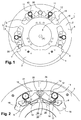
- Each window 19 has a contour 16 closed and part of this contour 16 defines a first raceway 12 secured to the support 2, on which one of the rolling members 11 received in this window 19 will roll, while another part of this closed contour 16 defines another first rolling track 12 secured to the support 2, on which the other rolling member 11 received in the window 19 will roll.
- Each connecting member 6 defines in the example of Figures 1 to 6 a second rolling track 13 which is integral with the pendular body 3 to which this connecting member 6 belongs and on which rolls one of the rolling members 11 to guide the displacement of the pendulum body 3 relative to the support 2.
- Each connecting member 6 has on its radially inner edge a notch 17 in which an abutment damper 18, for example elastomer or rubber, is received.
- each window 19 furthermore receives an interposing member 20.
- This interposing member 20 is arranged in the window 19 so as to be interposed between the two pendulous bodies 3 whose displacement relative to the support 2 is guided by a rolling member 11 received in this window 19.
- Each interposition member 20 here has a circular cross section, just like each rolling member 11.
- This interposing member 20 thus allows a minimum non-zero gap exists permanently between these two pendulums 3 neighboring circumferentially.
- the device 1 is at rest and the interposition member 20 comes into contact with the edge of the portion of one of the two pendulous bodies 3, and the edge of the portion of the other of the two pendulous bodies 3 while a clearance exists between the interposing member 20 and the portion of the contour 16 of the window 19.
- the pendular bodies 3 When a torsional oscillation is filtered by the pendular bodies 3, the latter move around the axis X of rotation of the support 2, and where appropriate around their center of gravity. Such displacement of the pendular bodies 3 is transmitted to the interposing members 20 which roll along said portion of the contour 16 of the window 19 and along a portion belonging to one of the two pendulous bodies 3 between which they are interposed.
- This cooperation between interposing members 20 and pendular bodies 3 allows the maintenance, via the interposing members 20, of a minimum distance between the two pendulous bodies 3.
- each interposing member 20 can come simultaneously. in contact with the portion 19 of the contour 16 of the window, the portion belonging to one of the two pendulous bodies 3 and the portion belonging to the other of the pendular bodies 3.
- the portion of the contour 16 of the window 19 of the support 2 with which comes into contact with the interposing member 20 and along which it can roll belongs to the radially outer edge 21 of the window 19.
- the interposition member 20 then simultaneously comes into contact with this portion of the edge 21, the edge of the portion of one of the two pendulous bodies 3, and the edge of the portion of the other of the two pendulum bodies 3 intermittently. when a torsional oscillation is filtered.
- the interposition member can then be placed partly inside a pendular body in the space left free by the fact that the pendulum masses 5 of a pendulum body 3 extend angularly beyond the connecting members 6.
- each interposing member 20 comprises a single diameter throughout its entire length.
- each interposition member 20 is made of two materials.
- the core 30 of this interposition member is made of a first material distinct from the second material which is used to produce the outer portion 31 of this interposition member 20.
- the first material is for example lighter than the second material.
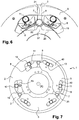
- a stop damping member 38 is provided in each window 19. This abutment damping member 38 is radially disposed between the radially inner edge 25 of the window 19 and the interposing member 20 and has a section transverse cylindrical.
- This abutment damping member 38 is made of rubber or elastomer and is capable of compressing during contact with the radially inner edge 25 of the window 19. This damping member 38 can thus cooperate with the damping abutment 18 mentioned above for damping shocks related to the abutment of the pendulum body 3 against the support 2.
- this abutment damping member 38 is in the described example not integral with the pendular bodies 3, the support 2 or the interposing member 20.
- the abutment damping member 38 comes through example in contact simultaneously with the radially inner edge 25 of the window 19, the interposing member 20 and each pendulum body 3 when it dampens the abutment of these pendular bodies 3 against the support 2.
- each of these cavities 60 has a dimension allowing it to accommodate the abutment damping member 38.
- Each cavity is in the example considered radially. disposed between the axis of rotation X and one of the rolling members 11 received in the window 19 when the device 1 is at rest.
- One of the cavities 60 accommodates the abutment damping member 38 during the abutment of the pendular bodies 3 against the support 2 at the end of a displacement of these pendulum bodies 3 in the trigonometric direction to filter a torsional oscillation, while the other cavity 60 formed in the radially inner edge 25 of the window 19 accommodates the abutment damping member 38 at the abutment of the pendular bodies 3 against the support 2 at the end of a displacement of these pendulum bodies 3 in the non-trigonometric direction to filter a torsion oscillation.
- the abutment damping member 38 is free to move in the window 19, its movement in this window 19 being here limited only by the comings in contact with this edge 25 of the window 19, the pendular bodies 3 and the interposition member 20.
- the portion of one of the two pendulous bodies 3 along which the interposing member 20 rolls is formed by a portion of the circumferential end 7 of the first pendulum mass 5 and a portion of the circumferential end 7 of the second pendulum mass 5 of one of these two pendulous bodies 3.
- each interposition member has several distinct diameters succeeding one another.
- the medial portion of the interposing member 20 thus has a diameter greater than that of the end portions.
- each interposing member 20 is adapted to come into contact with the radially inner edge 25 of the window 19 and to roll along a portion of this edge 25 when the pendular bodies 3 move due to an oscillation of torsion seen by the device 1.
- the interposing member 20 then simultaneously comes into contact with this portion of the edge 25, one of the two pendulous bodies 3, and the other of the two pendulum bodies 3 at least when the engine of the vehicle is stopped.
- the radially inner edge 25 of the window 19 may define a protuberance 37 protruding radially in the window 19, and the interposition member 20 rests against this protuberance when the engine of the vehicle is stopped.
- This protrusion 37 has a rounded shape in the plane of the figure 6 , and this shape is chosen so that the interposing member 20 remains at a constant distance from the edge of this protrusion when it moves in the window 19 under the effect of the displacement of the two pendulum bodies 3, as long as the latter are not out of sync.
- the portion of one of the two pendulous bodies 3 along which the interposing member 20 rolls is formed by a portion of the circumferential end 7 of the first pendulum mass 5 and a portion of the circumferential end 7 of the second pendulum mass 5 of one of these two pendulum bodies 3.
- the portion of the other of the two pendulous bodies 3 along which the interposition member 20 rolls is formed by a part the circumferential end 8 of the first pendulum mass 5 and a portion of the circumferential end 8 of the second pendulum mass 5 of the other of these two pendulum bodies 3.
- each rolling member 11 cooperates with two second tracks of bearing 13 distinct and integral with a pendulum 3.
- one of the pendular bodies 3 is not completely represented.
- One of the second race tracks 13 is defined by the first pendulum mass 5 of the pendulum body 3 and the other of these second raceways 13 is defined by the second pendulum mass 5 of the pendulum body 3.
- Each pendulum 5 presents in this example two cavities 40, and each of these cavities 40 receives a portion of a rolling member 11 which cooperates with the second raceway 13 formed by a portion of the contour of this cavity 40.
- the first rolling track 12 with which this rolling member 11 cooperates is, as previously, formed by a portion of the contour 16 of the window 19.
- each connecting member 6 is a rivet which is also received in the window 19.
- the portion of one of the two pendulous bodies 3 along which the interposing member 20 rolls is formed by a portion of the circumferential end 7 of the first pendulum mass 5 and a portion of the circumferential end 7 of the second pendulum mass 5 of this pendulum body 3, and the portion of the other of the two pendulum bodies 3 along which the interposition member 20 rolls is formed by a portion of the circumferential end 8 of the first pendulum mass and a portion of the circumferential end 8 of the second pendulum mass 5 of the other pendulous body 3, and these circumferential ends 7 and 8 are opposite.
- the interposition member comes into contact only with the first pendulum mass of one of the two pendular bodies and with the first pendulum mass of the other of the two pendular bodies. In another variant, the interposition member only comes into contact with the second pendulum mass of one of the two pendular bodies and the second pendulum mass of the other of the two pendular bodies.
- each pendulum body 3 comprises two paired pendulum masses and each extending on one side 4 of the support 2.
- the device comprises two separate supports 2 axially offset and secured.
- Each pendulum body 3 further comprises, in the example described, a single pendulum mass 5 arranged axially between the two supports 2.
- each pendulum body 3 having an outgrowth 45 projecting axially in a window 19 of one of the supports 2.
- This protrusion 45 which may or may not be made in one piece with the pendulum mass 5 of the pendulum body 3, defines here a second rolling track 13 integral with the pendulum body.
- two protuberances 45 are provided on each side of a pendulum mass 5. From one side to the other of the pendulum mass 5, these protuberances here extend axially in opposite directions and they are axially superimposed. Two axially superimposed projections 45 may be connected together and to the pendulum mass 5 via rivets 46, as shown in FIGS. Figures 8 and 9 .
- the two protuberances 45 formed on a first side of the pendulum mass 5 then project into two different windows 19 of one of the supports 2 while the two protuberances 45 formed on a second side of the pendulum mass 5, opposite at the first side, then protrude into two different windows 19 of the other of the two supports 2 of the device 1.
- the other of these interposing members 20 is disposed on the second side of the pendulum masses 5.
- the portion of one of the two pendulous bodies 3 with which the interposition member comes into contact is formed by a portion of the circumferential end 7 of the pendulum mass 5 of one of the two pendulum bodies 3, and the portion of the other of the two pendulous bodies 3 along which the interposition member 20 rolls is formed by a portion of the circumferential end 8 of the pendulous mass 5 of the other of the two pendulous bodies. 3, these circumferential ends 7 and 8 being opposite.
- each interposing member 20 cooperates with the two supports 2 and with two circumferentially adjacent pendular bodies 3.
- the figures 1 , 7 and 9 to 13 are scale views, so that measurements can be obtained from them by the skilled person.
Applications Claiming Priority (1)
| Application Number | Priority Date | Filing Date | Title |
|---|---|---|---|
| FR1557542A FR3039870B1 (fr) | 2015-08-05 | 2015-08-05 | Dispositif d'amortissement d'oscillations de torsion |
Publications (2)
| Publication Number | Publication Date |
|---|---|
| EP3128204A1 true EP3128204A1 (de) | 2017-02-08 |
| EP3128204B1 EP3128204B1 (de) | 2017-12-13 |
Family
ID=54937228
Family Applications (1)
| Application Number | Title | Priority Date | Filing Date |
|---|---|---|---|
| EP16178201.6A Active EP3128204B1 (de) | 2015-08-05 | 2016-07-06 | Vorrichtung zur torsionsschwingungsdämpfung |
Country Status (4)
| Country | Link |
|---|---|
| US (1) | US20170037930A1 (de) |
| EP (1) | EP3128204B1 (de) |
| CN (1) | CN106438838A (de) |
| FR (1) | FR3039870B1 (de) |
Cited By (1)
| Publication number | Priority date | Publication date | Assignee | Title |
|---|---|---|---|---|
| FR3114627A1 (fr) * | 2020-09-29 | 2022-04-01 | Valeo Embrayages | Dispositif d’amortissement pendulaire |
Families Citing this family (5)
| Publication number | Priority date | Publication date | Assignee | Title |
|---|---|---|---|---|
| KR101694049B1 (ko) * | 2015-08-24 | 2017-01-09 | 현대자동차주식회사 | 차량용 진동 저감 장치 |
| FR3070737B1 (fr) * | 2017-09-06 | 2019-08-23 | Valeo Embrayages | Dispositif damortissement pendulaire |
| DE102018201199A1 (de) * | 2018-01-26 | 2019-08-01 | Zf Friedrichshafen Ag | Tilgersystem |
| JP6764430B2 (ja) * | 2018-02-21 | 2020-09-30 | 株式会社エクセディ | トルク変動抑制装置、トルクコンバータ、及び動力伝達装置 |
| CN114688213A (zh) * | 2020-12-31 | 2022-07-01 | 法雷奥凯佩科液力变矩器(南京)有限公司 | 摆动式减振装置和包括其的机动车辆 |
Citations (4)
| Publication number | Priority date | Publication date | Assignee | Title |
|---|---|---|---|---|
| DE102011086532A1 (de) | 2010-12-15 | 2012-06-21 | Schaeffler Technologies Gmbh & Co. Kg | Fliehkraftpendel und Kupplungsscheibe mit demselben |
| WO2013174616A1 (fr) * | 2012-05-21 | 2013-11-28 | Valeo Embrayages | Dispositif de transmission de couple pour vehicule automobile |
| DE102012221103A1 (de) | 2012-11-19 | 2014-05-22 | Schaeffler Technologies Gmbh & Co. Kg | Fliehkraftpendeleinrichtung |
| FR3000157A1 (fr) * | 2012-12-20 | 2014-06-27 | Valeo Embrayages | Dispositifs d'amortissement de type oscillateur pendulaire destines a equiper les transmissions de vehicule automobile |
Family Cites Families (11)
| Publication number | Priority date | Publication date | Assignee | Title |
|---|---|---|---|---|
| US2343421A (en) * | 1942-07-31 | 1944-03-07 | Fairbanks Morse & Co | Torsional vibration damper |
| CN102792057B (zh) * | 2010-03-11 | 2015-06-24 | 舍弗勒技术股份两合公司 | 扭转振动减振器 |
| DE112011100857B4 (de) * | 2010-03-11 | 2018-12-13 | Schaeffler Technologies AG & Co. KG | Fliehkraftpendeleinrichtung |
| DE112011102741A5 (de) * | 2010-08-19 | 2013-07-04 | Schaeffler Technologies AG & Co. KG | Fliehkraftpendeleinrichtung |
| WO2012083920A1 (de) * | 2010-12-23 | 2012-06-28 | Schaeffler Technologies AG & Co. KG | Fliehkraftpendeleinrichtung |
| DE112012004941A5 (de) * | 2011-11-28 | 2014-08-28 | Schaeffler Technologies AG & Co. KG | Fliehkraftpendel |
| FR2989753B1 (fr) * | 2012-04-20 | 2014-04-18 | Valeo Embrayages | Dispositif d'amortissement pendulaire, en particulier pour une transmission de vehicule automobile |
| DE102012219738A1 (de) * | 2012-10-29 | 2014-04-30 | Zf Friedrichshafen Ag | Torsionsschwingungsdämpfer |
| FR3001507B1 (fr) * | 2013-01-28 | 2015-06-26 | Ntn Snr Roulements | Palier a roulement comprenant un capot solidaire de l’organe fixe |
| DE102014208569A1 (de) * | 2013-06-07 | 2014-12-11 | Schaeffler Technologies Gmbh & Co. Kg | Drehschwingungsdämpfer |
| WO2015149794A1 (de) * | 2014-04-02 | 2015-10-08 | Schaeffler Technologies AG & Co. KG | Fliehkraftpendeleinrichtung und drehschwingungsdämpfer |
-
2015
- 2015-08-05 FR FR1557542A patent/FR3039870B1/fr not_active Expired - Fee Related
-
2016
- 2016-07-06 EP EP16178201.6A patent/EP3128204B1/de active Active
- 2016-08-03 US US15/227,388 patent/US20170037930A1/en not_active Abandoned
- 2016-08-04 CN CN201610633071.4A patent/CN106438838A/zh active Pending
Patent Citations (4)
| Publication number | Priority date | Publication date | Assignee | Title |
|---|---|---|---|---|
| DE102011086532A1 (de) | 2010-12-15 | 2012-06-21 | Schaeffler Technologies Gmbh & Co. Kg | Fliehkraftpendel und Kupplungsscheibe mit demselben |
| WO2013174616A1 (fr) * | 2012-05-21 | 2013-11-28 | Valeo Embrayages | Dispositif de transmission de couple pour vehicule automobile |
| DE102012221103A1 (de) | 2012-11-19 | 2014-05-22 | Schaeffler Technologies Gmbh & Co. Kg | Fliehkraftpendeleinrichtung |
| FR3000157A1 (fr) * | 2012-12-20 | 2014-06-27 | Valeo Embrayages | Dispositifs d'amortissement de type oscillateur pendulaire destines a equiper les transmissions de vehicule automobile |
Cited By (2)
| Publication number | Priority date | Publication date | Assignee | Title |
|---|---|---|---|---|
| FR3114627A1 (fr) * | 2020-09-29 | 2022-04-01 | Valeo Embrayages | Dispositif d’amortissement pendulaire |
| WO2022069497A1 (fr) * | 2020-09-29 | 2022-04-07 | Valeo Embrayages | Dispositif d'amortissement pendulaire |
Also Published As
| Publication number | Publication date |
|---|---|
| CN106438838A (zh) | 2017-02-22 |
| FR3039870A1 (fr) | 2017-02-10 |
| EP3128204B1 (de) | 2017-12-13 |
| US20170037930A1 (en) | 2017-02-09 |
| FR3039870B1 (fr) | 2017-07-28 |
Similar Documents
| Publication | Publication Date | Title |
|---|---|---|
| EP3190310B1 (de) | Pendel-dämpfungsvorrichtung | |
| EP3128204B1 (de) | Vorrichtung zur torsionsschwingungsdämpfung | |
| EP3332147B1 (de) | Vorrichtung zur dämpfung von torsionsschwingungen | |
| EP3380750B1 (de) | Pendeldämpfungsvorrichtung | |
| EP3026295B1 (de) | Vorrichtung zur torsionsschwingungsdämpfung | |
| EP3101312B1 (de) | Vorrichtung zur torsionsschwingungsdämpfung | |
| EP3207278B1 (de) | Vorrichtung zur dämpfung von torsionsschwingungen | |
| EP3153741A1 (de) | Vorrichtung zur torsionsschwingungsdämpfung | |
| FR3046649A1 (fr) | Dispositif d'amortissement pendulaire | |
| EP3101311B1 (de) | Vorrichtung zur torsionsschwingungsdämpfung | |
| FR3050500A1 (fr) | Dispositif d'amortissement pendulaire | |
| EP3115639B2 (de) | Vorrichtung zur torsionsschwingungsdämpfung | |
| EP3163118B1 (de) | Vorrichtung zur torsionsschwingungsdämpfung | |
| FR3025275A1 (fr) | Dispositif d'amortissement d'oscillations de torsion | |
| FR3046648A1 (fr) | Dispositif d'amortissement pendulaire | |
| EP3207279B1 (de) | Vorrichtung zur dämpfung von torsionsschwingungen | |
| WO2019154668A1 (fr) | Dispositif d'amortissement pendulaire | |
| FR3033860B1 (fr) | Dispositif d'amortissement d'oscillations de torsion | |
| FR3059750B1 (fr) | Dispositif d'amortissement pendulaire | |
| FR3029253A1 (fr) | Dispositif d'amortissement d'oscillations de torsion | |
| FR3029254A1 (fr) | Dispositif d'amortissement d'oscillations de torsion | |
| FR3130343A1 (fr) | Dispositif d’amortissement pendulaire | |
| WO2020126607A1 (fr) | Dispositif d'amortissement pendulaire |
Legal Events
| Date | Code | Title | Description |
|---|---|---|---|
| PUAI | Public reference made under article 153(3) epc to a published international application that has entered the european phase |
Free format text: ORIGINAL CODE: 0009012 |
|
| 17P | Request for examination filed |
Effective date: 20160706 |
|
| AK | Designated contracting states |
Kind code of ref document: A1 Designated state(s): AL AT BE BG CH CY CZ DE DK EE ES FI FR GB GR HR HU IE IS IT LI LT LU LV MC MK MT NL NO PL PT RO RS SE SI SK SM TR |
|
| AX | Request for extension of the european patent |
Extension state: BA ME |
|
| RIC1 | Information provided on ipc code assigned before grant |
Ipc: F16F 15/14 20060101AFI20170627BHEP |
|
| GRAP | Despatch of communication of intention to grant a patent |
Free format text: ORIGINAL CODE: EPIDOSNIGR1 |
|
| INTG | Intention to grant announced |
Effective date: 20170817 |
|
| GRAS | Grant fee paid |
Free format text: ORIGINAL CODE: EPIDOSNIGR3 |
|
| GRAA | (expected) grant |
Free format text: ORIGINAL CODE: 0009210 |
|
| REG | Reference to a national code |
Ref country code: GB Ref legal event code: FG4D Free format text: NOT ENGLISH |
|
| REG | Reference to a national code |
Ref country code: AT Ref legal event code: REF Ref document number: 954717 Country of ref document: AT Kind code of ref document: T Effective date: 20171215 Ref country code: CH Ref legal event code: EP |
|
| REG | Reference to a national code |
Ref country code: IE Ref legal event code: FG4D Free format text: LANGUAGE OF EP DOCUMENT: FRENCH |
|
| REG | Reference to a national code |
Ref country code: DE Ref legal event code: R096 Ref document number: 602016001079 Country of ref document: DE |
|
| REG | Reference to a national code |
Ref country code: NL Ref legal event code: MP Effective date: 20171213 |
|
| PG25 | Lapsed in a contracting state [announced via postgrant information from national office to epo] |
Ref country code: SE Free format text: LAPSE BECAUSE OF FAILURE TO SUBMIT A TRANSLATION OF THE DESCRIPTION OR TO PAY THE FEE WITHIN THE PRESCRIBED TIME-LIMIT Effective date: 20171213 Ref country code: NO Free format text: LAPSE BECAUSE OF FAILURE TO SUBMIT A TRANSLATION OF THE DESCRIPTION OR TO PAY THE FEE WITHIN THE PRESCRIBED TIME-LIMIT Effective date: 20180313 Ref country code: FI Free format text: LAPSE BECAUSE OF FAILURE TO SUBMIT A TRANSLATION OF THE DESCRIPTION OR TO PAY THE FEE WITHIN THE PRESCRIBED TIME-LIMIT Effective date: 20171213 |
|
| REG | Reference to a national code |
Ref country code: AT Ref legal event code: MK05 Ref document number: 954717 Country of ref document: AT Kind code of ref document: T Effective date: 20171213 |
|
| PG25 | Lapsed in a contracting state [announced via postgrant information from national office to epo] |
Ref country code: RS Free format text: LAPSE BECAUSE OF FAILURE TO SUBMIT A TRANSLATION OF THE DESCRIPTION OR TO PAY THE FEE WITHIN THE PRESCRIBED TIME-LIMIT Effective date: 20171213 Ref country code: HR Free format text: LAPSE BECAUSE OF FAILURE TO SUBMIT A TRANSLATION OF THE DESCRIPTION OR TO PAY THE FEE WITHIN THE PRESCRIBED TIME-LIMIT Effective date: 20171213 Ref country code: GR Free format text: LAPSE BECAUSE OF FAILURE TO SUBMIT A TRANSLATION OF THE DESCRIPTION OR TO PAY THE FEE WITHIN THE PRESCRIBED TIME-LIMIT Effective date: 20180314 Ref country code: BG Free format text: LAPSE BECAUSE OF FAILURE TO SUBMIT A TRANSLATION OF THE DESCRIPTION OR TO PAY THE FEE WITHIN THE PRESCRIBED TIME-LIMIT Effective date: 20180313 Ref country code: LV Free format text: LAPSE BECAUSE OF FAILURE TO SUBMIT A TRANSLATION OF THE DESCRIPTION OR TO PAY THE FEE WITHIN THE PRESCRIBED TIME-LIMIT Effective date: 20171213 |
|
| PG25 | Lapsed in a contracting state [announced via postgrant information from national office to epo] |
Ref country code: NL Free format text: LAPSE BECAUSE OF FAILURE TO SUBMIT A TRANSLATION OF THE DESCRIPTION OR TO PAY THE FEE WITHIN THE PRESCRIBED TIME-LIMIT Effective date: 20171213 |
|
| REG | Reference to a national code |
Ref country code: FR Ref legal event code: PLFP Year of fee payment: 3 |
|
| PG25 | Lapsed in a contracting state [announced via postgrant information from national office to epo] |
Ref country code: ES Free format text: LAPSE BECAUSE OF FAILURE TO SUBMIT A TRANSLATION OF THE DESCRIPTION OR TO PAY THE FEE WITHIN THE PRESCRIBED TIME-LIMIT Effective date: 20171213 Ref country code: CZ Free format text: LAPSE BECAUSE OF FAILURE TO SUBMIT A TRANSLATION OF THE DESCRIPTION OR TO PAY THE FEE WITHIN THE PRESCRIBED TIME-LIMIT Effective date: 20171213 Ref country code: SK Free format text: LAPSE BECAUSE OF FAILURE TO SUBMIT A TRANSLATION OF THE DESCRIPTION OR TO PAY THE FEE WITHIN THE PRESCRIBED TIME-LIMIT Effective date: 20171213 Ref country code: CY Free format text: LAPSE BECAUSE OF FAILURE TO SUBMIT A TRANSLATION OF THE DESCRIPTION OR TO PAY THE FEE WITHIN THE PRESCRIBED TIME-LIMIT Effective date: 20171213 Ref country code: EE Free format text: LAPSE BECAUSE OF FAILURE TO SUBMIT A TRANSLATION OF THE DESCRIPTION OR TO PAY THE FEE WITHIN THE PRESCRIBED TIME-LIMIT Effective date: 20171213 |
|
| PG25 | Lapsed in a contracting state [announced via postgrant information from national office to epo] |
Ref country code: PL Free format text: LAPSE BECAUSE OF FAILURE TO SUBMIT A TRANSLATION OF THE DESCRIPTION OR TO PAY THE FEE WITHIN THE PRESCRIBED TIME-LIMIT Effective date: 20171213 Ref country code: IS Free format text: LAPSE BECAUSE OF FAILURE TO SUBMIT A TRANSLATION OF THE DESCRIPTION OR TO PAY THE FEE WITHIN THE PRESCRIBED TIME-LIMIT Effective date: 20180413 Ref country code: IT Free format text: LAPSE BECAUSE OF FAILURE TO SUBMIT A TRANSLATION OF THE DESCRIPTION OR TO PAY THE FEE WITHIN THE PRESCRIBED TIME-LIMIT Effective date: 20171213 Ref country code: SM Free format text: LAPSE BECAUSE OF FAILURE TO SUBMIT A TRANSLATION OF THE DESCRIPTION OR TO PAY THE FEE WITHIN THE PRESCRIBED TIME-LIMIT Effective date: 20171213 Ref country code: AT Free format text: LAPSE BECAUSE OF FAILURE TO SUBMIT A TRANSLATION OF THE DESCRIPTION OR TO PAY THE FEE WITHIN THE PRESCRIBED TIME-LIMIT Effective date: 20171213 |
|
| REG | Reference to a national code |
Ref country code: DE Ref legal event code: R097 Ref document number: 602016001079 Country of ref document: DE |
|
| PG25 | Lapsed in a contracting state [announced via postgrant information from national office to epo] |
Ref country code: MT Free format text: LAPSE BECAUSE OF FAILURE TO SUBMIT A TRANSLATION OF THE DESCRIPTION OR TO PAY THE FEE WITHIN THE PRESCRIBED TIME-LIMIT Effective date: 20171213 |
|
| PLBE | No opposition filed within time limit |
Free format text: ORIGINAL CODE: 0009261 |
|
| STAA | Information on the status of an ep patent application or granted ep patent |
Free format text: STATUS: NO OPPOSITION FILED WITHIN TIME LIMIT |
|
| PGFP | Annual fee paid to national office [announced via postgrant information from national office to epo] |
Ref country code: FR Payment date: 20180727 Year of fee payment: 3 |
|
| 26N | No opposition filed |
Effective date: 20180914 |
|
| PG25 | Lapsed in a contracting state [announced via postgrant information from national office to epo] |
Ref country code: DK Free format text: LAPSE BECAUSE OF FAILURE TO SUBMIT A TRANSLATION OF THE DESCRIPTION OR TO PAY THE FEE WITHIN THE PRESCRIBED TIME-LIMIT Effective date: 20171213 |
|
| PG25 | Lapsed in a contracting state [announced via postgrant information from national office to epo] |
Ref country code: SI Free format text: LAPSE BECAUSE OF FAILURE TO SUBMIT A TRANSLATION OF THE DESCRIPTION OR TO PAY THE FEE WITHIN THE PRESCRIBED TIME-LIMIT Effective date: 20171213 |
|
| PG25 | Lapsed in a contracting state [announced via postgrant information from national office to epo] |
Ref country code: LU Free format text: LAPSE BECAUSE OF NON-PAYMENT OF DUE FEES Effective date: 20180706 Ref country code: MC Free format text: LAPSE BECAUSE OF FAILURE TO SUBMIT A TRANSLATION OF THE DESCRIPTION OR TO PAY THE FEE WITHIN THE PRESCRIBED TIME-LIMIT Effective date: 20171213 |
|
| REG | Reference to a national code |
Ref country code: BE Ref legal event code: MM Effective date: 20180731 |
|
| REG | Reference to a national code |
Ref country code: IE Ref legal event code: MM4A |
|
| PG25 | Lapsed in a contracting state [announced via postgrant information from national office to epo] |
Ref country code: IE Free format text: LAPSE BECAUSE OF NON-PAYMENT OF DUE FEES Effective date: 20180706 |
|
| PG25 | Lapsed in a contracting state [announced via postgrant information from national office to epo] |
Ref country code: BE Free format text: LAPSE BECAUSE OF NON-PAYMENT OF DUE FEES Effective date: 20180731 |
|
| REG | Reference to a national code |
Ref country code: CH Ref legal event code: PL |
|
| PG25 | Lapsed in a contracting state [announced via postgrant information from national office to epo] |
Ref country code: TR Free format text: LAPSE BECAUSE OF FAILURE TO SUBMIT A TRANSLATION OF THE DESCRIPTION OR TO PAY THE FEE WITHIN THE PRESCRIBED TIME-LIMIT Effective date: 20171213 |
|
| PG25 | Lapsed in a contracting state [announced via postgrant information from national office to epo] |
Ref country code: LI Free format text: LAPSE BECAUSE OF NON-PAYMENT OF DUE FEES Effective date: 20190731 Ref country code: PT Free format text: LAPSE BECAUSE OF FAILURE TO SUBMIT A TRANSLATION OF THE DESCRIPTION OR TO PAY THE FEE WITHIN THE PRESCRIBED TIME-LIMIT Effective date: 20171213 Ref country code: CH Free format text: LAPSE BECAUSE OF NON-PAYMENT OF DUE FEES Effective date: 20190731 |
|
| PG25 | Lapsed in a contracting state [announced via postgrant information from national office to epo] |
Ref country code: HU Free format text: LAPSE BECAUSE OF FAILURE TO SUBMIT A TRANSLATION OF THE DESCRIPTION OR TO PAY THE FEE WITHIN THE PRESCRIBED TIME-LIMIT; INVALID AB INITIO Effective date: 20160706 Ref country code: LT Free format text: LAPSE BECAUSE OF FAILURE TO SUBMIT A TRANSLATION OF THE DESCRIPTION OR TO PAY THE FEE WITHIN THE PRESCRIBED TIME-LIMIT Effective date: 20171213 Ref country code: RO Free format text: LAPSE BECAUSE OF FAILURE TO SUBMIT A TRANSLATION OF THE DESCRIPTION OR TO PAY THE FEE WITHIN THE PRESCRIBED TIME-LIMIT Effective date: 20171213 Ref country code: FR Free format text: LAPSE BECAUSE OF NON-PAYMENT OF DUE FEES Effective date: 20190731 Ref country code: MK Free format text: LAPSE BECAUSE OF NON-PAYMENT OF DUE FEES Effective date: 20171213 |
|
| PG25 | Lapsed in a contracting state [announced via postgrant information from national office to epo] |
Ref country code: AL Free format text: LAPSE BECAUSE OF FAILURE TO SUBMIT A TRANSLATION OF THE DESCRIPTION OR TO PAY THE FEE WITHIN THE PRESCRIBED TIME-LIMIT Effective date: 20171213 |
|
| GBPC | Gb: european patent ceased through non-payment of renewal fee |
Effective date: 20200706 |
|
| PG25 | Lapsed in a contracting state [announced via postgrant information from national office to epo] |
Ref country code: GB Free format text: LAPSE BECAUSE OF NON-PAYMENT OF DUE FEES Effective date: 20200706 |
|
| P01 | Opt-out of the competence of the unified patent court (upc) registered |
Effective date: 20230528 |
|
| PGFP | Annual fee paid to national office [announced via postgrant information from national office to epo] |
Ref country code: DE Payment date: 20230712 Year of fee payment: 8 |