EP3128082A1 - Pneumatic fender and pneumatic fender mouthpiece - Google Patents
Pneumatic fender and pneumatic fender mouthpiece Download PDFInfo
- Publication number
- EP3128082A1 EP3128082A1 EP15773754.5A EP15773754A EP3128082A1 EP 3128082 A1 EP3128082 A1 EP 3128082A1 EP 15773754 A EP15773754 A EP 15773754A EP 3128082 A1 EP3128082 A1 EP 3128082A1
- Authority
- EP
- European Patent Office
- Prior art keywords
- open
- receiving chamber
- fender
- hole
- cavity
- Prior art date
- Legal status (The legal status is an assumption and is not a legal conclusion. Google has not performed a legal analysis and makes no representation as to the accuracy of the status listed.)
- Granted
Links
- 239000002184 metal Substances 0.000 claims abstract description 63
- 239000000463 material Substances 0.000 claims description 9
- 238000012790 confirmation Methods 0.000 abstract description 10
- 238000012360 testing method Methods 0.000 abstract description 10
- 230000002093 peripheral effect Effects 0.000 description 4
- 238000012423 maintenance Methods 0.000 description 3
- 238000004140 cleaning Methods 0.000 description 2
- 230000013011 mating Effects 0.000 description 2
- 125000006850 spacer group Chemical group 0.000 description 2
- 238000007599 discharging Methods 0.000 description 1
- 230000000694 effects Effects 0.000 description 1
- 239000012530 fluid Substances 0.000 description 1
- 239000012779 reinforcing material Substances 0.000 description 1
- 230000035939 shock Effects 0.000 description 1
- XLYOFNOQVPJJNP-UHFFFAOYSA-N water Substances O XLYOFNOQVPJJNP-UHFFFAOYSA-N 0.000 description 1
Images


Classifications
-
- E—FIXED CONSTRUCTIONS
- E02—HYDRAULIC ENGINEERING; FOUNDATIONS; SOIL SHIFTING
- E02B—HYDRAULIC ENGINEERING
- E02B3/00—Engineering works in connection with control or use of streams, rivers, coasts, or other marine sites; Sealings or joints for engineering works in general
- E02B3/20—Equipment for shipping on coasts, in harbours or on other fixed marine structures, e.g. bollards
- E02B3/26—Fenders
-
- B—PERFORMING OPERATIONS; TRANSPORTING
- B63—SHIPS OR OTHER WATERBORNE VESSELS; RELATED EQUIPMENT
- B63B—SHIPS OR OTHER WATERBORNE VESSELS; EQUIPMENT FOR SHIPPING
- B63B59/00—Hull protection specially adapted for vessels; Cleaning devices specially adapted for vessels
- B63B59/02—Fenders integral with waterborne vessels or specially adapted therefor, e.g. fenders forming part of the hull or incorporated in the hull; Rubbing-strakes
-
- F—MECHANICAL ENGINEERING; LIGHTING; HEATING; WEAPONS; BLASTING
- F16—ENGINEERING ELEMENTS AND UNITS; GENERAL MEASURES FOR PRODUCING AND MAINTAINING EFFECTIVE FUNCTIONING OF MACHINES OR INSTALLATIONS; THERMAL INSULATION IN GENERAL
- F16K—VALVES; TAPS; COCKS; ACTUATING-FLOATS; DEVICES FOR VENTING OR AERATING
- F16K1/00—Lift valves or globe valves, i.e. cut-off apparatus with closure members having at least a component of their opening and closing motion perpendicular to the closing faces
-
- F—MECHANICAL ENGINEERING; LIGHTING; HEATING; WEAPONS; BLASTING
- F16—ENGINEERING ELEMENTS AND UNITS; GENERAL MEASURES FOR PRODUCING AND MAINTAINING EFFECTIVE FUNCTIONING OF MACHINES OR INSTALLATIONS; THERMAL INSULATION IN GENERAL
- F16K—VALVES; TAPS; COCKS; ACTUATING-FLOATS; DEVICES FOR VENTING OR AERATING
- F16K17/00—Safety valves; Equalising valves, e.g. pressure relief valves
- F16K17/02—Safety valves; Equalising valves, e.g. pressure relief valves opening on surplus pressure on one side; closing on insufficient pressure on one side
- F16K17/04—Safety valves; Equalising valves, e.g. pressure relief valves opening on surplus pressure on one side; closing on insufficient pressure on one side spring-loaded
- F16K17/044—Safety valves; Equalising valves, e.g. pressure relief valves opening on surplus pressure on one side; closing on insufficient pressure on one side spring-loaded with more than one spring
-
- F—MECHANICAL ENGINEERING; LIGHTING; HEATING; WEAPONS; BLASTING
- F16—ENGINEERING ELEMENTS AND UNITS; GENERAL MEASURES FOR PRODUCING AND MAINTAINING EFFECTIVE FUNCTIONING OF MACHINES OR INSTALLATIONS; THERMAL INSULATION IN GENERAL
- F16K—VALVES; TAPS; COCKS; ACTUATING-FLOATS; DEVICES FOR VENTING OR AERATING
- F16K17/00—Safety valves; Equalising valves, e.g. pressure relief valves
- F16K17/02—Safety valves; Equalising valves, e.g. pressure relief valves opening on surplus pressure on one side; closing on insufficient pressure on one side
- F16K17/04—Safety valves; Equalising valves, e.g. pressure relief valves opening on surplus pressure on one side; closing on insufficient pressure on one side spring-loaded
- F16K17/048—Safety valves; Equalising valves, e.g. pressure relief valves opening on surplus pressure on one side; closing on insufficient pressure on one side spring-loaded combined with other safety valves, or with pressure control devices
-
- B—PERFORMING OPERATIONS; TRANSPORTING
- B63—SHIPS OR OTHER WATERBORNE VESSELS; RELATED EQUIPMENT
- B63B—SHIPS OR OTHER WATERBORNE VESSELS; EQUIPMENT FOR SHIPPING
- B63B59/00—Hull protection specially adapted for vessels; Cleaning devices specially adapted for vessels
- B63B59/02—Fenders integral with waterborne vessels or specially adapted therefor, e.g. fenders forming part of the hull or incorporated in the hull; Rubbing-strakes
- B63B2059/025—Fenders integral with waterborne vessels or specially adapted therefor, e.g. fenders forming part of the hull or incorporated in the hull; Rubbing-strakes pneumatic, e.g. inflatable
-
- Y—GENERAL TAGGING OF NEW TECHNOLOGICAL DEVELOPMENTS; GENERAL TAGGING OF CROSS-SECTIONAL TECHNOLOGIES SPANNING OVER SEVERAL SECTIONS OF THE IPC; TECHNICAL SUBJECTS COVERED BY FORMER USPC CROSS-REFERENCE ART COLLECTIONS [XRACs] AND DIGESTS
- Y02—TECHNOLOGIES OR APPLICATIONS FOR MITIGATION OR ADAPTATION AGAINST CLIMATE CHANGE
- Y02A—TECHNOLOGIES FOR ADAPTATION TO CLIMATE CHANGE
- Y02A30/00—Adapting or protecting infrastructure or their operation
- Y02A30/30—Adapting or protecting infrastructure or their operation in transportation, e.g. on roads, waterways or railways
Definitions
- the present invention relates to a pneumatic fender and a mouth piece metal for a pneumatic fender, and further relates to a pneumatic fender and a mouth piece metal for a pneumatic fender with significantly enhanced maintainability wherein a safety valve can be detached and attached and a confirmation test of the valve opening pressure of the safety valve can be performed on the pneumatic fender while in use, and the labor and time required for these operations are greatly reduced.
- Pneumatic fenders are designed to have air sealed in the cavity of a fender bladder so as to be provided with predetermined performance such as shock absorbing performance. If the fender bladder remains sealed when the fender is excessively compressed, the internal pressure in the cavity may increase beyond a preset pressure threshold and cause failure of the fender bladder. To combat this, a safety valve that connects the cavity to the outside air may be provided on a mouth piece metal provided on the fender bladder for such cases when the internal pressure of the cavity of the fender bladder exceeds the pressure threshold (see, for example, Patent Document 1).
- Such a safety valve is routinely (for example, every 1 to 3 years) detached from the mouth piece metal for confirmation testing of the value opening pressure, cleaning, and other such maintenance.
- the cavity of the fender bladder of such a pneumatic fender when in use is inflated to a predetermined internal pressure, and so detaching the safety valve from the mouth piece metal of the fender bladder when the pneumatic fender is in use would result in air being violently ejected from the cavity.
- the detachment of the safety valve is not possible. Accordingly, the detachment of the safety valve is performed after sufficiently discharging the air from the cavity of the fender bladder.
- the in-use pneumatic fender is brought onto land or a marine vessel before the air is discharged.
- the safety valve Upon completion of the confirmation testing of the valve opening pressure, cleaning, and the like of the detached safety valve, the safety valve must be reattached to the mouth piece metal, the cavity of the fender bladder must be inflated with air, and the pneumatic fender must be installed in a predetermined position. Accordingly, the maintenance of detaching and attaching the safety valve to the mouth piece metal requires a great deal of man-hours and time.
- Patent Document 1 Japanese Unexamined Patent Application Publication No. 2003-129446A
- An object of the present invention is to provide a pneumatic fender and a mouth piece metal for a pneumatic fender with significantly enhanced maintainability wherein a safety valve can be attached and detached and a confirmation test of the valve opening pressure of the safety valve can be performed on the pneumatic fender while in use, and the labor and time required for these operations are greatly reduced.
- a pneumatic fender of the present invention comprises:
- a mouth piece metal for a pneumatic fender of the present invention is a mouth piece metal for a pneumatic fender attachable to a bowl-like hemispherical portion constituting a fender bladder, the mouth piece metal comprising:
- the mouth piece metal includes a receiving chamber that isolates the safety valve from the cavity of the fender bladder, a through hole that connects a cavity of the receiving chamber and the cavity of the fender bladder, the through hole being formed on a dividing wall constituting the receiving chamber, an open/close valve that opens and closes the through hole, a closed position fixing member that fixes the open/close valve at a position in which the through hole is closed, an open position fixing member that fixes the open/close valve at a position in which the through hole is open.
- the closed position fixing member and the open position fixing member are disposed outside of the receiving chamber at a position to a surface side of the mouth piece metal, thus when the open/close valve is fixed at a position in which the through hole is open by the open position fixing member, the cavity of the receiving chamber and the cavity of the fender bladder are connected. Fixing of the open position fixing member can be performed to the surface side of the mouth piece metal, i.e. outside of the fender bladder. In this state, the safety valve functions normally. This enables the safety valve to open, thus reducing the internal pressure of the cavity and preventing damage when the fender bladder is excessively compressed.
- the safety valve When the open/close valve is fixed at a position in which the through hole is closed by the closed position fixing member, the safety valve is isolated from the cavity of the fender bladder. Fixing of the closed position fixing member can be performed to the surface side of the mouth piece metal, i.e. outside of the fender bladder. In this state, the safety valve can be detached and attached from the mouth piece metal of an in-use pneumatic fender while in use without bringing the pneumatic fender onto land or a marine vessel.
- the mouth piece metal further includes the receiving chamber communication passage that connects the cavity of the receiving chamber and outside air and the receiving chamber open/close valve that opens and closes the receiving chamber communication passage.
- This configuration allows the safety valve to be isolated from the cavity of the fender bladder, thus allowing the receiving chamber open/close valve to be opened and the internal pressure of the cavity of the receiving chamber to be raised to the pressure threshold via the receiving chamber communication passage.
- a confirmation test of the valve opening pressure of the safety valve can be performed on the pneumatic fender while in use.
- the safety valve can be detached and attached and a confirmation test of the value opening pressure can be performed on the pneumatic fender while in use. As such, the labor and time required for these operations can be greatly reduced, and maintainability can be significantly enhanced.
- a pneumatic fender 1 (hereinafter, also fender 1) of the present invention illustrated in FIG. 1 to FIG. 5 includes a fender bladder 2 that is made mainly of rubber and has reinforcing material embedded therein.
- the fender bladder 2 is formed with a cylindrical portion 3a and a bowl-like hemispherical portion 3b on each end of the cylindrical portion 3a in the cylinder axial direction connected thereto.
- a mouth piece metal 4 of the present invention is provided on one of the hemispherical portions 3b.
- the mouth piece metal 4 may also be provided on the hemispherical portion 3b on both sides.
- the mouth piece metal 4 is a recessed cylinder-like fitting.
- the opening of the mouth piece metal 4 to the surface side may be covered by a lid attached by a bolt or the like.
- the mouth piece metal 4 includes a safety valve 6, a communication passage 11 that connects a cavity 2a of the fender bladder 2 to the outside air, and a bladder open/close valve 11a that opens and closes the communication passage 11. Additionally, the mouth piece metal 4 includes a receiving chamber 8 that isolates the safety valve 6 from the cavity 2a, a through hole 7a formed in a dividing wall 7 constituting the receiving chamber 8, an open/close valve 9 that opens and closes the through hole 7a, a receiving chamber communication passage 12 that connects a cavity 8a of the receiving chamber 8 to the outside air, and a receiving chamber open/close valve 12a that opens and closes the receiving chamber communication passage 12.
- the mouth piece metal 4 further includes closed position fixing members 5a and open position fixing members 5b.
- the receiving chamber 8 is formed extending toward the cavity 2a of the fender bladder 2 from a flat plate 4a on which the safety valve 6 is attached. In other words, the receiving chamber 8 is formed at a position to the back side of the mouth piece metal 4.
- the safety valve 6 is fixed to the flat plate 4a and extends through the flat plate 4a and into the cavity 8a of the receiving chamber 8.
- the communication passage 11 extends through the flat plate 4a and the receiving chamber 8 and terminates in the cavity 2a.
- the receiving chamber communication passage 12 extends through the flat plate 4a and terminates in the cavity 8a of the receiving chamber 8.
- the safety valve 6 opens when the pressure reaches a set pressure threshold Pm so that the fender bladder 2 is not damaged when excessively compressed and is closed when the pressure is less than the pressure threshold Pm.
- the safety valve 6 opens to connect the cavity 2a to the outside air when the internal pressure P of the cavity 2a of the fender bladder 2 reaches the pressure threshold Pm.
- the open/close valve 9 includes a shaft 9c and an outer flange 9a and an inner flange 9b fixed to either end of the shaft 9c.
- the outer flange 9a and the inner flange 9b are in an opposing configuration.
- the shaft 9c extends through the flat plate 4a and can slide freely in the cylinder axial direction of the fender bladder 2.
- the inner flange 9b is disposed in the cavity 8a of the receiving chamber 8.
- the outer flange 9a is disposed outside of the receiving chamber 8 at a position to the surface side of the mouth piece metal 4.
- the open/close valve 9 can slide freely in the direction in which it moves towards and away from the through hole 7a.
- the through hole 7a is open with the open/close valve 9 being fixed to the flat plate 4a at a position in which the through hole 7a is open by the open position fixing members 5b.
- the open position fixing members 5b are disposed outside of the receiving chamber 8 at a position to the surface side of the mouth piece metal 4.
- a seal material 10c is preferably disposed between the opposing surfaces to increase hermeticity.
- the seal material 10c is annular.
- the through hole 7a is closed with the open/close valve 9 being fixed to the flat plate 4a at a position in which the through hole 7a is closed by the closed position fixing members 5a.
- the closed position fixing members 5a are disposed outside of the receiving chamber 8 at a position to the surface side of the mouth piece metal 4.
- the seal material 10c is preferably disposed between the opposing surfaces to increase hermeticity.
- Closing position holes 10a and opening position holes 10b are alternately disposed in the outer flange 9a at intervals in the circumferential direction.
- the closing position holes 10a and the opening position holes 10b extend through the outer flange 9a in the sliding direction of the open/close valve 9.
- the closing position holes 10a are simple through holes and the opening position holes 10b are bolt holes.
- the closed position fixing members 5a are typical fixing bolts.
- the open position fixing members 5b are fixing bolts threaded from the bolt head portion about halfway down in the longitudinal direction.
- the open position fixing members 5b are screwed into the opening position holes 10b formed in the outer flange 9a, the tips of the open position fixing members 5b are brought into contact with the surface of the flat plate 4a, and the opposing surfaces of the inner flange 9b and the flat plate 4a are brought into hermetic contact.
- the closed position fixing members 5a are inserted in the closing position holes 10a formed in the outer flange 9a, the tips of the closed position fixing members 5a are screwed into bolt holes formed in the surface of the flat plate 4a, and the inner flange 9b and the dividing wall 7 (the dividing wall 7 positioned opposing the flat plate 4a) are brought into hermetic contact.
- the cavity 2a is given the predetermined initial internal pressure Pi by being inflated with air or filled with air and fluid (water).
- the pneumatic fender 1 is disposed at the place of use such as a wharf.
- the open/close valve 9 is fixed at a position in which the through hole 7a is open by the open position fixing members 5b. Accordingly, the cavity 2a of the fender bladder 2 and the cavity 8a of the receiving chamber 8 are connected via the through hole 7a and thus the cavities 2a, 8a become equal in internal pressure P.
- the internal pressure of the cavity 8a is also exceeded. This causes the safety valve 6 to open.
- the safety valve 6 functions as per convention to connect the cavity 2a to the outside air, thus reducing the internal pressure P of the cavity 2a to the pressure threshold Pm or less. As a result, damage to the fender bladder 2 can be prevented.
- the open/close valve 9 is fixed at a position in which the through hole 7a is closed by the closed position fixing members 5a.
- the safety valve 6 is isolated from the cavity 2a of the fender bladder 2 by the receiving chamber 8. Accordingly, the safety valve 6 can be safely detached from the mouth piece metal 4 and safely attached to the mouth piece metal 4.
- the safety valve 6 can be detached and attached from an in-use pneumatic fender 1 while in use without bringing the pneumatic fender 1 onto land or a marine vessel.
- the open/close valve 9 thus keeping the through hole 7a closed
- the receiving chamber open/close valve 12a by opening the receiving chamber open/close valve 12a and injecting compressed air into the cavity 8a of the receiving chamber 8 via the receiving chamber communication passage 12, the internal pressure of the cavity 8a can be raised to the pressure threshold Pm.
- a confirmation test of the valve opening pressure of the safety valve 6 can be performed on the pneumatic fender 1 while in use.
- the safety valve 6 can be detached and attached and a confirmation test of the valve opening pressure can be performed on the pneumatic fender 1 while in use.
- the labor and time required for these operations can be greatly reduced, and maintainability can be significantly enhanced.
- FIG. 6 Another embodiment of the mouth piece metal 4 is illustrated in FIG. 6 .
- This mouth piece metal 4 is provided with open position fixing members 5c, which are typical fixing bolts, and an open position fixing member 5d, which is a spacer disposed between the flat plate 4a and the outer flange 9a.
- the open position fixing member 5d is disposed between the flat plate 4a and the outer flange 9a to keep the through hole 7a open.
- the open position fixing members 5c are screwed into the opening position holes 10b formed in the outer flange 9a, the tips of the open position fixing members 5c are brought into contact with the surface of the open position fixing member 5d, which is a spacer, and the opposing surfaces of the inner flange 9b and the flat plate 4a come into hermetic contact.
- the mouth piece metal 4 of this embodiments allows the length of the fixing bolts, i.e. the open position fixing members 5c, to be shortened.
- FIG. 7 Another embodiment of the mouth piece metal 4 is illustrated in FIG. 7 .
- This mouth piece metal 4 is provided with a cylindrical guide member 13 that extends through the flat plate 4a.
- the guide member 13 includes a first end, with its diameter widened into a flange, fixed to the flat plate 4a.
- a second end of the guide member 13 extends to a position partway into the cavity 8a of the receiving chamber 8.
- a guide hole 13a formed in the guide member 13 extends in the cylinder axial direction of the fender bladder 2.
- the shaft 9c that constitutes the open/close valve 9 is inserted into the guide hole 13a.
- the shaft 9c is integrally provided with the outer flange 9a on a first end and the inner flange 9b on a second end.
- the outer peripheral surface of the shaft 9c and the inner peripheral surface of the guide hole 13a are screwed together, and by rotating the shaft 9c, the inner flange 9b (open/close valve 9) moves toward or away from the through hole 7a.
- the inner peripheral surface of the guide hole 13a and the outer peripheral surface of the shaft 9c are in contact with each other with the seal material 10c provided in the space therebetween to provide hermeticity.
- a cover 14 that covers the outer flange 9a is detachably provided on the first end of the guide member 13.
- An engagement portion 14a that engages with the outer flange 9a is provided on the inner side of the cover 14. To open the through hole 7a, the cover 14 is removed from the outer flange 9a and the outer flange 9a together with the shaft 9c are rotated, thus moving the inner flange 9b away from the through hole 7a.
- the cover 14 which covers the outer flange 9a, prevents any unintentional operation of the open/close valve 9. As illustrated in FIG. 7 , when the through hole 7a is closed, the inner flange 9b disposed on the second end of the shaft 9c is brought into contact with the surface of the second end of the guide member 13. In this embodiment, the mating guide member 13 and the shaft 9c function as the open position fixing member.
- the cover 14 is removed from the outer flange 9a and the outer flange 9a together with the shaft 9c are rotated (the shaft 9c is rotated in the direction opposite to when opening the through hole 7a), thus moving the inner flange 9b (open/close valve 9) toward the through hole 7a.
- This brings the opposing surfaces of the inner flange 9c and the dividing wall 7 into hermetic contact.
- the open/close valve 9 can be easily fixed at a position in which the through hole 7a is closed.
- the mating guide member 13 and the shaft 9c function as the closed position fixing member.
- the stroke length of the open/close valve 9 (distance traveled in the axial direction) required to open and close the through hole 7a can be changed in accordance with the position of the second end of the guide member 13 (the length the guide member 13 extends into the cavity 8a of the receiving chamber 8). Accordingly, the stroke length of the open/close valve 9 can be easily minimized.
Landscapes
- Engineering & Computer Science (AREA)
- General Engineering & Computer Science (AREA)
- Mechanical Engineering (AREA)
- Ocean & Marine Engineering (AREA)
- Chemical & Material Sciences (AREA)
- Combustion & Propulsion (AREA)
- Environmental & Geological Engineering (AREA)
- Civil Engineering (AREA)
- Structural Engineering (AREA)
- Safety Valves (AREA)
- Body Structure For Vehicles (AREA)
Abstract
Description
- The present invention relates to a pneumatic fender and a mouth piece metal for a pneumatic fender, and further relates to a pneumatic fender and a mouth piece metal for a pneumatic fender with significantly enhanced maintainability wherein a safety valve can be detached and attached and a confirmation test of the valve opening pressure of the safety valve can be performed on the pneumatic fender while in use, and the labor and time required for these operations are greatly reduced.
- Pneumatic fenders are designed to have air sealed in the cavity of a fender bladder so as to be provided with predetermined performance such as shock absorbing performance. If the fender bladder remains sealed when the fender is excessively compressed, the internal pressure in the cavity may increase beyond a preset pressure threshold and cause failure of the fender bladder. To combat this, a safety valve that connects the cavity to the outside air may be provided on a mouth piece metal provided on the fender bladder for such cases when the internal pressure of the cavity of the fender bladder exceeds the pressure threshold (see, for example, Patent Document 1).
- Such a safety valve is routinely (for example, every 1 to 3 years) detached from the mouth piece metal for confirmation testing of the value opening pressure, cleaning, and other such maintenance. However, the cavity of the fender bladder of such a pneumatic fender when in use is inflated to a predetermined internal pressure, and so detaching the safety valve from the mouth piece metal of the fender bladder when the pneumatic fender is in use would result in air being violently ejected from the cavity. Thus, such detachment of the safety valve is not possible. Accordingly, the detachment of the safety valve is performed after sufficiently discharging the air from the cavity of the fender bladder. Specifically, to detach the safety valve from the mouth piece metal, the in-use pneumatic fender is brought onto land or a marine vessel before the air is discharged. Upon completion of the confirmation testing of the valve opening pressure, cleaning, and the like of the detached safety valve, the safety valve must be reattached to the mouth piece metal, the cavity of the fender bladder must be inflated with air, and the pneumatic fender must be installed in a predetermined position. Accordingly, the maintenance of detaching and attaching the safety valve to the mouth piece metal requires a great deal of man-hours and time.
- Patent Document 1: Japanese Unexamined Patent Application Publication No.
2003-129446A - An object of the present invention is to provide a pneumatic fender and a mouth piece metal for a pneumatic fender with significantly enhanced maintainability wherein a safety valve can be attached and detached and a confirmation test of the valve opening pressure of the safety valve can be performed on the pneumatic fender while in use, and the labor and time required for these operations are greatly reduced.
- To achieve the objects described above, a pneumatic fender of the present invention comprises:
- a fender bladder including a cylindrical portion and bowl-like hemispherical portions connected to each end of the cylindrical portion;
- a mouth piece metal disposed on at least one of the hemispherical portions,
- the mouth piece metal including:
- a safety valve that, upon an internal pressure of a cavity of the fender bladder reaching a pressure threshold, opens to connect the cavity of the fender bladder to outside air and reduce the internal pressure, and
- a communication passage that connects the cavity of the fender bladder and outside air; and
- a bladder open/close valve that opens and closes the communication passage;
the mouth piece metal further includes: - a receiving chamber that isolates the safety valve from the cavity of the fender bladder,
- a through hole that connects a cavity of the receiving chamber and the cavity of the fender bladder, the through hole being formed on a dividing wall constituting the receiving chamber,
- an open/close valve that opens and closes the through hole,
- a closed position fixing member that fixes the open/close valve at a position in which the through hole is closed,
- an open position fixing member that fixes the open/close valve at a position in which the through hole is open,
- a receiving chamber communication passage that connects the cavity of the receiving chamber and outside air, and
- a receiving chamber open/close valve that opens and closes the receiving chamber communication passage; and
- the closed position fixing member and the open position fixing member are disposed outside of the receiving chamber at a position to a surface side of the mouth piece metal.
- A mouth piece metal for a pneumatic fender of the present invention is a mouth piece metal for a pneumatic fender attachable to a bowl-like hemispherical portion constituting a fender bladder, the mouth piece metal comprising:
- a safety valve that, upon an internal pressure of a cavity of the fender bladder reaching a pressure threshold, opens to connect the cavity of the fender bladder to outside air and reduce the internal pressure, and
- a communication passage that connects the cavity of the fender bladder and outside air; and
- a bladder open/close valve that opens and closes the communication passage; wherein
- the mouth piece metal further includes:
- a receiving chamber that isolates the safety valve from the cavity of the fender bladder,
- a through hole that connects a cavity of the receiving chamber and the cavity of the fender bladder, the through hole being formed on a dividing wall constituting the receiving chamber,
- an open/close valve that opens and closes the through hole,
- a closed position fixing member that fixes the open/close valve at a position in which the through hole is closed,
- an open position fixing member that fixes the open/close valve at a position in which the through hole is open,
- a receiving chamber communication passage that connects the cavity of the receiving chamber and outside air, and
- a receiving chamber open/close valve that opens and closes the receiving chamber communication passage; and
- the closed position fixing member and the open position fixing member are disposed outside of the receiving chamber at a position to a surface side of the mouth piece metal.
- According to the present invention, the mouth piece metal includes a receiving chamber that isolates the safety valve from the cavity of the fender bladder, a through hole that connects a cavity of the receiving chamber and the cavity of the fender bladder, the through hole being formed on a dividing wall constituting the receiving chamber,
an open/close valve that opens and closes the through hole,
a closed position fixing member that fixes the open/close valve at a position in which the through hole is closed,
an open position fixing member that fixes the open/close valve at a position in which the through hole is open. The closed position fixing member and the open position fixing member are disposed outside of the receiving chamber at a position to a surface side of the mouth piece metal, thus when the open/close valve is fixed at a position in which the through hole is open by the open position fixing member, the cavity of the receiving chamber and the cavity of the fender bladder are connected. Fixing of the open position fixing member can be performed to the surface side of the mouth piece metal, i.e. outside of the fender bladder. In this state, the safety valve functions normally. This enables the safety valve to open, thus reducing the internal pressure of the cavity and preventing damage when the fender bladder is excessively compressed. - When the open/close valve is fixed at a position in which the through hole is closed by the closed position fixing member, the safety valve is isolated from the cavity of the fender bladder. Fixing of the closed position fixing member can be performed to the surface side of the mouth piece metal, i.e. outside of the fender bladder. In this state, the safety valve can be detached and attached from the mouth piece metal of an in-use pneumatic fender while in use without bringing the pneumatic fender onto land or a marine vessel.
- The mouth piece metal further includes the receiving chamber communication passage that connects the cavity of the receiving chamber and outside air and the receiving chamber open/close valve that opens and closes the receiving chamber communication passage. This configuration allows the safety valve to be isolated from the cavity of the fender bladder, thus allowing the receiving chamber open/close valve to be opened and the internal pressure of the cavity of the receiving chamber to be raised to the pressure threshold via the receiving chamber communication passage. In other words, a confirmation test of the valve opening pressure of the safety valve can be performed on the pneumatic fender while in use. In such a manner, according to the present invention, the safety valve can be detached and attached and a confirmation test of the value opening pressure can be performed on the pneumatic fender while in use. As such, the labor and time required for these operations can be greatly reduced, and maintainability can be significantly enhanced.
-
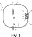
- FIG. 1
- is an overall schematic view illustrating a pneumatic fender of the present invention as viewed in a vertical cross-section.
- FIG. 2
- is a plan view illustrating the area around a mouth piece metal of the present invention illustrated in
FIG. 1 . - FIG. 3
- is an explanatory drawing illustrating an internal structure of the mouth piece metal when viewed in a cross-section taken along A-A of
FIG. 2 . - FIG. 4
- is an explanatory drawing illustrating the area around the mouth piece metal when a through hole is closed as viewed in plain view.
- FIG. 5
- is an explanatory drawing illustrating the internal structure of the mouth piece metal when viewed in a cross-section taken along B-B of
FIG. 4 . - FIG. 6
- is an explanatory drawing illustrating a mouth piece metal of another embodiment of the present invention as viewed in a vertical cross-section.
- FIG. 7
- is an explanatory drawing illustrating a mouth piece metal of yet another embodiment of the present invention as viewed in a vertical cross-section.
- FIG. 8
- is an explanatory drawing illustrating the through hole of
FIG. 7 in a closed state as viewed in a vertical cross-section. - Hereinafter, a pneumatic fender and a mouth piece metal for a pneumatic fender of the present invention will be described with reference to embodiments illustrated in the drawings.
- A pneumatic fender 1 (hereinafter, also fender 1) of the present invention illustrated in
FIG. 1 to FIG. 5 includes afender bladder 2 that is made mainly of rubber and has reinforcing material embedded therein. Thefender bladder 2 is formed with a cylindrical portion 3a and a bowl-likehemispherical portion 3b on each end of the cylindrical portion 3a in the cylinder axial direction connected thereto. - A
mouth piece metal 4 of the present invention is provided on one of thehemispherical portions 3b. Themouth piece metal 4 may also be provided on thehemispherical portion 3b on both sides. Themouth piece metal 4 is a recessed cylinder-like fitting. The opening of themouth piece metal 4 to the surface side may be covered by a lid attached by a bolt or the like. - The
mouth piece metal 4 includes asafety valve 6, acommunication passage 11 that connects acavity 2a of thefender bladder 2 to the outside air, and a bladder open/close valve 11a that opens and closes thecommunication passage 11. Additionally, themouth piece metal 4 includes a receivingchamber 8 that isolates thesafety valve 6 from thecavity 2a, a throughhole 7a formed in a dividingwall 7 constituting the receivingchamber 8, an open/close valve 9 that opens and closes the throughhole 7a, a receivingchamber communication passage 12 that connects acavity 8a of the receivingchamber 8 to the outside air, and a receiving chamber open/close valve 12a that opens and closes the receivingchamber communication passage 12. Themouth piece metal 4 further includes closedposition fixing members 5a and openposition fixing members 5b. - The receiving
chamber 8 is formed extending toward thecavity 2a of thefender bladder 2 from aflat plate 4a on which thesafety valve 6 is attached. In other words, the receivingchamber 8 is formed at a position to the back side of themouth piece metal 4. Thesafety valve 6 is fixed to theflat plate 4a and extends through theflat plate 4a and into thecavity 8a of the receivingchamber 8. Thecommunication passage 11 extends through theflat plate 4a and the receivingchamber 8 and terminates in thecavity 2a. The receivingchamber communication passage 12 extends through theflat plate 4a and terminates in thecavity 8a of the receivingchamber 8. - The
safety valve 6 opens when the pressure reaches a set pressure threshold Pm so that thefender bladder 2 is not damaged when excessively compressed and is closed when the pressure is less than the pressure threshold Pm. In other words, thesafety valve 6 opens to connect thecavity 2a to the outside air when the internal pressure P of thecavity 2a of thefender bladder 2 reaches the pressure threshold Pm. - The open/
close valve 9 includes ashaft 9c and anouter flange 9a and aninner flange 9b fixed to either end of theshaft 9c. Theouter flange 9a and theinner flange 9b are in an opposing configuration. Theshaft 9c extends through theflat plate 4a and can slide freely in the cylinder axial direction of thefender bladder 2. Theinner flange 9b is disposed in thecavity 8a of the receivingchamber 8. Theouter flange 9a is disposed outside of the receivingchamber 8 at a position to the surface side of themouth piece metal 4. The open/close valve 9 can slide freely in the direction in which it moves towards and away from the throughhole 7a. - In
FIGS. 1 to 3 , the throughhole 7a is open with the open/close valve 9 being fixed to theflat plate 4a at a position in which the throughhole 7a is open by the openposition fixing members 5b. The openposition fixing members 5b are disposed outside of the receivingchamber 8 at a position to the surface side of themouth piece metal 4. In this state, the opposing surfaces of theinner flange 9b and theflat plate 4a are in hermetic contact. Aseal material 10c is preferably disposed between the opposing surfaces to increase hermeticity. Theseal material 10c is annular. - In
FIG. 4 andFIG. 5 , the throughhole 7a is closed with the open/close valve 9 being fixed to theflat plate 4a at a position in which the throughhole 7a is closed by the closedposition fixing members 5a. The closedposition fixing members 5a are disposed outside of the receivingchamber 8 at a position to the surface side of themouth piece metal 4. In this state, the opposing surfaces of theinner flange 9b and the dividingwall 7 are in hermetic contact. Theseal material 10c is preferably disposed between the opposing surfaces to increase hermeticity. - Closing position holes 10a and opening position holes 10b are alternately disposed in the
outer flange 9a at intervals in the circumferential direction. The closing position holes 10a and the opening position holes 10b extend through theouter flange 9a in the sliding direction of the open/close valve 9. The closing position holes 10a are simple through holes and the opening position holes 10b are bolt holes. The closedposition fixing members 5a are typical fixing bolts. The openposition fixing members 5b are fixing bolts threaded from the bolt head portion about halfway down in the longitudinal direction. - As illustrated in
FIG. 3 , to keep the throughhole 7a open, the openposition fixing members 5b are screwed into the opening position holes 10b formed in theouter flange 9a, the tips of the openposition fixing members 5b are brought into contact with the surface of theflat plate 4a, and the opposing surfaces of theinner flange 9b and theflat plate 4a are brought into hermetic contact. - As illustrated in
FIG. 5 , to keep the throughhole 7a closed, the closedposition fixing members 5a are inserted in theclosing position holes 10a formed in theouter flange 9a, the tips of the closedposition fixing members 5a are screwed into bolt holes formed in the surface of theflat plate 4a, and theinner flange 9b and the dividing wall 7 (the dividingwall 7 positioned opposing theflat plate 4a) are brought into hermetic contact. - When the
pneumatic fender 1 is used, thecavity 2a is given the predetermined initial internal pressure Pi by being inflated with air or filled with air and fluid (water). In this state, thepneumatic fender 1 is disposed at the place of use such as a wharf. Then, as illustrated inFIG. 3 , the open/close valve 9 is fixed at a position in which the throughhole 7a is open by the openposition fixing members 5b. Accordingly, thecavity 2a of thefender bladder 2 and thecavity 8a of the receivingchamber 8 are connected via the throughhole 7a and thus thecavities - When the
fender bladder 2 is compressed in this state and the internal pressure P of thecavity 2a exceeds the pressure threshold Pm, the internal pressure of thecavity 8a is also exceeded. This causes thesafety valve 6 to open. Thus, when the internal pressure P of thecavity 2a exceeds the pressure threshold Pm by thefender bladder 2 being excessively compressed in such a manner, thesafety valve 6 functions as per convention to connect thecavity 2a to the outside air, thus reducing the internal pressure P of thecavity 2a to the pressure threshold Pm or less. As a result, damage to thefender bladder 2 can be prevented. - As illustrated in
FIG. 5 , when maintenance is performed on thesafety valve 6, the open/close valve 9 is fixed at a position in which the throughhole 7a is closed by the closedposition fixing members 5a. Thesafety valve 6 is isolated from thecavity 2a of thefender bladder 2 by the receivingchamber 8. Accordingly, thesafety valve 6 can be safely detached from themouth piece metal 4 and safely attached to themouth piece metal 4. Thus, thesafety valve 6 can be detached and attached from an in-usepneumatic fender 1 while in use without bringing thepneumatic fender 1 onto land or a marine vessel. - Additionally, with the open/
close valve 9 thus keeping the throughhole 7a closed, by opening the receiving chamber open/close valve 12a and injecting compressed air into thecavity 8a of the receivingchamber 8 via the receivingchamber communication passage 12, the internal pressure of thecavity 8a can be raised to the pressure threshold Pm. In other words, a confirmation test of the valve opening pressure of thesafety valve 6 can be performed on thepneumatic fender 1 while in use. In such a manner, according to the present invention, thesafety valve 6 can be detached and attached and a confirmation test of the valve opening pressure can be performed on thepneumatic fender 1 while in use. As such, the labor and time required for these operations can be greatly reduced, and maintainability can be significantly enhanced. - Another embodiment of the
mouth piece metal 4 is illustrated inFIG. 6 . Thismouth piece metal 4 is provided with openposition fixing members 5c, which are typical fixing bolts, and an openposition fixing member 5d, which is a spacer disposed between theflat plate 4a and theouter flange 9a. As illustrated inFIG. 6 , the openposition fixing member 5d is disposed between theflat plate 4a and theouter flange 9a to keep the throughhole 7a open. Next, the openposition fixing members 5c are screwed into the opening position holes 10b formed in theouter flange 9a, the tips of the openposition fixing members 5c are brought into contact with the surface of the openposition fixing member 5d, which is a spacer, and the opposing surfaces of theinner flange 9b and theflat plate 4a come into hermetic contact. Themouth piece metal 4 of this embodiments allows the length of the fixing bolts, i.e. the openposition fixing members 5c, to be shortened. - Another embodiment of the
mouth piece metal 4 is illustrated inFIG. 7 . Thismouth piece metal 4 is provided with acylindrical guide member 13 that extends through theflat plate 4a. Theguide member 13 includes a first end, with its diameter widened into a flange, fixed to theflat plate 4a. A second end of theguide member 13 extends to a position partway into thecavity 8a of the receivingchamber 8. - A
guide hole 13a formed in theguide member 13 extends in the cylinder axial direction of thefender bladder 2. Theshaft 9c that constitutes the open/close valve 9 is inserted into theguide hole 13a. Theshaft 9c is integrally provided with theouter flange 9a on a first end and theinner flange 9b on a second end. The outer peripheral surface of theshaft 9c and the inner peripheral surface of theguide hole 13a are screwed together, and by rotating theshaft 9c, theinner flange 9b (open/close valve 9) moves toward or away from the throughhole 7a. The inner peripheral surface of theguide hole 13a and the outer peripheral surface of theshaft 9c are in contact with each other with theseal material 10c provided in the space therebetween to provide hermeticity. - Furthermore, a
cover 14 that covers theouter flange 9a is detachably provided on the first end of theguide member 13. Anengagement portion 14a that engages with theouter flange 9a is provided on the inner side of thecover 14. To open the throughhole 7a, thecover 14 is removed from theouter flange 9a and theouter flange 9a together with theshaft 9c are rotated, thus moving theinner flange 9b away from the throughhole 7a. - The
cover 14, which covers theouter flange 9a, prevents any unintentional operation of the open/close valve 9. As illustrated inFIG. 7 , when the throughhole 7a is closed, theinner flange 9b disposed on the second end of theshaft 9c is brought into contact with the surface of the second end of theguide member 13. In this embodiment, themating guide member 13 and theshaft 9c function as the open position fixing member. - As illustrated in
FIG. 8 , to close the throughhole 7a, thecover 14 is removed from theouter flange 9a and theouter flange 9a together with theshaft 9c are rotated (theshaft 9c is rotated in the direction opposite to when opening the throughhole 7a), thus moving theinner flange 9b (open/close valve 9) toward the throughhole 7a. This brings the opposing surfaces of theinner flange 9c and the dividingwall 7 into hermetic contact. As theshaft 9c and theguide hole 13a are screwed together, the open/close valve 9 can be easily fixed at a position in which the throughhole 7a is closed. In this embodiment, themating guide member 13 and theshaft 9c function as the closed position fixing member. - In this embodiment, the stroke length of the open/close valve 9 (distance traveled in the axial direction) required to open and close the through
hole 7a can be changed in accordance with the position of the second end of the guide member 13 (the length theguide member 13 extends into thecavity 8a of the receiving chamber 8). Accordingly, the stroke length of the open/close valve 9 can be easily minimized. -
- 1
- Pneumatic fender
- 2
- Fender bladder
- 2a
- Cavity
- 3a
- Cylindrical portion
- 3b
- Hemispherical portion
- 4
- Mouth piece metal
- 4a
- Flat plate
- 5a
- Closed position fixing member
- 5b, 5c, 5d
- Open position fixing member
- 6
- Safety valve
- 7
- Dividing wall
- 7a
- Through hole
- 8
- Receiving chamber
- 8a
- Cavity
- 9
- Open/close valve
- 9a
- Outer flange
- 9b
- Inner flange
- 9c
- Shaft
- 10a
- Closing position hole
- 10b
- Opening position hole
- 10c
- Seal material
- 11
- Communication passage
- 11a
- Bladder open/close valve
- 12
- Receiving chamber communication passage
- 12a
- Receiving chamber open/close valve
- 13
- Guide member
- 13a
- Guide hole
- 14
- Cover
- 14a
- Engagement portion
Claims (6)
- A pneumatic fender comprising:a fender bladder including a cylindrical portion and bowl-like hemispherical portions connected to each end of the cylindrical portion;a mouth piece metal disposed on at least one of the hemispherical portions, the mouth piece metal including:a safety valve that, upon an internal pressure of a cavity of the fender bladder reaching a pressure threshold, opens to connect the cavity of the fender bladder to outside air and reduce the internal pressure, anda communication passage that connects the cavity of the fender bladder and outside air; anda bladder open/close valve that opens and closes the communication passage; whereinthe mouth piece metal further includes:a receiving chamber that isolates the safety valve from the cavity of the fender bladder,a through hole that connects a cavity of the receiving chamber and the cavity of the fender bladder, the through hole being formed on a dividing wall constituting the receiving chamber,an open/close valve that opens and closes the through hole,a closed position fixing member that fixes the open/close valve at a position in which the through hole is closed,an open position fixing member that fixes the open/close valve at a position in which the through hole is open,a receiving chamber communication passage that connects the cavity of the receiving chamber and outside air, anda receiving chamber open/close valve that opens and closes the receiving chamber communication passage; andthe closed position fixing member and the open position fixing member are disposed outside of the receiving chamber at a position to a surface side of the mouth piece metal.
- The pneumatic fender according to claim 1, wherein
the open/close valve includes:an inner flange disposed in the receiving chamber,an outer flange disposed outside of the receiving chamber at a position to the surface side of the mouth piece metal, anda shaft including ends to which the inner flange and the outer flange are fixed in an opposing manner;the open/close valve is slidable in a direction toward or away from the through hole: and
the open/close valve opens and closes the through hole via the inner flange. - The pneumatic fender according to claim 1 or 2, wherein
a seal material is disposed between opposing surfaces of the open/close valve fixed at a position in which the through hole is closed and the dividing wall approximate to the through hole, and
a seal material is disposed between opposing surfaces of the open/close valve fixed at a position in which the through hole is open and the dividing wall. - A mouth piece metal for a pneumatic fender attachable to a bowl-like hemispherical portion constituting a fender bladder, the mouth piece metal comprising:a safety valve that, upon an internal pressure of a cavity of the fender bladder reaching a pressure threshold, opens to connect the cavity of the fender bladder to outside air and reduce the internal pressure, anda communication passage that connects the cavity of the fender bladder and outside air; anda bladder open/close valve that opens and closes the communication passage; whereinthe mouth piece metal further includes:a receiving chamber that isolates the safety valve from the cavity of the fender bladder,a through hole that connects a cavity of the receiving chamber and the cavity of the fender bladder, the through hole being formed on a dividing wall constituting the receiving chamber,an open/close valve that opens and closes the through hole,a closed position fixing member that fixes the open/close valve at a position in which the through hole is closed,an open position fixing member that fixes the open/close valve at a position in which the through hole is open,a receiving chamber communication passage that connects the cavity of the receiving chamber and outside air, anda receiving chamber open/close valve that opens and closes the receiving chamber communication passage; andthe closed position fixing member and the open position fixing member are disposed outside of the receiving chamber at a position to a surface side of the mouth piece metal.
- The mouth piece metal for a pneumatic fender according to claim 4, wherein the open/close valve includes:an inner flange disposed in the receiving chamber,an outer flange disposed outside of the receiving chamber at a position to the surface side of the mouth piece metal, anda shaft including ends to which the inner flange and the outer flange are fixed in an opposing manner;the open/close valve is slidable in a direction toward or away from the through hole; and
the open/close valve opens and closes the through hole via the inner flange. - The mouth piece metal for a pneumatic fender according to claim 4 or 5, wherein
a seal material is disposed between opposing surfaces of the open/close valve fixed at a position in which the through hole is closed and the dividing wall approximate to the through hole, and
a seal material is disposed between opposing surfaces of the open/close valve fixed at a position in which the through is open and the dividing wall.
Applications Claiming Priority (2)
| Application Number | Priority Date | Filing Date | Title |
|---|---|---|---|
| JP2014071326 | 2014-03-31 | ||
| PCT/JP2015/058951 WO2015151938A1 (en) | 2014-03-31 | 2015-03-24 | Pneumatic fender and pneumatic fender mouthpiece |
Publications (3)
| Publication Number | Publication Date |
|---|---|
| EP3128082A1 true EP3128082A1 (en) | 2017-02-08 |
| EP3128082A4 EP3128082A4 (en) | 2017-11-22 |
| EP3128082B1 EP3128082B1 (en) | 2019-04-24 |
Family
ID=54240265
Family Applications (1)
| Application Number | Title | Priority Date | Filing Date |
|---|---|---|---|
| EP15773754.5A Active EP3128082B1 (en) | 2014-03-31 | 2015-03-24 | Pneumatic fender and pneumatic fender mouthpiece |
Country Status (6)
| Country | Link |
|---|---|
| US (1) | US9816241B2 (en) |
| EP (1) | EP3128082B1 (en) |
| JP (1) | JP6520921B2 (en) |
| KR (1) | KR102352626B1 (en) |
| CN (1) | CN106029986B (en) |
| WO (1) | WO2015151938A1 (en) |
Cited By (1)
| Publication number | Priority date | Publication date | Assignee | Title |
|---|---|---|---|---|
| EP4047134A1 (en) * | 2021-02-23 | 2022-08-24 | Hwaseung Corporation Co., Ltd. | Multi-function safety device for pneumatic fender |
Families Citing this family (5)
| Publication number | Priority date | Publication date | Assignee | Title |
|---|---|---|---|---|
| JP6291968B2 (en) * | 2014-03-31 | 2018-03-14 | 横浜ゴム株式会社 | Pneumatic fenders and air fender fittings |
| US10429647B2 (en) * | 2016-06-10 | 2019-10-01 | Facebook Technologies, Llc | Focus adjusting virtual reality headset |
| KR101882378B1 (en) | 2018-05-17 | 2018-07-26 | (주)화승엑스윌 | Open and closing valve for pneumatic fender |
| JP7180386B2 (en) * | 2019-01-09 | 2022-11-30 | 横浜ゴム株式会社 | pneumatic fender |
| KR102162839B1 (en) | 2020-08-06 | 2020-10-07 | (주)화승엑스윌 | Complex valve for pneumatic fender |
Family Cites Families (19)
| Publication number | Priority date | Publication date | Assignee | Title |
|---|---|---|---|---|
| DE2316503B2 (en) * | 1973-04-03 | 1977-09-15 | Ausscheidung in: 23 65 558 Messerschmitt-Bölkow-Blohm GmbH, 8000 München | BUMPER FOR VEHICLES |
| US4176858A (en) * | 1974-01-04 | 1979-12-04 | Safety Consultants | Energy absorbing bumper system |
| US4099759A (en) * | 1976-05-18 | 1978-07-11 | Safety Consultants | Energy absorbing bumper system |
| JPS6071390A (en) * | 1983-09-28 | 1985-04-23 | Yokohama Rubber Co Ltd:The | Foam-filled fender and manufacturing method thereof |
| JP3786526B2 (en) | 1998-09-09 | 2006-06-14 | 横浜ゴム株式会社 | Airtight testing method and device for pneumatic fenders |
| US6126214A (en) * | 1999-07-26 | 2000-10-03 | Kim; Sun Young | Air bumper |
| JP2002115768A (en) | 2000-10-06 | 2002-04-19 | Asuka Kogyo Kk | Selector valve for safety valve |
| JP4413458B2 (en) | 2001-10-25 | 2010-02-10 | 横浜ゴム株式会社 | Pneumatic fender |
| JP3933438B2 (en) | 2001-10-29 | 2007-06-20 | 横浜ゴム株式会社 | Pneumatic fender |
| CN1285484C (en) * | 2004-01-19 | 2006-11-22 | 孙菊香 | Aerated rubber ball for ship and its production technology |
| CN200985089Y (en) * | 2006-11-28 | 2007-12-05 | 闫海军 | Fill-type rubber fender |
| CN201420256Y (en) * | 2009-05-25 | 2010-03-10 | 青岛天盾橡胶有限公司 | Ultra-large type floating fender |
| CN201588192U (en) * | 2009-10-27 | 2010-09-22 | 钟爱民 | Combined type fender |
| WO2011155265A1 (en) * | 2010-06-11 | 2011-12-15 | 横浜ゴム株式会社 | Pneumatic fender management system |
| JP5077471B1 (en) | 2011-09-30 | 2012-11-21 | 横浜ゴム株式会社 | Sensor container for pneumatic fender and pneumatic fender |
| JP5565434B2 (en) * | 2012-04-27 | 2014-08-06 | 横浜ゴム株式会社 | Pneumatic fender |
| US9428875B2 (en) * | 2012-10-11 | 2016-08-30 | The Yokohama Rubber Co., Ltd. | Pneumatic fender |
| JP6136556B2 (en) * | 2013-05-10 | 2017-05-31 | 横浜ゴム株式会社 | Vertical pneumatic fender |
| JP6291968B2 (en) * | 2014-03-31 | 2018-03-14 | 横浜ゴム株式会社 | Pneumatic fenders and air fender fittings |
-
2015
- 2015-03-24 KR KR1020167022679A patent/KR102352626B1/en active IP Right Grant
- 2015-03-24 WO PCT/JP2015/058951 patent/WO2015151938A1/en active Application Filing
- 2015-03-24 EP EP15773754.5A patent/EP3128082B1/en active Active
- 2015-03-24 JP JP2016511568A patent/JP6520921B2/en active Active
- 2015-03-24 CN CN201580010217.3A patent/CN106029986B/en active Active
- 2015-03-24 US US15/301,190 patent/US9816241B2/en active Active
Cited By (1)
| Publication number | Priority date | Publication date | Assignee | Title |
|---|---|---|---|---|
| EP4047134A1 (en) * | 2021-02-23 | 2022-08-24 | Hwaseung Corporation Co., Ltd. | Multi-function safety device for pneumatic fender |
Also Published As
| Publication number | Publication date |
|---|---|
| KR102352626B1 (en) | 2022-01-18 |
| JP6520921B2 (en) | 2019-05-29 |
| US9816241B2 (en) | 2017-11-14 |
| CN106029986B (en) | 2017-09-22 |
| EP3128082B1 (en) | 2019-04-24 |
| JPWO2015151938A1 (en) | 2017-04-13 |
| WO2015151938A1 (en) | 2015-10-08 |
| KR20160138386A (en) | 2016-12-05 |
| US20170016195A1 (en) | 2017-01-19 |
| EP3128082A4 (en) | 2017-11-22 |
| CN106029986A (en) | 2016-10-12 |
Similar Documents
| Publication | Publication Date | Title |
|---|---|---|
| EP3128082B1 (en) | Pneumatic fender and pneumatic fender mouthpiece | |
| EP3128081B1 (en) | Pneumatic fender and pneumatic fender mouthpiece | |
| CN209668749U (en) | For transport and store liquid and for by the liquid from container traffic to container outside destination system | |
| US9327809B2 (en) | Salvage container and salvaging method | |
| EP2762850A1 (en) | Sensor housing container for pneumatic fender, and pneumatic fender | |
| JP2015151135A (en) | cap | |
| CN205278347U (en) | Dangerous pressure releasing mechanism of airtight pressure vessel | |
| CN109915685A (en) | A kind of wind-tunnel tube body end cap | |
| CN215634926U (en) | Safe explosion-proof pressure vessel | |
| CN209782007U (en) | Wind tunnel pipe end cover | |
| KR100294798B1 (en) | A ship anti - sinking system | |
| KR200492731Y1 (en) | Plug control valve for vacuum operation and vacuum inspection | |
| RU2621930C1 (en) | Drainage device | |
| KR101517721B1 (en) | transmission oil drain structure for automobile | |
| CN211893609U (en) | Piston type submarine cabin door | |
| CN209115754U (en) | A kind of Pull breaking ualve | |
| KR200472374Y1 (en) | Drain water discharging hopper of compressed air container for ship | |
| RU2150561C1 (en) | Locking and sealing device | |
| CN204872544U (en) | Head of carrying machine of fighting is let out and is exploded casing | |
| CN104653546A (en) | Train brake cylinder | |
| KR20140000344U (en) | Assembly for temporary man hole | |
| CA3062933A1 (en) | Device for uncoupling a plug from a pulling head | |
| CN103968122A (en) | Quick-opening valve adopting single blind tube structure | |
| ITMI990113U1 (en) | PROTECTIVE OIL MILK CONTAINER FOR ENGINES | |
| CN104747767A (en) | Venting screw and hydraulic brake |
Legal Events
| Date | Code | Title | Description |
|---|---|---|---|
| STAA | Information on the status of an ep patent application or granted ep patent |
Free format text: STATUS: THE INTERNATIONAL PUBLICATION HAS BEEN MADE |
|
| PUAI | Public reference made under article 153(3) epc to a published international application that has entered the european phase |
Free format text: ORIGINAL CODE: 0009012 |
|
| STAA | Information on the status of an ep patent application or granted ep patent |
Free format text: STATUS: REQUEST FOR EXAMINATION WAS MADE |
|
| 17P | Request for examination filed |
Effective date: 20161031 |
|
| AK | Designated contracting states |
Kind code of ref document: A1 Designated state(s): AL AT BE BG CH CY CZ DE DK EE ES FI FR GB GR HR HU IE IS IT LI LT LU LV MC MK MT NL NO PL PT RO RS SE SI SK SM TR |
|
| AX | Request for extension of the european patent |
Extension state: BA ME |
|
| DAV | Request for validation of the european patent (deleted) | ||
| DAX | Request for extension of the european patent (deleted) | ||
| A4 | Supplementary search report drawn up and despatched |
Effective date: 20171023 |
|
| RIC1 | Information provided on ipc code assigned before grant |
Ipc: E02B 3/26 20060101AFI20171017BHEP Ipc: B63B 59/02 20060101ALI20171017BHEP |
|
| GRAP | Despatch of communication of intention to grant a patent |
Free format text: ORIGINAL CODE: EPIDOSNIGR1 |
|
| STAA | Information on the status of an ep patent application or granted ep patent |
Free format text: STATUS: GRANT OF PATENT IS INTENDED |
|
| INTG | Intention to grant announced |
Effective date: 20181207 |
|
| GRAS | Grant fee paid |
Free format text: ORIGINAL CODE: EPIDOSNIGR3 |
|
| GRAA | (expected) grant |
Free format text: ORIGINAL CODE: 0009210 |
|
| STAA | Information on the status of an ep patent application or granted ep patent |
Free format text: STATUS: THE PATENT HAS BEEN GRANTED |
|
| AK | Designated contracting states |
Kind code of ref document: B1 Designated state(s): AL AT BE BG CH CY CZ DE DK EE ES FI FR GB GR HR HU IE IS IT LI LT LU LV MC MK MT NL NO PL PT RO RS SE SI SK SM TR |
|
| REG | Reference to a national code |
Ref country code: GB Ref legal event code: FG4D |
|
| REG | Reference to a national code |
Ref country code: CH Ref legal event code: EP |
|
| REG | Reference to a national code |
Ref country code: AT Ref legal event code: REF Ref document number: 1124316 Country of ref document: AT Kind code of ref document: T Effective date: 20190515 Ref country code: IE Ref legal event code: FG4D |
|
| REG | Reference to a national code |
Ref country code: DE Ref legal event code: R096 Ref document number: 602015028950 Country of ref document: DE |
|
| REG | Reference to a national code |
Ref country code: NL Ref legal event code: FP |
|
| REG | Reference to a national code |
Ref country code: SE Ref legal event code: TRGR |
|
| REG | Reference to a national code |
Ref country code: LT Ref legal event code: MG4D |
|
| REG | Reference to a national code |
Ref country code: NO Ref legal event code: T2 Effective date: 20190424 |
|
| PG25 | Lapsed in a contracting state [announced via postgrant information from national office to epo] |
Ref country code: HR Free format text: LAPSE BECAUSE OF FAILURE TO SUBMIT A TRANSLATION OF THE DESCRIPTION OR TO PAY THE FEE WITHIN THE PRESCRIBED TIME-LIMIT Effective date: 20190424 Ref country code: LT Free format text: LAPSE BECAUSE OF FAILURE TO SUBMIT A TRANSLATION OF THE DESCRIPTION OR TO PAY THE FEE WITHIN THE PRESCRIBED TIME-LIMIT Effective date: 20190424 Ref country code: ES Free format text: LAPSE BECAUSE OF FAILURE TO SUBMIT A TRANSLATION OF THE DESCRIPTION OR TO PAY THE FEE WITHIN THE PRESCRIBED TIME-LIMIT Effective date: 20190424 Ref country code: AL Free format text: LAPSE BECAUSE OF FAILURE TO SUBMIT A TRANSLATION OF THE DESCRIPTION OR TO PAY THE FEE WITHIN THE PRESCRIBED TIME-LIMIT Effective date: 20190424 Ref country code: PT Free format text: LAPSE BECAUSE OF FAILURE TO SUBMIT A TRANSLATION OF THE DESCRIPTION OR TO PAY THE FEE WITHIN THE PRESCRIBED TIME-LIMIT Effective date: 20190824 Ref country code: FI Free format text: LAPSE BECAUSE OF FAILURE TO SUBMIT A TRANSLATION OF THE DESCRIPTION OR TO PAY THE FEE WITHIN THE PRESCRIBED TIME-LIMIT Effective date: 20190424 |
|
| PG25 | Lapsed in a contracting state [announced via postgrant information from national office to epo] |
Ref country code: BG Free format text: LAPSE BECAUSE OF FAILURE TO SUBMIT A TRANSLATION OF THE DESCRIPTION OR TO PAY THE FEE WITHIN THE PRESCRIBED TIME-LIMIT Effective date: 20190724 Ref country code: GR Free format text: LAPSE BECAUSE OF FAILURE TO SUBMIT A TRANSLATION OF THE DESCRIPTION OR TO PAY THE FEE WITHIN THE PRESCRIBED TIME-LIMIT Effective date: 20190725 Ref country code: LV Free format text: LAPSE BECAUSE OF FAILURE TO SUBMIT A TRANSLATION OF THE DESCRIPTION OR TO PAY THE FEE WITHIN THE PRESCRIBED TIME-LIMIT Effective date: 20190424 Ref country code: PL Free format text: LAPSE BECAUSE OF FAILURE TO SUBMIT A TRANSLATION OF THE DESCRIPTION OR TO PAY THE FEE WITHIN THE PRESCRIBED TIME-LIMIT Effective date: 20190424 Ref country code: RS Free format text: LAPSE BECAUSE OF FAILURE TO SUBMIT A TRANSLATION OF THE DESCRIPTION OR TO PAY THE FEE WITHIN THE PRESCRIBED TIME-LIMIT Effective date: 20190424 |
|
| REG | Reference to a national code |
Ref country code: AT Ref legal event code: MK05 Ref document number: 1124316 Country of ref document: AT Kind code of ref document: T Effective date: 20190424 |
|
| PG25 | Lapsed in a contracting state [announced via postgrant information from national office to epo] |
Ref country code: IS Free format text: LAPSE BECAUSE OF FAILURE TO SUBMIT A TRANSLATION OF THE DESCRIPTION OR TO PAY THE FEE WITHIN THE PRESCRIBED TIME-LIMIT Effective date: 20190824 |
|
| REG | Reference to a national code |
Ref country code: DE Ref legal event code: R097 Ref document number: 602015028950 Country of ref document: DE |
|
| PG25 | Lapsed in a contracting state [announced via postgrant information from national office to epo] |
Ref country code: SK Free format text: LAPSE BECAUSE OF FAILURE TO SUBMIT A TRANSLATION OF THE DESCRIPTION OR TO PAY THE FEE WITHIN THE PRESCRIBED TIME-LIMIT Effective date: 20190424 Ref country code: RO Free format text: LAPSE BECAUSE OF FAILURE TO SUBMIT A TRANSLATION OF THE DESCRIPTION OR TO PAY THE FEE WITHIN THE PRESCRIBED TIME-LIMIT Effective date: 20190424 Ref country code: CZ Free format text: LAPSE BECAUSE OF FAILURE TO SUBMIT A TRANSLATION OF THE DESCRIPTION OR TO PAY THE FEE WITHIN THE PRESCRIBED TIME-LIMIT Effective date: 20190424 Ref country code: DK Free format text: LAPSE BECAUSE OF FAILURE TO SUBMIT A TRANSLATION OF THE DESCRIPTION OR TO PAY THE FEE WITHIN THE PRESCRIBED TIME-LIMIT Effective date: 20190424 Ref country code: EE Free format text: LAPSE BECAUSE OF FAILURE TO SUBMIT A TRANSLATION OF THE DESCRIPTION OR TO PAY THE FEE WITHIN THE PRESCRIBED TIME-LIMIT Effective date: 20190424 Ref country code: AT Free format text: LAPSE BECAUSE OF FAILURE TO SUBMIT A TRANSLATION OF THE DESCRIPTION OR TO PAY THE FEE WITHIN THE PRESCRIBED TIME-LIMIT Effective date: 20190424 |
|
| PG25 | Lapsed in a contracting state [announced via postgrant information from national office to epo] |
Ref country code: SM Free format text: LAPSE BECAUSE OF FAILURE TO SUBMIT A TRANSLATION OF THE DESCRIPTION OR TO PAY THE FEE WITHIN THE PRESCRIBED TIME-LIMIT Effective date: 20190424 |
|
| PLBE | No opposition filed within time limit |
Free format text: ORIGINAL CODE: 0009261 |
|
| STAA | Information on the status of an ep patent application or granted ep patent |
Free format text: STATUS: NO OPPOSITION FILED WITHIN TIME LIMIT |
|
| PG25 | Lapsed in a contracting state [announced via postgrant information from national office to epo] |
Ref country code: TR Free format text: LAPSE BECAUSE OF FAILURE TO SUBMIT A TRANSLATION OF THE DESCRIPTION OR TO PAY THE FEE WITHIN THE PRESCRIBED TIME-LIMIT Effective date: 20190424 |
|
| 26N | No opposition filed |
Effective date: 20200127 |
|
| PG25 | Lapsed in a contracting state [announced via postgrant information from national office to epo] |
Ref country code: SI Free format text: LAPSE BECAUSE OF FAILURE TO SUBMIT A TRANSLATION OF THE DESCRIPTION OR TO PAY THE FEE WITHIN THE PRESCRIBED TIME-LIMIT Effective date: 20190424 |
|
| REG | Reference to a national code |
Ref country code: DE Ref legal event code: R119 Ref document number: 602015028950 Country of ref document: DE |
|
| PG25 | Lapsed in a contracting state [announced via postgrant information from national office to epo] |
Ref country code: MC Free format text: LAPSE BECAUSE OF FAILURE TO SUBMIT A TRANSLATION OF THE DESCRIPTION OR TO PAY THE FEE WITHIN THE PRESCRIBED TIME-LIMIT Effective date: 20190424 |
|
| REG | Reference to a national code |
Ref country code: CH Ref legal event code: PL |
|
| REG | Reference to a national code |
Ref country code: BE Ref legal event code: MM Effective date: 20200331 |
|
| PG25 | Lapsed in a contracting state [announced via postgrant information from national office to epo] |
Ref country code: LU Free format text: LAPSE BECAUSE OF NON-PAYMENT OF DUE FEES Effective date: 20200324 |
|
| PG25 | Lapsed in a contracting state [announced via postgrant information from national office to epo] |
Ref country code: DE Free format text: LAPSE BECAUSE OF NON-PAYMENT OF DUE FEES Effective date: 20201001 Ref country code: LI Free format text: LAPSE BECAUSE OF NON-PAYMENT OF DUE FEES Effective date: 20200331 Ref country code: IE Free format text: LAPSE BECAUSE OF NON-PAYMENT OF DUE FEES Effective date: 20200324 Ref country code: CH Free format text: LAPSE BECAUSE OF NON-PAYMENT OF DUE FEES Effective date: 20200331 |
|
| PG25 | Lapsed in a contracting state [announced via postgrant information from national office to epo] |
Ref country code: BE Free format text: LAPSE BECAUSE OF NON-PAYMENT OF DUE FEES Effective date: 20200331 |
|
| PG25 | Lapsed in a contracting state [announced via postgrant information from national office to epo] |
Ref country code: MT Free format text: LAPSE BECAUSE OF FAILURE TO SUBMIT A TRANSLATION OF THE DESCRIPTION OR TO PAY THE FEE WITHIN THE PRESCRIBED TIME-LIMIT Effective date: 20190424 Ref country code: CY Free format text: LAPSE BECAUSE OF FAILURE TO SUBMIT A TRANSLATION OF THE DESCRIPTION OR TO PAY THE FEE WITHIN THE PRESCRIBED TIME-LIMIT Effective date: 20190424 |
|
| PG25 | Lapsed in a contracting state [announced via postgrant information from national office to epo] |
Ref country code: MK Free format text: LAPSE BECAUSE OF FAILURE TO SUBMIT A TRANSLATION OF THE DESCRIPTION OR TO PAY THE FEE WITHIN THE PRESCRIBED TIME-LIMIT Effective date: 20190424 |
|
| P01 | Opt-out of the competence of the unified patent court (upc) registered |
Effective date: 20230512 |
|
| PGFP | Annual fee paid to national office [announced via postgrant information from national office to epo] |
Ref country code: NL Payment date: 20240214 Year of fee payment: 10 |
|
| PGFP | Annual fee paid to national office [announced via postgrant information from national office to epo] |
Ref country code: GB Payment date: 20240201 Year of fee payment: 10 |
|
| PGFP | Annual fee paid to national office [announced via postgrant information from national office to epo] |
Ref country code: SE Payment date: 20240212 Year of fee payment: 10 Ref country code: NO Payment date: 20240222 Year of fee payment: 10 Ref country code: IT Payment date: 20240212 Year of fee payment: 10 Ref country code: FR Payment date: 20240308 Year of fee payment: 10 |