EP3127769A1 - System and approach for dynamic vehicle speed optimization - Google Patents
System and approach for dynamic vehicle speed optimization Download PDFInfo
- Publication number
- EP3127769A1 EP3127769A1 EP16181570.9A EP16181570A EP3127769A1 EP 3127769 A1 EP3127769 A1 EP 3127769A1 EP 16181570 A EP16181570 A EP 16181570A EP 3127769 A1 EP3127769 A1 EP 3127769A1
- Authority
- EP
- European Patent Office
- Prior art keywords
- vehicle
- energy
- speed
- controller
- over
- Prior art date
- Legal status (The legal status is an assumption and is not a legal conclusion. Google has not performed a legal analysis and makes no representation as to the accuracy of the status listed.)
- Granted
Links
Images


Classifications
-
- B—PERFORMING OPERATIONS; TRANSPORTING
- B60—VEHICLES IN GENERAL
- B60W—CONJOINT CONTROL OF VEHICLE SUB-UNITS OF DIFFERENT TYPE OR DIFFERENT FUNCTION; CONTROL SYSTEMS SPECIALLY ADAPTED FOR HYBRID VEHICLES; ROAD VEHICLE DRIVE CONTROL SYSTEMS FOR PURPOSES NOT RELATED TO THE CONTROL OF A PARTICULAR SUB-UNIT
- B60W30/00—Purposes of road vehicle drive control systems not related to the control of a particular sub-unit, e.g. of systems using conjoint control of vehicle sub-units
- B60W30/18—Propelling the vehicle
-
- B—PERFORMING OPERATIONS; TRANSPORTING
- B60—VEHICLES IN GENERAL
- B60K—ARRANGEMENT OR MOUNTING OF PROPULSION UNITS OR OF TRANSMISSIONS IN VEHICLES; ARRANGEMENT OR MOUNTING OF PLURAL DIVERSE PRIME-MOVERS IN VEHICLES; AUXILIARY DRIVES FOR VEHICLES; INSTRUMENTATION OR DASHBOARDS FOR VEHICLES; ARRANGEMENTS IN CONNECTION WITH COOLING, AIR INTAKE, GAS EXHAUST OR FUEL SUPPLY OF PROPULSION UNITS IN VEHICLES
- B60K31/00—Vehicle fittings, acting on a single sub-unit only, for automatically controlling vehicle speed, i.e. preventing speed from exceeding an arbitrarily established velocity or maintaining speed at a particular velocity, as selected by the vehicle operator
- B60K31/0008—Vehicle fittings, acting on a single sub-unit only, for automatically controlling vehicle speed, i.e. preventing speed from exceeding an arbitrarily established velocity or maintaining speed at a particular velocity, as selected by the vehicle operator including means for detecting potential obstacles in vehicle path
-
- B—PERFORMING OPERATIONS; TRANSPORTING
- B60—VEHICLES IN GENERAL
- B60W—CONJOINT CONTROL OF VEHICLE SUB-UNITS OF DIFFERENT TYPE OR DIFFERENT FUNCTION; CONTROL SYSTEMS SPECIALLY ADAPTED FOR HYBRID VEHICLES; ROAD VEHICLE DRIVE CONTROL SYSTEMS FOR PURPOSES NOT RELATED TO THE CONTROL OF A PARTICULAR SUB-UNIT
- B60W10/00—Conjoint control of vehicle sub-units of different type or different function
- B60W10/04—Conjoint control of vehicle sub-units of different type or different function including control of propulsion units
-
- B—PERFORMING OPERATIONS; TRANSPORTING
- B60—VEHICLES IN GENERAL
- B60W—CONJOINT CONTROL OF VEHICLE SUB-UNITS OF DIFFERENT TYPE OR DIFFERENT FUNCTION; CONTROL SYSTEMS SPECIALLY ADAPTED FOR HYBRID VEHICLES; ROAD VEHICLE DRIVE CONTROL SYSTEMS FOR PURPOSES NOT RELATED TO THE CONTROL OF A PARTICULAR SUB-UNIT
- B60W20/00—Control systems specially adapted for hybrid vehicles
- B60W20/10—Controlling the power contribution of each of the prime movers to meet required power demand
- B60W20/11—Controlling the power contribution of each of the prime movers to meet required power demand using model predictive control [MPC] strategies, i.e. control methods based on models predicting performance
-
- B—PERFORMING OPERATIONS; TRANSPORTING
- B60—VEHICLES IN GENERAL
- B60W—CONJOINT CONTROL OF VEHICLE SUB-UNITS OF DIFFERENT TYPE OR DIFFERENT FUNCTION; CONTROL SYSTEMS SPECIALLY ADAPTED FOR HYBRID VEHICLES; ROAD VEHICLE DRIVE CONTROL SYSTEMS FOR PURPOSES NOT RELATED TO THE CONTROL OF A PARTICULAR SUB-UNIT
- B60W30/00—Purposes of road vehicle drive control systems not related to the control of a particular sub-unit, e.g. of systems using conjoint control of vehicle sub-units
- B60W30/14—Adaptive cruise control
- B60W30/143—Speed control
-
- B—PERFORMING OPERATIONS; TRANSPORTING
- B60—VEHICLES IN GENERAL
- B60W—CONJOINT CONTROL OF VEHICLE SUB-UNITS OF DIFFERENT TYPE OR DIFFERENT FUNCTION; CONTROL SYSTEMS SPECIALLY ADAPTED FOR HYBRID VEHICLES; ROAD VEHICLE DRIVE CONTROL SYSTEMS FOR PURPOSES NOT RELATED TO THE CONTROL OF A PARTICULAR SUB-UNIT
- B60W40/00—Estimation or calculation of non-directly measurable driving parameters for road vehicle drive control systems not related to the control of a particular sub unit, e.g. by using mathematical models
- B60W40/02—Estimation or calculation of non-directly measurable driving parameters for road vehicle drive control systems not related to the control of a particular sub unit, e.g. by using mathematical models related to ambient conditions
- B60W40/06—Road conditions
- B60W40/076—Slope angle of the road
-
- B—PERFORMING OPERATIONS; TRANSPORTING
- B60—VEHICLES IN GENERAL
- B60W—CONJOINT CONTROL OF VEHICLE SUB-UNITS OF DIFFERENT TYPE OR DIFFERENT FUNCTION; CONTROL SYSTEMS SPECIALLY ADAPTED FOR HYBRID VEHICLES; ROAD VEHICLE DRIVE CONTROL SYSTEMS FOR PURPOSES NOT RELATED TO THE CONTROL OF A PARTICULAR SUB-UNIT
- B60W40/00—Estimation or calculation of non-directly measurable driving parameters for road vehicle drive control systems not related to the control of a particular sub unit, e.g. by using mathematical models
- B60W40/12—Estimation or calculation of non-directly measurable driving parameters for road vehicle drive control systems not related to the control of a particular sub unit, e.g. by using mathematical models related to parameters of the vehicle itself, e.g. tyre models
- B60W40/13—Load or weight
-
- B—PERFORMING OPERATIONS; TRANSPORTING
- B60—VEHICLES IN GENERAL
- B60W—CONJOINT CONTROL OF VEHICLE SUB-UNITS OF DIFFERENT TYPE OR DIFFERENT FUNCTION; CONTROL SYSTEMS SPECIALLY ADAPTED FOR HYBRID VEHICLES; ROAD VEHICLE DRIVE CONTROL SYSTEMS FOR PURPOSES NOT RELATED TO THE CONTROL OF A PARTICULAR SUB-UNIT
- B60W50/00—Details of control systems for road vehicle drive control not related to the control of a particular sub-unit, e.g. process diagnostic or vehicle driver interfaces
- B60W50/0097—Predicting future conditions
-
- G—PHYSICS
- G05—CONTROLLING; REGULATING
- G05D—SYSTEMS FOR CONTROLLING OR REGULATING NON-ELECTRIC VARIABLES
- G05D1/00—Control of position, course, altitude or attitude of land, water, air or space vehicles, e.g. using automatic pilots
- G05D1/0005—Control of position, course, altitude or attitude of land, water, air or space vehicles, e.g. using automatic pilots with arrangements to save energy
-
- B—PERFORMING OPERATIONS; TRANSPORTING
- B60—VEHICLES IN GENERAL
- B60W—CONJOINT CONTROL OF VEHICLE SUB-UNITS OF DIFFERENT TYPE OR DIFFERENT FUNCTION; CONTROL SYSTEMS SPECIALLY ADAPTED FOR HYBRID VEHICLES; ROAD VEHICLE DRIVE CONTROL SYSTEMS FOR PURPOSES NOT RELATED TO THE CONTROL OF A PARTICULAR SUB-UNIT
- B60W50/00—Details of control systems for road vehicle drive control not related to the control of a particular sub-unit, e.g. process diagnostic or vehicle driver interfaces
- B60W2050/0001—Details of the control system
- B60W2050/0019—Control system elements or transfer functions
- B60W2050/0028—Mathematical models, e.g. for simulation
-
- B—PERFORMING OPERATIONS; TRANSPORTING
- B60—VEHICLES IN GENERAL
- B60W—CONJOINT CONTROL OF VEHICLE SUB-UNITS OF DIFFERENT TYPE OR DIFFERENT FUNCTION; CONTROL SYSTEMS SPECIALLY ADAPTED FOR HYBRID VEHICLES; ROAD VEHICLE DRIVE CONTROL SYSTEMS FOR PURPOSES NOT RELATED TO THE CONTROL OF A PARTICULAR SUB-UNIT
- B60W2510/00—Input parameters relating to a particular sub-units
- B60W2510/06—Combustion engines, Gas turbines
- B60W2510/0614—Position of fuel or air injector
- B60W2510/0623—Fuel flow rate
-
- B—PERFORMING OPERATIONS; TRANSPORTING
- B60—VEHICLES IN GENERAL
- B60W—CONJOINT CONTROL OF VEHICLE SUB-UNITS OF DIFFERENT TYPE OR DIFFERENT FUNCTION; CONTROL SYSTEMS SPECIALLY ADAPTED FOR HYBRID VEHICLES; ROAD VEHICLE DRIVE CONTROL SYSTEMS FOR PURPOSES NOT RELATED TO THE CONTROL OF A PARTICULAR SUB-UNIT
- B60W2530/00—Input parameters relating to vehicle conditions or values, not covered by groups B60W2510/00 or B60W2520/00
- B60W2530/16—Driving resistance
-
- B—PERFORMING OPERATIONS; TRANSPORTING
- B60—VEHICLES IN GENERAL
- B60W—CONJOINT CONTROL OF VEHICLE SUB-UNITS OF DIFFERENT TYPE OR DIFFERENT FUNCTION; CONTROL SYSTEMS SPECIALLY ADAPTED FOR HYBRID VEHICLES; ROAD VEHICLE DRIVE CONTROL SYSTEMS FOR PURPOSES NOT RELATED TO THE CONTROL OF A PARTICULAR SUB-UNIT
- B60W2552/00—Input parameters relating to infrastructure
- B60W2552/15—Road slope, i.e. the inclination of a road segment in the longitudinal direction
-
- B—PERFORMING OPERATIONS; TRANSPORTING
- B60—VEHICLES IN GENERAL
- B60W—CONJOINT CONTROL OF VEHICLE SUB-UNITS OF DIFFERENT TYPE OR DIFFERENT FUNCTION; CONTROL SYSTEMS SPECIALLY ADAPTED FOR HYBRID VEHICLES; ROAD VEHICLE DRIVE CONTROL SYSTEMS FOR PURPOSES NOT RELATED TO THE CONTROL OF A PARTICULAR SUB-UNIT
- B60W2552/00—Input parameters relating to infrastructure
- B60W2552/20—Road profile, i.e. the change in elevation or curvature of a plurality of continuous road segments
-
- B—PERFORMING OPERATIONS; TRANSPORTING
- B60—VEHICLES IN GENERAL
- B60W—CONJOINT CONTROL OF VEHICLE SUB-UNITS OF DIFFERENT TYPE OR DIFFERENT FUNCTION; CONTROL SYSTEMS SPECIALLY ADAPTED FOR HYBRID VEHICLES; ROAD VEHICLE DRIVE CONTROL SYSTEMS FOR PURPOSES NOT RELATED TO THE CONTROL OF A PARTICULAR SUB-UNIT
- B60W2555/00—Input parameters relating to exterior conditions, not covered by groups B60W2552/00, B60W2554/00
- B60W2555/60—Traffic rules, e.g. speed limits or right of way
-
- B—PERFORMING OPERATIONS; TRANSPORTING
- B60—VEHICLES IN GENERAL
- B60W—CONJOINT CONTROL OF VEHICLE SUB-UNITS OF DIFFERENT TYPE OR DIFFERENT FUNCTION; CONTROL SYSTEMS SPECIALLY ADAPTED FOR HYBRID VEHICLES; ROAD VEHICLE DRIVE CONTROL SYSTEMS FOR PURPOSES NOT RELATED TO THE CONTROL OF A PARTICULAR SUB-UNIT
- B60W2710/00—Output or target parameters relating to a particular sub-units
- B60W2710/06—Combustion engines, Gas turbines
-
- B—PERFORMING OPERATIONS; TRANSPORTING
- B60—VEHICLES IN GENERAL
- B60W—CONJOINT CONTROL OF VEHICLE SUB-UNITS OF DIFFERENT TYPE OR DIFFERENT FUNCTION; CONTROL SYSTEMS SPECIALLY ADAPTED FOR HYBRID VEHICLES; ROAD VEHICLE DRIVE CONTROL SYSTEMS FOR PURPOSES NOT RELATED TO THE CONTROL OF A PARTICULAR SUB-UNIT
- B60W2710/00—Output or target parameters relating to a particular sub-units
- B60W2710/08—Electric propulsion units
-
- B—PERFORMING OPERATIONS; TRANSPORTING
- B60—VEHICLES IN GENERAL
- B60W—CONJOINT CONTROL OF VEHICLE SUB-UNITS OF DIFFERENT TYPE OR DIFFERENT FUNCTION; CONTROL SYSTEMS SPECIALLY ADAPTED FOR HYBRID VEHICLES; ROAD VEHICLE DRIVE CONTROL SYSTEMS FOR PURPOSES NOT RELATED TO THE CONTROL OF A PARTICULAR SUB-UNIT
- B60W2720/00—Output or target parameters relating to overall vehicle dynamics
- B60W2720/10—Longitudinal speed
-
- Y—GENERAL TAGGING OF NEW TECHNOLOGICAL DEVELOPMENTS; GENERAL TAGGING OF CROSS-SECTIONAL TECHNOLOGIES SPANNING OVER SEVERAL SECTIONS OF THE IPC; TECHNICAL SUBJECTS COVERED BY FORMER USPC CROSS-REFERENCE ART COLLECTIONS [XRACs] AND DIGESTS
- Y02—TECHNOLOGIES OR APPLICATIONS FOR MITIGATION OR ADAPTATION AGAINST CLIMATE CHANGE
- Y02T—CLIMATE CHANGE MITIGATION TECHNOLOGIES RELATED TO TRANSPORTATION
- Y02T10/00—Road transport of goods or passengers
- Y02T10/10—Internal combustion engine [ICE] based vehicles
- Y02T10/40—Engine management systems
-
- Y—GENERAL TAGGING OF NEW TECHNOLOGICAL DEVELOPMENTS; GENERAL TAGGING OF CROSS-SECTIONAL TECHNOLOGIES SPANNING OVER SEVERAL SECTIONS OF THE IPC; TECHNICAL SUBJECTS COVERED BY FORMER USPC CROSS-REFERENCE ART COLLECTIONS [XRACs] AND DIGESTS
- Y02—TECHNOLOGIES OR APPLICATIONS FOR MITIGATION OR ADAPTATION AGAINST CLIMATE CHANGE
- Y02T—CLIMATE CHANGE MITIGATION TECHNOLOGIES RELATED TO TRANSPORTATION
- Y02T10/00—Road transport of goods or passengers
- Y02T10/80—Technologies aiming to reduce greenhouse gasses emissions common to all road transportation technologies
- Y02T10/84—Data processing systems or methods, management, administration
Definitions
- the present disclosure pertains to vehicle systems, and particularly to controlling speeds of a vehicle. More particularly, the disclosure pertains to performance improvement in speed control systems.
- a vehicle system may include a vehicle, a propulsion device, such as a combustion engine or an electric motor, and a controller in communication with the propulsion device.
- the propulsion device may at least partially power the vehicle and may consume primary energy, such as fuel or electric energy stored in a battery.
- the controller may control the propulsion device. In some cases, the controller may control the propulsion device according to a target speed of the vehicle.
- the controller may include a model of energy balances of the vehicle and may use the model to estimate energy losses over a travel horizon of the vehicle.
- the model estimating energy losses over a travel horizon of the vehicle may take into account one or more measures of parameters related to the travel horizon, where the parameters related to the travel horizon may include one or more of a mass of the vehicle and a road grade of a road on which the vehicle is positioned over the travel horizon, and one or more other parameters may be utilized.
- the controller may use the estimated energy losses over the travel horizon of the vehicle to optimize a cost function over the travel horizon and set an actual speed for the vehicle.
- the present system and approach may incorporate one or more processors, computers, controllers, user interfaces, wireless and/or wire connections, and/or the like, wherever desired.
- Typical operation of a vehicle may have the goal to transport people or goods from place A to place B, along a predetermined route.
- An operator of the vehicle and/or potential passengers of the vehicle hereafter referred to as users, may have certain expectations and requirements connected to transportation from place A to place B.
- users may have expectations and/or requirements that have to do with comfort of driving and/or riding, the duration of the transport from place A to place B, fuel required to reach place B from place A, and/or one or more other expectations or requirements.
- True user expectations and/or requirements may trade-off different individual expectations and/or requirements of a user over a horizon, which may exceed many travel horizons that are practical in context of solving an optimization problem over the travel horizon, and which may possibly even exceed a route of a trip from place A to place B.
- the expectations and requirements of users may be turned into an optimization issue to maximize overall satisfaction of users of a vehicle.
- a comfort of driving and/or riding expectation and/or requirement may be expressed in terms of acceleration and/or change of acceleration of the vehicle.
- a fuel consumption expectation and/or requirement one or more different terms may be used.
- a scaled, distance-specific fuel consumption model may be used, but this is not always the case.
- a scaled, distance-specific fuel consumption related optimization variable used in a cost function may be minimized by an optimizer and/or controller of a vehicle.
- a scaled, distance-specific fuel consumption optimization model may not be desirable for use in an optimization problem that does not solve the optimization problem for the complete remaining route from place A to place B, but rather only for a limited future horizon representing a part of the remaining route to place B.
- Such limited horizon optimizers that, amongst others minimize the fuel consumption and that do not solve the optimization problem for the entire remaining trip from place A to place B may be expected to become a common solution for real-world implementable vehicle-speed control solutions in next generation vehicle systems.
- optimizing a distance-specific fuel consumption parameter for a travel horizon may be related to the fuel mass consumed over a travel horizon by a change in altitude or change in vehicle speed over that travel horizon.
- a fuel mass flow signal (measured or estimated from propulsion-device operation) may correspond to a flow of chemical energy (e.g., power) invested for propulsion of the vehicle.
- a portion of this chemical energy flow invested may not necessarily be optimizeable because it is outside of the scope of the optimization problem.
- a part of the chemical energy flow invested may be recollected completely or at least partially at the end of the interval and thus may not be necessarily consumed in an energetic sense.
- fuel consumed may not necessarily be proportional to energy consumed in a context of a user's expectations and/or requirements. This may be so because a part of fuel energy consumed by a propulsion device (e.g., a combustion engine, an electric motor, or other propulsion device) of a vehicle might still be available in a form of an increased potential or kinetic energy in the vehicle at the end of the horizon with respect to the initial level of potential or kinetic energy.
- a propulsion device e.g., a combustion engine, an electric motor, or other propulsion device
- This difference in fuel consumption may lead to a bias of the user-defined trade-off between a user's true expectations and/or requirements if the vehicle energy is ignored in the optimization problem.
- a fuel-cost over a travel horizon may appear to be higher resulting in over-weighting of the fuel consumption related expectations and/or requirements.
- the fuel consumption related expectations and/or requirements may be under-weighted.
- potential energy of a vehicle with a given mass may change as the vehicle travels. As long as the horizon of at least a portion along a route from place A to place B and/or the vehicle mass are not changed, a potential energy of the vehicle connected to differences in altitude over the horizon may have to be invested and it does not necessarily matter if potential energy is invested with high or lower power (e.g., high or low speed). Further, as speed (e.g., kinetic energy) may change over a travel horizon, the fuel mass flow may be higher during phases of acceleration than in phases of constant speed (e.g., zero acceleration) because additional chemical energy flow may need to be invested to accelerate the vehicle.
- high or lower power e.g., high or low speed
- a more appropriate optimization approach may be used such that true user expectations and/or requirements may be met when optimizing a vehicle speed trajectory from place A to place B.
- a more appropriate optimization approach that addresses the bias issue may include an optimization approach that uses a cost function taking into consideration energy losses of a vehicle over a travel horizon by subtracting the fuel-energy parameters required for a change in kinetic energy of the vehicle and for the change in potential energy of the vehicle from the fuel energy invested over a travel horizon.
- the cost function of the optimization problem may consider energy losses (e.g., a part of the fuel mass flow that is being consumed by losses, such as friction, drag, and so forth).
- energy losses e.g., a part of the fuel mass flow that is being consumed by losses, such as friction, drag, and so forth.
- a fuel mass flow signal that may typically be used as an input for an optimization problem may be corrected by subtracting the rate of potential energy change of the vehicle and by subtracting the rate of kinetic energy change of the vehicle, both corrected by a lower heating value of fuel in the vehicle.
- a vehicle controller may utilize a mathematical model of energy flows and/or balances of the vehicle. Further, expectations and/or requirements of users and the relative importance of each of the expectations and/or requirements may be considered in the optimization approach. Some of the expectations and/or requirements of users may include, but are not limited to, limits on fuel consumption, limits on deviation from a desired speed (e.g., a target speed), limits on speed, limits on deviation from desired distance from or to a lead vehicle (e.g., a vehicle in front of a subject vehicle for which optimization is desired), limits on a distance to a lead vehicle, limits on vehicle acceleration, and/or other expectations and/or requirements of users.
- the optimization approach for controlling a vehicle may consider estimated and/or measured values of the vehicle mass and/or a current or future road grade of a road on which the vehicle travels from place A to place B.
- Such mass of the vehicle and road grade of a road on which the vehicle travels may be measured by sensors on the vehicle.
- a road grade may be provided to a controller of the vehicle via computer program (e.g., a maps/directions program) and/or via a positioning system (e.g., a global position system (GPS) or other positioning system) in communication with the controller of the vehicle.
- a positioning system e.g., a global position system (GPS) or other positioning system
- the disclosed optimization approach using a model of vehicle energy flows and balances may be further described below.
- the model of vehicle energy flows and balances may be used to estimate the power losses of the vehicle over a travel horizon.
- the calculated power losses may then be used in a cost function of the optimization problem to minimize a trade-off of user expectations and/or requirements (e.g., a total cost) over the travel horizon.
- Figure 1 depicts a schematic elevation view of an illustrative vehicle 10 on a route 12.
- the vehicle 10 may be traveling from place A to place B along the route 12 or at least part of the route from place A to place B.
- Any interval between the current vehicle position to place B may represent a travel horizon where the travel horizon may be measured in time (e.g., a time interval) or distance (e.g., a distance interval), or both time and distance.
- Figure 2 depicts illustrative components of a vehicle 10.
- the vehicle 10 may include a propulsion device 14, such as a combustion engine (as shown), electric motor, or other propulsion device, and a controller 16. Additionally, or alternatively, the vehicle 10 may include one or other components.
- the propulsion device 14 may be configured to at least partially power the vehicle 10.
- the controller 16 may be in communication with the propulsion device and may control the propulsion device according to one or more parameters. In one example, the controller 16 may be configured to control the propulsion device based, at least in part, according to a target speed of the vehicle 10.
- a target speed of the vehicle 10 may be selected in any manner.
- a target speed of the vehicle 10 may be pre-set by a manufacturer or user, the target speed may be automatically set based on local speed limits, the target speed may be set by a user during operation of the vehicle, and/or the target speed may set in one or more other manners.
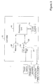
- the controller 16 of the vehicle 10 may include one or more components. As shown in Figure 3 , the controller 16 may include a processing unit 18, a cruise control module 19, memory 20 in communication with the processing unit 18, an input/output block 22 in communication with the processing unit 18, and/or one or more other components.
- the memory 20 may include one or more control system algorithms and/or other algorithms and the processing unit 18 may execute instructions (e.g., software code or other instructions) related to the algorithms in the memory 20.
- the memory 20 may be local and/or remote memory.
- the memory 20 may be one or more portions of memory and/or may be any type of memory and/or may include any combination of types of memory.
- the memory may be volatile memory, nonvolatile memory, random access memory (RAM), FLASH, read-only memory (ROM), and/or one or more other types of memory.
- the input/output block 22 may include one or more ports for communicating with components of the vehicle 10 and/or remote components (e.g., remote computing devices, global positioning systems, and so forth)
- the input/output block 22 may include an input port 24 for receiving a target speed, one or more measures of parameters, and/or other information, where the received target speed, one or more measures of parameters, and/or other information may be sent to the processing unit 18.
- the one or more measures of parameters may be related to a travel horizon of the vehicle or other features and may include one or more measures of a mass of the vehicle, a road grade of a road on which the vehicle is or is to be positioned over the travel horizon and/or one or more other measures of parameters.
- the input/output block 22 may include an output port 26, where the output port 26 may be used by the controller 16 to provide one or more operating set points to the propulsion device and/or provide one or more other pieces of information.
- the operating set points of the propulsion device may be related to set points for actuators of a combustion engine or an electric motor.
- Actuators of a combustion engine may include one or more of a turbocharger waste gate (WG), variable geometry turbocharger (VGT), exhaust gas recirculation (EGR), start of injection (SOI), throttling valve (TV), and so on.
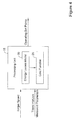
- the processing unit 18 is depicted with illustrative inputs and outputs, where the outputs may be based at least in part on the inputs.
- the output of the processing unit may include operating set points for the propulsion device 14 based, at least in part, on received one or more measures of the parameters related to a travel horizon.
- the processing unit 18 may include a vehicle operating model and a cost function 28.
- the vehicle operating model may be or may include a model of energy balances of the vehicle 10, such as an energy losses model 30 for the vehicle 10.
- the processing unit 18 of the controller 16 may optimize a cost function over a travel horizon, where the cost function is based at least in part on estimated energy losses according to the energy losses model 30 to set an actual speed for the vehicle.
- the energy losses model 30 may estimate the energy losses over a travel horizon for a vehicle 10. In some cases, the energy losses model 30 may take into account losses of power and/or recoverable power.
- Example losses of power may include power loss due to aerodynamic drag for the vehicle 10, power loss due to friction of tires and powertrain (e.g., which may include engine friction), power loss due to conversion of primary energy into mechanical energy in the propulsion device 14 (e.g. thermal losses of a combustion engine), and/or other power losses.
- Recoverable power may include power related to the grade-force and acceleration power.
- the losses model 30 may take into account recoverable power of the vehicle 10, including but not limited to power related to the grade-force acting on vehicle 10 and acceleration power.
- Power related to the grade-force acting on a vehicle may be accumulated as potential energy of the vehicle 10.
- the grade angle may be road grades of roads on which the vehicle 10 is to travel over the travel horizon and/or a current road grade of a road on which the vehicle 10 may be positioned. Further, the grade angle may be determined by sensors in the vehicle 10, a GPS in communication with the controller 16 of the vehicle 10, a maps program saved in the memory 20 of the controller 16, a remote maps program in communication with the controller 16, and/or in one or more other manners.
- f(u e ) is an algebraic function for the vehicle propulsion force depending on variable u e
- u e is a variable that could be one or more parameters of the propulsion device including brake torque
- T brake m is the mass of the vehicle 10 and its contents
- ⁇ 1 is a constant proportional to a combination of a drag coefficient and a quadratic term of friction
- ⁇ 2 is a constant proportional to a linear term of friction
- ⁇ 3 is a constant proportional to a friction force
- g is a gravitational acceleration constant
- ⁇ is a grade angle of the route on which the vehicle is traveling
- v is the velocity of the vehicle 10.
- ⁇ e ( ⁇ e , u e ) is a conversion efficiency of the propulsion device 14 (e.g.
- the thermal efficiency of a combustion engine) of the vehicle 10 may typically be a value between zero and one
- n e is propulsion device speed
- u e is a variable that could be one or more parameters of the propulsion device including brake torque, T brake , and P 1,1 , P 1,1 , P g , P a are power terms according to equations (1) to (4) above.
- a physically maximum possible efficiency e.g. the Carnot efficiency of a combustion engine
- an effective conversion efficiency may be considered.
- distance-specific total primary-energy e.g. fuel energy or electrical energy
- E tot 1 v mean ⁇ T ⁇ 0 T 1 ⁇ e n e u e ⁇ P l , 1 + P l , 2 + P g + P a dt
- v mean is an average velocity of the vehicle over the travel horizon
- T is a travel horizon of the vehicle
- ⁇ e ( n e , u e ) is a conversion efficiency of the propulsion device 14 (e.g. a thermal efficiency of a combustion engine) of the vehicle 10
- n e is propulsion device speed
- u e is a variable that could be one or more parameters of the propulsion device including brake torque, T brake .
- the distance-specific total primary-energy (e.g. fuel energy) model of equation (8) has typically been used to model the energy consumed by a vehicle 10 over a travel horizon.
- v mean is an average velocity of the vehicle over the travel horizon
- T is a travel horizon of the vehicle 10
- the first summand in the integral represents power losses due to conversion efficiency of the propulsion device (see equation (7))
- P 1,1 and P 1,2 represent drag and friction losses of the vehicle according to equations (1) and (2), respectively.
- the cost function 28 shown in equation (10) may be extended or expanded to include other terms based on user preferences.
- user preferences may include a desired maximum change in acceleration, a desired maximum acceleration, a desired time to travel a travel horizon, and/or one or more other desired factors.
- the controller 16 of the vehicle 10 may be able to more precisely calculate an optimized speed for the vehicle to travel based on a target speed for the vehicle 10.
- the optimization technique for a vehicle utilizing an energy losses model 30 of the vehicle 10 may be used in one or more approaches or methods, including a cruise control system approach.
- Figure 5 depicts one example of using the above described energy losses model 30 in a process 100 for establishing an actual speed of a vehicle 10 from a user-specified target speed.
- the process 100 may include at step 102 receiving a target speed for a vehicle.
- the target speed for the vehicle 10 may be received at the controller 16 in communication with the propulsion device 14 that may power the vehicle 10.
- the process 100 may include optimizing a cost function 30 over a travel horizon of the vehicle 10.
- the cost function 28 may be optimized over the travel horizon of the vehicle 10 based, at least in part, on energy losses of the vehicle over the travel horizon relative to the received target speed.
- the controller 16 may use the cost function 28 utilizing a model as in equation (9) to determine and minimize the energy losses of the vehicle 10 over the travel horizon to determine an optimal speed of the vehicle 10 in view of the target speed.
- an actual speed of the vehicle 10 may be set based, at least in part, on optimizing the cost function over the travel horizon.
- the controller 16 of the vehicle 10 may optimize the cost function over the travel horizon. However, in some cases, one or more other controllers may optimize the cost function over the travel horizon and input the results of optimization to the controller 16 for determining propulsion-device set points (e.g. engine brake torque).
- propulsion-device set points e.g. engine brake torque
- the actual speed set may be the optimal speed of the vehicle identified by the cost function 28.
- the optimal speed may be presented to a user (e.g., driver) of the vehicle and the user may be given an option of setting the speed of the vehicle at the determined optimal speed or some other speed based on knowing the optimal speed for the user's requirements and the energy losses of the vehicle.
- the approach 100 may be used in a cruise control module 19 of the controller 16.
- the cruise control module 19 may control the propulsion device to establish a speed of the vehicle 10.
- the target speed may be a user specified cruise control speed and the set actual speed may be the established speed of the vehicle.
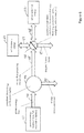
- Figure 6 is a diagram of energy flows that correspond to the powers in equations.
- the power distribution "part” may balance the energy flows (powers) depending on physics and parameters such as vehicle mass, road grade, vehicle speed, such that the sum of all energy flows connected to the power distribution "part” is zero.
- Symbol 41 may resemble a primary energy reservoir (e.g., fuel reservoir or battery) having a primary-energy flow 42 to a propulsion device 43 (e.g., combustion engine). Energy conversion losses 44 may flow from device 43.
- An energy flow 45 propelling a vehicle may go to a symbol 46 indicating parameter dependent distribution (balancing) of energy flows (e.g., parameters of speed, road grade, vehicle mass, so forth. From symbol 46 is shown a flow 49 of drag and friction losses.
- a vehicle system may include a vehicle, a propulsion device such as a combustion engine, and a controller.
- the propulsion device may be configured to at least partially power the vehicle and the controller may be in communication with the propulsion device for controlling the propulsion device according to a target speed of the vehicle.
- the controller may include a model of energy balances of the vehicle and may be configured to use the model to estimate energy losses over a travel horizon of the vehicle.
- the controller may be configured to optimize in each processing step a cost function over the travel horizon of the vehicle based at least in part on the estimated energy losses to set an actual speed for the vehicle.
- controller of the vehicle system may be configured to optimize the cost function at least in part by minimizing the energy losses relative to the target speed.
- controller of the vehicle system may include a cruise control module and the target speed is a user specified cruise control speed.
- the actual speed of the vehicle system as set by the controller may be the actual speed of the vehicle after a user has specified the user specified cruise control speed.
- the travel horizon of the vehicle of the vehicle system may be a time interval.
- the model of energy balances of the vehicle may include a parameter of road grades of roads on which the vehicle may travel over the travel horizon.
- the model of energy balances of the vehicle system may include a parameter of a current road grade on which the vehicle is positioned.
- the model of energy balances of the vehicle of the vehicle system may include a mass of the vehicle as a parameter.
- the estimated energy losses of the vehicle system over the travel horizon may include energy loss due to aerodynamic drag of the vehicle.
- the estimated energy losses of the vehicle system over the travel horizon may include energy loss due to friction.
- the estimated energy losses of the vehicle over the travel horizon may include energy loss due to energy-conversion loss propulsion device (e.g., thermal loss from the engine) of the vehicle.
- energy-conversion loss propulsion device e.g., thermal loss from the engine
- An approach for establishing an actual speed of a vehicle from a user-specified target speed may include receiving a target speed for a vehicle.
- the target speed is received at a controller in communication with a propulsion device configured to at least partially power the vehicle, optimizing a cost function over a travel horizon based at least in part on energy losses of the vehicle over the travel horizon relative to the target speed, and setting an actual speed of the vehicle based at least in part on optimizing the cost function over the travel horizon.
- controller in the approach may include a model of vehicle energy balances to calculate the energy losses of the vehicle over the travel horizon.
- the approach may include optimizing a cost function over a travel horizon based at least in part on energy losses of the vehicle over a travel horizon based, at least in part, on minimizing energy losses of the vehicle over the travel horizon relative to target speed to establish an optimal speed.
- the approach may further include obtaining one or more measures of parameters related to the travel horizon, wherein optimizing the cost function may take into account the obtained one or more measures of parameters related to the travel horizon.
- controller in the approach may include a cruise control module configured to control the propulsion device to establish a speed of the vehicle and the target speed may be a user specified cruise control speed and the set actual speed may be the established speed of the vehicle.
- a controller may be provided for a vehicle powered by a propulsion device.
- the controller may include a processing unit, an input for receiving one or more measures of parameters at the processing unit, and an output for providing one or more operating set points to the propulsion device based at least in part on the received one or more measures of parameters.
- the processing unit may receive a target speed for the vehicle over a travel horizon, may obtain one or more measures of parameters related to a travel horizon, and may optimize a cost function of the vehicle to provide operating set points for the propulsion device by minimizing energy losses of the vehicle relative to the received target speed and one or more obtained measures of parameters related to the travel horizon.
- the provided operating conditions determined by the controller may establish an actual speed of the vehicle.
- the energy losses minimized may include one or more of energy loss due to aerodynamic drag, friction present in the propulsion device, the powertrain, and in the tires, and a conversion loss from the propulsion device (e.g., thermal loss from the combustion engine).
- the obtained measures of parameters related to a travel horizon may include one or more of a mass of the vehicle and a road grade of a road on which the vehicle is positioned over a travel horizon.
Landscapes
- Engineering & Computer Science (AREA)
- Transportation (AREA)
- Mechanical Engineering (AREA)
- Automation & Control Theory (AREA)
- Chemical & Material Sciences (AREA)
- Combustion & Propulsion (AREA)
- Physics & Mathematics (AREA)
- Human Computer Interaction (AREA)
- Radar, Positioning & Navigation (AREA)
- Aviation & Aerospace Engineering (AREA)
- Mathematical Physics (AREA)
- Remote Sensing (AREA)
- General Physics & Mathematics (AREA)
- Control Of Driving Devices And Active Controlling Of Vehicle (AREA)
- Artificial Intelligence (AREA)
- Health & Medical Sciences (AREA)
- Evolutionary Computation (AREA)
- Game Theory and Decision Science (AREA)
- Medical Informatics (AREA)
- Business, Economics & Management (AREA)
- Hybrid Electric Vehicles (AREA)
- Electric Propulsion And Braking For Vehicles (AREA)
- Control Of Vehicle Engines Or Engines For Specific Uses (AREA)
Abstract
Description
- This present application claims the benefit of
U.S. Provisional Patent Application No. 62/201,388, filed August 05, 2015 U.S. Provisional Patent Application No. 62/201,388, filed August 05, 2015 - The present disclosure pertains to vehicle systems, and particularly to controlling speeds of a vehicle. More particularly, the disclosure pertains to performance improvement in speed control systems.
- The disclosure reveals systems and approaches for controlling speeds of a vehicle. A vehicle system may include a vehicle, a propulsion device, such as a combustion engine or an electric motor, and a controller in communication with the propulsion device. The propulsion device may at least partially power the vehicle and may consume primary energy, such as fuel or electric energy stored in a battery. The controller may control the propulsion device. In some cases, the controller may control the propulsion device according to a target speed of the vehicle.
- The controller may include a model of energy balances of the vehicle and may use the model to estimate energy losses over a travel horizon of the vehicle. The model estimating energy losses over a travel horizon of the vehicle may take into account one or more measures of parameters related to the travel horizon, where the parameters related to the travel horizon may include one or more of a mass of the vehicle and a road grade of a road on which the vehicle is positioned over the travel horizon, and one or more other parameters may be utilized. In some cases, the controller may use the estimated energy losses over the travel horizon of the vehicle to optimize a cost function over the travel horizon and set an actual speed for the vehicle.
-
-
Figure 1 is a schematic diagram depicting an illustrative travel of a vehicle from place A to place B; -
Figure 2 is a schematic block diagram of an illustrative vehicle; -
Figure 3 is a schematic block diagram of a controller of the illustrative vehicle inFigure 2 ; -
Figure 4 is a schematic block diagram of illustrative inputs to and outputs from a processing unit of the illustrative controller ofFigure 3 ; -
Figure 5 is a schematic flow diagram of an illustrative approach for controlling a speed of a vehicle; and -
Figure 6 is a diagram of energy flows that correspond to powers in equations. - The present system and approach, as described herein and/or shown in the Figures, may incorporate one or more processors, computers, controllers, user interfaces, wireless and/or wire connections, and/or the like, wherever desired.
- Typical operation of a vehicle may have the goal to transport people or goods from place A to place B, along a predetermined route. An operator of the vehicle and/or potential passengers of the vehicle, hereafter referred to as users, may have certain expectations and requirements connected to transportation from place A to place B. Illustratively, users may have expectations and/or requirements that have to do with comfort of driving and/or riding, the duration of the transport from place A to place B, fuel required to reach place B from place A, and/or one or more other expectations or requirements. True user expectations and/or requirements, in many cases, may trade-off different individual expectations and/or requirements of a user over a horizon, which may exceed many travel horizons that are practical in context of solving an optimization problem over the travel horizon, and which may possibly even exceed a route of a trip from place A to place B. The expectations and requirements of users may be turned into an optimization issue to maximize overall satisfaction of users of a vehicle.
- In some cases, a comfort of driving and/or riding expectation and/or requirement may be expressed in terms of acceleration and/or change of acceleration of the vehicle. For a fuel consumption expectation and/or requirement, one or more different terms may be used. In many cases, a scaled, distance-specific fuel consumption model may be used, but this is not always the case. Illustratively, a scaled, distance-specific fuel consumption related optimization variable used in a cost function may be minimized by an optimizer and/or controller of a vehicle.
- In one example, a scaled, distance-specific fuel consumption optimization model may not be desirable for use in an optimization problem that does not solve the optimization problem for the complete remaining route from place A to place B, but rather only for a limited future horizon representing a part of the remaining route to place B. Such limited horizon optimizers that, amongst others minimize the fuel consumption and that do not solve the optimization problem for the entire remaining trip from place A to place B may be expected to become a common solution for real-world implementable vehicle-speed control solutions in next generation vehicle systems.
- An issue with optimizing a distance-specific fuel consumption parameter for a travel horizon may be that such an approach does not consider energy consumed, but rather fuel consumed. In particular, optimizing a distance-specific fuel consumption parameter may be related to the fuel mass consumed over a travel horizon by a change in altitude or change in vehicle speed over that travel horizon. A fuel mass flow signal (measured or estimated from propulsion-device operation) may correspond to a flow of chemical energy (e.g., power) invested for propulsion of the vehicle. However, a portion of this chemical energy flow invested may not necessarily be optimizeable because it is outside of the scope of the optimization problem. Additionally, a part of the chemical energy flow invested may be recollected completely or at least partially at the end of the interval and thus may not be necessarily consumed in an energetic sense.
- In the general case, fuel consumed may not necessarily be proportional to energy consumed in a context of a user's expectations and/or requirements. This may be so because a part of fuel energy consumed by a propulsion device (e.g., a combustion engine, an electric motor, or other propulsion device) of a vehicle might still be available in a form of an increased potential or kinetic energy in the vehicle at the end of the horizon with respect to the initial level of potential or kinetic energy. In one example, an investment of fuel energy into a vehicle energy (e.g., potential or kinetic energy of the vehicle) over the travel horizon (e.g., when driving uphill or when accelerating), the fuel consumption over the horizon may be higher than for a case where the vehicle energy is equal at a beginning and at an end of the travel horizon. This difference in fuel consumption may lead to a bias of the user-defined trade-off between a user's true expectations and/or requirements if the vehicle energy is ignored in the optimization problem. In another example, if a change in vehicle energy is not considered explicitly in an optimization problem, a fuel-cost over a travel horizon may appear to be higher resulting in over-weighting of the fuel consumption related expectations and/or requirements. Similarly, if a vehicle energy decreases over a travel horizon, the fuel consumption related expectations and/or requirements may be under-weighted.
- Further, potential energy of a vehicle with a given mass may change as the vehicle travels. As long as the horizon of at least a portion along a route from place A to place B and/or the vehicle mass are not changed, a potential energy of the vehicle connected to differences in altitude over the horizon may have to be invested and it does not necessarily matter if potential energy is invested with high or lower power (e.g., high or low speed). Further, as speed (e.g., kinetic energy) may change over a travel horizon, the fuel mass flow may be higher during phases of acceleration than in phases of constant speed (e.g., zero acceleration) because additional chemical energy flow may need to be invested to accelerate the vehicle. Therefore, fuel consumption of the vehicle may seem high during acceleration, but the additional kinetic energy at the end of the travel horizon may be available in the vehicle and may be recovered completely for moving the vehicle forward on the route. As a result, there may be a need to correct a fuel energy flow invested over the travel horizon to take into account a change in vehicle potential and kinetic energy when an altitude of a vehicle at an end of a route (e.g., the end of the travel horizon) may be different than an altitude of the vehicle at a beginning of the route (e.g., the beginning of the travel horizon) and/or when a speed the vehicle at an end of a route (e.g., the end of the travel horizon) may be different from a speed of the vehicle at a beginning of a route (e.g., the beginning of the travel horizon).
- To address the bias issue that may result when distance-specific fuel consumption parameters are optimized without considering vehicle energy, a more appropriate optimization approach may be used such that true user expectations and/or requirements may be met when optimizing a vehicle speed trajectory from place A to place B. A more appropriate optimization approach that addresses the bias issue may include an optimization approach that uses a cost function taking into consideration energy losses of a vehicle over a travel horizon by subtracting the fuel-energy parameters required for a change in kinetic energy of the vehicle and for the change in potential energy of the vehicle from the fuel energy invested over a travel horizon. That is, instead of considering fuel energy or fuel power (e.g., fuel mass flow) in a cost function of an optimization problem, the cost function of the optimization problem may consider energy losses (e.g., a part of the fuel mass flow that is being consumed by losses, such as friction, drag, and so forth). In one example, a fuel mass flow signal that may typically be used as an input for an optimization problem may be corrected by subtracting the rate of potential energy change of the vehicle and by subtracting the rate of kinetic energy change of the vehicle, both corrected by a lower heating value of fuel in the vehicle.
- To make use of an optimization approach for controlling a vehicle (e.g., a vehicle speed or other vehicle variable), a vehicle controller may utilize a mathematical model of energy flows and/or balances of the vehicle. Further, expectations and/or requirements of users and the relative importance of each of the expectations and/or requirements may be considered in the optimization approach. Some of the expectations and/or requirements of users may include, but are not limited to, limits on fuel consumption, limits on deviation from a desired speed (e.g., a target speed), limits on speed, limits on deviation from desired distance from or to a lead vehicle (e.g., a vehicle in front of a subject vehicle for which optimization is desired), limits on a distance to a lead vehicle, limits on vehicle acceleration, and/or other expectations and/or requirements of users.
- In some cases, the optimization approach for controlling a vehicle may consider estimated and/or measured values of the vehicle mass and/or a current or future road grade of a road on which the vehicle travels from place A to place B. Such mass of the vehicle and road grade of a road on which the vehicle travels may be measured by sensors on the vehicle. Alternatively, or in addition, a road grade may be provided to a controller of the vehicle via computer program (e.g., a maps/directions program) and/or via a positioning system (e.g., a global position system (GPS) or other positioning system) in communication with the controller of the vehicle.
- The disclosed optimization approach using a model of vehicle energy flows and balances may be further described below. Illustratively, the model of vehicle energy flows and balances may be used to estimate the power losses of the vehicle over a travel horizon. The calculated power losses may then be used in a cost function of the optimization problem to minimize a trade-off of user expectations and/or requirements (e.g., a total cost) over the travel horizon.
- Turning to the figures,
Figure 1 depicts a schematic elevation view of anillustrative vehicle 10 on aroute 12. Thevehicle 10 may be traveling from place A to place B along theroute 12 or at least part of the route from place A to place B. Any interval between the current vehicle position to place B may represent a travel horizon where the travel horizon may be measured in time (e.g., a time interval) or distance (e.g., a distance interval), or both time and distance. -
Figure 2 depicts illustrative components of avehicle 10. For example, as shown inFigure 2 , thevehicle 10 may include a propulsion device 14, such as a combustion engine (as shown), electric motor, or other propulsion device, and acontroller 16. Additionally, or alternatively, thevehicle 10 may include one or other components. The propulsion device 14 may be configured to at least partially power thevehicle 10. In some cases, thecontroller 16 may be in communication with the propulsion device and may control the propulsion device according to one or more parameters. In one example, thecontroller 16 may be configured to control the propulsion device based, at least in part, according to a target speed of thevehicle 10. - A target speed of the
vehicle 10 may be selected in any manner. For example, a target speed of thevehicle 10 may be pre-set by a manufacturer or user, the target speed may be automatically set based on local speed limits, the target speed may be set by a user during operation of the vehicle, and/or the target speed may set in one or more other manners. - The
controller 16 of thevehicle 10 may include one or more components. As shown inFigure 3 , thecontroller 16 may include aprocessing unit 18, acruise control module 19,memory 20 in communication with theprocessing unit 18, an input/output block 22 in communication with theprocessing unit 18, and/or one or more other components. In one example, thememory 20 may include one or more control system algorithms and/or other algorithms and theprocessing unit 18 may execute instructions (e.g., software code or other instructions) related to the algorithms in thememory 20. - The
memory 20 may be local and/or remote memory. Thememory 20 may be one or more portions of memory and/or may be any type of memory and/or may include any combination of types of memory. For example, the memory may be volatile memory, nonvolatile memory, random access memory (RAM), FLASH, read-only memory (ROM), and/or one or more other types of memory. - The input/
output block 22 may include one or more ports for communicating with components of thevehicle 10 and/or remote components (e.g., remote computing devices, global positioning systems, and so forth) In one example, the input/output block 22 may include aninput port 24 for receiving a target speed, one or more measures of parameters, and/or other information, where the received target speed, one or more measures of parameters, and/or other information may be sent to theprocessing unit 18. In one example, the one or more measures of parameters may be related to a travel horizon of the vehicle or other features and may include one or more measures of a mass of the vehicle, a road grade of a road on which the vehicle is or is to be positioned over the travel horizon and/or one or more other measures of parameters. Further, the input/output block 22 may include anoutput port 26, where theoutput port 26 may be used by thecontroller 16 to provide one or more operating set points to the propulsion device and/or provide one or more other pieces of information. In one example, the operating set points of the propulsion device may be related to set points for actuators of a combustion engine or an electric motor. Actuators of a combustion engine may include one or more of a turbocharger waste gate (WG), variable geometry turbocharger (VGT), exhaust gas recirculation (EGR), start of injection (SOI), throttling valve (TV), and so on. - Turning to
Figure 4 , theprocessing unit 18 is depicted with illustrative inputs and outputs, where the outputs may be based at least in part on the inputs. In some cases, the output of the processing unit may include operating set points for the propulsion device 14 based, at least in part, on received one or more measures of the parameters related to a travel horizon. - The
processing unit 18 may include a vehicle operating model and acost function 28. In one example, the vehicle operating model may be or may include a model of energy balances of thevehicle 10, such as anenergy losses model 30 for thevehicle 10. Theprocessing unit 18 of thecontroller 16 may optimize a cost function over a travel horizon, where the cost function is based at least in part on estimated energy losses according to theenergy losses model 30 to set an actual speed for the vehicle. - The
energy losses model 30 may estimate the energy losses over a travel horizon for avehicle 10. In some cases, theenergy losses model 30 may take into account losses of power and/or recoverable power. Example losses of power may include power loss due to aerodynamic drag for thevehicle 10, power loss due to friction of tires and powertrain (e.g., which may include engine friction), power loss due to conversion of primary energy into mechanical energy in the propulsion device 14 (e.g. thermal losses of a combustion engine), and/or other power losses. Recoverable power may include power related to the grade-force and acceleration power. - Power losses due to aerodynamic drag and a quadratic term of friction may be represented by:

vehicle 10. - Power losses due to friction of tires on the
vehicle 10 and a powertrain of thevehicle 10 may be represented by:
vehicle 10. - As mentioned above, the
losses model 30 may take into account recoverable power of thevehicle 10, including but not limited to power related to the grade-force acting onvehicle 10 and acceleration power. Power related to the grade-force acting on a vehicle may be represented by:
vehicle 10. Power related to the grade-force acting on a vehicle may be accumulated as potential energy of thevehicle 10. The grade angle may be road grades of roads on which thevehicle 10 is to travel over the travel horizon and/or a current road grade of a road on which thevehicle 10 may be positioned. Further, the grade angle may be determined by sensors in thevehicle 10, a GPS in communication with thecontroller 16 of thevehicle 10, a maps program saved in thememory 20 of thecontroller 16, a remote maps program in communication with thecontroller 16, and/or in one or more other manners. - Acceleration power may be represented by:

vehicle 10 and its contents, a is the acceleration of thevehicle 10, and v is the velocity of thevehicle 10. Acceleration power may be accumulated as kinetic energy of thevehicle 10. - Acceleration of the vehicle may be represented by:

vehicle 10 and its contents, θ 1 is a constant proportional to a combination of a drag coefficient and a quadratic term of friction, θ 2 is a constant proportional to a linear term of friction, θ 3 is a constant proportional to a friction force, g is a gravitational acceleration constant, ϕ is a grade angle of the route on which the vehicle is traveling, and v is the velocity of thevehicle 10. - Velocity of the vehicle may be represented by:

vehicle 10, a is the acceleration of thevehicle 10. - Power losses due to conversion efficiency of the propulsion device may be represented by:

vehicle 10 and may typically be a value between zero and one, ne is propulsion device speed, ue is a variable that could be one or more parameters of the propulsion device including brake torque, Tbrake , and P1,1 , P1,1 , Pg , Pa are power terms according to equations (1) to (4) above. In some cases, to determine power losses due to conversion efficiency of the propulsion device, only the difference between a physically maximum possible efficiency (e.g. the Carnot efficiency of a combustion engine) and an effective conversion efficiency may be considered. - Generally, distance-specific total primary-energy (e.g. fuel energy or electrical energy) over a travel horizon may be modeled by:

vehicle 10, ηe (ne ,ue ) is a conversion efficiency of the propulsion device 14 (e.g. a thermal efficiency of a combustion engine) of thevehicle 10, ne is propulsion device speed, ue is a variable that could be one or more parameters of the propulsion device including brake torque, Tbrake . - The distance-specific total primary-energy (e.g. fuel energy) model of equation (8) has typically been used to model the energy consumed by a
vehicle 10 over a travel horizon. However, herein a different proposed model may utilize distance specific total losses of energy of thevehicle 10 based on the energy losses referred to above and may be represented by:
vehicle 10, the first summand in the integral represents power losses due to conversion efficiency of the propulsion device (see equation (7)), and P1,1 and P1,2 represent drag and friction losses of the vehicle according to equations (1) and (2), respectively. - The energy losses model may then be used in a
cost function 28 to determine an optimum speed of thevehicle 10 over a travel horizon, which may be represented as follows as a sum over Nhorz incremental parts of the travel horizon:
energy losses model 30 using equation (9) or theenergy losses model 30 using the distance-specific primary-energy model according to equation (8)), En is an energy normalization factor that may be a function of target speed of thevehicle 10, vi is an average speed of thevehicle 10 over increment i of the travel horizon, vref is a target speed of the vehicle, and vn is a speed normalization factor of the vehicle. Thecost function 28 shown in equation (10) may be extended or expanded to include other terms based on user preferences. Such user preferences may include a desired maximum change in acceleration, a desired maximum acceleration, a desired time to travel a travel horizon, and/or one or more other desired factors. - Thus, based on using an energy losses model for a
vehicle 10 traveling over a travel horizon one can obtain a more precise understanding of energy consumed by thevehicle 10 over the travel horizon. From this, thecontroller 16 of thevehicle 10 may be able to more precisely calculate an optimized speed for the vehicle to travel based on a target speed for thevehicle 10. - The optimization technique for a vehicle utilizing an
energy losses model 30 of thevehicle 10 may be used in one or more approaches or methods, including a cruise control system approach.Figure 5 depicts one example of using the above describedenergy losses model 30 in aprocess 100 for establishing an actual speed of avehicle 10 from a user-specified target speed. Theprocess 100 may include atstep 102 receiving a target speed for a vehicle. In some cases, the target speed for thevehicle 10 may be received at thecontroller 16 in communication with the propulsion device 14 that may power thevehicle 10. Atstep 104, theprocess 100 may include optimizing acost function 30 over a travel horizon of thevehicle 10. In some cases, thecost function 28 may be optimized over the travel horizon of thevehicle 10 based, at least in part, on energy losses of the vehicle over the travel horizon relative to the received target speed. For example, thecontroller 16 may use thecost function 28 utilizing a model as in equation (9) to determine and minimize the energy losses of thevehicle 10 over the travel horizon to determine an optimal speed of thevehicle 10 in view of the target speed. Atstep 106, an actual speed of thevehicle 10 may be set based, at least in part, on optimizing the cost function over the travel horizon. - The
controller 16 of thevehicle 10 may optimize the cost function over the travel horizon. However, in some cases, one or more other controllers may optimize the cost function over the travel horizon and input the results of optimization to thecontroller 16 for determining propulsion-device set points (e.g. engine brake torque). - In some cases, the actual speed set may be the optimal speed of the vehicle identified by the
cost function 28. Alternatively or in addition, the optimal speed may be presented to a user (e.g., driver) of the vehicle and the user may be given an option of setting the speed of the vehicle at the determined optimal speed or some other speed based on knowing the optimal speed for the user's requirements and the energy losses of the vehicle. - In some cases, the
approach 100 may be used in acruise control module 19 of thecontroller 16. Thecruise control module 19 may control the propulsion device to establish a speed of thevehicle 10. In thecruise control module 19, the target speed may be a user specified cruise control speed and the set actual speed may be the established speed of the vehicle. -
Figure 6 is a diagram of energy flows that correspond to the powers in equations. The power distribution "part" may balance the energy flows (powers) depending on physics and parameters such as vehicle mass, road grade, vehicle speed, such that the sum of all energy flows connected to the power distribution "part" is zero.Symbol 41 may resemble a primary energy reservoir (e.g., fuel reservoir or battery) having a primary-energy flow 42 to a propulsion device 43 (e.g., combustion engine).Energy conversion losses 44 may flow fromdevice 43. Anenergy flow 45 propelling a vehicle may go to asymbol 46 indicating parameter dependent distribution (balancing) of energy flows (e.g., parameters of speed, road grade, vehicle mass, so forth. Fromsymbol 46 is shown aflow 49 of drag and friction losses. There may be a twoway flow 47 betweensymbol 46 and a vehicle kinetic energy block 51. Also, there may be a twoway flow 48 betweensymbol 46 and a vehiclepotential energy block 52. - The following is a recap of the above disclosure. A vehicle system may include a vehicle, a propulsion device such as a combustion engine, and a controller. The propulsion device may be configured to at least partially power the vehicle and the controller may be in communication with the propulsion device for controlling the propulsion device according to a target speed of the vehicle. The controller may include a model of energy balances of the vehicle and may be configured to use the model to estimate energy losses over a travel horizon of the vehicle. The controller may be configured to optimize in each processing step a cost function over the travel horizon of the vehicle based at least in part on the estimated energy losses to set an actual speed for the vehicle.
- Further, the controller of the vehicle system may be configured to optimize the cost function at least in part by minimizing the energy losses relative to the target speed.
- Further, the controller of the vehicle system may include a cruise control module and the target speed is a user specified cruise control speed.
- The actual speed of the vehicle system as set by the controller may be the actual speed of the vehicle after a user has specified the user specified cruise control speed.
- The travel horizon of the vehicle of the vehicle system may be a time interval.
- The model of energy balances of the vehicle may include a parameter of road grades of roads on which the vehicle may travel over the travel horizon.
- The model of energy balances of the vehicle system may include a parameter of a current road grade on which the vehicle is positioned.
- The model of energy balances of the vehicle of the vehicle system may include a mass of the vehicle as a parameter.
- The estimated energy losses of the vehicle system over the travel horizon may include energy loss due to aerodynamic drag of the vehicle.
- The estimated energy losses of the vehicle system over the travel horizon may include energy loss due to friction.
- The estimated energy losses of the vehicle over the travel horizon may include energy loss due to energy-conversion loss propulsion device (e.g., thermal loss from the engine) of the vehicle.
- An approach for establishing an actual speed of a vehicle from a user-specified target speed may include receiving a target speed for a vehicle. The target speed is received at a controller in communication with a propulsion device configured to at least partially power the vehicle, optimizing a cost function over a travel horizon based at least in part on energy losses of the vehicle over the travel horizon relative to the target speed, and setting an actual speed of the vehicle based at least in part on optimizing the cost function over the travel horizon.
- Further, the controller in the approach may include a model of vehicle energy balances to calculate the energy losses of the vehicle over the travel horizon.
- Further, the approach may include optimizing a cost function over a travel horizon based at least in part on energy losses of the vehicle over a travel horizon based, at least in part, on minimizing energy losses of the vehicle over the travel horizon relative to target speed to establish an optimal speed.
- The approach may further include obtaining one or more measures of parameters related to the travel horizon, wherein optimizing the cost function may take into account the obtained one or more measures of parameters related to the travel horizon.
- Further, the controller in the approach may include a cruise control module configured to control the propulsion device to establish a speed of the vehicle and the target speed may be a user specified cruise control speed and the set actual speed may be the established speed of the vehicle.
- A controller may be provided for a vehicle powered by a propulsion device. The controller may include a processing unit, an input for receiving one or more measures of parameters at the processing unit, and an output for providing one or more operating set points to the propulsion device based at least in part on the received one or more measures of parameters. The processing unit may receive a target speed for the vehicle over a travel horizon, may obtain one or more measures of parameters related to a travel horizon, and may optimize a cost function of the vehicle to provide operating set points for the propulsion device by minimizing energy losses of the vehicle relative to the received target speed and one or more obtained measures of parameters related to the travel horizon.
- The provided operating conditions determined by the controller may establish an actual speed of the vehicle.
- The energy losses minimized may include one or more of energy loss due to aerodynamic drag, friction present in the propulsion device, the powertrain, and in the tires, and a conversion loss from the propulsion device (e.g., thermal loss from the combustion engine).
- The obtained measures of parameters related to a travel horizon may include one or more of a mass of the vehicle and a road grade of a road on which the vehicle is positioned over a travel horizon.
- In the present specification, some of the matter may be of a hypothetical or prophetic nature although stated in another manner or tense.
- Although the present system and/or approach has been described with respect to at least one illustrative example, many variations and modifications will become apparent to those skilled in the art upon reading the specification. It is therefore the intention that the appended claims be interpreted as broadly as possible in view of the related art to include all such variations and modifications.
Claims (20)
- A vehicle system comprising:a vehicle;a propulsion device configured to at least partially power the vehicle; anda controller in communication with the propulsion device for controlling the propulsion device according to a target speed of the vehicle; and
wherein:the controller includes a model of energy balances of the vehicle and is configured to use the model to estimate energy losses over a travel horizon of the vehicle; andthe controller is configured to optimize a cost function over the travel horizon of the vehicle based at least in part on the estimated energy losses to set an actual speed for the vehicle. - The vehicle system of claim 1, wherein the controller is configured to optimize the cost function at least in part by minimizing the energy losses relative to the target speed.
- The vehicle system of claim 1, wherein the controller includes a cruise control module and the target speed is a user specified cruise control speed.
- The vehicle system of claim 3, wherein the set actual speed for the vehicle is the actual speed of the vehicle after a user has specified the user specified cruise control speed.
- The vehicle system of claim 1, wherein the travel horizon of the vehicle is a time interval.
- The vehicle system of claim 5, wherein the model of energy balances of the vehicle includes a parameter of road grades of roads on which the vehicle is to travel over the travel horizon.
- The vehicle system of claim 1, wherein the model of energy balances of the vehicle includes a parameter of a current road grade on which the vehicle is positioned.
- The vehicle system of claim 1, wherein the model of energy balances of the vehicle includes a mass of the vehicle as a parameter.
- The vehicle system of claim 1, wherein the estimated energy losses includes energy loss due to aerodynamic drag.
- The vehicle system of claim 1, wherein the estimated energy losses include energy loss due to friction.
- The vehicle system of claim 1, wherein the estimated energy losses include energy loss due to conversion efficiency from the propulsion device.
- A process for establishing an actual speed of a vehicle from a user-specified target speed, the process comprising:receiving a target speed for a vehicle, where the target speed is received at a controller in communication with a propulsion device configured to at least partially power the vehicle;optimizing a cost function over a travel horizon based at least in part on energy losses of the vehicle over the travel horizon relative to the target speed; andsetting an actual speed of the vehicle based at least in part on optimizing the cost function over the travel horizon.
- The process of claim 12, wherein the controller includes a model of vehicle energy balances to calculate the energy losses of the vehicle over the travel horizon.
- The process of claim 12, wherein optimizing a cost function over a travel horizon based at least in part on energy losses of the vehicle over a travel horizon includes minimizing energy losses of the vehicle over the travel horizon relative to target speed to establish an optimal speed.
- The process of claim 12, further comprising:obtaining one or more measures of parameters related to the travel horizon; andwherein optimizing the cost function takes into account the obtained one or more measures of parameters related to the travel horizon.
- The process of claim 12, wherein:the controller includes a cruise control module configured to control the propulsion device to establish a speed of the vehicle; andthe target speed is a user specified cruise control speed and the set actual speed is the established speed of the vehicle.
- A controller for a vehicle powered by a propulsion device, the controller comprising:a processing unit;an input for receiving one or more measures of parameters at the processing unit; andan output for providing one or more operating set points to the propulsion device based at least in part on the received one or more measures of parameters; andwherein the processing unit is configured to:receive a target speed for the vehicle over a travel horizon;obtain one or more measures of parameters related to the travel horizon; andoptimize a cost function of the vehicle to provide operating set points for the propulsion device by minimizing energy losses of the vehicle relative to the received target speed and one or more obtained measures of parameters related to the travel horizon.
- The controller of claim 17, wherein the provided operating conditions are configured to establish an actual speed of the vehicle.
- The controller of claim 17, wherein the propulsion device is an engine and the energy losses include one or more of energy loss due to aerodynamic drag, vehicle friction, and thermal loss from the engine.
- The controller of the claim 17, wherein the measures of parameters related to the travel horizon include one or more of a mass of the vehicle and a road grade of a road on which the vehicle is positioned over the travel horizon.
Applications Claiming Priority (2)
| Application Number | Priority Date | Filing Date | Title |
|---|---|---|---|
| US201562201388P | 2015-08-05 | 2015-08-05 | |
| US15/211,889 US10272779B2 (en) | 2015-08-05 | 2016-07-15 | System and approach for dynamic vehicle speed optimization |
Publications (2)
| Publication Number | Publication Date |
|---|---|
| EP3127769A1 true EP3127769A1 (en) | 2017-02-08 |
| EP3127769B1 EP3127769B1 (en) | 2025-03-05 |
Family
ID=56555249
Family Applications (1)
| Application Number | Title | Priority Date | Filing Date |
|---|---|---|---|
| EP16181570.9A Active EP3127769B1 (en) | 2015-08-05 | 2016-07-27 | System and approach for dynamic vehicle speed optimization |
Country Status (3)
| Country | Link |
|---|---|
| US (2) | US10272779B2 (en) |
| EP (1) | EP3127769B1 (en) |
| CN (1) | CN106428010B (en) |
Cited By (2)
| Publication number | Priority date | Publication date | Assignee | Title |
|---|---|---|---|---|
| CN111409636A (en) * | 2019-01-04 | 2020-07-14 | 德尔福技术知识产权有限公司 | System and method for controlling vehicle propulsion |
| EP4074564A1 (en) * | 2021-04-06 | 2022-10-19 | MAN Truck & Bus SE | Device and method for determining an optimal speed and speed shift of a motor vehicle |
Families Citing this family (16)
| Publication number | Priority date | Publication date | Assignee | Title |
|---|---|---|---|---|
| DE102016117438A1 (en) * | 2016-09-16 | 2018-03-22 | Knorr-Bremse Systeme für Nutzfahrzeuge GmbH | Method and apparatus for controlling movement of a vehicle and vehicle motion control system |
| US10538808B2 (en) | 2017-05-26 | 2020-01-21 | Vibrant Holdings, Llc | Photoactive compounds and methods for biomolecule detection and sequencing |
| CN108520096B (en) * | 2018-03-09 | 2022-02-01 | 程奇 | Method for estimating optimal speed of automobile running |
| AU2019266303B2 (en) | 2018-05-09 | 2025-12-18 | Vibrant Holdings, Llc | Methods of synthesizing a polynucleotide array using photactivated agents |
| US11358585B2 (en) | 2019-01-04 | 2022-06-14 | Delphi Technologies Ip Limited | System and method for torque split arbitration |
| CN110356397B (en) * | 2019-07-09 | 2020-09-18 | 东南大学 | Hybrid electric vehicle optimization method based on energy normalization minimization of road gradient |
| US20220371590A1 (en) * | 2019-10-25 | 2022-11-24 | Zf Friedrichshafen Ag | Model-Based Predictive Control of a Drive Machine of the Powertrain of a Motor Vehicle and at Least One Vehicle Component Which Influences the Energy Efficiency of the Motor Vehicle |
| CN111775717B (en) * | 2020-06-29 | 2021-12-28 | 湖南智点智能新能源汽车有限公司 | Vehicle motor operation parameter determination method and device and vehicle |
| US11780453B2 (en) * | 2020-09-29 | 2023-10-10 | Delphi Technologies Ip Limited | Intelligent driving passive pedal control |
| US12441312B2 (en) * | 2020-10-22 | 2025-10-14 | Embotech Ag | Real-time, energy-efficient computations of optimal road vehicle velocity profiles |
| US20220258723A1 (en) * | 2021-02-15 | 2022-08-18 | GM Global Technology Operations LLC | Motion and torque control architecture for mobile platform having distributed torque actuators |
| CN113219208A (en) * | 2021-05-17 | 2021-08-06 | 武汉小安科技有限公司 | Vehicle speed calibration method and device and vehicle |
| CN113435061B (en) * | 2021-07-16 | 2022-06-03 | 上海理工大学 | Method for quickly constructing reliability target load of electric drive system |
| US12246747B2 (en) * | 2023-05-31 | 2025-03-11 | Plusai, Inc. | Adaptive and fuel efficient planning and control |
| US12060844B1 (en) | 2023-08-03 | 2024-08-13 | Garrett Transportation Inc. | Air-path coordination in an engine |
| CN120603746A (en) * | 2023-09-26 | 2025-09-05 | 深圳引望智能技术有限公司 | Vehicle control method, control system, and vehicle |
Citations (3)
| Publication number | Priority date | Publication date | Assignee | Title |
|---|---|---|---|---|
| US20040068359A1 (en) * | 2002-10-04 | 2004-04-08 | Konstantin Neiss | Predictive speed control for a motor vehicle |
| WO2011162706A1 (en) * | 2010-06-23 | 2011-12-29 | Scania Cv Ab | Method and module for controlling a vehicle's speed |
| WO2014149043A1 (en) * | 2013-03-20 | 2014-09-25 | International Truck Intellectual Property Company, Llc | Smart cruise control system |
Family Cites Families (533)
| Publication number | Priority date | Publication date | Assignee | Title |
|---|---|---|---|---|
| GB1356565A (en) | 1970-09-04 | 1974-06-12 | Ricardo & Co Engineers | Limitting exhaust smoke emission from i c engines |
| US4055158A (en) | 1974-04-08 | 1977-10-25 | Ethyl Corporation | Exhaust recirculation |
| US4005578A (en) | 1975-03-31 | 1977-02-01 | The Garrett Corporation | Method and apparatus for turbocharger control |
| JPS5920865B2 (en) | 1977-07-01 | 1984-05-16 | 株式会社日立製作所 | EGR mechanism of engine with turbo gear |
| DE2803750A1 (en) | 1978-01-28 | 1979-08-02 | Bosch Gmbh Robert | PROCEDURE AND EQUIPMENT FOR FUEL MEASUREMENT IN COMBUSTION ENGINE |
| US4252098A (en) | 1978-08-10 | 1981-02-24 | Chrysler Corporation | Air/fuel ratio control for an internal combustion engine using an exhaust gas sensor |
| US4426982A (en) | 1980-10-08 | 1984-01-24 | Friedmann & Maier Aktiengesellschaft | Process for controlling the beginning of delivery of a fuel injection pump and device for performing said process |
| US4438497A (en) | 1981-07-20 | 1984-03-20 | Ford Motor Company | Adaptive strategy to control internal combustion engine |
| US4383441A (en) | 1981-07-20 | 1983-05-17 | Ford Motor Company | Method for generating a table of engine calibration control values |
| JPS5835255A (en) | 1981-08-27 | 1983-03-01 | Toyota Motor Corp | Diesel engine exhaust gas recirculation device |
| US4456883A (en) | 1982-10-04 | 1984-06-26 | Ambac Industries, Incorporated | Method and apparatus for indicating an operating characteristic of an internal combustion engine |
| US4485794A (en) | 1982-10-04 | 1984-12-04 | United Technologies Diesel Systems, Inc. | Method and apparatus for controlling diesel engine exhaust gas recirculation partly as a function of exhaust particulate level |
| JPS59190433A (en) | 1983-04-13 | 1984-10-29 | Mazda Motor Corp | Idle rotation control device of engiene |
| US4616308A (en) | 1983-11-15 | 1986-10-07 | Shell Oil Company | Dynamic process control |
| US4601270A (en) | 1983-12-27 | 1986-07-22 | United Technologies Diesel Systems, Inc. | Method and apparatus for torque control of an internal combustion engine as a function of exhaust smoke level |
| JPH0737771B2 (en) | 1984-02-07 | 1995-04-26 | 日産自動車株式会社 | Slot control device |
| JPS60163731A (en) | 1984-02-07 | 1985-08-26 | Nissan Motor Co Ltd | Car speed controlling device |
| JPH0697003B2 (en) | 1984-12-19 | 1994-11-30 | 日本電装株式会社 | Internal combustion engine operating condition control device |
| JPH0672563B2 (en) | 1986-04-28 | 1994-09-14 | マツダ株式会社 | Engine throttle control device |
| JPS647935A (en) | 1987-06-30 | 1989-01-11 | Nissan Motor | Catalytic converter device |
| US4831549A (en) | 1987-07-28 | 1989-05-16 | Brigham Young University | Device and method for correction of robot inaccuracy |
| GB8807676D0 (en) | 1988-03-31 | 1988-05-05 | Westland Helicopters | Helicopter control systems |
| US5123397A (en) | 1988-07-29 | 1992-06-23 | North American Philips Corporation | Vehicle management computer |
| US6314662B1 (en) | 1988-09-02 | 2001-11-13 | Anatomic Research, Inc. | Shoe sole with rounded inner and outer side surfaces |
| GB8825213D0 (en) | 1988-10-27 | 1988-11-30 | Lucas Ind Plc | Control system for i c engine |
| DE3930396C2 (en) | 1989-09-12 | 1993-11-04 | Bosch Gmbh Robert | METHOD FOR ADJUSTING AIR AND FUEL AMOUNTS FOR A MULTI-CYLINDRICAL INTERNAL COMBUSTION ENGINE |
| US5076237A (en) | 1990-01-11 | 1991-12-31 | Barrack Technology Limited | Means and method for measuring and controlling smoke from an internal combustion engine |
| US5089236A (en) | 1990-01-19 | 1992-02-18 | Cummmins Engine Company, Inc. | Variable geometry catalytic converter |
| US5394322A (en) | 1990-07-16 | 1995-02-28 | The Foxboro Company | Self-tuning controller that extracts process model characteristics |
| US5150289A (en) | 1990-07-30 | 1992-09-22 | The Foxboro Company | Method and apparatus for process control |
| US5293553A (en) | 1991-02-12 | 1994-03-08 | General Motors Corporation | Software air-flow meter for an internal combustion engine |
| US5273019A (en) | 1990-11-26 | 1993-12-28 | General Motors Corporation | Apparatus with dynamic prediction of EGR in the intake manifold |
| US5270935A (en) | 1990-11-26 | 1993-12-14 | General Motors Corporation | Engine with prediction/estimation air flow determination |
| US5094213A (en) | 1991-02-12 | 1992-03-10 | General Motors Corporation | Method for predicting R-step ahead engine state measurements |
| JPH0565845A (en) | 1991-03-06 | 1993-03-19 | Hitachi Ltd | Engine control method and system |
| US5186081A (en) | 1991-06-07 | 1993-02-16 | General Motors Corporation | Method of regulating supercharger boost pressure |
| JP3076417B2 (en) | 1991-07-23 | 2000-08-14 | マツダ株式会社 | Engine exhaust purification device |
| ZA928107B (en) | 1991-10-23 | 1993-05-07 | Transcom Gas Tech | Boost pressure control. |
| DE69304562T2 (en) | 1992-02-20 | 1997-04-30 | Mitsubishi Motors Corp | Exhaust emission control device |
| DE69300645T2 (en) | 1992-03-25 | 1996-04-11 | Toyota Motor Co Ltd | Device for removing NOx for an internal combustion engine. |
| GB2267310B (en) | 1992-05-27 | 1996-04-24 | Fuji Heavy Ind Ltd | System for controlling a valve mechanism for an internal combustion engine |
| US5740033A (en) | 1992-10-13 | 1998-04-14 | The Dow Chemical Company | Model predictive controller |
| US6171556B1 (en) | 1992-11-12 | 2001-01-09 | Engelhard Corporation | Method and apparatus for treating an engine exhaust gas stream |
| ZA939334B (en) | 1992-12-14 | 1994-10-03 | Transcom Gas Tecnologies Pty L | Engine control unit |
| US5917405A (en) | 1993-06-08 | 1999-06-29 | Joao; Raymond Anthony | Control apparatus and methods for vehicles |
| US6542076B1 (en) | 1993-06-08 | 2003-04-01 | Raymond Anthony Joao | Control, monitoring and/or security apparatus and method |
| US7397363B2 (en) | 1993-06-08 | 2008-07-08 | Raymond Anthony Joao | Control and/or monitoring apparatus and method |
| US5539638A (en) | 1993-08-05 | 1996-07-23 | Pavilion Technologies, Inc. | Virtual emissions monitor for automobile |
| US5408406A (en) | 1993-10-07 | 1995-04-18 | Honeywell Inc. | Neural net based disturbance predictor for model predictive control |
| JP3577728B2 (en) | 1993-12-03 | 2004-10-13 | 株式会社デンソー | Air-fuel ratio control device for internal combustion engine |
| US5431139A (en) | 1993-12-23 | 1995-07-11 | Ford Motor Company | Air induction control system for variable displacement internal combustion engine |
| JPH07259621A (en) | 1994-03-18 | 1995-10-09 | Mitsubishi Motors Corp | Fuel supply control device for internal combustion engine |
| US5452576A (en) | 1994-08-09 | 1995-09-26 | Ford Motor Company | Air/fuel control with on-board emission measurement |
| US5611198A (en) | 1994-08-16 | 1997-03-18 | Caterpillar Inc. | Series combination catalytic converter |
| US5704011A (en) | 1994-11-01 | 1997-12-30 | The Foxboro Company | Method and apparatus for providing multivariable nonlinear control |
| US5642502A (en) | 1994-12-06 | 1997-06-24 | University Of Central Florida | Method and system for searching for relevant documents from a text database collection, using statistical ranking, relevancy feedback and small pieces of text |
| DE19505431B4 (en) | 1995-02-17 | 2010-04-29 | Bayerische Motoren Werke Aktiengesellschaft | Power control system for motor vehicles with a plurality of power converting components |
| US5702754A (en) | 1995-02-22 | 1997-12-30 | Meadox Medicals, Inc. | Method of providing a substrate with a hydrophilic coating and substrates, particularly medical devices, provided with such coatings |
| US5560208A (en) | 1995-07-28 | 1996-10-01 | Halimi; Edward M. | Motor-assisted variable geometry turbocharging system |
| US5690086A (en) | 1995-09-11 | 1997-11-25 | Nissan Motor Co., Ltd. | Air/fuel ratio control apparatus |
| US6236956B1 (en) | 1996-02-16 | 2001-05-22 | Avant! Corporation | Component-based analog and mixed-signal simulation model development including newton step manager |
| DE19607862C2 (en) | 1996-03-01 | 1998-10-29 | Volkswagen Ag | Processes and devices for exhaust gas purification |
| US7277010B2 (en) | 1996-03-27 | 2007-10-02 | Raymond Anthony Joao | Monitoring apparatus and method |
| US5765533A (en) | 1996-04-18 | 1998-06-16 | Nissan Motor Co., Ltd. | Engine air-fuel ratio controller |
| US7149590B2 (en) | 1996-05-06 | 2006-12-12 | Pavilion Technologies, Inc. | Kiln control and upset recovery using a model predictive control in series with forward chaining |
| US5692478A (en) | 1996-05-07 | 1997-12-02 | Hitachi America, Ltd., Research And Development Division | Fuel control system for a gaseous fuel internal combustion engine with improved fuel metering and mixing means |
| IT1286101B1 (en) | 1996-06-17 | 1998-07-07 | Same Spa Ora Same Deutz Fahr S | ELECTRONIC DEVICE FOR REGULATING THE ROTATION SPEED OF THE MOTOR OF AN AGRICULTURAL TRACTOR |
| JPH1071325A (en) | 1996-06-21 | 1998-03-17 | Ngk Insulators Ltd | Method for controlling engine exhaust gas system and method for detecting deterioration in catalyst/ adsorption means |
| DE19628796C1 (en) | 1996-07-17 | 1997-10-23 | Daimler Benz Ag | System for removal of nitrogen oxide(s), carbon mon:oxide, etc. from engine exhaust gases |
| US5846157A (en) | 1996-10-25 | 1998-12-08 | General Motors Corporation | Integrated control of a lean burn engine and a continuously variable transmission |
| US6208914B1 (en) | 1996-11-21 | 2001-03-27 | Barron Associates, Inc. | System for improved receding-horizon adaptive and reconfigurable control |
| US5785030A (en) | 1996-12-17 | 1998-07-28 | Dry Systems Technologies | Exhaust gas recirculation in internal combustion engines |
| JPH10184417A (en) | 1996-12-25 | 1998-07-14 | Hitachi Ltd | Control device for in-cylinder injection internal combustion engine |
| EP0857526B1 (en) | 1997-02-08 | 1999-10-27 | Volkswagen Aktiengesellschaft | Blank for plastic deformation, at least part of which is double-skinned |
| US5842340A (en) | 1997-02-26 | 1998-12-01 | Motorola Inc. | Method for controlling the level of oxygen stored by a catalyst within a catalytic converter |
| EP0878709B1 (en) | 1997-03-21 | 2004-08-25 | NGK Spark Plug Co. Ltd. | Method and apparatus for measuring NOx gas concentration |
| US5924280A (en) | 1997-04-04 | 1999-07-20 | Clean Diesel Technologies, Inc. | Reducing NOx emissions from an engine while maximizing fuel economy |
| US6105365A (en) | 1997-04-08 | 2000-08-22 | Engelhard Corporation | Apparatus, method, and system for concentrating adsorbable pollutants and abatement thereof |
| DE19716916A1 (en) | 1997-04-23 | 1998-10-29 | Porsche Ag | ULEV concept for high-performance engines |
| US6122555A (en) | 1997-05-05 | 2000-09-19 | Honeywell International Inc. | System and methods for globally optimizing a process facility |
| US6236908B1 (en) | 1997-05-07 | 2001-05-22 | Ford Global Technologies, Inc. | Virtual vehicle sensors based on neural networks trained using data generated by simulation models |
| JP3237607B2 (en) | 1997-05-26 | 2001-12-10 | トヨタ自動車株式会社 | Catalyst poisoning regeneration equipment for internal combustion engines |
| US5970075A (en) | 1997-06-18 | 1999-10-19 | Uniden San Diego Research And Development Center Inc. | Method and apparatus for generating an error location polynomial table |
| US5746183A (en) | 1997-07-02 | 1998-05-05 | Ford Global Technologies, Inc. | Method and system for controlling fuel delivery during transient engine conditions |
| US5771867A (en) | 1997-07-03 | 1998-06-30 | Caterpillar Inc. | Control system for exhaust gas recovery system in an internal combustion engine |
| US5995895A (en) | 1997-07-15 | 1999-11-30 | Case Corporation | Control of vehicular systems in response to anticipated conditions predicted using predetermined geo-referenced maps |
| SE511791C2 (en) | 1997-07-16 | 1999-11-29 | Foersvarets Forskningsanstalt | New chemical compound suitable for use as an explosive and intermediate product and preparation method for the compound |
| JP3799758B2 (en) | 1997-08-05 | 2006-07-19 | トヨタ自動車株式会社 | Catalyst regeneration device for internal combustion engine |
| GB9717034D0 (en) | 1997-08-13 | 1997-10-15 | Johnson Matthey Plc | Improvements in emissions control |
| US5974788A (en) | 1997-08-29 | 1999-11-02 | Ford Global Technologies, Inc. | Method and apparatus for desulfating a nox trap |
| US6466893B1 (en) | 1997-09-29 | 2002-10-15 | Fisher Controls International, Inc. | Statistical determination of estimates of process control loop parameters |
| US6804618B2 (en) | 1997-09-29 | 2004-10-12 | Fisher Controls International, Llc | Detection and discrimination of instabilities in process control loops |
| US6453308B1 (en) | 1997-10-01 | 2002-09-17 | Aspen Technology, Inc. | Non-linear dynamic predictive device |
| DE19848564C2 (en) | 1997-10-29 | 2000-11-16 | Mitsubishi Motors Corp | Cooling device for recirculated exhaust gas |
| DE19747670C1 (en) | 1997-10-29 | 1998-12-10 | Daimler Benz Ag | Exhaust gas cleaning system for internal combustion engine |
| US5942195A (en) | 1998-02-23 | 1999-08-24 | General Motors Corporation | Catalytic plasma exhaust converter |
| US6237330B1 (en) | 1998-04-15 | 2001-05-29 | Nissan Motor Co., Ltd. | Exhaust purification device for internal combustion engine |
| US6436005B1 (en) | 1998-06-18 | 2002-08-20 | Cummins, Inc. | System for controlling drivetrain components to achieve fuel efficiency goals |
| US6327361B1 (en) | 1998-07-13 | 2001-12-04 | Lucent Technologies Inc. | Multivariate rate-based overload control for multiple-class communications traffic |
| US6314351B1 (en) | 1998-08-10 | 2001-11-06 | Lear Automotive Dearborn, Inc. | Auto PC firewall |
| US6055810A (en) | 1998-08-14 | 2000-05-02 | Chrysler Corporation | Feedback control of direct injected engines by use of a smoke sensor |
| US6725208B1 (en) | 1998-10-06 | 2004-04-20 | Pavilion Technologies, Inc. | Bayesian neural networks for optimization and control |
| US6216083B1 (en) | 1998-10-22 | 2001-04-10 | Yamaha Motor Co., Ltd. | System for intelligent control of an engine based on soft computing |
| US6571191B1 (en) | 1998-10-27 | 2003-05-27 | Cummins, Inc. | Method and system for recalibration of an electronic control module |
| US6560958B1 (en) | 1998-10-29 | 2003-05-13 | Massachusetts Institute Of Technology | Emission abatement system |
| SE519922C2 (en) | 1998-12-07 | 2003-04-29 | Stt Emtec Ab | Device and process for exhaust purification and use of the device |
| DE19856367C1 (en) | 1998-12-07 | 2000-06-21 | Siemens Ag | Process for cleaning the exhaust gas with lambda control |
| US6089019A (en) | 1999-01-15 | 2000-07-18 | Borgwarner Inc. | Turbocharger and EGR system |
| DE19902209A1 (en) | 1999-01-21 | 2000-07-27 | Bosch Gmbh Robert | Combustion knock prevention device for operation of internal combustion, uses dynamic phase based correction |
| JP3680650B2 (en) | 1999-01-25 | 2005-08-10 | トヨタ自動車株式会社 | Exhaust gas purification device for internal combustion engine |
| US6035640A (en) | 1999-01-26 | 2000-03-14 | Ford Global Technologies, Inc. | Control method for turbocharged diesel engines having exhaust gas recirculation |
| US6067800A (en) | 1999-01-26 | 2000-05-30 | Ford Global Technologies, Inc. | Control method for a variable geometry turbocharger in a diesel engine having exhaust gas recirculation |
| US6076353A (en) | 1999-01-26 | 2000-06-20 | Ford Global Technologies, Inc. | Coordinated control method for turbocharged diesel engines having exhaust gas recirculation |
| US6178749B1 (en) | 1999-01-26 | 2001-01-30 | Ford Motor Company | Method of reducing turbo lag in diesel engines having exhaust gas recirculation |
| US6510351B1 (en) | 1999-03-15 | 2003-01-21 | Fisher-Rosemount Systems, Inc. | Modifier function blocks in a process control system |
| JP4158268B2 (en) | 1999-03-17 | 2008-10-01 | 日産自動車株式会社 | Engine exhaust purification system |
| US6470886B1 (en) | 1999-03-23 | 2002-10-29 | Creations By B J H, Llc | Continuous positive airway pressure headgear |
| JP2000282848A (en) | 1999-03-30 | 2000-10-10 | Nissan Motor Co Ltd | Exhaust gas purification device for internal combustion engine |
| US6279551B1 (en) | 1999-04-05 | 2001-08-28 | Nissan Motor Co., Ltd. | Apparatus for controlling internal combustion engine with supercharging device |
| US6205786B1 (en) | 1999-06-16 | 2001-03-27 | Caterpillar Inc. | Engine having increased boost at low engine speeds |
| US6662058B1 (en) | 1999-06-28 | 2003-12-09 | Sanchez Juan Martin | Adaptive predictive expert control system |
| US6301888B1 (en) | 1999-07-22 | 2001-10-16 | The United States Of America As Represented By The Administrator Of The Environmental Protection Agency | Low emission, diesel-cycle engine |
| JP3684934B2 (en) | 1999-08-30 | 2005-08-17 | 三菱自動車工業株式会社 | Exhaust gas purification device for internal combustion engine |
| JP3549779B2 (en) | 1999-09-17 | 2004-08-04 | 日野自動車株式会社 | Internal combustion engine |
| US6445963B1 (en) | 1999-10-04 | 2002-09-03 | Fisher Rosemount Systems, Inc. | Integrated advanced control blocks in process control systems |
| JP2001107779A (en) | 1999-10-07 | 2001-04-17 | Toyota Motor Corp | Air-fuel ratio control device for internal combustion engine |
| US6629408B1 (en) | 1999-10-12 | 2003-10-07 | Honda Giken Kogyo Kabushiki Kaisha | Exhaust emission control system for internal combustion engine |
| JP3817991B2 (en) | 1999-10-15 | 2006-09-06 | 日産自動車株式会社 | Control device for internal combustion engine |
| US6233922B1 (en) | 1999-11-23 | 2001-05-22 | Delphi Technologies, Inc. | Engine fuel control with mixed time and event based A/F ratio error estimator and controller |
| JP2001152928A (en) | 1999-11-30 | 2001-06-05 | Nissan Motor Co Ltd | Air-fuel ratio control device for internal combustion engine |
| JP3743607B2 (en) | 1999-12-02 | 2006-02-08 | 株式会社デンソー | Control device for internal combustion engine |
| EP1238193B1 (en) | 1999-12-14 | 2007-05-23 | Cooper-Standard Automotive Inc. | Integrated egr valve and cooler |
| DE19960166A1 (en) | 1999-12-14 | 2001-06-21 | Fev Motorentech Gmbh | Method for regulating the boost pressure on a piston internal combustion engine with a turbocharger |
| DE19961164A1 (en) | 1999-12-17 | 2001-06-21 | Volkswagen Ag | Device and method for determining exhaust gas and catalyst temperature |
| US6273060B1 (en) | 2000-01-11 | 2001-08-14 | Ford Global Technologies, Inc. | Method for improved air-fuel ratio control |
| US6242873B1 (en) | 2000-01-31 | 2001-06-05 | Azure Dynamics Inc. | Method and apparatus for adaptive hybrid vehicle control |
| JP3706785B2 (en) | 2000-02-02 | 2005-10-19 | 本田技研工業株式会社 | Evaporative fuel processing equipment |
| US6539299B2 (en) | 2000-02-18 | 2003-03-25 | Optimum Power Technology | Apparatus and method for calibrating an engine management system |
| US6311484B1 (en) | 2000-02-22 | 2001-11-06 | Engelhard Corporation | System for reducing NOx transient emission |
| DE60116158T2 (en) | 2000-02-23 | 2006-06-29 | Nissan Motor Co. Ltd. | Air-fuel ratio control system |
| US6360541B2 (en) | 2000-03-03 | 2002-03-26 | Honeywell International, Inc. | Intelligent electric actuator for control of a turbocharger with an integrated exhaust gas recirculation valve |
| FR2806444B1 (en) | 2000-03-17 | 2002-06-07 | Peugeot Citroen Automobiles Sa | COOLING DEVICE OF A MOTOR VEHICLE ENGINE |
| US6860100B1 (en) | 2000-03-17 | 2005-03-01 | Ford Global Technologies, Llc | Degradation detection method for an engine having a NOx sensor |
| US6499293B1 (en) | 2000-03-17 | 2002-12-31 | Ford Global Technologies, Inc. | Method and system for reducing NOx tailpipe emissions of a lean-burn internal combustion engine |
| US6560528B1 (en) | 2000-03-24 | 2003-05-06 | Internal Combustion Technologies, Inc. | Programmable internal combustion engine controller |
| DE10014687C1 (en) | 2000-03-24 | 2001-07-26 | Heckler & Koch Gmbh | Hand gun with clamping-piece safety lock, includes lock independent of trigger mechanism for selective operation of clamping piece |
| US6347619B1 (en) | 2000-03-29 | 2002-02-19 | Deere & Company | Exhaust gas recirculation system for a turbocharged engine |
| EP1323059A2 (en) | 2000-04-05 | 2003-07-02 | Pavilion Technologies, Inc. | System and method for enterprise modelling, optimization and control |
| EP1143411A3 (en) | 2000-04-06 | 2004-11-03 | Siemens VDO Automotive Inc. | Active noise cancellation stability solution |
| US6363715B1 (en) | 2000-05-02 | 2002-04-02 | Ford Global Technologies, Inc. | Air/fuel ratio control responsive to catalyst window locator |
| SE519192C2 (en) | 2000-05-17 | 2003-01-28 | Mecel Ab | Engine control method |
| US6389203B1 (en) | 2000-05-17 | 2002-05-14 | Lucent Technologies Inc. | Tunable all-pass optical filters with large free spectral ranges |
| US6360159B1 (en) | 2000-06-07 | 2002-03-19 | Cummins, Inc. | Emission control in an automotive engine |
| DE10028539A1 (en) | 2000-06-08 | 2001-12-20 | Bosch Gmbh Robert | Internal combustion engine operating process involves running at specific intended fuel rate of fuel air mixture via tank venting valve, determined by control device |
| DE60102242T2 (en) | 2000-06-29 | 2005-01-27 | Aspen Technology, Inc., Cambridge | COMPUTER PROCESS AND DEVICE FOR RESTRICTING A NON-LINEAR APPROACH APPROACH OF AN EMPIRICAL PROCESS |
| US6360732B1 (en) | 2000-08-10 | 2002-03-26 | Caterpillar Inc. | Exhaust gas recirculation cooling system |
| DE10040516A1 (en) | 2000-08-18 | 2002-02-28 | Bayerische Motoren Werke Ag | Multi-cylinder internal combustion engine with a device for catalyst heating |
| DE10043499A1 (en) | 2000-09-01 | 2002-03-14 | Bosch Gmbh Robert | Data transmission method |
| US6379281B1 (en) | 2000-09-08 | 2002-04-30 | Visteon Global Technologies, Inc. | Engine output controller |
| CN1186700C (en) | 2000-09-15 | 2005-01-26 | 先进微装置公司 | Adaptive sampling method for improved control in semiconductor manufacturing |
| DE10048238B4 (en) | 2000-09-29 | 2014-09-18 | Daimler Ag | Method for operating a diesel internal combustion engine |
| JP4389372B2 (en) | 2000-09-29 | 2009-12-24 | マツダ株式会社 | Engine fuel control device |
| US6760631B1 (en) | 2000-10-04 | 2004-07-06 | General Electric Company | Multivariable control method and system without detailed prediction model |
| US6415602B1 (en) | 2000-10-16 | 2002-07-09 | Engelhard Corporation | Control system for mobile NOx SCR applications |
| DE10142804A1 (en) | 2000-10-17 | 2002-08-08 | Bosch Gmbh Robert | Emission control system and method for emission control |
| EP1205647B1 (en) | 2000-11-03 | 2003-03-05 | Ford Global Technologies, Inc., A subsidiary of Ford Motor Company | Method for regenerating the particulate filter of a Diesel engine |
| JP4564645B2 (en) | 2000-11-27 | 2010-10-20 | 株式会社キャタラー | Exhaust gas purification catalyst |
| JP3753936B2 (en) | 2000-12-05 | 2006-03-08 | 本田技研工業株式会社 | Exhaust gas purification device for internal combustion engine |
| JP3902399B2 (en) | 2000-12-08 | 2007-04-04 | 株式会社日立製作所 | Air-fuel ratio control device for internal combustion engine |
| JP2002195071A (en) | 2000-12-25 | 2002-07-10 | Mitsubishi Electric Corp | Internal combustion engine control device |
| US6671596B2 (en) | 2000-12-27 | 2003-12-30 | Honda Giken Kogyo Kabushiki Kaisha | Control method for suspension |
| US6612292B2 (en) | 2001-01-09 | 2003-09-02 | Nissan Motor Co., Ltd. | Fuel injection control for diesel engine |
| GB0107774D0 (en) | 2001-03-28 | 2001-05-16 | Ford Global Tech Inc | Fuel metering method for an engine operating with controlled auto-ignition |
| DE10117050C1 (en) | 2001-04-05 | 2002-09-12 | Siemens Ag | Process for purifying I.C. engine exhaust gas comprises using a measuring signal depending on the lambda value of the exhaust gas downstream of the catalyst |
| US6532433B2 (en) | 2001-04-17 | 2003-03-11 | General Electric Company | Method and apparatus for continuous prediction, monitoring and control of compressor health via detection of precursors to rotating stall and surge |
| JP4400003B2 (en) | 2001-04-23 | 2010-01-20 | トヨタ自動車株式会社 | Engine air-fuel ratio control method |
| JP2002332884A (en) | 2001-05-01 | 2002-11-22 | Denso Corp | Control device for internal combustion engine |
| JP4101475B2 (en) | 2001-05-18 | 2008-06-18 | 本田技研工業株式会社 | Exhaust gas purification device for internal combustion engine |
| JP2004527860A (en) | 2001-05-25 | 2004-09-09 | パラメトリック・オプティミゼーション・ソリューションズ・リミテッド | Improved process control |
| JP2002364415A (en) | 2001-06-07 | 2002-12-18 | Mazda Motor Corp | Engine exhaust purification device |
| US6591605B2 (en) | 2001-06-11 | 2003-07-15 | Ford Global Technologies, Llc | System and method for controlling the air / fuel ratio in an internal combustion engine |
| GB0114311D0 (en) | 2001-06-12 | 2001-08-01 | Ricardo Consulting Eng | Improvements in particulate filters |
| JP3805648B2 (en) | 2001-06-14 | 2006-08-02 | 三菱電機株式会社 | Engine intake air amount control device |
| US6694244B2 (en) | 2001-06-19 | 2004-02-17 | Ford Global Technologies, Llc | Method for quantifying oxygen stored in a vehicle emission control device |
| US6463733B1 (en) | 2001-06-19 | 2002-10-15 | Ford Global Technologies, Inc. | Method and system for optimizing open-loop fill and purge times for an emission control device |
| US6553754B2 (en) | 2001-06-19 | 2003-04-29 | Ford Global Technologies, Inc. | Method and system for controlling an emission control device based on depletion of device storage capacity |
| LU90795B1 (en) | 2001-06-27 | 2002-12-30 | Delphi Tech Inc | Nox release index |
| US6705084B2 (en) | 2001-07-03 | 2004-03-16 | Honeywell International Inc. | Control system for electric assisted turbocharger |
| JP2003027930A (en) | 2001-07-11 | 2003-01-29 | Komatsu Ltd | Exhaust gas purification device for internal combustion engine |
| JP3965947B2 (en) | 2001-07-25 | 2007-08-29 | 日産自動車株式会社 | Engine air-fuel ratio control device |
| AT5579U1 (en) | 2001-07-23 | 2002-08-26 | Avl List Gmbh | Exhaust gas recirculation cooler |
| JP3922980B2 (en) | 2001-07-25 | 2007-05-30 | 本田技研工業株式会社 | Control device |
| US6579206B2 (en) | 2001-07-26 | 2003-06-17 | General Motors Corporation | Coordinated control for a powertrain with a continuously variable transmission |
| US6953024B2 (en) | 2001-08-17 | 2005-10-11 | Tiax Llc | Method of controlling combustion in a homogeneous charge compression ignition engine |
| JP2003065109A (en) | 2001-08-28 | 2003-03-05 | Honda Motor Co Ltd | Air-fuel ratio feedback control device for internal combustion engine |
| KR100504422B1 (en) | 2001-09-07 | 2005-07-29 | 미쓰비시 지도샤 고교(주) | Exhaust emission control device for engine |
| US6688283B2 (en) | 2001-09-12 | 2004-02-10 | Daimlerchrysler Corporation | Engine start strategy |
| US6738682B1 (en) | 2001-09-13 | 2004-05-18 | Advances Micro Devices, Inc. | Method and apparatus for scheduling based on state estimation uncertainties |
| US6757579B1 (en) | 2001-09-13 | 2004-06-29 | Advanced Micro Devices, Inc. | Kalman filter state estimation for a manufacturing system |
| JP3927395B2 (en) | 2001-09-28 | 2007-06-06 | 株式会社日立製作所 | Control device for compression ignition engine |
| US6666410B2 (en) | 2001-10-05 | 2003-12-23 | The Charles Stark Draper Laboratory, Inc. | Load relief system for a launch vehicle |
| US7184992B1 (en) | 2001-11-01 | 2007-02-27 | George Mason Intellectual Properties, Inc. | Constrained optimization tool |
| JP2003148198A (en) | 2001-11-13 | 2003-05-21 | Toyota Motor Corp | Exhaust purification device for internal combustion engine |
| FR2832182B1 (en) | 2001-11-13 | 2004-11-26 | Peugeot Citroen Automobiles Sa | ASSISTANCE SYSTEM FOR THE REGENERATION OF EMISSION CONTROL MEASURES INTEGRATED IN AN EXHAUST SYSTEM OF A MOTOR VEHICLE |
| US20040006973A1 (en) | 2001-11-21 | 2004-01-15 | Makki Imad Hassan | System and method for controlling an engine |
| EP1458958A1 (en) | 2001-11-30 | 2004-09-22 | Delphi Technologies, Inc. | Engine cylinder deactivation to improve the performance of exhaust emission control systems |
| ATE387571T1 (en) | 2001-12-03 | 2008-03-15 | Eaton Corp | SYSTEM AND METHOD FOR IMPROVED EMISSION CONTROL OF INTERNAL COMBUSTION ENGINES |
| US7082753B2 (en) | 2001-12-03 | 2006-08-01 | Catalytica Energy Systems, Inc. | System and methods for improved emission control of internal combustion engines using pulsed fuel flow |
| US6601387B2 (en) | 2001-12-05 | 2003-08-05 | Detroit Diesel Corporation | System and method for determination of EGR flow rate |
| US6671603B2 (en) | 2001-12-21 | 2003-12-30 | Daimlerchrysler Corporation | Efficiency-based engine, powertrain and vehicle control |
| KR100482059B1 (en) | 2001-12-24 | 2005-04-13 | 현대자동차주식회사 | Air flux variable charge motion device of engine in vehicle |
| US6920865B2 (en) | 2002-01-29 | 2005-07-26 | Daimlerchrysler Corporation | Mechatronic vehicle powertrain control system |
| GB2388922B (en) | 2002-01-31 | 2005-06-08 | Cambridge Consultants | Control system |
| DE10205380A1 (en) | 2002-02-09 | 2003-08-21 | Daimler Chrysler Ag | Method and device for treating diesel exhaust |
| JP3973922B2 (en) | 2002-02-15 | 2007-09-12 | 本田技研工業株式会社 | Control device |
| JP4061467B2 (en) | 2002-03-15 | 2008-03-19 | 三菱自動車工業株式会社 | Exhaust gas purification device for internal combustion engine |
| DE10211781B4 (en) | 2002-03-16 | 2004-08-12 | Innecken Elektrotechnik Gmbh & Co. Kg | Method and device for monitoring and regulating the operation of an internal combustion engine with reduced NOx emissions |
| US6687597B2 (en) | 2002-03-28 | 2004-02-03 | Saskatchewan Research Council | Neural control system and method for alternatively fueled engines |
| DE10215406B4 (en) | 2002-04-08 | 2015-06-11 | Robert Bosch Gmbh | Method and device for controlling a motor |
| EP1355209A1 (en) | 2002-04-18 | 2003-10-22 | Ford Global Technologies, LLC | Vehicle control system |
| JP4144251B2 (en) | 2002-05-09 | 2008-09-03 | トヨタ自動車株式会社 | Control of exhaust gas recirculation in internal combustion engines. |
| US6882929B2 (en) | 2002-05-15 | 2005-04-19 | Caterpillar Inc | NOx emission-control system using a virtual sensor |
| JP2003336549A (en) | 2002-05-20 | 2003-11-28 | Denso Corp | EGR device for internal combustion engine |
| DE10224063A1 (en) | 2002-05-31 | 2003-12-11 | Daimler Chrysler Ag | Method for heat regulation of an internal combustion engine for vehicles |
| US7168239B2 (en) | 2002-06-04 | 2007-01-30 | Ford Global Technologies, Llc | Method and system for rapid heating of an emission control device |
| US7111450B2 (en) | 2002-06-04 | 2006-09-26 | Ford Global Technologies, Llc | Method for controlling the temperature of an emission control device |
| US6736120B2 (en) | 2002-06-04 | 2004-05-18 | Ford Global Technologies, Llc | Method and system of adaptive learning for engine exhaust gas sensors |
| US6769398B2 (en) | 2002-06-04 | 2004-08-03 | Ford Global Technologies, Llc | Idle speed control for lean burn engine with variable-displacement-like characteristic |
| US7505879B2 (en) | 2002-06-05 | 2009-03-17 | Tokyo Electron Limited | Method for generating multivariate analysis model expression for processing apparatus, method for executing multivariate analysis of processing apparatus, control device of processing apparatus and control system for processing apparatus |
| SE522691C3 (en) | 2002-06-12 | 2004-04-07 | Abb Ab | Dynamic on-line optimization of production processes |
| US6928817B2 (en) | 2002-06-28 | 2005-08-16 | Honeywell International, Inc. | Control system for improved transient response in a variable-geometry turbocharger |
| JP4144272B2 (en) | 2002-07-10 | 2008-09-03 | トヨタ自動車株式会社 | Fuel injection amount control device for internal combustion engine |
| US7734291B2 (en) | 2002-07-11 | 2010-06-08 | General Motors Llc | Method and system for storing IOTA alert message requests for a vehicle communications system into a queue |
| US6752131B2 (en) | 2002-07-11 | 2004-06-22 | General Motors Corporation | Electronically-controlled late cycle air injection to achieve simultaneous reduction of NOx and particulates emissions from a diesel engine |
| AU2003259171A1 (en) | 2002-07-19 | 2004-02-09 | Board Of Regents, The University Of Texas System | Time-resolved exhaust emissions sensor |
| JP3931853B2 (en) | 2002-07-25 | 2007-06-20 | トヨタ自動車株式会社 | Control device for internal combustion engine |
| US6672060B1 (en) | 2002-07-30 | 2004-01-06 | Ford Global Technologies, Llc | Coordinated control of electronic throttle and variable geometry turbocharger in boosted stoichiometric spark ignition engines |
| US20040203692A1 (en) | 2002-09-13 | 2004-10-14 | General Motors Corporation | Method of configuring an in-vehicle telematics unit |
| JP4135428B2 (en) | 2002-08-01 | 2008-08-20 | 日産自動車株式会社 | Apparatus and method for exhaust gas purification of internal combustion engine |
| US6874467B2 (en) | 2002-08-07 | 2005-04-05 | Hitachi, Ltd. | Fuel delivery system for an internal combustion engine |
| JP4017945B2 (en) | 2002-08-30 | 2007-12-05 | ジヤトコ株式会社 | Belt type continuously variable transmission |
| US7055311B2 (en) | 2002-08-31 | 2006-06-06 | Engelhard Corporation | Emission control system for vehicles powered by diesel engines |
| JP3824983B2 (en) | 2002-09-04 | 2006-09-20 | 本田技研工業株式会社 | An air-fuel ratio control device for an internal combustion engine that stops the operation of the identifier during lean operation |
| US6637382B1 (en) | 2002-09-11 | 2003-10-28 | Ford Global Technologies, Llc | Turbocharger system for diesel engine |
| US7050863B2 (en) | 2002-09-11 | 2006-05-23 | Fisher-Rosemount Systems, Inc. | Integrated model predictive control and optimization within a process control system |
| US7376472B2 (en) | 2002-09-11 | 2008-05-20 | Fisher-Rosemount Systems, Inc. | Integrated model predictive control and optimization within a process control system |
| GB0221920D0 (en) | 2002-09-20 | 2002-10-30 | Ricardo Consulting Eng | Emission reduction apparatus |
| JP2004162694A (en) | 2002-09-20 | 2004-06-10 | Mazda Motor Corp | Engine exhaust purification device |
| US6948310B2 (en) | 2002-10-01 | 2005-09-27 | Southwest Res Inst | Use of a variable valve actuation system to control the exhaust gas temperature and space velocity of aftertreatment system feedgas |
| JP4110910B2 (en) | 2002-10-03 | 2008-07-02 | トヨタ自動車株式会社 | Throttle opening control device for internal combustion engine |
| US6775623B2 (en) | 2002-10-11 | 2004-08-10 | General Motors Corporation | Real-time nitrogen oxides (NOx) estimation process |
| JP3744483B2 (en) | 2002-10-21 | 2006-02-08 | トヨタ自動車株式会社 | Exhaust gas purification device for internal combustion engine |
| US20040086185A1 (en) | 2002-10-31 | 2004-05-06 | Eastman Kodak Company | Method and system for multiple cue integration |
| US6752135B2 (en) | 2002-11-12 | 2004-06-22 | Woodward Governor Company | Apparatus for air/fuel ratio control |
| US6823675B2 (en) | 2002-11-13 | 2004-11-30 | General Electric Company | Adaptive model-based control systems and methods for controlling a gas turbine |
| DE10256107A1 (en) | 2002-11-29 | 2004-08-12 | Audi Ag | Method and device for estimating the combustion chamber pressure |
| WO2004099899A2 (en) | 2002-12-09 | 2004-11-18 | Pavilion Technologies, Inc. | A system and method of adaptive control of processes with varying dynamics |
| US20050187643A1 (en) | 2004-02-19 | 2005-08-25 | Pavilion Technologies, Inc. | Parametric universal nonlinear dynamics approximator and use |
| US7184845B2 (en) | 2002-12-09 | 2007-02-27 | Pavilion Technologies, Inc. | System and method of applying adaptive control to the control of particle accelerators with varying dynamics behavioral characteristics using a nonlinear model predictive control technology |
| US6770009B2 (en) | 2002-12-16 | 2004-08-03 | Ford Global Technologies, Llc | Engine speed control in a vehicle during a transition of such vehicle from rest to a moving condition |
| US6873675B2 (en) | 2002-12-18 | 2005-03-29 | Ge Medical Systems Global Technology Company, Llc | Multi-sector back-off logic algorithm for obtaining optimal slice-sensitive computed tomography profiles |
| US6857264B2 (en) | 2002-12-19 | 2005-02-22 | General Motors Corporation | Exhaust emission aftertreatment |
| US6779344B2 (en) | 2002-12-20 | 2004-08-24 | Deere & Company | Control system and method for turbocharged throttled engine |
| US6965826B2 (en) | 2002-12-30 | 2005-11-15 | Caterpillar Inc | Engine control strategies |
| JP3933052B2 (en) | 2003-01-09 | 2007-06-20 | トヨタ自動車株式会社 | Internal combustion engine operated while switching between compression ratio, air-fuel ratio and supercharging state |
| US6788072B2 (en) | 2003-01-13 | 2004-09-07 | Delphi Technologies, Inc. | Apparatus and method for sensing particle accumulation in a medium |
| US6817171B2 (en) | 2003-01-17 | 2004-11-16 | Daimlerchrysler Corporation | System and method for predicting concentration of undesirable exhaust emissions from an engine |
| US20040144082A1 (en) | 2003-01-29 | 2004-07-29 | Visteon Global Technologies, Inc. | Controller for controlling oxides of nitrogen (NOx) emissions from a combustion engine |
| US7152023B2 (en) | 2003-02-14 | 2006-12-19 | United Technologies Corporation | System and method of accelerated active set search for quadratic programming in real-time model predictive control |
| US20040226287A1 (en) | 2003-02-18 | 2004-11-18 | Edgar Bradley L. | Automated regeneration apparatus and method for a particulate filter |
| US7164800B2 (en) | 2003-02-19 | 2007-01-16 | Eastman Kodak Company | Method and system for constraint-consistent motion estimation |
| US6931840B2 (en) | 2003-02-26 | 2005-08-23 | Ford Global Technologies, Llc | Cylinder event based fuel control |
| US7904280B2 (en) | 2003-04-16 | 2011-03-08 | The Mathworks, Inc. | Simulation of constrained systems |
| WO2004099890A1 (en) | 2003-05-01 | 2004-11-18 | Aspen Technology, Inc. | Methods, systems, and articles for controlling a fluid blending system |
| US7000379B2 (en) | 2003-06-04 | 2006-02-21 | Ford Global Technologies, Llc | Fuel/air ratio feedback control with catalyst gain estimation for an internal combustion engine |
| US6904751B2 (en) | 2003-06-04 | 2005-06-14 | Ford Global Technologies, Llc | Engine control and catalyst monitoring with downstream exhaust gas sensors |
| US6879906B2 (en) | 2003-06-04 | 2005-04-12 | Ford Global Technologies, Llc | Engine control and catalyst monitoring based on estimated catalyst gain |
| US6928362B2 (en) | 2003-06-06 | 2005-08-09 | John Meaney | System and method for real time programmability of an engine control unit |
| JP4373135B2 (en) | 2003-06-09 | 2009-11-25 | 川崎重工業株式会社 | Air scavenging type 2-cycle engine |
| US6915779B2 (en) | 2003-06-23 | 2005-07-12 | General Motors Corporation | Pedal position rate-based electronic throttle progression |
| US6945033B2 (en) | 2003-06-26 | 2005-09-20 | Ford Global Technologies, Llc | Catalyst preconditioning method and system |
| US7197485B2 (en) | 2003-07-16 | 2007-03-27 | United Technologies Corporation | Square root method for computationally efficient model predictive control |
| JP4209736B2 (en) | 2003-07-16 | 2009-01-14 | 三菱電機株式会社 | Engine control device |
| JP4120524B2 (en) | 2003-08-04 | 2008-07-16 | 日産自動車株式会社 | Engine control device |
| US7413583B2 (en) | 2003-08-22 | 2008-08-19 | The Lubrizol Corporation | Emulsified fuels and engine oil synergy |
| DE10340165A1 (en) | 2003-09-01 | 2005-03-24 | Robert Bosch Gmbh | Sensor connection procedure for vehicle TTCAN networks synchronizes sensor or actuator to bus system clock during fast clock first phase |
| CA2441686C (en) | 2003-09-23 | 2004-12-21 | Westport Research Inc. | Method for controlling combustion in an internal combustion engine and predicting performance and emissions |
| JP3861869B2 (en) | 2003-11-06 | 2006-12-27 | トヨタ自動車株式会社 | NOx generation amount estimation method for internal combustion engine |
| JP3925485B2 (en) | 2003-11-06 | 2007-06-06 | トヨタ自動車株式会社 | NOx emission estimation method for internal combustion engine |
| US6925796B2 (en) | 2003-11-19 | 2005-08-09 | Ford Global Technologies, Llc | Diagnosis of a urea SCR catalytic system |
| JP4321411B2 (en) | 2003-12-04 | 2009-08-26 | 株式会社デンソー | Cylinder-by-cylinder air-fuel ratio control apparatus for internal combustion engine |
| US20050137877A1 (en) | 2003-12-17 | 2005-06-23 | General Motors Corporation | Method and system for enabling a device function of a vehicle |
| US6971258B2 (en) | 2003-12-31 | 2005-12-06 | Honeywell International Inc. | Particulate matter sensor |
| US7275415B2 (en) | 2003-12-31 | 2007-10-02 | Honeywell International Inc. | Particulate-based flow sensor |
| US7047938B2 (en) | 2004-02-03 | 2006-05-23 | General Electric Company | Diesel engine control system with optimized fuel delivery |
| JP2005219573A (en) | 2004-02-04 | 2005-08-18 | Denso Corp | Electric power steering control device for vehicle |
| WO2005077038A2 (en) | 2004-02-06 | 2005-08-25 | Wisconsin Alumni Research Foundation | Siso model predictive controller |
| JP4299305B2 (en) | 2004-02-09 | 2009-07-22 | 株式会社日立製作所 | Engine control device |
| US20050193739A1 (en) | 2004-03-02 | 2005-09-08 | General Electric Company | Model-based control systems and methods for gas turbine engines |
| US6973382B2 (en) | 2004-03-25 | 2005-12-06 | International Engine Intellectual Property Company, Llc | Controlling an engine operating parameter during transients in a control data input by selection of the time interval for calculating the derivative of the control data input |
| JP2005273613A (en) | 2004-03-26 | 2005-10-06 | Hino Motors Ltd | Exhaust gas sensing method for OBD |
| JP4301070B2 (en) | 2004-04-30 | 2009-07-22 | 株式会社デンソー | Exhaust gas purification device for internal combustion engine |
| US7907769B2 (en) | 2004-05-13 | 2011-03-15 | The Charles Stark Draper Laboratory, Inc. | Image-based methods for measuring global nuclear patterns as epigenetic markers of cell differentiation |
| JP2005339241A (en) | 2004-05-27 | 2005-12-08 | Nissan Motor Co Ltd | Model predictive control device and vehicle recommended operation amount generating device |
| US7067319B2 (en) | 2004-06-24 | 2006-06-27 | Cummins, Inc. | System for diagnosing reagent solution quality and emissions catalyst degradation |
| US6996975B2 (en) | 2004-06-25 | 2006-02-14 | Eaton Corporation | Multistage reductant injection strategy for slipless, high efficiency selective catalytic reduction |
| FR2873404B1 (en) | 2004-07-20 | 2006-11-17 | Peugeot Citroen Automobiles Sa | DEVICE FOR DETERMINING THE NOx MASS STOCKETED IN A NOx TRAP AND SYSTEM FOR SUPERVISING THE REGENERATION OF A NOx TRAP COMPRISING SUCH A DEVICE |
| DE102004060425B3 (en) | 2004-08-24 | 2006-04-27 | Betriebsforschungsinstitut VDEh - Institut für angewandte Forschung GmbH | Process for coil coating |
| US7113835B2 (en) | 2004-08-27 | 2006-09-26 | Alstom Technology Ltd. | Control of rolling or moving average values of air pollution control emissions to a desired value |
| US7536232B2 (en) | 2004-08-27 | 2009-05-19 | Alstom Technology Ltd | Model predictive control of air pollution control processes |
| US7323036B2 (en) | 2004-08-27 | 2008-01-29 | Alstom Technology Ltd | Maximizing regulatory credits in controlling air pollution |
| US20060047607A1 (en) | 2004-08-27 | 2006-03-02 | Boyden Scott A | Maximizing profit and minimizing losses in controlling air pollution |
| US7634417B2 (en) | 2004-08-27 | 2009-12-15 | Alstom Technology Ltd. | Cost based control of air pollution control |
| US7522963B2 (en) | 2004-08-27 | 2009-04-21 | Alstom Technology Ltd | Optimized air pollution control |
| US7117046B2 (en) | 2004-08-27 | 2006-10-03 | Alstom Technology Ltd. | Cascaded control of an average value of a process parameter to a desired value |
| US8543170B2 (en) | 2004-09-14 | 2013-09-24 | General Motors Llc | Method and system for telematics services redirect |
| JP4126560B2 (en) | 2004-09-15 | 2008-07-30 | トヨタ自動車株式会社 | Control device for internal combustion engine |
| EP1794659A2 (en) | 2004-09-17 | 2007-06-13 | MKS Instruments, Inc. | Method and apparatus for multivariate control of semiconductor manufacturing processes |
| JP4314636B2 (en) | 2004-09-17 | 2009-08-19 | 株式会社デンソー | Air-fuel ratio control device for internal combustion engine |
| DE602005018669D1 (en) | 2004-09-30 | 2010-02-11 | Danfoss As | MODEL FORECASTING-CONTROLLED COOLING SYSTEM |
| US7743606B2 (en) | 2004-11-18 | 2010-06-29 | Honeywell International Inc. | Exhaust catalyst system |
| US20060111881A1 (en) | 2004-11-23 | 2006-05-25 | Warren Jackson | Specialized processor for solving optimization problems |
| DE112005003886B3 (en) | 2004-11-25 | 2019-12-24 | Avl List Gmbh | Method for determining the particle emissions in the exhaust gas flow of an internal combustion engine |
| FR2878569B1 (en) | 2004-11-26 | 2007-03-02 | Peugeot Citroen Automobiles Sa | DEVICE AND METHOD FOR DETERMINING THE NOX QUANTITY EMITTED BY A MOTOR VEHICLE DIESEL ENGINE AND DIAGNOSTIC AND OPERATING CONTROL SYSTEMS COMPRISING SUCH A DEVICE |
| US7182075B2 (en) | 2004-12-07 | 2007-02-27 | Honeywell International Inc. | EGR system |
| US7591135B2 (en) | 2004-12-29 | 2009-09-22 | Honeywell International Inc. | Method and system for using a measure of fueling rate in the air side control of an engine |
| US7328577B2 (en) | 2004-12-29 | 2008-02-12 | Honeywell International Inc. | Multivariable control for an engine |
| US7165399B2 (en) | 2004-12-29 | 2007-01-23 | Honeywell International Inc. | Method and system for using a measure of fueling rate in the air side control of an engine |
| US7275374B2 (en) | 2004-12-29 | 2007-10-02 | Honeywell International Inc. | Coordinated multivariable control of fuel and air in engines |
| US7467614B2 (en) | 2004-12-29 | 2008-12-23 | Honeywell International Inc. | Pedal position and/or pedal change rate for use in control of an engine |
| US20060168945A1 (en) | 2005-02-02 | 2006-08-03 | Honeywell International Inc. | Aftertreatment for combustion engines |
| US7267086B2 (en) | 2005-02-23 | 2007-09-11 | Emp Advanced Development, Llc | Thermal management system and method for a heat producing system |
| US7725199B2 (en) | 2005-03-02 | 2010-05-25 | Cummins Inc. | Framework for generating model-based system control parameters |
| CA2601450C (en) | 2005-03-15 | 2015-06-16 | Chevron U.S.A. Inc. | Stable method and apparatus for solving s-shaped non-linear functions u tilizing modified newton-raphson algorithms |
| US7627843B2 (en) | 2005-03-23 | 2009-12-01 | International Business Machines Corporation | Dynamically interleaving randomly generated test-cases for functional verification |
| US7752840B2 (en) | 2005-03-24 | 2010-07-13 | Honeywell International Inc. | Engine exhaust heat exchanger |
| US7877239B2 (en) | 2005-04-08 | 2011-01-25 | Caterpillar Inc | Symmetric random scatter process for probabilistic modeling system for product design |
| US7302937B2 (en) | 2005-04-29 | 2007-12-04 | Gm Global Technology Operations, Inc. | Calibration of model-based fuel control for engine start and crank to run transition |
| US7793489B2 (en) | 2005-06-03 | 2010-09-14 | Gm Global Technology Operations, Inc. | Fuel control for robust detection of catalytic converter oxygen storage capacity |
| US7444193B2 (en) | 2005-06-15 | 2008-10-28 | Cutler Technology Corporation San Antonio Texas (Us) | On-line dynamic advisor from MPC models |
| US7469177B2 (en) | 2005-06-17 | 2008-12-23 | Honeywell International Inc. | Distributed control architecture for powertrains |
| US7321834B2 (en) | 2005-07-15 | 2008-01-22 | Chang Gung University | Method for calculating power flow solution of a power transmission network that includes interline power flow controller (IPFC) |
| US7389773B2 (en) | 2005-08-18 | 2008-06-24 | Honeywell International Inc. | Emissions sensors for fuel control in engines |
| US7447554B2 (en) | 2005-08-26 | 2008-11-04 | Cutler Technology Corporation | Adaptive multivariable MPC controller |
| US7265386B2 (en) | 2005-08-29 | 2007-09-04 | Chunghwa Picture Tubes, Ltd. | Thin film transistor array substrate and method for repairing the same |
| US7212908B2 (en) | 2005-09-13 | 2007-05-01 | Detroit Diesel Corporation | System and method for reducing compression ignition engine emissions |
| WO2007038513A2 (en) | 2005-09-26 | 2007-04-05 | Applus Technologies, Inc. | Testing vehicle emissions and engine controls using self-sevice on-board diagnostics |
| JP2007113563A (en) | 2005-09-26 | 2007-05-10 | Honda Motor Co Ltd | Control device for internal combustion engine |
| US9483881B2 (en) | 2005-09-26 | 2016-11-01 | Applus Technologies Inc. | System and method for testing vehicle emissions and engine controls using a self-service on-board diagnostics kiosk |
| US7155334B1 (en) | 2005-09-29 | 2006-12-26 | Honeywell International Inc. | Use of sensors in a state observer for a diesel engine |
| US7738975B2 (en) | 2005-10-04 | 2010-06-15 | Fisher-Rosemount Systems, Inc. | Analytical server integrated in a process control network |
| US7444191B2 (en) | 2005-10-04 | 2008-10-28 | Fisher-Rosemount Systems, Inc. | Process model identification in a process control system |
| US7765792B2 (en) | 2005-10-21 | 2010-08-03 | Honeywell International Inc. | System for particulate matter sensor signal processing |
| JP4200999B2 (en) | 2005-10-26 | 2008-12-24 | トヨタ自動車株式会社 | Control device for vehicle drive device |
| US7357125B2 (en) | 2005-10-26 | 2008-04-15 | Honeywell International Inc. | Exhaust gas recirculation system |
| JP4069941B2 (en) | 2005-10-26 | 2008-04-02 | トヨタ自動車株式会社 | Control device for vehicle drive device |
| US7515975B2 (en) | 2005-12-15 | 2009-04-07 | Honeywell Asca Inc. | Technique for switching between controllers |
| US7599750B2 (en) | 2005-12-21 | 2009-10-06 | Pegasus Technologies, Inc. | Model based sequential optimization of a single or multiple power generating units |
| US20070144149A1 (en) | 2005-12-28 | 2007-06-28 | Honeywell International Inc. | Controlled regeneration system |
| US7415389B2 (en) | 2005-12-29 | 2008-08-19 | Honeywell International Inc. | Calibration of engine control systems |
| US20070156259A1 (en) | 2005-12-30 | 2007-07-05 | Lubomir Baramov | System generating output ranges for model predictive control having input-driven switched dynamics |
| US7958730B2 (en) | 2005-12-30 | 2011-06-14 | Honeywell International Inc. | Control of dual stage turbocharging |
| US7861518B2 (en) | 2006-01-19 | 2011-01-04 | Cummins Inc. | System and method for NOx reduction optimization |
| JP4339321B2 (en) | 2006-01-20 | 2009-10-07 | 本田技研工業株式会社 | Control device for internal combustion engine |
| US7668704B2 (en) | 2006-01-27 | 2010-02-23 | Ricardo, Inc. | Apparatus and method for compressor and turbine performance simulation |
| US7376471B2 (en) | 2006-02-21 | 2008-05-20 | United Technologies Corporation | System and method for exploiting a good starting guess for binding constraints in quadratic programming with an infeasible and inconsistent starting guess for the solution |
| US7752672B2 (en) | 2006-03-15 | 2010-07-06 | Cisco Technology, Inc. | Methods and apparatus for physical layer security of a network communications link |
| US7840287B2 (en) | 2006-04-13 | 2010-11-23 | Fisher-Rosemount Systems, Inc. | Robust process model identification in model based control techniques |
| US7347168B2 (en) | 2006-05-15 | 2008-03-25 | Freightliner Llc | Predictive auxiliary load management (PALM) control apparatus and method |
| US10260329B2 (en) | 2006-05-25 | 2019-04-16 | Honeywell International Inc. | System and method for multivariable control in three-phase separation oil and gas production |
| US7577483B2 (en) | 2006-05-25 | 2009-08-18 | Honeywell Asca Inc. | Automatic tuning method for multivariable model predictive controllers |
| WO2008003148A1 (en) | 2006-07-06 | 2008-01-10 | Biorics Nv | Real-time monitoring and control of physical and arousal status of individual organisms |
| US7587253B2 (en) | 2006-08-01 | 2009-09-08 | Warf (Wisconsin Alumni Research Foundation) | Partial enumeration model predictive controller |
| US7603226B2 (en) | 2006-08-14 | 2009-10-13 | Henein Naeim A | Using ion current for in-cylinder NOx detection in diesel engines and their control |
| US7930044B2 (en) | 2006-09-07 | 2011-04-19 | Fakhruddin T Attarwala | Use of dynamic variance correction in optimization |
| US7603185B2 (en) | 2006-09-14 | 2009-10-13 | Honeywell International Inc. | System for gain scheduling control |
| US20080132178A1 (en) | 2006-09-22 | 2008-06-05 | Shouri Chatterjee | Performing automatic frequency control |
| US8478506B2 (en) | 2006-09-29 | 2013-07-02 | Caterpillar Inc. | Virtual sensor based engine control system and method |
| US7808371B2 (en) | 2006-10-03 | 2010-10-05 | 2862-8030 Quebec Inc. | Vehicle fleet security system |
| US7844352B2 (en) | 2006-10-20 | 2010-11-30 | Lehigh University | Iterative matrix processor based implementation of real-time model predictive control |
| US20080103747A1 (en) | 2006-10-31 | 2008-05-01 | Macharia Maina A | Model predictive control of a stillage sub-process in a biofuel production process |
| US7933849B2 (en) | 2006-10-31 | 2011-04-26 | Rockwell Automation Technologies, Inc. | Integrated model predictive control of batch and continuous processes in a biofuel production process |
| US7831318B2 (en) | 2006-10-31 | 2010-11-09 | Rockwell Automation Technologies, Inc. | Model predictive control of fermentation temperature in biofuel production |
| US8571689B2 (en) | 2006-10-31 | 2013-10-29 | Rockwell Automation Technologies, Inc. | Model predictive control of fermentation in biofuel production |
| US8634940B2 (en) | 2006-10-31 | 2014-01-21 | Rockwell Automation Technologies, Inc. | Model predictive control of a fermentation feed in biofuel production |
| US7380547B1 (en) | 2006-11-17 | 2008-06-03 | Gm Global Technology Operations, Inc. | Adaptive NOx emissions control for engines with variable cam phasers |
| DE102006055830A1 (en) | 2006-11-27 | 2008-05-29 | Robert Bosch Gmbh | Digital circuit/micro-controller protection method for internal combustion engine of motor vehicle, involves decoding data by key sets using cryptographic functions, and accessing functions on assigned key sets over key switch |
| US7826909B2 (en) | 2006-12-11 | 2010-11-02 | Fakhruddin T Attarwala | Dynamic model predictive control |
| US7676318B2 (en) | 2006-12-22 | 2010-03-09 | Detroit Diesel Corporation | Real-time, table-based estimation of diesel engine emissions |
| US8046090B2 (en) | 2007-01-31 | 2011-10-25 | Honeywell International Inc. | Apparatus and method for automated closed-loop identification of an industrial process in a process control system |
| WO2008103113A1 (en) | 2007-02-21 | 2008-08-28 | Volvo Lastvagnar Ab | On-board-diagnosis method for an exhaust aftertreatment system and on-board-diagnosis system for an exhaust aftertreatment system |
| US7634323B2 (en) | 2007-02-23 | 2009-12-15 | Toyota Motor Engineering & Manufacturing North America, Inc. | Optimization-based modular control system |
| US7850104B2 (en) | 2007-03-21 | 2010-12-14 | Honeywell International Inc. | Inferential pulverized fuel flow sensing and manipulation within a coal mill |
| US8108790B2 (en) | 2007-03-26 | 2012-01-31 | Honeywell International Inc. | Apparatus and method for visualization of control techniques in a process control system |
| DE102007017865A1 (en) | 2007-04-13 | 2008-11-13 | Dspace Digital Signal Processing And Control Engineering Gmbh | Adaptation element and test arrangement and method for operating the same |
| DE112007003414B4 (en) | 2007-04-26 | 2020-02-06 | FEV Europe GmbH | Regulation of a motor vehicle internal combustion engine |
| DE112007003446B4 (en) | 2007-04-26 | 2026-03-19 | FEV Europe GmbH | Control system for regulating the exhaust gas recirculation rate using a virtual NOx sensor with adaptation via a NOx sensor |
| US7846299B2 (en) | 2007-04-30 | 2010-12-07 | Honeywell Asca Inc. | Apparatus and method for controlling product grade changes in a paper machine or other machine |
| DE102007039408A1 (en) | 2007-05-16 | 2008-11-20 | Liebherr-Werk Nenzing Gmbh | Crane control system for crane with cable for load lifting by controlling signal tower of crane, has sensor unit for determining cable angle relative to gravitational force |
| JP2008291746A (en) | 2007-05-24 | 2008-12-04 | Toyota Motor Corp | Actuator control device |
| WO2007147532A2 (en) | 2007-06-16 | 2007-12-27 | Mahle International Gmbh | Piston ring with chromium nitride coating for internal combustion engines |
| US8032235B2 (en) | 2007-06-28 | 2011-10-04 | Rockwell Automation Technologies, Inc. | Model predictive control system and method for reduction of steady state error |
| US7970482B2 (en) | 2007-08-09 | 2011-06-28 | Honeywell International Inc. | Method and system for process control |
| US7493236B1 (en) | 2007-08-16 | 2009-02-17 | International Business Machines Corporation | Method for reporting the status of a control application in an automated manufacturing environment |
| US8229163B2 (en) | 2007-08-22 | 2012-07-24 | American Gnc Corporation | 4D GIS based virtual reality for moving target prediction |
| US8892221B2 (en) | 2007-09-18 | 2014-11-18 | Groundswell Technologies, Inc. | Integrated resource monitoring system with interactive logic control for well water extraction |
| US7748217B2 (en) | 2007-10-04 | 2010-07-06 | Delphi Technologies, Inc. | System and method for modeling of turbo-charged engines and indirect measurement of turbine and waste-gate flow and turbine efficiency |
| WO2009086220A1 (en) | 2007-12-21 | 2009-07-09 | University Of Florida | Systems and methods for offset-free model predictive control |
| US8296584B2 (en) | 2007-12-28 | 2012-10-23 | Alcatel Lucent | Storage and retrieval of encrypted data blocks with in-line message authentication codes |
| US7813884B2 (en) | 2008-01-14 | 2010-10-12 | Chang Gung University | Method of calculating power flow solution of a power grid that includes generalized power flow controllers |
| JP2009167853A (en) | 2008-01-15 | 2009-07-30 | Denso Corp | Control device for internal combustion engine |
| CN103293953B (en) | 2008-01-31 | 2017-10-31 | 费希尔-罗斯蒙特系统公司 | The adaptive model predictive controller of robust with the regulation for compensation model mismatch |
| US8311653B2 (en) | 2008-02-08 | 2012-11-13 | Honeywell International Inc. | Apparatus and method for system identification and loop-shaping controller design in a process control system |
| US20120024089A1 (en) | 2008-02-29 | 2012-02-02 | Kulicke And Soffa Industries, Inc. | Methods of teaching bonding locations and inspecting wire loops on a wire bonding machine, and apparatuses for performing the same |
| US7987145B2 (en) | 2008-03-19 | 2011-07-26 | Honeywell Internationa | Target trajectory generator for predictive control of nonlinear systems using extended Kalman filter |
| US8078291B2 (en) | 2008-04-04 | 2011-12-13 | Honeywell International Inc. | Methods and systems for the design and implementation of optimal multivariable model predictive controllers for fast-sampling constrained dynamic systems |
| US8281572B2 (en) | 2008-04-30 | 2012-10-09 | Cummins Ip, Inc. | Apparatus, system, and method for reducing NOx emissions from an engine system |
| US8505278B2 (en) | 2009-04-30 | 2013-08-13 | Cummins Ip, Inc. | Engine system properties controller |
| CN102084108B (en) | 2008-05-02 | 2013-12-25 | 通用汽车环球科技运作公司 | Method and apparatus for improving light load and idle HCCI combustion control |
| US7779680B2 (en) | 2008-05-12 | 2010-08-24 | Southwest Research Institute | Estimation of engine-out NOx for real time input to exhaust aftertreatment controller |
| US8209963B2 (en) | 2008-05-20 | 2012-07-03 | Caterpillar Inc. | Integrated engine and exhaust after treatment system and method of operating same |
| US8046089B2 (en) | 2008-06-20 | 2011-10-25 | Honeywell International Inc. | Apparatus and method for model predictive control (MPC) of a nonlinear process |
| US8060290B2 (en) | 2008-07-17 | 2011-11-15 | Honeywell International Inc. | Configurable automotive controller |
| US20110167025A1 (en) | 2008-07-24 | 2011-07-07 | Kourosh Danai | Systems and methods for parameter adaptation |
| US8157035B2 (en) | 2008-08-15 | 2012-04-17 | GM Global Technology Operations LLC | Hybrid vehicle auto start systems and methods |
| US8245501B2 (en) | 2008-08-27 | 2012-08-21 | Corning Incorporated | System and method for controlling exhaust stream temperature |
| US8370052B2 (en) | 2008-10-22 | 2013-02-05 | Caterpillar Inc. | Engine cooling system onboard diagnostic strategy |
| US8121818B2 (en) | 2008-11-10 | 2012-02-21 | Mitek Analytics Llc | Method and system for diagnostics of apparatus |
| US20100122523A1 (en) | 2008-11-14 | 2010-05-20 | Gm Global Technology Operations, Inc. | Cold-start engine loading for accelerated warming of exhaust aftertreatment system |
| US20100126481A1 (en) | 2008-11-26 | 2010-05-27 | Caterpillar Inc. | Engine control system having emissions-based adjustment |
| CN105589448A (en) | 2009-02-02 | 2016-05-18 | 费希尔-罗斯蒙特系统公司 | Model predictive controller with tunable integral component to compensate for model mismatch |
| DE102009000869A1 (en) | 2009-02-16 | 2010-08-19 | Robert Bosch Gmbh | Method and device for tamper-proof transmission of data |
| US8555613B2 (en) | 2009-03-02 | 2013-10-15 | GM Global Technology Operations LLC | Model-based diagnostics of NOx sensor malfunction for selective catalyst reduction system |
| JP4981836B2 (en) * | 2009-04-02 | 2012-07-25 | オリンパス株式会社 | Compressed wood product manufacturing method |
| DE102009016509A1 (en) | 2009-04-08 | 2010-10-14 | Fev Motorentechnik Gmbh | Method for adjusting mass flow in exhaust gas recirculation process in diesel engine in passenger car, involves utilizing model-assisted predictive automatic controller for regulating virtually determined nitrogen oxide value |
| DE102009002396A1 (en) | 2009-04-15 | 2010-10-21 | Robert Bosch Gmbh | Method for manipulation protection of a sensor and sensor data of the sensor and a sensor for this purpose |
| JP4848024B2 (en) | 2009-04-21 | 2011-12-28 | 本田技研工業株式会社 | Control device for internal combustion engine |
| US8418441B2 (en) | 2009-05-29 | 2013-04-16 | Corning Incorporated | Systems and methods for controlling temperature and total hydrocarbon slip |
| US8145329B2 (en) | 2009-06-02 | 2012-03-27 | Honeywell International Inc. | Method and system for combining feedback and feedforward in model predictive control |
| JP2012530296A (en) | 2009-06-11 | 2012-11-29 | パナソニック・アビオニクス・コーポレイション | System and method for mounting security on a mobile platform |
| US8904760B2 (en) | 2009-06-17 | 2014-12-09 | GM Global Technology Operations LLC | Exhaust gas treatment system including an HC-SCR and two-way catalyst and method of using the same |
| DE102009032267A1 (en) | 2009-07-08 | 2011-01-13 | Liebherr-Werk Nenzing Gmbh, Nenzing | Crane for handling a load suspended on a load rope |
| EP2452484A1 (en) | 2009-07-09 | 2012-05-16 | Georgia Tech Research Corporation | Systems and methods for providing physical layer security |
| DE102009029257B3 (en) | 2009-09-08 | 2010-10-28 | Ford Global Technologies, LLC, Dearborn | Method for identification of deviations of fuel or airflow rate in internal combustion engine, involves determining nitrogen oxide extremes based on measured exhaust gas lambda value |
| US9760067B2 (en) | 2009-09-10 | 2017-09-12 | Honeywell International Inc. | System and method for predicting future disturbances in model predictive control applications |
| US8825243B2 (en) | 2009-09-16 | 2014-09-02 | GM Global Technology Operations LLC | Predictive energy management control scheme for a vehicle including a hybrid powertrain system |
| US8620461B2 (en) | 2009-09-24 | 2013-12-31 | Honeywell International, Inc. | Method and system for updating tuning parameters of a controller |
| DE102009045133A1 (en) | 2009-09-29 | 2011-03-31 | Robert Bosch Gmbh | Method for manipulation protection of sensor data and sensor for this purpose |
| US8813690B2 (en) | 2009-10-30 | 2014-08-26 | Cummins Inc. | Engine control techniques to account for fuel effects |
| DE102009046806A1 (en) | 2009-11-18 | 2011-06-01 | Codewrights Gmbh | Method for providing device-specific information of a field device of automation technology |
| BR112012012306A2 (en) * | 2009-11-24 | 2019-09-24 | Telogis Inc | methods and systems for optimizing energy use and powered vehicle routes |
| US8473079B2 (en) | 2009-11-25 | 2013-06-25 | Honeywell International Inc. | Fast algorithm for model predictive control |
| US9606531B2 (en) | 2009-12-01 | 2017-03-28 | Emerson Process Management Power & Water Solutions, Inc. | Decentralized industrial process simulation system |
| US8379267B2 (en) | 2009-12-03 | 2013-02-19 | Xerox Corporation | Method to retrieve a gamut mapping strategy |
| ES2427763T3 (en) | 2009-12-23 | 2013-10-31 | Fpt Motorenforschung Ag | Method and device to control an RGE system in a combustion engine |
| US20110173315A1 (en) | 2010-01-11 | 2011-07-14 | Jerry Aguren | Network physical layer security |
| US8453431B2 (en) | 2010-03-02 | 2013-06-04 | GM Global Technology Operations LLC | Engine-out NOx virtual sensor for an internal combustion engine |
| US20110270505A1 (en) | 2010-03-18 | 2011-11-03 | Nalin Chaturvedi | Prediction and estimation of the states related to misfire in an HCCI engine |
| WO2011118095A1 (en) | 2010-03-25 | 2011-09-29 | Udトラックス株式会社 | Engine exhaust purification device and engine exaust purification method |
| US9223301B2 (en) | 2010-04-19 | 2015-12-29 | Honeywell International Inc. | Active cloud point controller for refining applications and related method |
| US20110264353A1 (en) | 2010-04-22 | 2011-10-27 | Atkinson Christopher M | Model-based optimized engine control |
| WO2011133164A1 (en) | 2010-04-23 | 2011-10-27 | International Engine Intellectual Property Company, Llc | Engine with engine oil viscosity control and method for controlling the same |
| US8504175B2 (en) | 2010-06-02 | 2013-08-06 | Honeywell International Inc. | Using model predictive control to optimize variable trajectories and system control |
| DE102010029735A1 (en) | 2010-06-07 | 2011-12-08 | Robert Bosch Gmbh | Method for generating a bit vector |
| DE102010038703B3 (en) | 2010-07-30 | 2012-01-26 | Robert Bosch Gmbh | A method for generating a challenge-response pair in an electric machine and electric machine |
| US8762026B2 (en) | 2010-08-24 | 2014-06-24 | GM Global Technology Operations LLC | System and method for determining engine exhaust composition |
| DE102010038175A1 (en) | 2010-10-14 | 2012-04-19 | Ford Global Technologies, Llc. | A method of adjusting a lean NOx trap in an exhaust system of a motor vehicle |
| US20120109620A1 (en) | 2010-11-01 | 2012-05-03 | Honeywell International Inc. | Apparatus and method for model predictive control (mpc) using approximate window-based estimators |
| GB201020748D0 (en) | 2010-12-07 | 2011-01-19 | Imp Innovations Ltd | Hardware quadratic programming solver and method of use |
| CN102063561B (en) | 2010-12-10 | 2012-08-29 | 东风康明斯发动机有限公司 | Method for balancing discharging and oil consumption of diesel engine based on nitrogen oxides discharging design value models |
| CN103402809B (en) * | 2011-01-13 | 2016-11-09 | 卡明斯公司 | Systems, methods and apparatus for controlling power output distribution in a hybrid powertrain |
| US20120180468A1 (en) * | 2011-01-17 | 2012-07-19 | Travis Knapp | Automobile energy absorbing and actuating system, method, and apparatus |
| DE102011103346B4 (en) | 2011-02-16 | 2014-06-26 | Mtu Friedrichshafen Gmbh | Method for the model-based determination of the temperature distribution of an exhaust aftertreatment unit |
| US8694197B2 (en) | 2011-05-26 | 2014-04-08 | GM Global Technology Operations LLC | Gain/amplitude diagnostics of NOx sensors |
| EP2543845A1 (en) | 2011-07-05 | 2013-01-09 | Ford Global Technologies, LLC | Method for determination of exhaust back pressure |
| JP5728320B2 (en) | 2011-07-21 | 2015-06-03 | 川崎重工業株式会社 | Discharge capability estimation device, vehicle control system including the same, and discharge capability estimation method |
| US8649884B2 (en) | 2011-07-27 | 2014-02-11 | Honeywell International Inc. | Integrated linear/non-linear hybrid process controller |
| CN102331350B (en) | 2011-08-19 | 2013-09-11 | 东风康明斯发动机有限公司 | Method for calibrating electrically controlled diesel engine |
| US9677493B2 (en) | 2011-09-19 | 2017-06-13 | Honeywell Spol, S.R.O. | Coordinated engine and emissions control system |
| US8649961B2 (en) | 2011-09-20 | 2014-02-11 | Detroit Diesel Corporation | Method of diagnosing several systems and components by cycling the EGR valve |
| US20130111905A1 (en) | 2011-11-04 | 2013-05-09 | Honeywell Spol. S.R.O. | Integrated optimization and control of an engine and aftertreatment system |
| US9650934B2 (en) | 2011-11-04 | 2017-05-16 | Honeywell spol.s.r.o. | Engine and aftertreatment optimization system |
| FR2982824B1 (en) | 2011-11-17 | 2013-11-22 | IFP Energies Nouvelles | METHOD FOR TRANSIENTLY CONTROLLING A HYBRID PROPULSION SYSTEM OF A VEHICLE |
| KR101317410B1 (en) | 2011-11-22 | 2013-10-10 | 서울대학교산학협력단 | Nox mass prediction method |
| KR101317413B1 (en) | 2011-11-22 | 2013-10-10 | 서울대학교산학협력단 | System and method for controlling nox |
| DE102011088763A1 (en) | 2011-12-15 | 2013-06-20 | Robert Bosch Gmbh | A method and apparatus for determining a modeling value for a physical quantity in an engine system having an internal combustion engine |
| EP2794328A4 (en) * | 2011-12-22 | 2016-09-14 | Scania Cv Ab | Method and module for controlling a vehicle's speed based on rules and/or costs |
| JP6193891B2 (en) | 2012-02-08 | 2017-09-06 | アスペン テクノロジー インコーポレイテッド | Apparatus and method for performing incoherent closed-loop step tests using adjustable trade-off factors |
| WO2013138651A1 (en) | 2012-03-14 | 2013-09-19 | Robert Bosch Gmbh | Device pairing with audio fingerprint encodings |
| US8667288B2 (en) | 2012-05-29 | 2014-03-04 | Robert Bosch Gmbh | System and method for message verification in broadcast and multicast networks |
| US20130326630A1 (en) | 2012-06-01 | 2013-12-05 | Whisper Communications, LLC | Pre-processor for physical layer security |
| DE102012209404A1 (en) | 2012-06-04 | 2013-12-05 | Robert Bosch Gmbh | Apparatus for executing a cryptographic method and method of operation therefor |
| US9528462B2 (en) | 2012-06-15 | 2016-12-27 | GM Global Technology Operations LLC | NOx sensor plausibility monitor |
| TW201405616A (en) | 2012-07-31 | 2014-02-01 | Oncque Corp | Multi-directional tilt switch |
| US20140171856A1 (en) | 2012-08-08 | 2014-06-19 | Georgia Tech Research Corporation | Applications for Physical-Layer Security |
| EP2909065B1 (en) | 2012-10-17 | 2020-08-26 | Tower-Sec Ltd. | A device for detection and prevention of an attack on a vehicle |
| US9765703B2 (en) | 2013-04-23 | 2017-09-19 | GM Global Technology Operations LLC | Airflow control systems and methods using model predictive control |
| US9435274B2 (en) | 2014-03-26 | 2016-09-06 | GM Global Technology Operations LLC | System and method for managing the period of a control loop for controlling an engine using model predictive control |
| US20160003180A1 (en) | 2013-01-24 | 2016-01-07 | Michael James McNulty | System for estimating exhaust manifold temperature |
| US9367968B2 (en) | 2013-01-25 | 2016-06-14 | Moj.Io Inc. | System and methods for mobile applications using vehicle telematics data |
| WO2014138626A1 (en) | 2013-03-08 | 2014-09-12 | Robert Bosch Gmbh | Systems and methods for maintaining integrity and secrecy in untrusted computing platforms |
| US9734537B2 (en) | 2013-03-10 | 2017-08-15 | State Farm Mutual Automobile Insurance Company | Vehicle image and sound data gathering for insurance rating purposes |
| US8983069B2 (en) | 2013-03-14 | 2015-03-17 | Robert Bosch Gmbh | System and method for counter mode encrypted communication with reduced bandwidth |
| US9733638B2 (en) | 2013-04-05 | 2017-08-15 | Symbotic, LLC | Automated storage and retrieval system and control system thereof |
| US9921131B2 (en) | 2013-04-25 | 2018-03-20 | International Engine Intellectual Property Company, Llc. | NOx model |
| US9557724B2 (en) | 2013-05-31 | 2017-01-31 | Honeywell Limited | Technique for converting a model predictive control (MPC) system into an explicit two-degrees of freedom (2DOF) control system |
| US9374355B2 (en) | 2013-10-28 | 2016-06-21 | GM Global Technology Operations LLC | Programming vehicle modules from remote devices and related methods and systems |
| US9253200B2 (en) | 2013-10-28 | 2016-02-02 | GM Global Technology Operations LLC | Programming vehicle modules from remote devices and related methods and systems |
| CN104715268B (en) * | 2013-12-13 | 2018-04-03 | 曲立东 | Inter-system data interaction platform and application process based on data label |
| DE102014200116A1 (en) | 2014-01-08 | 2015-07-09 | Robert Bosch Gmbh | Method and device for enabling functions of a control unit |
| WO2015127426A1 (en) | 2014-02-24 | 2015-08-27 | Qatar Foundation For Education, Science And Community Development | Apparatus and method for secure communication on a compound channel |
| CN106462121B (en) | 2014-02-26 | 2019-10-25 | Abb瑞士股份有限公司 | System and method for advanced optimization of continuous digester operation |
| EP2919079A3 (en) | 2014-03-14 | 2016-07-06 | Trillary S.r.l. | Optimization and control method for a distributed micro-generation energy plant |
| EP3138258B1 (en) | 2014-04-28 | 2018-07-11 | Robert Bosch GmbH | Method for generating a secret or a key in a network |
| DE102014208851A1 (en) | 2014-05-12 | 2015-11-12 | Robert Bosch Gmbh | Method for preventing unauthorized operation of a motor vehicle |
| DE102014208855A1 (en) | 2014-05-12 | 2015-11-12 | Robert Bosch Gmbh | Method for carrying out communication between control units |
| DE102014208975A1 (en) | 2014-05-13 | 2015-11-19 | Robert Bosch Gmbh | A method for generating a key in a network and subscribers to a network and network |
| US9625196B2 (en) | 2014-06-09 | 2017-04-18 | Mitsubishi Electric Research Laboratories, Inc. | System and method for controlling of vapor compression system |
| US9735925B2 (en) | 2014-08-10 | 2017-08-15 | Lg Electronics Inc. | Secure communication method and system based on bit error probability |
| SG10201406357QA (en) | 2014-10-03 | 2016-05-30 | Infinium Robotics Pte Ltd | System for performing tasks in an operating region and method of controlling autonomous agents for performing tasks in the operating region |
| US9765621B2 (en) | 2014-10-21 | 2017-09-19 | Toyota Motor Engineering & Manufacturing North America, Inc. | Switch gain scheduled explicit model predictive control of diesel engines |
| DE102014222222A1 (en) | 2014-10-30 | 2016-05-04 | Robert Bosch Gmbh | Method for securing a network |
| WO2016070887A1 (en) * | 2014-11-06 | 2016-05-12 | Volvo Truck Corporation | A hybrid vehicle and a method for energy management of a hybrid vehicle |
| CN104670220B (en) * | 2014-12-30 | 2017-02-01 | 奇瑞万达贵州客车股份有限公司 | SOC-based (state of charge-based) hybrid power control method under mountain ramp conditions |
| EP3051367B1 (en) | 2015-01-28 | 2020-11-25 | Honeywell spol s.r.o. | An approach and system for handling constraints for measured disturbances with uncertain preview |
| EP3056706A1 (en) | 2015-02-16 | 2016-08-17 | Honeywell International Inc. | An approach for aftertreatment system modeling and model identification |
| DE102015203776A1 (en) | 2015-03-03 | 2016-09-08 | Robert Bosch Gmbh | Method for programming a control device of a motor vehicle |
| DE102015209116A1 (en) | 2015-05-19 | 2016-11-24 | Robert Bosch Gmbh | Method and update gateway for updating an embedded controller |
| EP3125052B1 (en) | 2015-07-31 | 2020-09-02 | Garrett Transportation I Inc. | Quadratic program solver for mpc using variable ordering |
| US9977918B2 (en) | 2015-09-30 | 2018-05-22 | Robert Bosch Gmbh | Method and system for verifiable searchable symmetric encryption |
| DE102015221239A1 (en) | 2015-10-30 | 2017-05-04 | Robert Bosch Gmbh | A method and apparatus for protecting data integrity through an embedded system having a main processor core and a security hardware device |
| US10415492B2 (en) | 2016-01-29 | 2019-09-17 | Garrett Transportation I Inc. | Engine system with inferential sensor |
| US10036338B2 (en) | 2016-04-26 | 2018-07-31 | Honeywell International Inc. | Condition-based powertrain control system |
-
2016
- 2016-07-15 US US15/211,889 patent/US10272779B2/en active Active
- 2016-07-27 EP EP16181570.9A patent/EP3127769B1/en active Active
- 2016-08-04 CN CN201610630748.9A patent/CN106428010B/en active Active
-
2019
- 2019-03-26 US US16/364,945 patent/US11180024B2/en active Active
Patent Citations (3)
| Publication number | Priority date | Publication date | Assignee | Title |
|---|---|---|---|---|
| US20040068359A1 (en) * | 2002-10-04 | 2004-04-08 | Konstantin Neiss | Predictive speed control for a motor vehicle |
| WO2011162706A1 (en) * | 2010-06-23 | 2011-12-29 | Scania Cv Ab | Method and module for controlling a vehicle's speed |
| WO2014149043A1 (en) * | 2013-03-20 | 2014-09-25 | International Truck Intellectual Property Company, Llc | Smart cruise control system |
Cited By (5)
| Publication number | Priority date | Publication date | Assignee | Title |
|---|---|---|---|---|
| CN111409636A (en) * | 2019-01-04 | 2020-07-14 | 德尔福技术知识产权有限公司 | System and method for controlling vehicle propulsion |
| EP3683113A1 (en) * | 2019-01-04 | 2020-07-22 | Delphi Technologies IP Limited | System and method for controlling vehicle propulsion |
| CN111409636B (en) * | 2019-01-04 | 2023-03-14 | 德尔福技术知识产权有限公司 | System and method for controlling vehicle propulsion |
| CN116279529A (en) * | 2019-01-04 | 2023-06-23 | 德尔福技术知识产权有限公司 | Systems and methods for controlling vehicle propulsion |
| EP4074564A1 (en) * | 2021-04-06 | 2022-10-19 | MAN Truck & Bus SE | Device and method for determining an optimal speed and speed shift of a motor vehicle |
Also Published As
| Publication number | Publication date |
|---|---|
| CN106428010B (en) | 2021-03-09 |
| CN106428010A (en) | 2017-02-22 |
| US11180024B2 (en) | 2021-11-23 |
| US20170036543A1 (en) | 2017-02-09 |
| EP3127769B1 (en) | 2025-03-05 |
| US20190217704A1 (en) | 2019-07-18 |
| US10272779B2 (en) | 2019-04-30 |
Similar Documents
| Publication | Publication Date | Title |
|---|---|---|
| US11180024B2 (en) | System and approach for dynamic vehicle speed optimization | |
| EP4273011A1 (en) | New energy vehicle coasting control system and method based on intelligent networking information, and new energy vehicle | |
| US10744998B1 (en) | Dynamically assisting hybrid vehicles | |
| US10464547B2 (en) | Vehicle with model-based route energy prediction, correction, and optimization | |
| Han et al. | Optimal adaptation of equivalent factor of equivalent consumption minimization strategy for fuel cell hybrid electric vehicles under active state inequality constraints | |
| US11442469B2 (en) | Coordinated control of vehicle cohorts | |
| EP2933157B1 (en) | Hybrid vehicle and method of controlling a hybrid vehicle | |
| EP2818379B1 (en) | Engine self-adaptive system and fuel saving method based on vehicle operating condition | |
| CN101138969B (en) | Vehicle control device and vehicle control method | |
| US9718472B2 (en) | Automatic vehicle speed control apparatus and method | |
| CN108072384A (en) | The Vehicular system and method for progress electric vehicle battery heat management are required based on anticipating power | |
| CN109383505A (en) | Peak efficiencies are recommended and are shared | |
| CN104010863A (en) | Method and module for controlling vehicle speed based on rules and/or costs | |
| Sajadi-Alamdari et al. | Nonlinear model predictive extended eco-cruise control for battery electric vehicles | |
| Fu et al. | Real-time energy management and sensitivity study for hybrid electric vehicles | |
| CN108609009A (en) | The method for controlling vehicle deceleration using vehicle traveling information | |
| Yu et al. | Model predictive control for connected hybrid electric vehicles | |
| Ouddah et al. | Optimal Energy Management Strategy of Plug-in Hybrid Electric Bus in Urban Conditions. | |
| US20150066343A1 (en) | Method and system for improved fuel mileage measurement | |
| Mello et al. | Energy-optimal speed trajectories between stops | |
| Wang et al. | Integrated distributed model predictive control for vehicular platoon considering node vehicle dynamics | |
| Jia et al. | Energy-optimal adaptive cruise control for electric vehicles based on nonlinear model predictive control | |
| Rojdestvenskiy et al. | Real-time driver advisory system for improving energy economy based on advance driver assistant systems interface | |
| Bassett et al. | GPS based energy management control for plug-in hybrid vehicles | |
| US20190299989A1 (en) | Prime mover power shaping controls responsive to surrounding vehicle characteristic |
Legal Events
| Date | Code | Title | Description |
|---|---|---|---|
| PUAI | Public reference made under article 153(3) epc to a published international application that has entered the european phase |
Free format text: ORIGINAL CODE: 0009012 |
|
| STAA | Information on the status of an ep patent application or granted ep patent |
Free format text: STATUS: REQUEST FOR EXAMINATION WAS MADE |
|
| 17P | Request for examination filed |
Effective date: 20160727 |
|
| AK | Designated contracting states |
Kind code of ref document: A1 Designated state(s): AL AT BE BG CH CY CZ DE DK EE ES FI FR GB GR HR HU IE IS IT LI LT LU LV MC MK MT NL NO PL PT RO RS SE SI SK SM TR |
|
| AX | Request for extension of the european patent |
Extension state: BA ME |
|
| STAA | Information on the status of an ep patent application or granted ep patent |
Free format text: STATUS: EXAMINATION IS IN PROGRESS |
|
| 17Q | First examination report despatched |
Effective date: 20180509 |
|
| RAP1 | Party data changed (applicant data changed or rights of an application transferred) |
Owner name: GARRETT TRANSPORTATION I INC. |
|
| P01 | Opt-out of the competence of the unified patent court (upc) registered |
Effective date: 20230424 |
|
| GRAP | Despatch of communication of intention to grant a patent |
Free format text: ORIGINAL CODE: EPIDOSNIGR1 |
|
| STAA | Information on the status of an ep patent application or granted ep patent |
Free format text: STATUS: GRANT OF PATENT IS INTENDED |
|
| INTG | Intention to grant announced |
Effective date: 20241004 |
|
| GRAS | Grant fee paid |
Free format text: ORIGINAL CODE: EPIDOSNIGR3 |
|
| GRAA | (expected) grant |
Free format text: ORIGINAL CODE: 0009210 |
|
| STAA | Information on the status of an ep patent application or granted ep patent |
Free format text: STATUS: THE PATENT HAS BEEN GRANTED |
|
| AK | Designated contracting states |
Kind code of ref document: B1 Designated state(s): AL AT BE BG CH CY CZ DE DK EE ES FI FR GB GR HR HU IE IS IT LI LT LU LV MC MK MT NL NO PL PT RO RS SE SI SK SM TR |
|
| REG | Reference to a national code |
Ref country code: GB Ref legal event code: FG4D |
|
| REG | Reference to a national code |
Ref country code: CH Ref legal event code: EP |
|
| REG | Reference to a national code |
Ref country code: IE Ref legal event code: FG4D |
|
| REG | Reference to a national code |
Ref country code: DE Ref legal event code: R096 Ref document number: 602016091427 Country of ref document: DE |
|
| PG25 | Lapsed in a contracting state [announced via postgrant information from national office to epo] |
Ref country code: RS Free format text: LAPSE BECAUSE OF FAILURE TO SUBMIT A TRANSLATION OF THE DESCRIPTION OR TO PAY THE FEE WITHIN THE PRESCRIBED TIME-LIMIT Effective date: 20250605 |
|
| PG25 | Lapsed in a contracting state [announced via postgrant information from national office to epo] |
Ref country code: FI Free format text: LAPSE BECAUSE OF FAILURE TO SUBMIT A TRANSLATION OF THE DESCRIPTION OR TO PAY THE FEE WITHIN THE PRESCRIBED TIME-LIMIT Effective date: 20250305 |
|
| REG | Reference to a national code |
Ref country code: NL Ref legal event code: MP Effective date: 20250305 |
|
| PG25 | Lapsed in a contracting state [announced via postgrant information from national office to epo] |
Ref country code: ES Free format text: LAPSE BECAUSE OF FAILURE TO SUBMIT A TRANSLATION OF THE DESCRIPTION OR TO PAY THE FEE WITHIN THE PRESCRIBED TIME-LIMIT Effective date: 20250305 |
|
| REG | Reference to a national code |
Ref country code: LT Ref legal event code: MG9D |
|
| PG25 | Lapsed in a contracting state [announced via postgrant information from national office to epo] |
Ref country code: NO Free format text: LAPSE BECAUSE OF FAILURE TO SUBMIT A TRANSLATION OF THE DESCRIPTION OR TO PAY THE FEE WITHIN THE PRESCRIBED TIME-LIMIT Effective date: 20250605 |
|
| PG25 | Lapsed in a contracting state [announced via postgrant information from national office to epo] |
Ref country code: HR Free format text: LAPSE BECAUSE OF FAILURE TO SUBMIT A TRANSLATION OF THE DESCRIPTION OR TO PAY THE FEE WITHIN THE PRESCRIBED TIME-LIMIT Effective date: 20250305 |
|
| PG25 | Lapsed in a contracting state [announced via postgrant information from national office to epo] |
Ref country code: LV Free format text: LAPSE BECAUSE OF FAILURE TO SUBMIT A TRANSLATION OF THE DESCRIPTION OR TO PAY THE FEE WITHIN THE PRESCRIBED TIME-LIMIT Effective date: 20250305 |
|
| PG25 | Lapsed in a contracting state [announced via postgrant information from national office to epo] |
Ref country code: GR Free format text: LAPSE BECAUSE OF FAILURE TO SUBMIT A TRANSLATION OF THE DESCRIPTION OR TO PAY THE FEE WITHIN THE PRESCRIBED TIME-LIMIT Effective date: 20250606 Ref country code: BG Free format text: LAPSE BECAUSE OF FAILURE TO SUBMIT A TRANSLATION OF THE DESCRIPTION OR TO PAY THE FEE WITHIN THE PRESCRIBED TIME-LIMIT Effective date: 20250305 |
|
| REG | Reference to a national code |
Ref country code: AT Ref legal event code: MK05 Ref document number: 1772689 Country of ref document: AT Kind code of ref document: T Effective date: 20250305 |
|
| PG25 | Lapsed in a contracting state [announced via postgrant information from national office to epo] |
Ref country code: NL Free format text: LAPSE BECAUSE OF FAILURE TO SUBMIT A TRANSLATION OF THE DESCRIPTION OR TO PAY THE FEE WITHIN THE PRESCRIBED TIME-LIMIT Effective date: 20250305 |
|
| PG25 | Lapsed in a contracting state [announced via postgrant information from national office to epo] |
Ref country code: SE Free format text: LAPSE BECAUSE OF FAILURE TO SUBMIT A TRANSLATION OF THE DESCRIPTION OR TO PAY THE FEE WITHIN THE PRESCRIBED TIME-LIMIT Effective date: 20250305 |
|
| PG25 | Lapsed in a contracting state [announced via postgrant information from national office to epo] |
Ref country code: SM Free format text: LAPSE BECAUSE OF FAILURE TO SUBMIT A TRANSLATION OF THE DESCRIPTION OR TO PAY THE FEE WITHIN THE PRESCRIBED TIME-LIMIT Effective date: 20250305 |
|
| PG25 | Lapsed in a contracting state [announced via postgrant information from national office to epo] |
Ref country code: PT Free format text: LAPSE BECAUSE OF FAILURE TO SUBMIT A TRANSLATION OF THE DESCRIPTION OR TO PAY THE FEE WITHIN THE PRESCRIBED TIME-LIMIT Effective date: 20250707 |
|
| PGFP | Annual fee paid to national office [announced via postgrant information from national office to epo] |
Ref country code: DE Payment date: 20250728 Year of fee payment: 10 |
|
| PG25 | Lapsed in a contracting state [announced via postgrant information from national office to epo] |
Ref country code: IT Free format text: LAPSE BECAUSE OF FAILURE TO SUBMIT A TRANSLATION OF THE DESCRIPTION OR TO PAY THE FEE WITHIN THE PRESCRIBED TIME-LIMIT Effective date: 20250305 Ref country code: PL Free format text: LAPSE BECAUSE OF FAILURE TO SUBMIT A TRANSLATION OF THE DESCRIPTION OR TO PAY THE FEE WITHIN THE PRESCRIBED TIME-LIMIT Effective date: 20250305 |
|
| PGFP | Annual fee paid to national office [announced via postgrant information from national office to epo] |
Ref country code: GB Payment date: 20250722 Year of fee payment: 10 |
|
| PG25 | Lapsed in a contracting state [announced via postgrant information from national office to epo] |
Ref country code: AT Free format text: LAPSE BECAUSE OF FAILURE TO SUBMIT A TRANSLATION OF THE DESCRIPTION OR TO PAY THE FEE WITHIN THE PRESCRIBED TIME-LIMIT Effective date: 20250305 |
|
| PGFP | Annual fee paid to national office [announced via postgrant information from national office to epo] |
Ref country code: FR Payment date: 20250725 Year of fee payment: 10 |
|
| PG25 | Lapsed in a contracting state [announced via postgrant information from national office to epo] |
Ref country code: EE Free format text: LAPSE BECAUSE OF FAILURE TO SUBMIT A TRANSLATION OF THE DESCRIPTION OR TO PAY THE FEE WITHIN THE PRESCRIBED TIME-LIMIT Effective date: 20250305 Ref country code: CZ Free format text: LAPSE BECAUSE OF FAILURE TO SUBMIT A TRANSLATION OF THE DESCRIPTION OR TO PAY THE FEE WITHIN THE PRESCRIBED TIME-LIMIT Effective date: 20250305 |
|
| PG25 | Lapsed in a contracting state [announced via postgrant information from national office to epo] |
Ref country code: RO Free format text: LAPSE BECAUSE OF FAILURE TO SUBMIT A TRANSLATION OF THE DESCRIPTION OR TO PAY THE FEE WITHIN THE PRESCRIBED TIME-LIMIT Effective date: 20250305 |
|
| PG25 | Lapsed in a contracting state [announced via postgrant information from national office to epo] |
Ref country code: SK Free format text: LAPSE BECAUSE OF FAILURE TO SUBMIT A TRANSLATION OF THE DESCRIPTION OR TO PAY THE FEE WITHIN THE PRESCRIBED TIME-LIMIT Effective date: 20250305 |
|
| PG25 | Lapsed in a contracting state [announced via postgrant information from national office to epo] |
Ref country code: IS Free format text: LAPSE BECAUSE OF FAILURE TO SUBMIT A TRANSLATION OF THE DESCRIPTION OR TO PAY THE FEE WITHIN THE PRESCRIBED TIME-LIMIT Effective date: 20250705 |
|
| REG | Reference to a national code |
Ref country code: DE Ref legal event code: R097 Ref document number: 602016091427 Country of ref document: DE |
|
| PLBE | No opposition filed within time limit |
Free format text: ORIGINAL CODE: 0009261 |
|
| STAA | Information on the status of an ep patent application or granted ep patent |
Free format text: STATUS: NO OPPOSITION FILED WITHIN TIME LIMIT |
|
| PG25 | Lapsed in a contracting state [announced via postgrant information from national office to epo] |
Ref country code: DK Free format text: LAPSE BECAUSE OF FAILURE TO SUBMIT A TRANSLATION OF THE DESCRIPTION OR TO PAY THE FEE WITHIN THE PRESCRIBED TIME-LIMIT Effective date: 20250305 |
|
| REG | Reference to a national code |
Ref country code: CH Ref legal event code: L10 Free format text: ST27 STATUS EVENT CODE: U-0-0-L10-L00 (AS PROVIDED BY THE NATIONAL OFFICE) Effective date: 20260114 |
|
| 26N | No opposition filed |
Effective date: 20251208 |
|
| REG | Reference to a national code |
Ref country code: CH Ref legal event code: H13 Free format text: ST27 STATUS EVENT CODE: U-0-0-H10-H13 (AS PROVIDED BY THE NATIONAL OFFICE) Effective date: 20260224 |
|
| PG25 | Lapsed in a contracting state [announced via postgrant information from national office to epo] |
Ref country code: LU Free format text: LAPSE BECAUSE OF NON-PAYMENT OF DUE FEES Effective date: 20250727 |
|
| REG | Reference to a national code |
Ref country code: BE Ref legal event code: MM Effective date: 20250731 |
|
| PG25 | Lapsed in a contracting state [announced via postgrant information from national office to epo] |
Ref country code: BE Free format text: LAPSE BECAUSE OF NON-PAYMENT OF DUE FEES Effective date: 20250731 |
|
| PG25 | Lapsed in a contracting state [announced via postgrant information from national office to epo] |
Ref country code: CH Free format text: LAPSE BECAUSE OF NON-PAYMENT OF DUE FEES Effective date: 20250731 |