EP3127614B2 - Roller mill with cutting cutting operating type and back back operating type - Google Patents
Roller mill with cutting cutting operating type and back back operating type Download PDFInfo
- Publication number
- EP3127614B2 EP3127614B2 EP16182798.5A EP16182798A EP3127614B2 EP 3127614 B2 EP3127614 B2 EP 3127614B2 EP 16182798 A EP16182798 A EP 16182798A EP 3127614 B2 EP3127614 B2 EP 3127614B2
- Authority
- EP
- European Patent Office
- Prior art keywords
- roller
- roll
- corrugating
- electric machine
- frame according
- Prior art date
- Legal status (The legal status is an assumption and is not a legal conclusion. Google has not performed a legal analysis and makes no representation as to the accuracy of the status listed.)
- Active
Links
- 238000005520 cutting process Methods 0.000 title description 19
- 230000008859 change Effects 0.000 claims description 14
- 230000005540 biological transmission Effects 0.000 description 9
- 238000000034 method Methods 0.000 description 7
- 235000013339 cereals Nutrition 0.000 description 6
- 238000004519 manufacturing process Methods 0.000 description 5
- 239000000463 material Substances 0.000 description 4
- 238000005096 rolling process Methods 0.000 description 4
- 235000007238 Secale cereale Nutrition 0.000 description 3
- 241000209140 Triticum Species 0.000 description 3
- 235000021307 Triticum Nutrition 0.000 description 3
- 238000013459 approach Methods 0.000 description 2
- 230000008569 process Effects 0.000 description 2
- 235000007319 Avena orientalis Nutrition 0.000 description 1
- 244000075850 Avena orientalis Species 0.000 description 1
- 240000005979 Hordeum vulgare Species 0.000 description 1
- 235000007340 Hordeum vulgare Nutrition 0.000 description 1
- 240000003183 Manihot esculenta Species 0.000 description 1
- 235000016735 Manihot esculenta subsp esculenta Nutrition 0.000 description 1
- 244000046052 Phaseolus vulgaris Species 0.000 description 1
- 235000010627 Phaseolus vulgaris Nutrition 0.000 description 1
- 241000209056 Secale Species 0.000 description 1
- 241000533293 Sesbania emerus Species 0.000 description 1
- 244000299461 Theobroma cacao Species 0.000 description 1
- 235000009470 Theobroma cacao Nutrition 0.000 description 1
- 240000008042 Zea mays Species 0.000 description 1
- 235000016383 Zea mays subsp huehuetenangensis Nutrition 0.000 description 1
- 235000002017 Zea mays subsp mays Nutrition 0.000 description 1
- 230000009471 action Effects 0.000 description 1
- 238000010276 construction Methods 0.000 description 1
- 238000010586 diagram Methods 0.000 description 1
- 230000000694 effects Effects 0.000 description 1
- 238000005265 energy consumption Methods 0.000 description 1
- 235000013312 flour Nutrition 0.000 description 1
- 238000012423 maintenance Methods 0.000 description 1
- 235000009973 maize Nutrition 0.000 description 1
- 235000012054 meals Nutrition 0.000 description 1
- 230000007246 mechanism Effects 0.000 description 1
- 238000012545 processing Methods 0.000 description 1
- 230000009467 reduction Effects 0.000 description 1
- 230000008439 repair process Effects 0.000 description 1
- 238000003860 storage Methods 0.000 description 1
- 238000012549 training Methods 0.000 description 1
- 235000013311 vegetables Nutrition 0.000 description 1
Images

Classifications
-
- B—PERFORMING OPERATIONS; TRANSPORTING
- B02—CRUSHING, PULVERISING, OR DISINTEGRATING; PREPARATORY TREATMENT OF GRAIN FOR MILLING
- B02C—CRUSHING, PULVERISING, OR DISINTEGRATING IN GENERAL; MILLING GRAIN
- B02C4/00—Crushing or disintegrating by roller mills
- B02C4/02—Crushing or disintegrating by roller mills with two or more rollers
- B02C4/08—Crushing or disintegrating by roller mills with two or more rollers with co-operating corrugated or toothed crushing-rollers
-
- B—PERFORMING OPERATIONS; TRANSPORTING
- B02—CRUSHING, PULVERISING, OR DISINTEGRATING; PREPARATORY TREATMENT OF GRAIN FOR MILLING
- B02C—CRUSHING, PULVERISING, OR DISINTEGRATING IN GENERAL; MILLING GRAIN
- B02C4/00—Crushing or disintegrating by roller mills
- B02C4/28—Details
- B02C4/42—Driving mechanisms; Roller speed control
-
- B—PERFORMING OPERATIONS; TRANSPORTING
- B02—CRUSHING, PULVERISING, OR DISINTEGRATING; PREPARATORY TREATMENT OF GRAIN FOR MILLING
- B02C—CRUSHING, PULVERISING, OR DISINTEGRATING IN GENERAL; MILLING GRAIN
- B02C9/00—Other milling methods or mills specially adapted for grain
- B02C9/02—Cutting or splitting grain
Definitions
- the invention relates to a roller mill according to the preamble of claim 1.
- a roller mill was already in use for training purposes in the commercial school Im Hoppenlau in Stuttgart before the priority date of the present application.
- roller mills are used in mills for grinding ground material of vegetable origin, for example for grinding grain (for example wheat, barley, rye, oats, spelled) or other products (for example maize, cassava, cocoa beans, coffee beans, nuts).
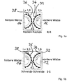
- a back-to-back and a cut-to-cut operating mode (RR and SS operating mode, respectively) are described with reference to FIG Figure 1a and Figure 1b briefly explained below.
- a first roller (front roller) 12 and a second roller (rear roller) 14 are each rotatably mounted about their axis of rotation, the two axes of rotation running parallel to each other and between the two rollers 12, 14 a gap 13 for receiving the ground material.
- the circumferential surface of the front roller 12 is provided with a plurality of elevations (corrugations), each corrugation having a cutting surface (corrugating blade) 32 and a back surface (corrugated back) 34.
- the corrugated ridges are each aligned approximately tangentially to the outer surface of the front roller 12.
- the corrugated cutting edges 32 are approximately perpendicular to the jacket surface of the front roller 12. The same applies accordingly to the corrugating cutting edges 36 and the corrugated back 38 of the rear roller 14.
- the two rollers are driven so that they rotate at opposite speeds. This has the effect that the corrugation of the front roller 12 and the corrugation of the rear roller 14 in the region of the gap 13 move in the transport direction of the ground material (for example from top to bottom).
- the front roller is that roller in which the rear surface of each corrugation, viewed in the direction of movement of the respective corrugation, is in front of the cutting surface of the respective corrugation. That is, in the case of the front roller, the rear surface and then the cutting surface of the corrugation always enter the gap 13 first. In other words, in the front roller, the back surface of a corrugation is forward in the direction of movement and the cutting surface of the corrugation is behind. In the case of the rear roller, on the other hand, the cutting surface of a corrugation is in the front in the direction of movement and the rear surface of the corrugation is behind. In other words: the corrugated cutting edges 32 of the front roller 12 are each facing backwards, while the corrugating cutting edges 36 of the rear roller 14 are each facing forward.
- a change from an RR mode to an SS mode can in principle be achieved in two different ways.
- One possibility is to make the rear roller 14 rotate faster than the front roller 14 in the SS mode.
- Such a change in the speeds is generally not easy to achieve in the roller mills customary today, since the front and rear rollers are controlled by a common motor a common transmission can be driven.
- the transmission usually has little or no setting options.
- the speed ratio between the rear and front rollers is fixed.
- the change from RR to SS mode succeeds in that the two rollers 12, 14 are removed from their respective bearings with the motor at a standstill, then rotated 180 ° about their respective suitable transverse axis and in this rotated position back into their respective storage used to be stored.
- the front roller 12 thus becomes the new rear roller 12 and the rear roller 14 becomes the new front roller 14.
- the US 8,113,447 B1 relates to a process for grinding grain, but it also shows a roller frame, with all four possible operating modes (cutting-cutting, cutting-back, back-cutting, back-back) being possible for the process.
- all four possible operating modes cutting-cutting, cutting-back, back-cutting, back-back
- a method and not Regarding roller mill it cannot be deduced from the naming of the four possible operating modes that one and the same roller mill should control the respective operating modes.
- it is about optimizing the speed difference to maximize the oil yield achieved by the method, whereby it is stated that a maximum oil yield is obtained when the speed difference is in the range of 1.1: 1 and 1.4: 1 and in particular 1 , 3: 1.
- the US 8,480,019 B1 relates to a roller for use in processing grain. It also discloses a corresponding arrangement with two rollers (see there Figure 2 ).
- the cutting-cutting or spine-spine operating modes are not discussed in more detail there. It is only stated that one roller should rotate between 10 and 200% faster than the other roller. For those in there Figure 2 The arrangement shown, this means that it remains within the stated range in any case with back-to-back operation if the left roller is the faster roller. Accordingly, it remains with the cutting-cutting operation if the right roller is the faster.
- the WO 2009/067828 A1 discloses a roller mill which can optionally be equipped with corrugated rollers. It is stated, among other things, that the speed of the first grinding roller and the speed of the second grinding roller can be set independently of one another.
- the above-mentioned roller mill in the commercial school Im Hoppenlau in Stuttgart already provides that the change during operation by changing the speed of the first corrugated roller and / or the speed of the second corrugated roller is changed.
- the drive mechanism of the roller frame is designed so that the speed of the first corrugating roller and / or the speed of the second corrugating roller is possible during operation, that is, while both rollers are rotating normally. There is thus no need to stop the rollers and turn them by 180 ° in order to switch from S-S mode to R-R mode or vice versa.
- the invention is based on the object of lowering the manufacturing and operating costs of the roller mill without restricting functionality.
- the invention provides that the first electrical machine and the second electrical machine have different power ratings. For example, for many applications (for example grinding grain) it can be sufficient if the electrical machine for driving the rear roller has a lower rated power than the electrical machine for driving the front roller. Since motors with a lower nominal power are more cost-effective than comparable motors with a higher nominal power, the manufacturing costs can be reduced. Furthermore, the energy consumption of motors with a lower rated power is lower, so that there is also a reduction in operating costs.
- the ratio of the rated powers of the two electrical machines can be in the range between 1: 1.2 and 1: 5, for example. It is preferably in the range from 1: 2 to 1: 4. This achieves a good compromise between manufacturing costs on the one hand and versatility in use on the other.
- the electrical machine that drives the front corrugated roller has the higher nominal power.
- R-R mode the front roller is the faster of the two corrugated rollers.
- S-S mode the rear roller is the faster, but even in S-S mode, relatively low power is sufficient to drive the rear roller, since relatively low speeds are typically selected in S-S mode.
- a first frequency converter is assigned to the first electrical machine and a second frequency converter is assigned to the second electrical machine.
- the first electrical machine can be connected to an electrical voltage source via the first frequency converter.
- the second electrical machine can be connected to a second voltage source via the second frequency converter.
- the first and second electrical machines are preferably each connected to the same voltage source, for example to a private or public power grid, via the respective frequency converter.
- the voltage source can be an AC voltage source or a DC voltage source.
- the frequency of the voltage supplied by the AC voltage source can be between 20 Hz and 100 Hz, for example.
- Power supply networks generally supply an alternating voltage with an effective voltage of 110 V (for example in the USA) or 220 V (for example in Europe);
- the first and second frequency converters are advantageously suitable for connection to such an alternating voltage network.
- the Control by controlling the first or second frequency converter, the Control the output frequency of the frequency converter concerned and thus the speed of the first or second electrical machine.
- the speed of the first or second electrical machine is identical to the frequency of the output voltage (output frequency) of the first or second frequency converter.
- a first or a second control unit can be provided to control the first or second frequency converter.
- the frequency of the output voltage of the first or second frequency converter can be set by means of the first or second control unit.
- the first and second control units preferably have an operating unit, for example in the form of a rotary knob, for setting the desired output frequency.
- the first and the second control unit can have a common housing.
- one of the two electrical machines is operated as a motor and the other as a generator.
- This case can occur if the faster of the two rollers drives the slower one by frictional engagement and / or frictional engagement via the grist between the two rollers so strongly that the slower roller supplies a net electrical power that can be fed into the power grid or directly back into the electric machine of the faster roller flows.
- the case can also arise that the slower roller is driven partly via the electrical machine assigned to it and partly via frictional engagement and / or frictional engagement with the faster roller.
- the energy generated by the electrical machine operated as a generator is at least partially used to drive the electrical machine operated as a motor.
- This can be implemented, for example, in that the first electrical machine and the second electrical machine are coupled to one another via a power coupler.
- the first corrugated roller and the second corrugated roller have the same roller diameter. This means that the roller mill is equally suitable for both the RR mode and the SS mode.
- the first and the second corrugated roller are preferably identical in construction. This simplifies the manufacture, maintenance and, if necessary, repair of the roller frame.
- the ratio of the speed of the first roller and the speed of the second roller can be varied in the range of 7: 1 and 1: 4.5. This area is considered to be sufficiently large to meet the current requirements with regard to different grist and different required properties of the meal or flour produced.
- a stepless change in a differential speed and a corrugating action number can be brought about.
- a continuously adjustable first or second operating unit is provided for setting the speed of the first corrugating roller and / or for setting the speed of the second corrugating roller.
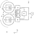
- FIG 2 shows schematically an example of a roller frame 10 with a first corrugated roller (first roller) 12 and a second corrugated roller (second roller) 14.
- the first roller 12 has a multiplicity of first corrugated blades 32 and first corrugated ridges 34.
- the second roller 14 has a plurality of second corrugated cutting edges 36 and second corrugated ridges 38.
- the roller mill 10 is designed to be operated either in a cutting-edge operating mode or in a back-and-back operating mode. In In the SS mode, the first cutting edges 32 and the second cutting edges 36 are brought closer to one another. In the RR mode of operation, the first ridges 34 and the second ridges 38 are brought closer to one another.
- a change between the SS operating mode and the RR operating mode can take place during ongoing operation by changing the speed of the first roller 12 and / or by changing the speed of the second roller 14.
- the first roller 12 operated as the front roller and the second roller 14 as the rear roller.
- the roller mill 10 comprises a first electrical machine 16 and a second electrical machine 18.
- the first roller 12 is mechanically and / or electromagnetically coupled or can be coupled to the first electrical machine 16, so that the first electrical machine generates a torque (in the example parallel to Y-axis, which is perpendicular to the plane of the drawing) can exert on the first roller 12 in order to cause a rotation of the first roller 12 about its axis of rotation (in the example parallel to the Y-axis).
- the second electrical machine 18 is mechanically or electromagnetically coupled or can be coupled to the second roller 14 and is thus able to exert a torque (in the example parallel to the Y-axis) on the second roller 14 in order to rotate the second roller 14 about it To cause rotation axis (in the example parallel to the Y-axis).
- the first roller 12 and the second roller 14 are operated in opposite directions. That is, the rotation speed vector of the second roller 14 is opposite to the rotation speed vector of the first roller 12.
- the rotational speed vector of the first roller 12 points against the Y direction (out of the plane of the drawing), while the rotational speed vector of the second roller 14 points in the positive Y direction (into the plane of the drawing).
- the two electrical machines 16, 18 can each be an alternating current, a three-phase or a direct current motor, for example.
- the maximum power (or the nominal power) of the first electric machine 16 is higher than the maximum power or the nominal power of the second electric machine 18.
- the maximum speed or the nominal speed of the first electric machine 16 is higher than the maximum speed or the nominal speed of the second electrical machine 18.
- the maximum power and / or the maximum speed of the first machine 16 is usually required in the RR mode.
- the maximum power and / or the maximum speed of the second electrical machine 18 is usually required in SS mode and is less than the maximum power or speed required by the first machine 16.
- the first electrical machine 16 has a nominal power of 7.5 kW and a maximum speed of 1000 revolutions per minute
- the second electrical machine 18 has a nominal power of 2.2 kW and a maximum speed of 200 revolutions per minute.
- the first electrical machine 16 is connected or can be connected to a voltage source 26, for example an alternating current source, via a first frequency converter 20.
- the second electrical machine 18 is connected or can be connected to the voltage source 26 via a second frequency converter 22.
- the voltage source 26 can, for example, be a connection point to an extensive power supply network.
- the voltage source 26 can provide an alternating voltage of 220 V and 50 Hz, for example.
- Each of the two frequency converters 20, 22 uses the input voltage applied to its voltage input (for example the supply voltage supplied by the voltage source 26) to provide an output voltage with a suitable voltage output (which is connected to the first or second electrical machine 16, 18) To generate effective value and suitable frequency.
- the first frequency converter 20 thus supplies the first electrical machine 16 with an alternating voltage with a first frequency F1.
- the second frequency converter 22 supplies the second electrical machine 18 with an alternating voltage with a second frequency F2.
- the roller mill 10 further comprises a first control unit 40 for setting the output frequency F1 generated by the first frequency converter 20 and a second control unit 42 for setting the output frequency F2 generated by the second frequency converter 22.
- the first control unit 40 and the second control unit 42 can each be coupled mechanically, electrically, electromagnetically or electromechanically to the corresponding first or second frequency converter 20, 22.
- the two control units 40, 42 can each have a user and / or a computer interface 44 or 46 in order to enable a user or computer to set the output frequencies F1 and F2 of the frequency converters 20, 22.
- the first frequency converter 20 and the first electrical machine 16 connected to it have a transmission ratio of 1: 1.
- the output voltage of the first frequency converter 20 with frequency F1 generates a corresponding rotation of the first roller 12 with the same frequency, that is to say rotational speed, F1.
- the control units 40, 42 set the speeds D1 and D2 of the first and second rollers 12, 14 individually, in particular during operation, that is, while the rollers 12, 14 are rotating and while they are being supplied with energy by the frequency converters 20, 22. In particular, it is possible in this way to change from an SS mode (in which D2> D1) to an RR mode (in which D1> D2) and vice versa during operation.
- the faster rotating roller transfers energy to the ground material (e.g. grain) through mechanical contact with the slower rotating roller slower roller and thus partially or even completely drives it.
- the electric machine of the slower roller acts as an electric generator.
- the electrical machine acting as a generator (either the first electrical machine 16 or the second electrical machine 18) then supplies electrical energy to the frequency converter (20 or 22) connected to it. In a simple embodiment (not shown), this energy flows at least largely back into the voltage source 26, for example into a power supply network.
- a power coupler 24 is provided, which electrically couples the two frequency converters 20, 22 to one another and thus returns the generated electrical energy to the frequency converter (20 or 22) of the faster rotating roller (12 or 14).
- the voltage source 26 is thus relieved.
- a suitable power coupler is offered by the company Eaton (formerly Moeller), for example. When using the power coupler 24, the speeds of the two rollers 12, 14 can be changed almost arbitrarily and independently of one another, without any major loss of energy.
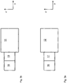
- the rollers 12, 14 are driven by the respective electrical machine 16 or 18 via a first gear 17 or a second gear 19.
- the two transmissions 17 and 19 can each be a transmission with a fixed (that is, non-adjustable) transmission ratio, since the speeds of the first and second electrical machines 16, 18 can be varied. Manual transmissions can be dispensed with without any significant disadvantages.
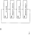
- FIG. 10 illustrates a method 200 of operating a rolling mill, for example, rolling mill 10 of FIG Figure 2 .
- the roller mill is operated in an RR mode. That is, the front roller rotates faster than the rear roller (D1 ⁇ D2).
- the speed D1 of the front roller is reduced and the speed D2 of the rear roller is increased. This can be done during operation by reducing the speed of the first electrical machine and increasing the speed of the second electrical machine.
- the rear roller rotates faster than the front roller. That is, D1 ⁇ D2.
- the rolling mill is now operated in an SS mode.
- phase 208 the speed D1 of the first roller is increased again and the speed D2 of the second roller is reduced again. During operation, this is achieved similarly to phase 204 by increasing the speed of the first electrical machine and reducing the speed of the second electrical machine.
- the rolling mill is now in an RR mode again.
Description
Die Erfindung betrifft einen Walzenstuhl gemäß dem Oberbegriff des Anspruchs 1. Ein derartiger Walzenstuhl war bereits vor dem Prioritätstag der vorliegenden Anmeldung zu Ausbildungszwecken in der gewerblichen Schule Im Hoppenlau in Stuttgart im Einsatz.The invention relates to a roller mill according to the preamble of
Derartige Walzenstühle werden in Mühlen zum Mahlen von Mahlgut pflanzlichen Ursprungs verwendet, zum Beispiel zum Mahlen von Getreide (zum Beispiel Weizen, Gerste, Roggen, Hafer, Dinkel) oder anderer Erzeugnisse (zum Beispiel Mais, Maniok, Kakaobohnen, Kaffeebohnen, Nüsse). Ein Rücken-Rücken- und ein Schneide-Schneide-Betriebsmodus (R-R- beziehungsweise S-S-Betriebsmodus) werden unter Bezugnahme auf
Als vordere Walze wird diejenige Walze bezeichnet, bei der die Rückfläche eines jeden Riffels in Bewegungsrichtung des betreffenden Riffels betrachtet der Schneidfläche des betreffenden Riffels vorgelagert ist. Das heißt, bei der vorderen Walze tritt stets zunächst die Rückfläche und dann die Schneidfläche des Riffels in den Spalt 13 ein. In anderen Worten liegt bei der vorderen Walze die Rückfläche eines Riffels in Bewegungsrichtung vorn und die Schneidfläche des Riffels liegt hinten. Bei der hinteren Walze hingegen liegt die Schneidfläche eines Riffels in Bewegungsrichtung vorn und die Rückfläche des Riffels liegt hinten. In anderen Worten: die Riffelschneiden 32 der vorderen Walze 12 sind jeweils nach hinten gewandt, während die Riffelschneiden 36 der hinteren Walze 14 jeweils nach vorne gewandt sind.The front roller is that roller in which the rear surface of each corrugation, viewed in the direction of movement of the respective corrugation, is in front of the cutting surface of the respective corrugation. That is, in the case of the front roller, the rear surface and then the cutting surface of the corrugation always enter the
Ein Wechsel von einem R-R-Modus in einen S-S-Modus lässt sich prinzipiell auf zwei unterschiedliche Weisen erreichen. Eine Möglichkeit besteht darin, dafür zu sorgen, dass sich die hintere Walze 14 im S-S-Modus schneller als die vordere Walze 14 dreht. Dies ist in
Die
Die
Die
Um einen komfortablen und schnellen Wechsel zwischen dem S-S-Modus und dem R-R-Modus zu erlauben, ist bei dem eingangs erwähnten Walzenstuhl in der gewerblichen Schule Im Hoppenlau in Stuttgart bereits vorgesehen, dass der Wechsel im laufenden Betrieb durch eine Veränderung der Drehzahl der ersten Riffelwalze und/oder eine Veränderung der Drehzahl der zweiten Riffelwalze erfolgt. In anderen Worten wird der Antriebsmechanismus des Walzenstuhls so gestaltet, dass die Drehzahl der ersten Riffelwalze und/oder die Drehzahl der zweiten Riffelwalze im laufenden Betrieb, das heißt, während sich beide Walzen normal drehen, möglich ist. Es entfällt somit das Erfordernis, die Walzen anzuhalten und um 180° zu drehen, um vom S-S-Modus in den R-R-Modus oder umgekehrt zu schalten.In order to allow a comfortable and quick change between the SS mode and the RR mode, the above-mentioned roller mill in the commercial school Im Hoppenlau in Stuttgart already provides that the change during operation by changing the speed of the first corrugated roller and / or the speed of the second corrugated roller is changed. In other words, the drive mechanism of the roller frame is designed so that the speed of the first corrugating roller and / or the speed of the second corrugating roller is possible during operation, that is, while both rollers are rotating normally. There is thus no need to stop the rollers and turn them by 180 ° in order to switch from S-S mode to R-R mode or vice versa.
Davon ausgehend liegt der Erfindung die Aufgabe zugrunde, die Herstellungs- und Betriebskosten des Walzenstuhls ohne Einschränkungen der Funktionalität zu senken. Zur Lösung dieser Aufgabe ist erfindungsgemäß vorgesehen, dass die erste elektrische Maschine und die zweite elektrische Maschine unterschiedliche Nennleistungen aufweisen. Zum Beispiel kann es für viele Anwendungen (zum Beispiel Mahlen von Getreide) genügen, wenn die elektrische Maschine zum Antreiben der hinteren Walze eine geringere Nennleistung aufweist als die elektrische Maschine zum Antreiben der vorderen Walze. Da Motoren mit geringerer Nennleistung kostengünstiger sind als vergleichbare Motoren mit höherer Nennleistung, lassen sich somit die Herstellungskosten senken. Weiterhin ist der Energieverbrauch von Motoren mit niedrigerer Nennleistung geringer, so dass sich auch eine Verringerung der Betriebskosten ergibt.On this basis, the invention is based on the object of lowering the manufacturing and operating costs of the roller mill without restricting functionality. To achieve this object, the invention provides that the first electrical machine and the second electrical machine have different power ratings. For example, for many applications (for example grinding grain) it can be sufficient if the electrical machine for driving the rear roller has a lower rated power than the electrical machine for driving the front roller. Since motors with a lower nominal power are more cost-effective than comparable motors with a higher nominal power, the manufacturing costs can be reduced. Furthermore, the energy consumption of motors with a lower rated power is lower, so that there is also a reduction in operating costs.
Das Verhältnis der Nennleistungen der beiden elektrischen Maschinen kann zum Beispiel im Bereich zwischen 1:1,2 und 1:5 liegen. Vorzugsweise liegt es im Bereich von 1:2 bis 1:4. Damit gelingt ein guter Kompromiss zwischen Herstellungskosten einerseits und Vielseitigkeit im Einsatz andererseits.The ratio of the rated powers of the two electrical machines can be in the range between 1: 1.2 and 1: 5, for example. It is preferably in the range from 1: 2 to 1: 4. This achieves a good compromise between manufacturing costs on the one hand and versatility in use on the other.
Insbesondere kann vorgesehen sein, dass diejenige elektrische Maschine die höhere Nennleistung aufweist, die die vordere Riffelwalze antreibt. Im R-R-Modus ist die vordere Walze die schnellere der beiden Riffelwalzen. Im S-S-Modus ist die hintere Walze die schnellere, doch genügt auch im S-S-Modus für den Antrieb der hinteren Walze eine relativ geringe Leistung, da im S-S-Modus typischerweise relativ geringe Drehzahlen gewählt werden.In particular, it can be provided that the electrical machine that drives the front corrugated roller has the higher nominal power. In R-R mode, the front roller is the faster of the two corrugated rollers. In S-S mode, the rear roller is the faster, but even in S-S mode, relatively low power is sufficient to drive the rear roller, since relatively low speeds are typically selected in S-S mode.
Gemäß einer Ausführungsform ist der ersten elektrischen Maschine ein erster Frequenzumrichter und der zweiten elektrischen Maschine ein zweiter Frequenzumrichter zugeordnet. Die erste elektrische Maschine kann über den ersten Frequenzumrichter an eine elektrische Spannungsquelle angeschlossen werden. Die zweite elektrische Maschine kann über den zweiten Frequenzumrichter an eine zweite Spannungsquelle angeschlossen werden. Vorzugsweise werden die erste und die zweite elektrische Maschine über den jeweiligen Frequenzumrichter jeweils an dieselbe Spannungsquelle, zum Beispiel an ein privates oder öffentliches Stromnetz, angeschlossen. Die Spannungsquelle kann eine Wechselspannungsquelle oder aber eine Gleichspannungsquelle sein. Die Frequenz der von der Wechselspannungsquelle gelieferten Spannung kann zum Beispiel zwischen 20 Hz und 100 Hz betragen. Stromversorgungsnetze liefern im Allgemeinen eine Wechselspannung mit einer Effektivspannung von 110 V (zum Beispiel in den USA) oder 220 V (zum Beispiel in Europa); vorteilhafterweise sind der erste und der zweite Frequenzumrichter für den Anschluss an ein derartiges Wechselspannungsnetz geeignet. Im Betrieb lässt sich durch Steuerung des ersten beziehungsweise zweiten Frequenzumrichters die Ausgangsfrequenz des betreffenden Frequenzumrichters und damit die Drehzahl der ersten beziehungsweise zweiten elektrischen Maschine steuern. Im einfachsten Fall ist die Drehzahl der ersten beziehungsweise zweiten elektrischen Maschine identisch mit der Frequenz der Ausgangsspannung (Ausgangsfrequenz) des ersten beziehungsweise zweiten Frequenzumrichters. Zur Steuerung des ersten beziehungsweise zweiten Frequenzumrichters kann eine erste beziehungsweise eine zweite Steuereinheit vorgesehen sein. Mittels der ersten beziehungsweise zweiten Steuereinheit lässt sich die Frequenz der Ausgangspannung des ersten beziehungsweise zweiten Frequenzumrichters einstellen. Die erste beziehungsweise zweite Steuereinheit weisen vorzugsweise eine Bedieneinheit, zum Beispiel in Form eines Drehknopfes, zum Einstellen der gewünschten Ausgangsfrequenz auf. Die erste und die zweite Steuereinheit können ein gemeinsames Gehäuse aufweisen.According to one embodiment, a first frequency converter is assigned to the first electrical machine and a second frequency converter is assigned to the second electrical machine. The first electrical machine can be connected to an electrical voltage source via the first frequency converter. The second electrical machine can be connected to a second voltage source via the second frequency converter. The first and second electrical machines are preferably each connected to the same voltage source, for example to a private or public power grid, via the respective frequency converter. The voltage source can be an AC voltage source or a DC voltage source. The frequency of the voltage supplied by the AC voltage source can be between 20 Hz and 100 Hz, for example. Power supply networks generally supply an alternating voltage with an effective voltage of 110 V (for example in the USA) or 220 V (for example in Europe); The first and second frequency converters are advantageously suitable for connection to such an alternating voltage network. During operation, by controlling the first or second frequency converter, the Control the output frequency of the frequency converter concerned and thus the speed of the first or second electrical machine. In the simplest case, the speed of the first or second electrical machine is identical to the frequency of the output voltage (output frequency) of the first or second frequency converter. A first or a second control unit can be provided to control the first or second frequency converter. The frequency of the output voltage of the first or second frequency converter can be set by means of the first or second control unit. The first and second control units preferably have an operating unit, for example in the form of a rotary knob, for setting the desired output frequency. The first and the second control unit can have a common housing.
Während des Betriebs ist es möglich, dass eine der beiden elektrischen Maschinen als Motor und die andere als Generator betrieben wird. Dieser Fall kann auftreten, wenn die schnellere der beiden Walzen die langsamere durch Kraftschluss und/oder Reibschluss über das Mahlgut zwischen den beiden Walzen derart stark antreibt, dass die langsamere Walze eine elektrische Nettoleistung liefert, die zum Beispiel in das Stromnetz oder direkt zurück in die elektrische Maschine der schnelleren Walze fließt. Es kann aber auch der Fall auftreten, dass die langsamere Walze zum Teil über die ihr zugeordnete elektrische Maschine und zum restlichen Teil über Kraftschluss und/oder Reibschluss mit der schnelleren Walze angetrieben wird.During operation, it is possible that one of the two electrical machines is operated as a motor and the other as a generator. This case can occur if the faster of the two rollers drives the slower one by frictional engagement and / or frictional engagement via the grist between the two rollers so strongly that the slower roller supplies a net electrical power that can be fed into the power grid or directly back into the electric machine of the faster roller flows. However, the case can also arise that the slower roller is driven partly via the electrical machine assigned to it and partly via frictional engagement and / or frictional engagement with the faster roller.
Gemäß einer Ausführungsform wird die von der als Generator betriebenen elektrischen Maschine erzeugte Energie zumindest teilweise zum Antrieb der als Motor betriebenen elektrischen Maschine verwendet. Dies kann zum Beispiel dadurch realisiert werden, dass die erste elektrische Maschine und die zweite elektrische Maschine über einen Leistungskoppler miteinander gekoppelt werden.According to one embodiment, the energy generated by the electrical machine operated as a generator is at least partially used to drive the electrical machine operated as a motor. This can be implemented, for example, in that the first electrical machine and the second electrical machine are coupled to one another via a power coupler.
Gemäß einer Ausführungsform haben die erste Riffelwalze und die zweite Riffelwalze den gleichen Walzendurchmesser. Damit ist der Walzenstuhl gleichermaßen für den R-R-Modus wie den S-S-Modus geeignet. Vorzugsweise sind die erste und die zweite Riffelwalze baugleich. Dies vereinfacht die Herstellung, Wartung und gegebenenfalls Reparatur des Walzenstuhls.According to one embodiment, the first corrugated roller and the second corrugated roller have the same roller diameter. This means that the roller mill is equally suitable for both the RR mode and the SS mode. The first and the second corrugated roller are preferably identical in construction. This simplifies the manufacture, maintenance and, if necessary, repair of the roller frame.
Es kann vorgesehen sein, dass das Verhältnis der Drehzahl der ersten Walze und der Drehzahl der zweiten Walze im Bereich von 7:1 und 1:4,5 variierbar ist. Dieser Bereich wird als ausreichend groß erachtet, um den gängigen Anforderungen im Hinblick auf unterschiedliches Mahlgut und unterschiedlichen verlangten Eigenschaften des erzeugten Schrots oder Mehls zu genügen.It can be provided that the ratio of the speed of the first roller and the speed of the second roller can be varied in the range of 7: 1 and 1: 4.5. This area is considered to be sufficiently large to meet the current requirements with regard to different grist and different required properties of the meal or flour produced.
Gemäß einer Ausführungsform lässt sich durch die Veränderung der Drehzahl der ersten Riffelwalze und/oder die Veränderung der Drehzahl der zweiten Riffelwalze eine stufenlose Veränderung einer Differentialgeschwindigkeit und einer Riffeleinwirkzahl hervorrufen. Dies gelingt zum Beispiel dadurch, dass zur Einstellung der Drehzahl der ersten Riffelwalze und/oder zur Einstellung der Drehzahl der zweiten Riffelwalze eine stufenlos einstellbare erste beziehungsweise zweite Bedieneinheit zur Verfügung gestellt wird.According to one embodiment, by changing the speed of the first corrugating roller and / or changing the speed of the second corrugating roller, a stepless change in a differential speed and a corrugating action number can be brought about. This is achieved, for example, in that a continuously adjustable first or second operating unit is provided for setting the speed of the first corrugating roller and / or for setting the speed of the second corrugating roller.
Die Erfindung wird nachfolgend unter Bezugnahme auf die beigefügten Zeichnungen näher erläutert. Dabei bezeichnen gleiche Bezugszeichen gleiche oder ähnliche Komponenten.
-
Figur 1a und Figur 1b veranschaulichen einen R-R-Modus und einen S-S-Modus. -
Figur 2 -
Figur 3a und Figur 3b zeigen jeweils schematisch ein Ausführungsbeispiel mit einem Getriebe. -
Figur 4 zeigt ein Flussdiagramm eines Ausführungsbeispiels eines Verfahrens zum Betreiben eines Walzenstuhls. -
Figur 5
-
Figure 1a and Figure 1b illustrate an RR mode and an SS mode. -
Figure 2 shows schematically an embodiment of a roller mill. -
Figure 3a and Figure 3b each show schematically an embodiment with a transmission. -
Figure 4 FIG. 3 shows a flow diagram of an exemplary embodiment of a method for operating a roller mill. -
Figure 5 shows a table with examples of typical transmission ratios and flute positions of a grain mill.
Der Walzenstuhl 10 umfasst eine erste elektrische Maschine 16 und eine zweite elektrische Maschine 18. Die erste Walze 12 ist mit der ersten elektrischen Maschine 16 mechanisch und/oder elektromagnetisch gekoppelt oder koppelbar, so dass die erste elektrische Maschine ein Drehmoment (in dem Beispiel parallel zur Y-Achse, die hier senkrecht zur Zeichenebene steht) auf die erste Walze 12 ausüben kann, um eine Rotation der ersten Walze 12 um ihre Drehachse (in dem Beispiel parallel zur Y-Achse) zu bewirken. Die zweite elektrische Maschine 18 ist mit der zweiten Walze 14 mechanisch oder elektromagnetisch gekoppelt oder koppelbar und damit im stande, auf die zweite Walze 14 ein Drehmoment (in dem Beispiel parallel zur Y-Achse) auszuüben, um eine Rotation der zweiten Walze 14 um ihre Drehachse (in dem Beispiel parallel zur Y-Achse) zu bewirken. Im gewöhnlichen Mahlbetrieb werden die erste Walze 12 und die zweite Walze 14 gegenläufig betrieben. Das heißt, der Rotationsgeschwindigkeitsvektor der zweiten Walze 14 ist dem Rotationsgeschwindigkeitsvektor der ersten Walze 12 entgegengerichtet. In dem Beispiel zeigt der Rotationsgeschwindigkeitsvektor der ersten Walze 12 gegen die Y-Richtung (aus der Zeichenebene heraus), während der Rotationsgeschwindigkeitsvektor der zweiten Walze 14 in die positive Y-Richtung (in die Zeichenebene hinein) zeigt. Die beiden elektrischen Maschinen 16, 18 können zum Beispiel jeweils ein Wechselstrom-, ein Drehstrom- oder ein Gleichstrommotor sein. Die Maximalleistung (oder die Nennleistung) der ersten elektrischen Maschine 16 ist höher als die maximale Leistung beziehungsweise die Nennleistung der zweiten elektrischen Maschine 18. Des Weiteren ist die maximale Drehzahl oder die Nenndrehzahl der ersten elektrischen Maschine 16 höher als die maximale Drehzahl beziehungsweise die Nenndrehzahl der zweiten elektrischen Maschine 18. Die maximale Leistung und/oder die maximale Drehzahl der ersten Maschine 16 wird gewöhnlicherweise im R-R-Modus verlangt. Die maximale Leistung und/oder die maximale Drehzahl der zweiten elektrischen Maschine 18 wird gewöhnlicherweise im S-S-Modus verlangt und ist geringer als die maximal von der ersten Maschine 16 verlangte Leistung beziehungsweise Drehzahl. In dem Beispiel hat die erste elektrische Maschine 16 eine Nennleistung von 7,5 kW und eine maximale Drehzahl von 1000 Umdrehungen pro Minute, während die zweite elektrische Maschine 18 eine Nennleistung von 2,2 kW und eine maximale Drehzahl von 200 Umdrehungen pro Minute besitzt.The
Die erste elektrische Maschine 16 ist über einen ersten Frequenzumrichter 20 an eine Spannungsquelle 26, zum Beispiel eine Wechselstromquelle, angeschlossen oder anschließbar. Die zweite elektrische Maschine 18 ist über einen zweiten Frequenzumrichter 22 an die Spannungsquelle 26 angeschlossen oder anschließbar. Die Spannungsquelle 26 kann zum Beispiel ein Anschlusspunkt an ein ausgedehntes Stromversorgungsnetz sein. Die Spannungsquelle 26 kann zum Beispiel eine Wechselspannung mit 220 V und 50 Hz bereitstellen. Jeder der beiden Frequenzumrichter 20, 22 nutzt die an seinem Spannungseingang anliegende Eingangsspannung (zum Beispiel die von der Spannungsquelle 26 gelieferte Versorgungsspannung), um an seinem Spannungsausgang (der mit der ersten beziehungsweise zweiten elektrischen Maschine 16, 18 verbunden ist), eine Ausgangsspannung mit geeignetem Effektivwert und geeigneter Frequenz zu erzeugen. Der erste Frequenzumrichter 20 liefert der ersten elektrischen Maschine 16 somit eine Wechselspannung mit einer ersten Frequenz F1. Der zweite Frequenzumrichter 22 liefert der zweiten elektrischen Maschine 18 eine Wechselspannung mit einer zweiten Frequenz F2.The first
Der Walzenstuhl 10 umfasst weiter eine erste Steuereinheit 40 zum Einstellen der vom ersten Frequenzumrichter 20 erzeugten Ausgangsfrequenz F1 sowie eine zweite Steuereinheit 42 zum Einstellen der vom zweiten Frequenzumrichter 22 erzeugten Ausgangsfrequenz F2. Die erste Steuereinheit 40 und die zweite Steuereinheit 42 können jeweils mechanisch, elektrisch, elektromagnetisch oder elektromechanisch mit dem entsprechenden ersten beziehungsweise zweiten Frequenzumrichter 20, 22 gekoppelt sein. Die beiden Steuereinheiten 40, 42 können jeweils eine Benutzer- und/oder eine Computerschnittstelle 44 beziehungsweise 46 aufweisen, um es einem Nutzer oder Computer zu ermöglichen, die Ausgangsfrequenzen F1 und F2 der Frequenzumrichter 20, 22 einzustellen. Der erste Frequenzumrichter 20 und die an ihn angeschlossene erste elektrische Maschine 16 haben in einer einfachsten Ausführungsform ein Übersetzungsverhältnis von 1:1. In diesem Fall erzeugt die Ausgangsspannung des ersten Frequenzumrichters 20 mit Frequenz F1 eine entsprechende Rotation der ersten Walze 12 mit derselben Frequenz, das heißt Drehgeschwindigkeit, F1. Dasselbe gilt entsprechend für den zweiten Frequenzumrichter 22 und die an ihn angeschlossene zweite elektrische Maschine 18. Ausgangsfrequenzen F1 = 1000 Hz und F2 = 200 Hz können somit Drehzahlen D1 = 1000 pro Minute beziehungsweise D2 = 200 pro Minute erzeugen. Mittels der Steuereinheiten 40, 42 lassen sich die Drehzahlen D1 und D2 der ersten beziehungsweise zweiten Walze 12, 14 individuell einstellen, insbesondere im laufenden Betrieb, das heißt, während sich die Walzen 12, 14 drehen und während sie von den Frequenzumrichtern 20, 22 mit Energie versorgt werden. Insbesondere gelingt auf die Weise ein Wechsel von einem S-S-Modus (in welchem D2 > D1 ist) in einen R-R-Modus (in welchem D1 > D2 ist) und umgekehrt im laufenden Betrieb.The
Wenn eine der beiden Walzen 12, 14 schneller als die andere rotiert (also wenn D1 > D2 oder D2 > D1 ist), überträgt die schneller rotierende Walze durch mechanischen Kontakt mit der langsamer rotierenden Walze über das Mahlgut (zum Beispiel Getreide) Energie auf die langsamere Walze und treibt sie somit teilweise oder sogar vollständig an. In diesem Fall verhält sich die elektrische Maschine der langsameren Walze als elektrischer Generator. Die sich als Generator verhaltende elektrische Maschine (entweder die erste elektrische Maschine 16 oder die zweite elektrische Maschine 18) liefert dann elektrische Energie an den mit ihr verbundenen Frequenzumrichter (20 oder 22). In einer einfachen Ausführungsform (nicht dargestellt) fließt diese Energie zumindest größtenteils zurück in die Spannungsquelle 26, zum Beispiel in ein Stromversorgungsnetz. In dem gezeigten Beispiel hingegen ist ein Leistungskoppler 24 vorgesehen, der die beiden Frequenzumrichter 20, 22 miteinander elektrisch koppelt und damit die erzeugte elektrische Energie an den Frequenzumrichter (20 oder 22) der schneller rotierenden Walze (12 oder 14) zurückführt. Die Spannungsquelle 26 wird damit entlastet. Ein geeigneter Leistungskoppler wird zum Beispiel von dem Unternehmen Eaton (ehemals Moeller) angeboten. Bei Einsatz des Leistungskopplers 24 können die Drehzahlen der beiden Walzen 12, 14 nahezu beliebig und unabhängig voneinander verändert werden, ohne dass Energie in größerem Maß verloren geht.If one of the two
Bei der in
Das Flussdiagramm in
In der Tabelle in
- 1010
- WalzenstuhlRoller mill
- 1212
- erste Riffelwalzefirst corrugated roller
- 1313th
- Spaltgap
- 1414th
- zweite Riffelwalzesecond corrugated roller
- 1616
- erste elektrische Maschinefirst electric machine
- 1717th
- erstes Getriebefirst gear
- 1818th
- zweite elektrische Maschinesecond electric machine
- 1919th
- zweites Getriebesecond gear
- 2020th
- erster Frequenzumrichterfirst frequency converter
- 2222nd
- zweiter Frequenzumrichtersecond frequency converter
- 2424
- LeistungskopplerPower coupler
- 2626th
- SpannungsquelleVoltage source
- 3232
- erste Riffelschneidefirst serrated edge
- 3434
- erster Riffelrückenfirst corrugated back
- 3636
- zweite Riffelschneidesecond serrated edge
- 3838
- zweiter Riffelrückensecond corrugated back
- 4040
- erste Steuereinheitfirst control unit
- 4242
- zweite Steuereinheitsecond control unit
- 4444
- erste Benutzer- und/oder Computerschnittstellefirst user and / or computer interface
- 4646
- zweite Benutzer- und/oder Computerschnittstellesecond user and / or computer interface
- 200200
- VerfahrenProcedure
- 202202
- erste Phasefirst phase
- 204204
- zweite Phasesecond phase
- 206206
- dritte Phasethird phase
- 208208
- vierte Phasefourth phase
Claims (9)
- Roll frame (10) having a first corrugating roll (12) which has a multiplicity of first corrugating edges (32) and first corrugating backs (34), having a second corrugating roll (14) which has a multiplicity of second corrugating edges (36) and second corrugating backs (38), having a first electric machine (16) for driving the first corrugating roll and a second electric machine (18) for driving the second corrugating roll, the roll frame being designed to be operated either in an edge/edge operating mode, in which the first edges and the second edges are brought closer to one another, or in a back/back operating mode, in which the first backs and the second backs are brought closer to one another, wherein a change between the edge/edge operating mode and the back/back operating mode takes place during running operation by way of a change in the rotational speed of the first corrugating roll and/or a change in the rotational speed of the second corrugating roll, characterized in that, the first electric machine (16) and the second electric machine (18) have different nominal outputs.
- Roll frame according to Claim 1, characterized in that the ratio of the nominal outputs of the two electric machines lies in the range between 1:1.2 and 1:5 and preferably in the range from 1:2 to 1:4.
- Roll frame according to Claim 1 or 2, characterized in that that electric machine which drives the more rapid of the two corrugating rolls in the back/back operating mode has the higher nominal output.
- Roll frame according to one of the preceding claims, characterized in that the first electric machine is assigned a first frequency converter (20), and in that the second electric machine is assigned a second frequency converter (22).
- Roll frame according to one of the preceding claims, characterized in that, of the two electric machines, one is operated as a motor and one is operated as a generator.
- Roll frame according to Claim 5, characterized in that the energy which is generated by the electric machine which is operated as a generator is used at least partially to drive the electric machine which is operated as a motor.
- Roll frame according to one of the preceding claims, characterized in that the first corrugating roll and the second corrugating roll have identical roll diameters.
- Roll frame according to one of the preceding claims, characterized in that the ratio of the rotational speed of the first roll and the rotational speed of the second roll can be varied in the range from 7:1 to 1:4.5.
- Roll frame according to one of the preceding claims, characterized in that an infinitely variable change in a differential speed and in a number of active corrugations is brought about by way of the change in the rotational speed of the first corrugating roll and/or the change in the rotational speed of the second corrugating roll.
Priority Applications (1)
| Application Number | Priority Date | Filing Date | Title |
|---|---|---|---|
| PL16182798T PL3127614T5 (en) | 2015-08-05 | 2016-08-04 | Roller mill with cutting cutting operating type and back back operating type |
Applications Claiming Priority (1)
| Application Number | Priority Date | Filing Date | Title |
|---|---|---|---|
| DE102015010157.9A DE102015010157A1 (en) | 2015-08-05 | 2015-08-05 | Roller mill with cutting-cutting mode and back-back mode |
Publications (4)
| Publication Number | Publication Date |
|---|---|
| EP3127614A2 EP3127614A2 (en) | 2017-02-08 |
| EP3127614A3 EP3127614A3 (en) | 2017-04-12 |
| EP3127614B1 EP3127614B1 (en) | 2018-04-18 |
| EP3127614B2 true EP3127614B2 (en) | 2020-11-18 |
Family
ID=56571249
Family Applications (1)
| Application Number | Title | Priority Date | Filing Date |
|---|---|---|---|
| EP16182798.5A Active EP3127614B2 (en) | 2015-08-05 | 2016-08-04 | Roller mill with cutting cutting operating type and back back operating type |
Country Status (4)
| Country | Link |
|---|---|
| EP (1) | EP3127614B2 (en) |
| DE (1) | DE102015010157A1 (en) |
| HU (1) | HUE038226T2 (en) |
| PL (1) | PL3127614T5 (en) |
Families Citing this family (2)
| Publication number | Priority date | Publication date | Assignee | Title |
|---|---|---|---|---|
| CN108787005A (en) * | 2018-07-03 | 2018-11-13 | 山东永平再生资源股份有限公司 | Waste materials pulverizer |
| CN109062134A (en) * | 2018-09-20 | 2018-12-21 | 安徽马钢设备检修有限公司 | A kind of novel four-roller is crushed electric-control system and control method |
Citations (5)
| Publication number | Priority date | Publication date | Assignee | Title |
|---|---|---|---|---|
| GB261753A (en) † | 1926-11-17 | 1927-12-01 | Richard Schermann | Improvements relating to the fine grinding of corn |
| DE859558C (en) † | 1949-06-04 | 1952-12-15 | Miag Vertriebs Gmbh | Connecting drive for the roller pairs of roller chairs |
| WO2009068921A1 (en) † | 2007-11-26 | 2009-06-04 | Kertesz Andras | High speed roller mill |
| WO2009067828A1 (en) † | 2007-11-27 | 2009-06-04 | Bühler AG | Cylinder mill |
| US8480019B1 (en) † | 2011-04-01 | 2013-07-09 | Shredlage, L.L.C. | Rolls for use with crop processor, system and method for processing crops |
Family Cites Families (6)
| Publication number | Priority date | Publication date | Assignee | Title |
|---|---|---|---|---|
| DE174199C (en) | ||||
| DE678825C (en) | 1938-05-29 | 1939-07-26 | Otto Moog Dr Ing | Method and device for setting roller frames with continuously variable gear ratios |
| DE824290C (en) | 1949-11-26 | 1951-12-10 | Zuendapp Werke G M B H | Grinding plant for grinding and grinding grain and grain products |
| DE1033995B (en) | 1953-12-05 | 1958-07-10 | Ludwig Schoeffel | Multi-roll mixer and grinder |
| DE102007061668A1 (en) | 2007-12-18 | 2009-06-25 | Bühler AG | roll mill |
| US8113447B1 (en) | 2009-11-05 | 2012-02-14 | Cereal Enterprises, Inc. | Corn milling process |
-
2015
- 2015-08-05 DE DE102015010157.9A patent/DE102015010157A1/en not_active Withdrawn
-
2016
- 2016-08-04 PL PL16182798T patent/PL3127614T5/en unknown
- 2016-08-04 HU HUE16182798A patent/HUE038226T2/en unknown
- 2016-08-04 EP EP16182798.5A patent/EP3127614B2/en active Active
Patent Citations (5)
| Publication number | Priority date | Publication date | Assignee | Title |
|---|---|---|---|---|
| GB261753A (en) † | 1926-11-17 | 1927-12-01 | Richard Schermann | Improvements relating to the fine grinding of corn |
| DE859558C (en) † | 1949-06-04 | 1952-12-15 | Miag Vertriebs Gmbh | Connecting drive for the roller pairs of roller chairs |
| WO2009068921A1 (en) † | 2007-11-26 | 2009-06-04 | Kertesz Andras | High speed roller mill |
| WO2009067828A1 (en) † | 2007-11-27 | 2009-06-04 | Bühler AG | Cylinder mill |
| US8480019B1 (en) † | 2011-04-01 | 2013-07-09 | Shredlage, L.L.C. | Rolls for use with crop processor, system and method for processing crops |
Non-Patent Citations (1)
| Title |
|---|
| behauptete offenkundige Vorbenutzung 'Hoppenlau' † |
Also Published As
| Publication number | Publication date |
|---|---|
| EP3127614A3 (en) | 2017-04-12 |
| HUE038226T2 (en) | 2018-10-29 |
| EP3127614A2 (en) | 2017-02-08 |
| DE102015010157A1 (en) | 2017-02-09 |
| EP3127614B1 (en) | 2018-04-18 |
| PL3127614T3 (en) | 2018-09-28 |
| PL3127614T5 (en) | 2021-08-30 |
Similar Documents
| Publication | Publication Date | Title |
|---|---|---|
| DE102013102603B4 (en) | Method for a black start of a power plant with multiple inverters connectable to an AC grid | |
| DE102007021089B3 (en) | Method for controlling parallel-connected backup power sources and device with parallel-connected backup power sources | |
| DE102012107043B4 (en) | Roller mill and method for comminuting regrind with a roller mill | |
| DE102008036784B4 (en) | Roller mill and method for comminution of regrind | |
| EP1212549B1 (en) | Drive | |
| DE102011087109B3 (en) | Apparatus and method for recovering energy from a fluid flow | |
| EP3127614B2 (en) | Roller mill with cutting cutting operating type and back back operating type | |
| WO2013143652A1 (en) | Drive device in a self-propelled construction machine and method for setting the speed ratio in such a drive device | |
| DE102018219944B4 (en) | Variable speed booster and associated control method | |
| EP1749576A2 (en) | Comminuting apparatus having a frequency controlled electric motor and an epicyclic gear mechanism | |
| WO2015169950A1 (en) | Roller mill and method for controlling a roller mill | |
| DE2409741C2 (en) | Device for cutting and / or creasing blanks from folded material | |
| EP2698207B1 (en) | Multi-area dual shaft cutting system | |
| EP3238337B1 (en) | Method for operation of a drive train | |
| DE102014210868A1 (en) | Device for power transmission and machine arrangement with it | |
| EP2848311A1 (en) | Blade for a shredding apparatus | |
| WO2019091679A1 (en) | Drive axle for an electrically driven work machine | |
| DE102014210869A1 (en) | Device for in particular power transmission | |
| EP3756260B1 (en) | Multichannel prl: power grid and method and system for providing a controlling power for regulating a power grid frequency of a power grid | |
| AT15388U1 (en) | Drive train and method for operating a drive train | |
| DE102020204326A1 (en) | Double motor unit for a flywheel mass storage device with non-linear overall performance characteristic | |
| EP1022845A2 (en) | Method and device for controling an electric motor of a document shredder | |
| DE102005022378A1 (en) | roll refiner | |
| DE102012201762A1 (en) | Wind power generator and blade mounting method | |
| EP3501093A1 (en) | Method for operating a system with drives which are mechanically coupled together and with a higher-level computer, and system |
Legal Events
| Date | Code | Title | Description |
|---|---|---|---|
| PUAI | Public reference made under article 153(3) epc to a published international application that has entered the european phase |
Free format text: ORIGINAL CODE: 0009012 |
|
| STAA | Information on the status of an ep patent application or granted ep patent |
Free format text: STATUS: THE APPLICATION HAS BEEN PUBLISHED |
|
| AK | Designated contracting states |
Kind code of ref document: A2 Designated state(s): AL AT BE BG CH CY CZ DE DK EE ES FI FR GB GR HR HU IE IS IT LI LT LU LV MC MK MT NL NO PL PT RO RS SE SI SK SM TR |
|
| AX | Request for extension of the european patent |
Extension state: BA ME |
|
| PUAL | Search report despatched |
Free format text: ORIGINAL CODE: 0009013 |
|
| AK | Designated contracting states |
Kind code of ref document: A3 Designated state(s): AL AT BE BG CH CY CZ DE DK EE ES FI FR GB GR HR HU IE IS IT LI LT LU LV MC MK MT NL NO PL PT RO RS SE SI SK SM TR |
|
| AX | Request for extension of the european patent |
Extension state: BA ME |
|
| RIC1 | Information provided on ipc code assigned before grant |
Ipc: B02C 4/08 20060101AFI20170309BHEP Ipc: B02C 4/42 20060101ALI20170309BHEP Ipc: B02C 9/02 20060101ALI20170309BHEP |
|
| STAA | Information on the status of an ep patent application or granted ep patent |
Free format text: STATUS: REQUEST FOR EXAMINATION WAS MADE |
|
| 17P | Request for examination filed |
Effective date: 20171011 |
|
| RBV | Designated contracting states (corrected) |
Designated state(s): AL AT BE BG CH CY CZ DE DK EE ES FI FR GB GR HR HU IE IS IT LI LT LU LV MC MK MT NL NO PL PT RO RS SE SI SK SM TR |
|
| GRAP | Despatch of communication of intention to grant a patent |
Free format text: ORIGINAL CODE: EPIDOSNIGR1 |
|
| STAA | Information on the status of an ep patent application or granted ep patent |
Free format text: STATUS: GRANT OF PATENT IS INTENDED |
|
| RIC1 | Information provided on ipc code assigned before grant |
Ipc: B02C 9/02 20060101ALI20171114BHEP Ipc: B02C 4/42 20060101ALI20171114BHEP Ipc: B02C 4/08 20060101AFI20171114BHEP |
|
| INTG | Intention to grant announced |
Effective date: 20171220 |
|
| GRAS | Grant fee paid |
Free format text: ORIGINAL CODE: EPIDOSNIGR3 |
|
| GRAA | (expected) grant |
Free format text: ORIGINAL CODE: 0009210 |
|
| STAA | Information on the status of an ep patent application or granted ep patent |
Free format text: STATUS: THE PATENT HAS BEEN GRANTED |
|
| AK | Designated contracting states |
Kind code of ref document: B1 Designated state(s): AL AT BE BG CH CY CZ DE DK EE ES FI FR GB GR HR HU IE IS IT LI LT LU LV MC MK MT NL NO PL PT RO RS SE SI SK SM TR |
|
| REG | Reference to a national code |
Ref country code: GB Ref legal event code: FG4D Free format text: NOT ENGLISH |
|
| REG | Reference to a national code |
Ref country code: CH Ref legal event code: EP |
|
| REG | Reference to a national code |
Ref country code: AT Ref legal event code: REF Ref document number: 989860 Country of ref document: AT Kind code of ref document: T Effective date: 20180515 |
|
| REG | Reference to a national code |
Ref country code: IE Ref legal event code: FG4D Free format text: LANGUAGE OF EP DOCUMENT: GERMAN |
|
| REG | Reference to a national code |
Ref country code: DE Ref legal event code: R096 Ref document number: 502016000910 Country of ref document: DE |
|
| REG | Reference to a national code |
Ref country code: NL Ref legal event code: MP Effective date: 20180418 |
|
| REG | Reference to a national code |
Ref country code: FR Ref legal event code: PLFP Year of fee payment: 3 |
|
| REG | Reference to a national code |
Ref country code: CH Ref legal event code: NV Representative=s name: RIEDERER HASLER AND PARTNER PATENTANWAELTE AG, CH |
|
| REG | Reference to a national code |
Ref country code: LT Ref legal event code: MG4D |
|
| PG25 | Lapsed in a contracting state [announced via postgrant information from national office to epo] |
Ref country code: NL Free format text: LAPSE BECAUSE OF FAILURE TO SUBMIT A TRANSLATION OF THE DESCRIPTION OR TO PAY THE FEE WITHIN THE PRESCRIBED TIME-LIMIT Effective date: 20180418 |
|
| REG | Reference to a national code |
Ref country code: HU Ref legal event code: AG4A Ref document number: E038226 Country of ref document: HU |
|
| PG25 | Lapsed in a contracting state [announced via postgrant information from national office to epo] |
Ref country code: ES Free format text: LAPSE BECAUSE OF FAILURE TO SUBMIT A TRANSLATION OF THE DESCRIPTION OR TO PAY THE FEE WITHIN THE PRESCRIBED TIME-LIMIT Effective date: 20180418 Ref country code: LT Free format text: LAPSE BECAUSE OF FAILURE TO SUBMIT A TRANSLATION OF THE DESCRIPTION OR TO PAY THE FEE WITHIN THE PRESCRIBED TIME-LIMIT Effective date: 20180418 Ref country code: NO Free format text: LAPSE BECAUSE OF FAILURE TO SUBMIT A TRANSLATION OF THE DESCRIPTION OR TO PAY THE FEE WITHIN THE PRESCRIBED TIME-LIMIT Effective date: 20180718 Ref country code: FI Free format text: LAPSE BECAUSE OF FAILURE TO SUBMIT A TRANSLATION OF THE DESCRIPTION OR TO PAY THE FEE WITHIN THE PRESCRIBED TIME-LIMIT Effective date: 20180418 Ref country code: BG Free format text: LAPSE BECAUSE OF FAILURE TO SUBMIT A TRANSLATION OF THE DESCRIPTION OR TO PAY THE FEE WITHIN THE PRESCRIBED TIME-LIMIT Effective date: 20180718 Ref country code: AL Free format text: LAPSE BECAUSE OF FAILURE TO SUBMIT A TRANSLATION OF THE DESCRIPTION OR TO PAY THE FEE WITHIN THE PRESCRIBED TIME-LIMIT Effective date: 20180418 Ref country code: SE Free format text: LAPSE BECAUSE OF FAILURE TO SUBMIT A TRANSLATION OF THE DESCRIPTION OR TO PAY THE FEE WITHIN THE PRESCRIBED TIME-LIMIT Effective date: 20180418 |
|
| PG25 | Lapsed in a contracting state [announced via postgrant information from national office to epo] |
Ref country code: GR Free format text: LAPSE BECAUSE OF FAILURE TO SUBMIT A TRANSLATION OF THE DESCRIPTION OR TO PAY THE FEE WITHIN THE PRESCRIBED TIME-LIMIT Effective date: 20180719 Ref country code: HR Free format text: LAPSE BECAUSE OF FAILURE TO SUBMIT A TRANSLATION OF THE DESCRIPTION OR TO PAY THE FEE WITHIN THE PRESCRIBED TIME-LIMIT Effective date: 20180418 Ref country code: RS Free format text: LAPSE BECAUSE OF FAILURE TO SUBMIT A TRANSLATION OF THE DESCRIPTION OR TO PAY THE FEE WITHIN THE PRESCRIBED TIME-LIMIT Effective date: 20180418 Ref country code: LV Free format text: LAPSE BECAUSE OF FAILURE TO SUBMIT A TRANSLATION OF THE DESCRIPTION OR TO PAY THE FEE WITHIN THE PRESCRIBED TIME-LIMIT Effective date: 20180418 |
|
| PG25 | Lapsed in a contracting state [announced via postgrant information from national office to epo] |
Ref country code: PT Free format text: LAPSE BECAUSE OF FAILURE TO SUBMIT A TRANSLATION OF THE DESCRIPTION OR TO PAY THE FEE WITHIN THE PRESCRIBED TIME-LIMIT Effective date: 20180820 |
|
| REG | Reference to a national code |
Ref country code: DE Ref legal event code: R026 Ref document number: 502016000910 Country of ref document: DE |
|
| PLBI | Opposition filed |
Free format text: ORIGINAL CODE: 0009260 |
|
| PLAX | Notice of opposition and request to file observation + time limit sent |
Free format text: ORIGINAL CODE: EPIDOSNOBS2 |
|
| PG25 | Lapsed in a contracting state [announced via postgrant information from national office to epo] |
Ref country code: RO Free format text: LAPSE BECAUSE OF FAILURE TO SUBMIT A TRANSLATION OF THE DESCRIPTION OR TO PAY THE FEE WITHIN THE PRESCRIBED TIME-LIMIT Effective date: 20180418 Ref country code: SK Free format text: LAPSE BECAUSE OF FAILURE TO SUBMIT A TRANSLATION OF THE DESCRIPTION OR TO PAY THE FEE WITHIN THE PRESCRIBED TIME-LIMIT Effective date: 20180418 Ref country code: DK Free format text: LAPSE BECAUSE OF FAILURE TO SUBMIT A TRANSLATION OF THE DESCRIPTION OR TO PAY THE FEE WITHIN THE PRESCRIBED TIME-LIMIT Effective date: 20180418 Ref country code: EE Free format text: LAPSE BECAUSE OF FAILURE TO SUBMIT A TRANSLATION OF THE DESCRIPTION OR TO PAY THE FEE WITHIN THE PRESCRIBED TIME-LIMIT Effective date: 20180418 |
|
| 26 | Opposition filed |
Opponent name: BAUERMEISTER ZERKLEINERUNGSTECHNIK GMBH Effective date: 20190118 Opponent name: RUECKERT MUEHLEN- UND ANLAGENTECHNIK GMBH & CO. KG Effective date: 20190117 Opponent name: BUEHLER AG Effective date: 20190118 |
|
| PG25 | Lapsed in a contracting state [announced via postgrant information from national office to epo] |
Ref country code: SM Free format text: LAPSE BECAUSE OF FAILURE TO SUBMIT A TRANSLATION OF THE DESCRIPTION OR TO PAY THE FEE WITHIN THE PRESCRIBED TIME-LIMIT Effective date: 20180418 |
|
| PG25 | Lapsed in a contracting state [announced via postgrant information from national office to epo] |
Ref country code: MC Free format text: LAPSE BECAUSE OF FAILURE TO SUBMIT A TRANSLATION OF THE DESCRIPTION OR TO PAY THE FEE WITHIN THE PRESCRIBED TIME-LIMIT Effective date: 20180418 |
|
| PG25 | Lapsed in a contracting state [announced via postgrant information from national office to epo] |
Ref country code: LU Free format text: LAPSE BECAUSE OF NON-PAYMENT OF DUE FEES Effective date: 20180804 |
|
| REG | Reference to a national code |
Ref country code: IE Ref legal event code: MM4A |
|
| PG25 | Lapsed in a contracting state [announced via postgrant information from national office to epo] |
Ref country code: SI Free format text: LAPSE BECAUSE OF FAILURE TO SUBMIT A TRANSLATION OF THE DESCRIPTION OR TO PAY THE FEE WITHIN THE PRESCRIBED TIME-LIMIT Effective date: 20180418 |
|
| PLBB | Reply of patent proprietor to notice(s) of opposition received |
Free format text: ORIGINAL CODE: EPIDOSNOBS3 |
|
| PG25 | Lapsed in a contracting state [announced via postgrant information from national office to epo] |
Ref country code: IE Free format text: LAPSE BECAUSE OF NON-PAYMENT OF DUE FEES Effective date: 20180804 |
|
| PLAY | Examination report in opposition despatched + time limit |
Free format text: ORIGINAL CODE: EPIDOSNORE2 |
|
| PLBP | Opposition withdrawn |
Free format text: ORIGINAL CODE: 0009264 |
|
| PGFP | Annual fee paid to national office [announced via postgrant information from national office to epo] |
Ref country code: FR Payment date: 20190822 Year of fee payment: 4 Ref country code: CZ Payment date: 20190725 Year of fee payment: 4 |
|
| PLBP | Opposition withdrawn |
Free format text: ORIGINAL CODE: 0009264 |
|
| PGFP | Annual fee paid to national office [announced via postgrant information from national office to epo] |
Ref country code: HU Payment date: 20190726 Year of fee payment: 4 Ref country code: BE Payment date: 20190821 Year of fee payment: 4 |
|
| PLBP | Opposition withdrawn |
Free format text: ORIGINAL CODE: 0009264 |
|
| PLBC | Reply to examination report in opposition received |
Free format text: ORIGINAL CODE: EPIDOSNORE3 |
|
| PG25 | Lapsed in a contracting state [announced via postgrant information from national office to epo] |
Ref country code: MT Free format text: LAPSE BECAUSE OF FAILURE TO SUBMIT A TRANSLATION OF THE DESCRIPTION OR TO PAY THE FEE WITHIN THE PRESCRIBED TIME-LIMIT Effective date: 20180418 |
|
| PG25 | Lapsed in a contracting state [announced via postgrant information from national office to epo] |
Ref country code: CY Free format text: LAPSE BECAUSE OF FAILURE TO SUBMIT A TRANSLATION OF THE DESCRIPTION OR TO PAY THE FEE WITHIN THE PRESCRIBED TIME-LIMIT Effective date: 20180418 Ref country code: MK Free format text: LAPSE BECAUSE OF NON-PAYMENT OF DUE FEES Effective date: 20180418 |
|
| PG25 | Lapsed in a contracting state [announced via postgrant information from national office to epo] |
Ref country code: IS Free format text: LAPSE BECAUSE OF FAILURE TO SUBMIT A TRANSLATION OF THE DESCRIPTION OR TO PAY THE FEE WITHIN THE PRESCRIBED TIME-LIMIT Effective date: 20180818 |
|
| PUAH | Patent maintained in amended form |
Free format text: ORIGINAL CODE: 0009272 |
|
| STAA | Information on the status of an ep patent application or granted ep patent |
Free format text: STATUS: PATENT MAINTAINED AS AMENDED |
|
| REG | Reference to a national code |
Ref country code: CH Ref legal event code: AELC |
|
| 27A | Patent maintained in amended form |
Effective date: 20201118 |
|
| AK | Designated contracting states |
Kind code of ref document: B2 Designated state(s): AL AT BE BG CH CY CZ DE DK EE ES FI FR GB GR HR HU IE IS IT LI LT LU LV MC MK MT NL NO PL PT RO RS SE SI SK SM TR |
|
| REG | Reference to a national code |
Ref country code: DE Ref legal event code: R102 Ref document number: 502016000910 Country of ref document: DE |
|
| GBPC | Gb: european patent ceased through non-payment of renewal fee |
Effective date: 20200804 |
|
| PG25 | Lapsed in a contracting state [announced via postgrant information from national office to epo] |
Ref country code: HU Free format text: LAPSE BECAUSE OF NON-PAYMENT OF DUE FEES Effective date: 20200805 Ref country code: CZ Free format text: LAPSE BECAUSE OF NON-PAYMENT OF DUE FEES Effective date: 20200804 |
|
| REG | Reference to a national code |
Ref country code: BE Ref legal event code: MM Effective date: 20200831 |
|
| PG25 | Lapsed in a contracting state [announced via postgrant information from national office to epo] |
Ref country code: FR Free format text: LAPSE BECAUSE OF NON-PAYMENT OF DUE FEES Effective date: 20200831 |
|
| PG25 | Lapsed in a contracting state [announced via postgrant information from national office to epo] |
Ref country code: BE Free format text: LAPSE BECAUSE OF NON-PAYMENT OF DUE FEES Effective date: 20200831 Ref country code: GB Free format text: LAPSE BECAUSE OF NON-PAYMENT OF DUE FEES Effective date: 20200804 |
|
| PGFP | Annual fee paid to national office [announced via postgrant information from national office to epo] |
Ref country code: TR Payment date: 20220826 Year of fee payment: 7 Ref country code: AT Payment date: 20220818 Year of fee payment: 7 |
|
| PGFP | Annual fee paid to national office [announced via postgrant information from national office to epo] |
Ref country code: PL Payment date: 20220802 Year of fee payment: 7 |
|
| P01 | Opt-out of the competence of the unified patent court (upc) registered |
Effective date: 20230622 |
|
| PGFP | Annual fee paid to national office [announced via postgrant information from national office to epo] |
Ref country code: IT Payment date: 20230831 Year of fee payment: 8 Ref country code: CH Payment date: 20230902 Year of fee payment: 8 |
|
| PGFP | Annual fee paid to national office [announced via postgrant information from national office to epo] |
Ref country code: DE Payment date: 20230823 Year of fee payment: 8 |
|
| REG | Reference to a national code |
Ref country code: AT Ref legal event code: MM01 Ref document number: 989860 Country of ref document: AT Kind code of ref document: T Effective date: 20230804 |
|
| PG25 | Lapsed in a contracting state [announced via postgrant information from national office to epo] |
Ref country code: AT Free format text: LAPSE BECAUSE OF NON-PAYMENT OF DUE FEES Effective date: 20230804 |
|
| PG25 | Lapsed in a contracting state [announced via postgrant information from national office to epo] |
Ref country code: AT Free format text: LAPSE BECAUSE OF NON-PAYMENT OF DUE FEES Effective date: 20230804 |