EP3127419A1 - Harvesting device - Google Patents
Harvesting device Download PDFInfo
- Publication number
- EP3127419A1 EP3127419A1 EP16182203.6A EP16182203A EP3127419A1 EP 3127419 A1 EP3127419 A1 EP 3127419A1 EP 16182203 A EP16182203 A EP 16182203A EP 3127419 A1 EP3127419 A1 EP 3127419A1
- Authority
- EP
- European Patent Office
- Prior art keywords
- harvesting device
- mounting member
- blades
- attached
- grub
- Prior art date
- Legal status (The legal status is an assumption and is not a legal conclusion. Google has not performed a legal analysis and makes no representation as to the accuracy of the status listed.)
- Granted
Links
Images




Classifications
-
- A—HUMAN NECESSITIES
- A01—AGRICULTURE; FORESTRY; ANIMAL HUSBANDRY; HUNTING; TRAPPING; FISHING
- A01B—SOIL WORKING IN AGRICULTURE OR FORESTRY; PARTS, DETAILS, OR ACCESSORIES OF AGRICULTURAL MACHINES OR IMPLEMENTS, IN GENERAL
- A01B29/00—Rollers
- A01B29/04—Rollers with non-smooth surface formed of rotatably-mounted rings or discs or with projections or ribs on the roller body; Land packers
- A01B29/041—Rollers with non-smooth surface formed of rotatably-mounted rings or discs or with projections or ribs on the roller body; Land packers of "Cambridge"-type, i.e. the soil-pressing rings being stacked on a shaft
-
- A—HUMAN NECESSITIES
- A01—AGRICULTURE; FORESTRY; ANIMAL HUSBANDRY; HUNTING; TRAPPING; FISHING
- A01B—SOIL WORKING IN AGRICULTURE OR FORESTRY; PARTS, DETAILS, OR ACCESSORIES OF AGRICULTURAL MACHINES OR IMPLEMENTS, IN GENERAL
- A01B29/00—Rollers
- A01B29/04—Rollers with non-smooth surface formed of rotatably-mounted rings or discs or with projections or ribs on the roller body; Land packers
- A01B29/045—Rollers with non-smooth surface formed of rotatably-mounted rings or discs or with projections or ribs on the roller body; Land packers the soil-pressing body being a drum
-
- A—HUMAN NECESSITIES
- A01—AGRICULTURE; FORESTRY; ANIMAL HUSBANDRY; HUNTING; TRAPPING; FISHING
- A01B—SOIL WORKING IN AGRICULTURE OR FORESTRY; PARTS, DETAILS, OR ACCESSORIES OF AGRICULTURAL MACHINES OR IMPLEMENTS, IN GENERAL
- A01B35/00—Other machines for working soil
- A01B35/20—Tools; Details
- A01B35/28—Rotating tools; Mounting rotating tools
-
- A—HUMAN NECESSITIES
- A01—AGRICULTURE; FORESTRY; ANIMAL HUSBANDRY; HUNTING; TRAPPING; FISHING
- A01D—HARVESTING; MOWING
- A01D89/00—Pick-ups for loaders, chaff-cutters, balers, field-threshers, or the like, i.e. attachments for picking-up hay or the like field crops
- A01D89/001—Pick-up systems
- A01D89/002—Rotors
Definitions
- the present invention relates to a harvesting device.
- the harvesting device is particular suited for agricultural purposes, forestry, horticultural purposes and plant nurseries, e.g. in the collection and removal of structures, items and matter located on and/or in the ground.
- the invention relates to a harvesting device having a plurality of blades arranged in a plurality of axially displaced rows attached to a rotatably mounted mounting member, wherein the rows are configured to cut and/or pick up elements in or on the ground as well as in and on the ground, and wherein the mounting member is provided with one or more displacement members configured to radially displace elements that are arranged between adjacent rows due to rotation of the mounting member.
- the harvesting device is thereby is not only suited for collecting structures, items and matter located on and in the ground, but also suited for moving the so collected items and matter away from the harvesting device for further transportation.
- Sorters and rollers are often used for agricultural purposes. After harvesting, remains left in the soil must be removed to prepare the soil for new planting. This is e.g. the case in connection with culture of crops and smaller trees like Christmas trees. Furthermore, in general it may be necessary to remove and collect stones, roots and other debris from the soil before first-time planting in order to improve the quality of the soil, and, thus, improve the growth of the crop planted.
- a harvesting device comprises a mounting tube having attached thereto blades with a width in circumferential direction relative to the mounting tube.
- the device further comprises a number of blades mounted on the mounting tube. The width of each of the blades is identical, and, thus, the items cleaned by the device may fall off sideways.
- the elements picked up may be stuck and damage the harvesting device.
- the harvesting device is a harvesting device having a plurality of blades arranged in a plurality of axially displaced rows attached to a rotatably mounted mounting member, wherein the rows are configured to cut and/or pick up elements in the ground, and wherein the mounting member is provided with one or more displacement members configured to radially displace elements that are arranged between adjacent rows due to rotation of the mounting member.
- the axially displaced rows may comprise any suitable number of blades (e.g. one, two, three, four, five, six, seven, eight, nine, ten or more blades).
- the blades may preferably be evenly distributed along the periphery of the mounting member.
- the rows are configured to cut and/or pick up elements in the ground/soil.
- the number of rows may depend intended use and of the size of the blades in each row as well as the items to be collected/picked up. In general, the larger the distance between each row, the larger items to be collected/picked up. In general, the smaller the distance between each row, the smaller items to be collected/picked up.
- the mounting member is provided with one or more displacement members of any suitable size and geometry enabling the one or more displacement members to radially displace elements that are arranged between adjacent rows due to rotation of the mounting member.
- the one or more displacement members may include a rail, such as a curved or arched rail.
- each displacement member is provided with an attachment structure configured to be attached to a support member.
- the displacement member is provided with a fastening member. Hereby, the mounting of the displacement member to the mounting member can be eased.
- a wear member detachably attached to the mounting member is provided between adjacent rows.
- wear of the mounting member can be reduced or even prevented. Instead the wear members are worn and these wear members can easily be replaced with new ones.
- each wear member is configured to function as bearing for the displacement member and the fastening member.
- the displacement members are capable of being kept in a fixed rotational position relative to the rotating mounting member.
- the width of the blade is larger than the distance between the distal edges of adjacent blades.
- the picked-up elements cannot move axially to the adjacent row.
- the blades and rows are mounted so as to form a repeated pattern as regards the distance between the distal edges of adjacent blades.
- the repeated pattern may depend on the number of blades on each row.
- the blade is provided with a wear part.
- the wear part can be replaced instead of replacing the entire blade due to wear.
- the wear part may be attached to the blade by welding or by use of bolts, rivets or pop rivets, screws and/or locking pins/locking devices.
- the angle between the blade and the longitudinal axis of the mounting member is 80-100°.
- the optimum conditions may be established in order to pick-up elements from the ground/soil.
- the angle may suitably be 81°, 82°, 83°, 84°, 85°, 86°, 87°, 88°, 89°, 90°, 91°, 92°, 93°, 94°, 95°, 96°, 97°, 98°, 99° or 100°.
- the angle is exemplified with integers, it is to be understood that the angle may be any non-integer.
- the blades of the various rows may be mounted with different angles.
- some rows may have blades with an angle of 85°, while other rows have blades with an angle of 90°.
- the row at the centre (“centre row”) may have blades with an angle of 90°, whereas the rows on each side of the centre row have blades with different angles (e.g. 85° on the one side of the centre row, and e.g. 105° on the other side of the centre row).
- the harvesting device comprises a grub tooth, or two grub teeth.
- the grub tooth or the two grub teeth can grub the ground/soil and hereby loosen elements to be picked-up by the harvesting device.
- the grub tooth may have any suitable form.
- the grub tooth is rod-shaped or lance-shaped.
- each grub tooth is rotatably mounted and configured to rotate about its longitudinal axis. Hereby, elements are prevented from being tangled up.
- the grub tooth is mounted on each side of the harvesting device. Hereby, it is possible to provide the most efficient harvesting device.
- each grub teeth is mounted in a bearing attached to a frame of the harvesting device.
- a frame of the harvesting device it is possible to provide a reliable attachment of the grub teeth to the frame.
- the displacement member(s) are arranged between adjacent rows.
- the displacement member(s) are capable of displacing elements being stuck between adjacent rows.
- the displacement member comprises two separated structures or a first structure and a second structure rotatably attached to the first structure.
- the displacement member can be attached to the mounting member in an easy and user-friendly manner.
- the wear member is arranged between the displacement member and the mounting member.
- the wear member is capable of reducing or even eliminating the wear of the mounting member.
- Each blade in each row is mounted on the mounting member by welding or by use of e.g. bolts, screws, rivets, pop rivets and/or locking pins/locking devices.
- the blades may be detachably mounted on the mounting member. Thus, the blades may easily be replaced.
- a wear member may be provided between each row of blades.
- the wear member may be made of any suitable material, such as metal (e.g. steel and alloys) rubber or a silicone material.
- the support member may be a shaft or a rod-shaped structure.
- the mounting member may be a hollow, cylindrical pipe suitable for mounting thereon the various components (like, e.g., rows, blades, displacement members, wear parts and end plates), e.g. using bolts, rivets, pop rivets, screws, locking pins/locking devices, and/or hinges, or by welding.
- the mounting member may even be made up of a plurality of hollow, cylindrical, ring-shaped structures which can be assembled with the various components (like e.g. rows, blades, displacement members, wear parts and end plates), e.g. by bolts, rivets, screws, locking pins/locking devices, and/or hinges, or by welding.
- the mounting member may have a diameter suited for mounting or assembling the various attachments.
- the mounting member may be made of a metal or an alloy.
- the number of displacement members equals the number of rows.
- a displacement member is present at each side of each row, i.e. the number of displacement members equals the number of rows with the addition of two further displacement members.
- a wear member may suitably be provided between the displacement member and the fastening member, and the mounting member.
- the wear member may form a bearing for the displacement member and the fastening member, which wear member further reduces or even eliminates wearing, when the rows and mounting member are rotated.
- the width of the displacement member increases at least until the length of the displacement member exceeds the length of the blades (i.e. is "free" of the blades).
- the exact form and the width of the displace member depends on the intended use of the harvesting device and the items to be collected.
- the displacement member may suitably be provided with a cavity at the end opposite the mounting member.
- This cavity may suitably be such which fits a sorting or transportation structure, such as a conveyor belt or rollers.
- the displacement member may suitably be made of a metal (e.g. iron, steel or other alloys) or a composite or fibre material.
- the displacement member as such is also encompassed by the invention.
- the displacement member has the form and function as described herein.
- the displacement member may be used with any harvesting device ("retrofit"). By the term “retrofit” is meant that the displacement member is mounted on a harvesting device subsequently.
- the harvesting device When the harvesting device is moved across the ground, the blades are rotated. Thereby, the harvesting device loosens the soil and items/elements located in or on the ground is moved and can be collected.
- the collected items are moved across the displacement members away from the ground.
- the collected items may further be cleaned and/or sorted using conveyor belts or other techniques generally known in the art.
- the harvesting device is rotated in an opposite direction relative to direction of movement. Thereby, processing of the soil is achieved.
- the harvesting device may be provided with one, two or more end plates.
- the end plates may be provided with bores for bolts and/or screws fitting a drive shaft.
- the end plates may further be provided with a support bearing.
- Movement of the harvesting device may be accomplished by methods and techniques generally known in the art.
- the harvesting device may be powered by means of mechanical, electrical or hydraulic nature.
- the harvesting device may be connected to and towed by a vehicle (e.g. a tractor), or the harvesting device may be part of a self-propelling unit.
- the displacement members e.g. curved or arched rails
- the displacement members rotate relative to the rows of blades.
- one or more grub teeth are mounted.
- a grub tooth may be mounted on each side of the harvesting device.
- the grub tooth may also be present at the one side only. It is contemplated that each grub tooth may rotate about its longitudinal axis. The rotation may be inwards or outwards relative to the mounting member. If two grub teeth are present, one may rotate inwards and one rotate outwards, or they may both rotate either inwards or outwards.
- the rotation may be provided by mechanical power, or the rotation may be freely.
- the grub tooth loosens the soil and items present in the soil, e.g. roots, weed, crops, debris and stones.
- the present invention relates to the use of the harvesting device for agricultural purposes and/or for soil treatment.
- the use is suitably such by which stones, weed, grass and/or roots located on or in the ground as well as on and in the ground are collected and optionally removed from the ground.
- the present invention relates to the harvesting device for use in soil treatment, whereby the harvesting device is used for collecting and optionally removing stones, weed, grass and/or roots located on or in the ground and in or on as well as in and on sandy areas such as a beach.
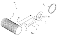
- FIG. 1 a schematic, exploded view of some of the main components of a harvesting device 20 of the present invention is illustrated in Fig. 1 .
- Fig. 1 illustrates a mounting member 1 formed as a hollow, cylindrical pipe provided with an outer periphery 22 to which a plurality of components can be attached.
- the mounting member 1 is configured to be mechanically connected to one or more driving units (not shown). Accordingly, the mounting member 1 is configured to transfer mechanical energy from one or more driving units to the components attached to the mounting member 1.
- the driving unit(s) may be of any suitable type, size and construction. In one embodiment according to the invention, the driving unit(s) may be a hydraulic motor mechanically connected to the mounting member 1 or to an element (e.g. an end plate 4) mechanically connected to the mounting member 1.
- the mounting member 1 may be provided as a shaft, provided with engagement structures such as teeth or grooves configured to be brought into engagement with corresponding engagement structures such as a chain, a gear or a timing belt.
- the harvesting device 20 comprises a blade 2 adapted to cut and/or lift structures during operation of the harvesting device 20.
- the blade 2 is attached to the mounting member 1 (see Fig. 4 , Fig. 5 , Fig. 6 and Fig. 7 ).
- the blade 2 can be detachably attached to the mounting member 1 by providing the outer periphery of the mounting member 1 and the inner periphery 21 of the blade 2 with corresponding engaging structures (e.g. corresponding grooves and protrusions).
- the blade 2 can be attached to the mounting member 1 by means of welding, or mechanical attachment means such as bolts, rivets, pop rivets, locking pins/locking devices and hinges. Accordingly, when the blade 2 is attached to the mounting member 1, the blade 2 will rotate together, and with the same rotational speed as the mounting member 1.
- the wear part 3 can be attached to the blade 2 by any suitable means including welding and mechanical attachment based on bolts, rivets or pop rivets. It can be seen that the geometry of the inner periphery 21 of the blade 2 corresponds to the geometry of the outer periphery 22 of the mounting member 1. It can also be seen that the length L 1 of the blade 2 exceeds the width W 2 of the blade 2. It should be noted that the length L 1 of the blade 2 will be slightly larger when the wear part 3 is attached to the blade 2.
- An annular end plate 4 provided with a centrally arranged aperture and a plurality of evenly distributed bores 23 is arranged next to the blade 2.
- the end plate 4 is adapted to be attached to the end portion of the mounting member 1.
- the end plate 4 can be attached to the end portion of the mounting member 1 by means of any suitable attachment techniques including welding and mechanical attachment structures such as bolts, rivets, pop rivets, locking pins/locking devices and hinges.
- the end plate 4 can be mechanically connected to a driving unit (not shown) by means of the bores 23 (e.g. by attaching a driving unit to the bores by using e.g. bolts).
- a wear ring 5 is provided next to the end plate 4.
- the wear ring 5 is adapted to be attached to the mounting member 1 and take up wear due to the motion of the mounting member 1 relative to a fixed structure (shown in Fig. 2B ) provided next to the blade 2.
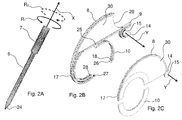
- Fig. 2A illustrates a schematic view of a grub tooth 6 according to one embodiment of the invention.
- the grub tooth 6 is formed as an elongated rod provided with a pointed distal end 24.
- the grub tooth 6 is joined in an elongated bearing 7.
- the bearing 7 is configured to be attached to the frame (see Fig. 3 , Fig. 5 and Fig. 6 ) of the harvesting device.
- the grub tooth 6 can rotate about its longitudinal axis X in either a first rotational direction R 1 or the opposite rotational direction R 2 as indicated.
- Fig. 2B illustrates a schematic, perspective view of a first displacement member (here exemplified by a curved rail 8) according to the invention.
- the rail 8 comprises a fixed portion having an arched structure provided with a circular arched distal portion, in which an attachment element 27 is provided.
- the rail 8 comprises a rotatably mounted fastening member shaped as a circular arched structure rotatably attached to the fixed portion 17 of the rail 8 by means of a hinged attachment structure 25.
- the hinged attachment structure 25 is provided with an attachment member 26 adapted to be mechanically attached to the attachment element 27 of the fixed portion 17 of the rail 8 by means of a locking pin 28 that is configured to be inserted into a bore 18 provided in the plate-shaped attachment member 26.
- the rail 8 comprises a rod member 9 and a reinforcement structure 30 provided as a plate extending between the rod member 9 and the outer periphery of the rail 8.
- the reinforcement structure 30 increases the mechanical strength and stiffness of the rail 8.
- the reinforcement structure 30 could have any suitable shape to withstand the pressure between the rail 8 and the rod member 9.
- An arched portion 29 is provided in the distal end of the reinforcement structure 30.
- the rail 8 comprises a U-shaped attachment structure 14 attached to the rod member 9.
- the attachment structure 14 is detachably attached to a support member 15 shaped as a shaft having a longitudinal axis Y.
- the rail 8 is configured to be detachably attached to a mounting member 1 as the one shown in Fig. 1 .
- the rail 8 is axially slidably. Accordingly, the rail 8 can move due to contact forces. Accordingly, the rail 8 will rather be displaced than be deformed when exposed to large forces and impacts.
- Fig. 2C illustrates a schematic, perspective view of a second curved rail 8 (example of displacement member) according to the invention.
- the rail 8 comprises a first fixed 17 portion having an arched structure.
- the rail 8 further comprises a second portion 10 (a fastening member) adapted to be attached to the fixed portion 17 e.g. by means of welding or mechanical attachment structures.
- the rail 8 comprises a plate-shaped reinforcement structure 30 and an annular attachment structure 14 adapted to be slidably attached to a support member 15 shaped as a shaft having a longitudinal axis Y.
- the rail 8 is configured to be detachably attached to a mounting member 1 as the one shown in Fig. 1 .
- the rail 8 is capable of being moved axially along the mounting member. Therefore, the rail 8 can move axially when exposed to large forces and impacts.
- Fig. 3 illustrates a schematic side view of a harvesting device 20 according to the invention.
- the harvesting device 20 comprises a frame 19 and a support member 15 attached thereto.
- the harvesting device 20 comprises a grub tooth 6 having a distal end formed as a pointed end 24.
- the grub tooth 6 is joined in an elongated bearing 7 attached to the frame 19 (e.g. by welding or by means of mechanical attachment elements such as bolts, rivets, pop rivets, locking pins/locking devices and hinges).
- the harvesting device 20 is provided with an end plate 4 attached to a cylindrical mounting member (not shown).
- the end plate 4 is provided with bores 23 for attachment of a driving unit (not shown).
- the harvesting device 20 comprises a plurality of blades 2, 2', 2" arranged in rows of three and fixed to the mounting member.
- the width W 2 of the blades 2, 2', 2" as well as the distance D between adjacent blades 2, 2', 2" (arranged in adjacent rows) are indicated in Fig. 3 .
- the blades 2, 2', 2" of one row are angular displaced relative to the adjacent row.
- the distance between D adjacent blades 2, 2', 2" of adjacent rows are smaller than the width W 2 of the blade 2, 2', 2".
- harvesting device 20 comprises a displacement member 8 formed as a curved rail 8.
- the rail is rotatably attached to the mounting member. Therefore, the rail 8 remains in a fixed position relative to frame when the mounting member rotates.
- the rail 8 comprises a rod member 9 and a C-shaped attachment structure 14 attached to an elongated support member 15 formed as a shaft extending parallel to the longitudinal axis of the mounting member.
- the length L 2 of the rail 8 is indicated.
- a rail 8 is arranged between all adjacent rows.
- the direction of travel 16 of the harvesting device 20 as well as the rotational direction ⁇ of the mounting member, the end plate 4 attached thereto and the blades 2 fixed to the mounting member are indicated in Fig. 3 .
- the rail 8 is provided with an arced distal portion 29.
- the arched portion 29 allows for arrangement of a transportation device.
- the distance D between adjacent blades 2, 2', 2" (arranged in adjacent rows) needs to be smaller than the size (the largest dimension) of the elements to be picked up by using the harvesting device 20.
- the number of rows depends on the working width of the harvesting device 20.
- Fig. 4 illustrates a schematic, perspective top view of a harvesting device 20 according to the invention.
- the harvesting device 20 comprises a cylindrical mounting member 1.
- a plurality of axially displaced rows 13, 13', 13', 13'" of blades 2, 2', 2" are fixed to the mounting member 1. Accordingly, the blades 2, 2', 2" will rotate with the same rotational speed as the mounting member 1.
- the displacement members (rails) arranged between the rows as well as a plurality of the rows have been removed from the mounting member 1 for illustrative purposes.
- Ring-shaped wear members 5, 5', 5" (wear rings) are arranged between adjacent rows 13, 13, 13", 13"'.
- the wear rings 5, 5', 5" are arranged and configured to take up wear originating from the rotating displacement members (rails) (not shown). Therefore, the wear rings 5, 5', 5" will be worn instead of the mounting member 1.
- the rotating displacement members (rails) can be axially displaced along the longitudinal axis Z of the mounting member 1.
- An end plate 4 is attached to the mounting member 1.
- the end plate 4 is provided with a centrally arranged circular bore and a plurality of smaller bores (preferably threaded bores) 23 for attaching a driving unit (not shown) to the end plate 4.
- the blades 2, 2' are provided with a wear part 3 attached thereto (e.g. by welding or by means of mechanical attachment structures such as bolts, rivets, pop rivet, locking pins/locking devices and hinges).
- a wear part 3 attached thereto (e.g. by welding or by means of mechanical attachment structures such as bolts, rivets, pop rivet, locking pins/locking devices and hinges).
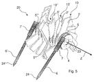
- Fig. 5 illustrates a schematic, perspective top view of a harvesting device 20 according to one embodiment of the invention.
- the harvesting device 20 comprises a cylindrical mounting member to which a plurality of axially displaced rows 13, 13', 13" are fixed.
- a wear ring 5, 5', 5", 5"' is arranged between all adjacent rows 13, 13', 13" to reduce wear of the mounting member caused by rotation and axial displacement (along the longitudinal axis Z of the mounting member) of displacement members (not shown) arranged between the adjacent rows 13, 13', 13".
- Fig. 5 The embodiment shown in Fig. 5 is provided with a first grub tooth 6 arranged at one side of the harvesting device 20 and a second grub tooth 6' arranged at the opposite side of the harvesting device 20.
- Each grub tooth 6, 6' is joined in an elongated bearing 7, 7'.
- the bearings 7, 7' are attached to the frame (not shown) of the harvesting device 20.
- Each grub tooth 6, 6' comprises a pointed end 24, 24' configured to be ground engaging. Accordingly, each grub tooth 6, 6' can loosen roots and other elements in the ground/soil and hereby grub the ground/soil.
- the width W 2 of the blades 2, 2', 2" prevents elements (e.g. roots) caught by the blades 2, 2', 2" of the harvesting device 20 to pass through the rear portion of a blade 2, 2', 2" and the front portion of the adjacent blade 2, 2', 2".
- Fig. 6 illustrates a perspective top view of a harvesting device 20 according to an embodiment of the invention.
- the harvesting device 20 comprises a cylindrical mounting member to which a plurality of axially displaced rows 13, 13', 13" are attached (e.g. by means of welding or mechanical attachment elements such as bolts, rivets, pop rivets, locking pins/locking devices and hinges).
- Each row 13, 13', 13" of the harvesting device 20 comprises three blades 2, 2', 2", however, the number of blades 2, 2', 2" in each row 13, 13', 13" may be lower (e.g. one or two blades 2, 2', 2" in each row 13, 13', 13") or be larger (e.g. four, five, six, seven, eight, nine, ten or more blades 2, 2', 2" in each row 13, 13', 13"). It can be seen that a displacement member (rail) 8, 8' is arranged between each set of adjacent rows 13, 13', 13".
- the displacement members (rails) 8, 8', 8" can radially displace elements (e.g. roots) that get stuck between adjacent rows 13, 13', 13" due to rotation of the mounting member 1.
- the geometry of the displacement members (rails) 8, 8', 8" ensures that elements (e.g. roots) that get stuck between adjacent rows 13, 13', 13" are gradually displaced radially as the mounting member is rotated and thus angular displaced relative to the displacement members (rails) 8, 8', 8".
- the outer periphery of the displacement members (rails) 8, 8', 8" have an increasing radius as function of the angular position. Accordingly, elements (e.g. roots) that get stuck between adjacent rows 13, 13', 13" due to rotation of the mounting member 1 will be radially displaced by the displacement members (rails) 8, 8', 8" until the elements (e.g. roots) are loosened from the adjacent rows 13, 13', 13".
- the harvesting device 20 comprises a frame 19 provided with two parallel elongated bars extending perpendicular to the longitudinal axis Z of the mounting member.
- the harvesting device 20 comprises a support member 15 shaped as an elongated rod (shaft) having a longitudinal axis Y extending parallel to the longitudinal axis Z of the mounting member.
- Each displacement member (rail) 8, 8' is slidably attached to the support member 15 by means of an attachment structure 14.
- the attachment structure 14 is attached to a rod member 9 of the displacement member (rail) 8, 8' 8".
- the harvesting device 20 comprises a first grub tooth 6 arranged at one side of the harvesting device 20 and a second grub tooth 6' arranged at the opposite side of the harvesting device 20.
- Each grub tooth 6, 6' is joined in an elongated bearing 7, 7'.
- the bearings 7, 7' are fixed to the frame 19 of the harvesting device 20 e.g. by welding or by mechanical fastening means such as bolts, rivets or pop rivets.
- Each grub tooth 6, 6' is provided with a pointed end 24, 24' adapted to be ground engaging. Accordingly, each grub tooth 6, 6' can loosen roots and other elements in the ground/soil and hereby grub the ground/soil.
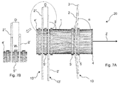
- Fig. 7A illustrates a schematic front view of a harvesting device 20 according to one embodiment of the invention.
- the harvesting device 20 comprises a cylindrical mounting member 1 provided with a first end plate 4 attached to the right end of the mounting member 1 and a second end plate 4' attached to the left end of the mounting member 1.
- the mounting member 1 has a longitudinal axis Z.
- a plurality of rows 13, 13', 13" of blades 2, 2', 2" are attached to the mounting member 1.
- the attachment of the blades 2, 2', 2" to the mounting member 1 may be carried out by means of any suitable fastenings means including welding and mechanical attachment structures such as bolts, rivets, pop rivets, locking pins/locking devices and hinges.
- the distance D between adjacent rows 13', 13" is indicated in Fig. 7 .
- the angle ⁇ between the blade 2 and the longitudinal axis Z of the mounting member 1 is approximately 85 degrees, whereas the angle ⁇ between the blade 2' and the longitudinal axis Z of the mounting member 1 is approximately 90 degrees.
- the angles ⁇ , ⁇ between the blades 2, 2', 2" and the longitudinal axis Z of the mounting member 1 may be varied within the range 80-100 degrees.
- the blades 2, 2', 2" are provided with a wear part 3. It can be seen that a wear ring 5, 5', 5" is arranged between adjacent rows 13, 13', 13".
- Fig. 7B illustrates a close-up view of a portion of the harvesting device 20 shown in Fig. 7A . It can be seen that the wear ring 5" is arranged to be axially displaced along the longitudinal axis Z of the mounting member 1 since the width W 1 of the wear ring 5" is smaller than the distance D between the adjacent rows 13', 13".
- FIG. 8A illustrates schematic, perspective view of a harvesting device 20 according to the invention having one blade 2, 2', 2" in each row.
- Fig. 8B illustrates another schematic, perspective view of the harvesting device 20 shown in Fig. 8A .
- Fig. 8C illustrates a schematic, perspective view of a harvesting device 20 according to the invention having two blades 2, 2', 2" in each row and Fig. 8D illustrates another schematic, perspective view of the harvesting device 20 shown in Fig. 8C . It can be seen that the blades 2, 2', 2" are evenly distributed along the periphery of the cylindrical mounting member whereto the blades 2, 2', 2" are attached.
- Fig. 8E illustrates a schematic, perspective view of a harvesting device 20 according to the invention having three blades 2, 2', 2" in each row and Fig. 8F illustrates another schematic, perspective view of the harvesting device 20 shown in Fig. 8E .
- the blades 2, 2', 2" are evenly distributed along the periphery of the cylindrical mounting member whereto the blades 2, 2', 2" are attached.
- Fig. 8G illustrates a schematic, perspective view of a harvesting device 20 according to the invention having four blades 2, 2', 2" in each row
- Fig. 8H illustrates another schematic, perspective view of the harvesting device 20 shown in Fig. 8F .
- the blades 2, 2', 2" are evenly distributed along the periphery of the cylindrical mounting member whereto the blades 2, 2', 2" are attached.
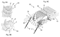
- Fig. 9A illustrates a schematic, perspective view of a harvesting device 20 according to the invention having five blades 2, 2', 2" in each row and Fig. 9B illustrates another schematic, perspective view of the harvesting device shown in Fig. 9A .
- the blades 2, 2', 2" are evenly distributed along the periphery of the cylindrical mounting member whereto the blades 2, 2', 2" are attached.
- Fig. 9C illustrates a schematic, perspective view of a harvesting device 20 according to the invention and a transporting device 32 attached thereto.
- the transporting device 32 is arranged close to the arched portion 29 of the displacement members (rails) 8 of the harvesting device 20.
- the harvesting device 20 comprises a frame 19 to and two grub teeth 6, 6' each being joined in an elongated bearing 7, 7' attached to the frame 19 of the harvesting device 20.
- the grub teeth 6, 6' are provided with protection shields 34, 34' arranged under the bearing 7, 7' to protect the bearing 7, 7' against soil and fragments from the ground.
Landscapes
- Life Sciences & Earth Sciences (AREA)
- Engineering & Computer Science (AREA)
- Mechanical Engineering (AREA)
- Soil Sciences (AREA)
- Environmental Sciences (AREA)
- Harvester Elements (AREA)
Description
- The present invention relates to a harvesting device. The harvesting device is particular suited for agricultural purposes, forestry, horticultural purposes and plant nurseries, e.g. in the collection and removal of structures, items and matter located on and/or in the ground.
- In particular, the invention relates to a harvesting device having a plurality of blades arranged in a plurality of axially displaced rows attached to a rotatably mounted mounting member, wherein the rows are configured to cut and/or pick up elements in or on the ground as well as in and on the ground, and wherein the mounting member is provided with one or more displacement members configured to radially displace elements that are arranged between adjacent rows due to rotation of the mounting member. The harvesting device is thereby is not only suited for collecting structures, items and matter located on and in the ground, but also suited for moving the so collected items and matter away from the harvesting device for further transportation.
- Sorters and rollers are often used for agricultural purposes. After harvesting, remains left in the soil must be removed to prepare the soil for new planting. This is e.g. the case in connection with culture of crops and smaller trees like Christmas trees. Furthermore, in general it may be necessary to remove and collect stones, roots and other debris from the soil before first-time planting in order to improve the quality of the soil, and, thus, improve the growth of the crop planted.
- From
EP 2 332 663 A1 - When using the prior art harvesting devices capable of picking up elements such as roots from the soil/ground, the elements picked up may be stuck and damage the harvesting device.
- Accordingly, there is a need for an improved harvesting device not possessing these drawbacks.
- The object of the present invention can be achieved by a harvesting device as defined in claim 1. Preferred embodiments are defined in the dependent sub claims, explained in the following description and illustrated in the accompanying drawings.
- The harvesting device according to the invention is a harvesting device having a plurality of blades arranged in a plurality of axially displaced rows attached to a rotatably mounted mounting member, wherein the rows are configured to cut and/or pick up elements in the ground, and wherein the mounting member is provided with one or more displacement members configured to radially displace elements that are arranged between adjacent rows due to rotation of the mounting member.
- Hereby, it is possible to remove elements that are stuck between adjacent rows by radially displacing the elements by means of the one or more displacement members.
- The axially displaced rows may comprise any suitable number of blades (e.g. one, two, three, four, five, six, seven, eight, nine, ten or more blades). The blades may preferably be evenly distributed along the periphery of the mounting member. The rows are configured to cut and/or pick up elements in the ground/soil. The number of rows may depend intended use and of the size of the blades in each row as well as the items to be collected/picked up. In general, the larger the distance between each row, the larger items to be collected/picked up. In general, the smaller the distance between each row, the smaller items to be collected/picked up.
- The mounting member is provided with one or more displacement members of any suitable size and geometry enabling the one or more displacement members to radially displace elements that are arranged between adjacent rows due to rotation of the mounting member. The one or more displacement members may include a rail, such as a curved or arched rail.
- It may be an advantage that each displacement member is provided with an attachment structure configured to be attached to a support member.
- Hereby, it is possible to support the displacement members to the support member and allow axial displacement of the displacement members. Accordingly, it is possible to provide a strong and reliable harvesting device.
- It may be beneficial that the displacement member is provided with a fastening member. Hereby, the mounting of the displacement member to the mounting member can be eased.
- It may be advantageous that a wear member detachably attached to the mounting member is provided between adjacent rows. Hereby, wear of the mounting member can be reduced or even prevented. Instead the wear members are worn and these wear members can easily be replaced with new ones.
- It may be beneficial that each wear member is configured to function as bearing for the displacement member and the fastening member. Hereby, the displacement members are capable of being kept in a fixed rotational position relative to the rotating mounting member.
- It may be an advantage that the width of the blade is larger than the distance between the distal edges of adjacent blades. Hereby, the picked-up elements cannot move axially to the adjacent row. In some embodiments, the blades and rows are mounted so as to form a repeated pattern as regards the distance between the distal edges of adjacent blades. The repeated pattern may depend on the number of blades on each row.
- It may be an advantage that the blade is provided with a wear part. Hereby, the wear part can be replaced instead of replacing the entire blade due to wear. The wear part may be attached to the blade by welding or by use of bolts, rivets or pop rivets, screws and/or locking pins/locking devices.
- It may be beneficial that the angle between the blade and the longitudinal axis of the mounting member is 80-100°. Hereby, the optimum conditions may be established in order to pick-up elements from the ground/soil. It is contemplated that the angle may suitably be 81°, 82°, 83°, 84°, 85°, 86°, 87°, 88°, 89°, 90°, 91°, 92°, 93°, 94°, 95°, 96°, 97°, 98°, 99° or 100°. Although the angle is exemplified with integers, it is to be understood that the angle may be any non-integer. In some embodiments, the blades of the various rows may be mounted with different angles. By way of example, some rows may have blades with an angle of 85°, while other rows have blades with an angle of 90°. By way of example, the row at the centre ("centre row") may have blades with an angle of 90°, whereas the rows on each side of the centre row have blades with different angles (e.g. 85° on the one side of the centre row, and e.g. 105° on the other side of the centre row).
- It may be an advantage that the harvesting device comprises a grub tooth, or two grub teeth. Hereby, the grub tooth or the two grub teeth can grub the ground/soil and hereby loosen elements to be picked-up by the harvesting device. The grub tooth may have any suitable form. In certain embodiments, the grub tooth is rod-shaped or lance-shaped.
- It may be beneficial that each grub tooth is rotatably mounted and configured to rotate about its longitudinal axis. Hereby, elements are prevented from being tangled up.
- It may be advantageous that the grub tooth is mounted on each side of the harvesting device. Hereby, it is possible to provide the most efficient harvesting device.
- It may be beneficial that each grub teeth is mounted in a bearing attached to a frame of the harvesting device. Hereby, it is possible to provide a reliable attachment of the grub teeth to the frame.
- It may be beneficial that the displacement member(s) are arranged between adjacent rows. Hereby, the displacement member(s) are capable of displacing elements being stuck between adjacent rows.
- It may be beneficial that the displacement member comprises two separated structures or a first structure and a second structure rotatably attached to the first structure. Hereby, the displacement member can be attached to the mounting member in an easy and user-friendly manner.
- It may be an advantage that the wear member is arranged between the displacement member and the mounting member. Hereby, the wear member is capable of reducing or even eliminating the wear of the mounting member.
- Each blade in each row is mounted on the mounting member by welding or by use of e.g. bolts, screws, rivets, pop rivets and/or locking pins/locking devices. The blades may be detachably mounted on the mounting member. Thus, the blades may easily be replaced.
- For some applications, a wear member may be provided between each row of blades. The wear member may be made of any suitable material, such as metal (e.g. steel and alloys) rubber or a silicone material.
- For some applications, the support member may be a shaft or a rod-shaped structure.
- For some applications, the mounting member may be a hollow, cylindrical pipe suitable for mounting thereon the various components (like, e.g., rows, blades, displacement members, wear parts and end plates), e.g. using bolts, rivets, pop rivets, screws, locking pins/locking devices, and/or hinges, or by welding. The mounting member may even be made up of a plurality of hollow, cylindrical, ring-shaped structures which can be assembled with the various components (like e.g. rows, blades, displacement members, wear parts and end plates), e.g. by bolts, rivets, screws, locking pins/locking devices, and/or hinges, or by welding. The mounting member may have a diameter suited for mounting or assembling the various attachments. The mounting member may be made of a metal or an alloy.
- For some applications, the number of displacement members equals the number of rows. For some applications, a displacement member is present at each side of each row, i.e. the number of displacement members equals the number of rows with the addition of two further displacement members.
- Between the displacement member and the fastening member, and the mounting member, a wear member may suitably be provided. Thus, the wear member may form a bearing for the displacement member and the fastening member, which wear member further reduces or even eliminates wearing, when the rows and mounting member are rotated.
- In some embodiments, the width of the displacement member increases at least until the length of the displacement member exceeds the length of the blades (i.e. is "free" of the blades). However, it is to be understood that the exact form and the width of the displace member depends on the intended use of the harvesting device and the items to be collected.
- The displacement member may suitably be provided with a cavity at the end opposite the mounting member. This cavity may suitably be such which fits a sorting or transportation structure, such as a conveyor belt or rollers.
- The displacement member may suitably be made of a metal (e.g. iron, steel or other alloys) or a composite or fibre material.
- The displacement member as such is also encompassed by the invention. The displacement member has the form and function as described herein. The displacement member may be used with any harvesting device ("retrofit"). By the term "retrofit" is meant that the displacement member is mounted on a harvesting device subsequently.
- When the harvesting device is moved across the ground, the blades are rotated. Thereby, the harvesting device loosens the soil and items/elements located in or on the ground is moved and can be collected. The collected items are moved across the displacement members away from the ground. The collected items may further be cleaned and/or sorted using conveyor belts or other techniques generally known in the art.
- In particular, the harvesting device is rotated in an opposite direction relative to direction of movement. Thereby, processing of the soil is achieved.'
- For transferring power for rotating the mounting member, the harvesting device may be provided with one, two or more end plates. The end plates may be provided with bores for bolts and/or screws fitting a drive shaft. The end plates may further be provided with a support bearing.
- Movement of the harvesting device may be accomplished by methods and techniques generally known in the art. The harvesting device may be powered by means of mechanical, electrical or hydraulic nature. In particular, the harvesting device may be connected to and towed by a vehicle (e.g. a tractor), or the harvesting device may be part of a self-propelling unit.
- It is to be understood that when the harvesting device is configured to be moving, the displacement members (e.g. curved or arched rails) are fixed to the frame of the harvesting device. Accordingly, the displacement members rotate relative to the rows of blades.
- In a particular embodiment of the harvesting device, one or more grub teeth are mounted. Specifically, a grub tooth may be mounted on each side of the harvesting device. The grub tooth may also be present at the one side only. It is contemplated that each grub tooth may rotate about its longitudinal axis. The rotation may be inwards or outwards relative to the mounting member. If two grub teeth are present, one may rotate inwards and one rotate outwards, or they may both rotate either inwards or outwards. The rotation may be provided by mechanical power, or the rotation may be freely. The grub tooth loosens the soil and items present in the soil, e.g. roots, weed, crops, debris and stones.
- In another aspect, the present invention relates to the use of the harvesting device for agricultural purposes and/or for soil treatment. The use is suitably such by which stones, weed, grass and/or roots located on or in the ground as well as on and in the ground are collected and optionally removed from the ground.
- In yet another aspect, the present invention relates to the harvesting device for use in soil treatment, whereby the harvesting device is used for collecting and optionally removing stones, weed, grass and/or roots located on or in the ground and in or on as well as in and on sandy areas such as a beach.
- The invention will become more fully understood from the detailed description given herein. The accompanying drawings are given by way of illustration only, and thus, they are not in any way limitative of the present invention. In the accompanying drawings:
- Fig. 1
- shows a schematic, exploded view of some of the main components of the harvesting device according to the invention;
- Fig. 2A
- shows a schematic, perspective view of a grub tooth according to one embodiment of the invention;
- Fig. 2C
- shows a schematic, perspective view of a displacement member according to another embodiment of the invention;
- Fig. 3
- shows a schematic, side view of an embodiment of the harvesting device of the invention;
- Fig. 4
- shows a schematic, perspective view of a harvesting device having according to one embodiment of the invention;
- Fig. 5
- shows a schematic, perspective side-view of a harvesting device according to the invention;
- Fig. 6
- shows a schematic, perspective side-view of another harvesting device according to the invention;
- Fig. 7A
- shows a schematic front view of a mounting member and a plurality of rows attached thereto;
- Fig. 7B
- shows a schematic close-up view of a part of the mounting member shown in
Fig. 7A ; - Fig. 8A
- shows a schematic, perspective view of a harvesting device according to the invention having one blade in each row;
- Fig. 8B
- shows another schematic, perspective view of the harvesting device shown in
Fig. 8A ; - Fig. 8C
- shows a schematic, perspective view of a harvesting device according to the invention having two blades in each row;
- Fig. 8D
- shows another schematic, perspective view of the harvesting device shown in
Fig. 8C ; - Fig. 8E
- shows a schematic, perspective view of a harvesting device according to the invention having three blades in each row;
- Fig. 8F
- shows another schematic, perspective view of the harvesting device shown in
Fig. 8E ; - Fig. 8G
- shows a schematic, perspective view of a harvesting device according to the invention having four blades in each row;
- Fig. 8H
- shows another schematic, perspective view of the harvesting device shown in
Fig. 8F ; - Fig. 9A
- shows a schematic, perspective view of a harvesting device according to the invention having five blades in each row;
- Fig. 9B
- shows another schematic, perspective view of the harvesting device shown in
Fig. 9A ; - Fig. 9C
- shows a schematic, perspective view of a harvesting device according to the invention and a transporting device attached thereto.
- Referring now in detail to the drawings for the purpose of illustrating preferred embodiments of the present invention, a schematic, exploded view of some of the main components of a
harvesting device 20 of the present invention is illustrated inFig. 1 . -
Fig. 1 illustrates a mounting member 1 formed as a hollow, cylindrical pipe provided with anouter periphery 22 to which a plurality of components can be attached. The mounting member 1 is configured to be mechanically connected to one or more driving units (not shown). Accordingly, the mounting member 1 is configured to transfer mechanical energy from one or more driving units to the components attached to the mounting member 1. The driving unit(s) may be of any suitable type, size and construction. In one embodiment according to the invention, the driving unit(s) may be a hydraulic motor mechanically connected to the mounting member 1 or to an element (e.g. an end plate 4) mechanically connected to the mounting member 1. - In another embodiment of the invention, the mounting member 1 may be provided as a shaft, provided with engagement structures such as teeth or grooves configured to be brought into engagement with corresponding engagement structures such as a chain, a gear or a timing belt.
- The
harvesting device 20 comprises ablade 2 adapted to cut and/or lift structures during operation of theharvesting device 20. When theharvesting device 20 is assembled, theblade 2 is attached to the mounting member 1 (seeFig. 4 ,Fig. 5 ,Fig. 6 andFig. 7 ). Theblade 2 can be detachably attached to the mounting member 1 by providing the outer periphery of the mounting member 1 and theinner periphery 21 of theblade 2 with corresponding engaging structures (e.g. corresponding grooves and protrusions). Theblade 2 can be attached to the mounting member 1 by means of welding, or mechanical attachment means such as bolts, rivets, pop rivets, locking pins/locking devices and hinges. Accordingly, when theblade 2 is attached to the mounting member 1, theblade 2 will rotate together, and with the same rotational speed as the mounting member 1. - In order not to replace the
blade 2 due to wear, it is possible to mount awear part 3 to the part of theblade 2 that is subject to the most critical wear. Thewear part 3 can be attached to theblade 2 by any suitable means including welding and mechanical attachment based on bolts, rivets or pop rivets. It can be seen that the geometry of theinner periphery 21 of theblade 2 corresponds to the geometry of theouter periphery 22 of the mounting member 1. It can also be seen that the length L1 of theblade 2 exceeds the width W2 of theblade 2. It should be noted that the length L1 of theblade 2 will be slightly larger when thewear part 3 is attached to theblade 2. - An
annular end plate 4 provided with a centrally arranged aperture and a plurality of evenly distributed bores 23 is arranged next to theblade 2. Theend plate 4 is adapted to be attached to the end portion of the mounting member 1. Theend plate 4 can be attached to the end portion of the mounting member 1 by means of any suitable attachment techniques including welding and mechanical attachment structures such as bolts, rivets, pop rivets, locking pins/locking devices and hinges. Theend plate 4 can be mechanically connected to a driving unit (not shown) by means of the bores 23 (e.g. by attaching a driving unit to the bores by using e.g. bolts). - A
wear ring 5 is provided next to theend plate 4. Thewear ring 5 is adapted to be attached to the mounting member 1 and take up wear due to the motion of the mounting member 1 relative to a fixed structure (shown inFig. 2B ) provided next to theblade 2. -
Fig. 2A illustrates a schematic view of agrub tooth 6 according to one embodiment of the invention. Thegrub tooth 6 is formed as an elongated rod provided with a pointeddistal end 24. Thegrub tooth 6 is joined in anelongated bearing 7. Thebearing 7 is configured to be attached to the frame (seeFig. 3 ,Fig. 5 andFig. 6 ) of the harvesting device. When mounted to the frame, thegrub tooth 6 can rotate about its longitudinal axis X in either a first rotational direction R1 or the opposite rotational direction R2 as indicated. -
Fig. 2B illustrates a schematic, perspective view of a first displacement member (here exemplified by a curved rail 8) according to the invention. Therail 8 comprises a fixed portion having an arched structure provided with a circular arched distal portion, in which anattachment element 27 is provided. Therail 8 comprises a rotatably mounted fastening member shaped as a circular arched structure rotatably attached to the fixedportion 17 of therail 8 by means of a hingedattachment structure 25. The hingedattachment structure 25 is provided with anattachment member 26 adapted to be mechanically attached to theattachment element 27 of the fixedportion 17 of therail 8 by means of a lockingpin 28 that is configured to be inserted into abore 18 provided in the plate-shapedattachment member 26. - The
rail 8 comprises arod member 9 and areinforcement structure 30 provided as a plate extending between therod member 9 and the outer periphery of therail 8. Thereinforcement structure 30 increases the mechanical strength and stiffness of therail 8. Although exemplified as a plate-shaped structure, it is to be understood that thereinforcement structure 30 could have any suitable shape to withstand the pressure between therail 8 and therod member 9. Anarched portion 29 is provided in the distal end of thereinforcement structure 30. - The
rail 8 comprises aU-shaped attachment structure 14 attached to therod member 9. Theattachment structure 14 is detachably attached to asupport member 15 shaped as a shaft having a longitudinal axis Y. Therail 8 is configured to be detachably attached to a mounting member 1 as the one shown inFig. 1 . When therail 8 is attached to the harvesting device, therail 8 is axially slidably. Accordingly, therail 8 can move due to contact forces. Accordingly, therail 8 will rather be displaced than be deformed when exposed to large forces and impacts. -
Fig. 2C illustrates a schematic, perspective view of a second curved rail 8 (example of displacement member) according to the invention. Therail 8 comprises a first fixed 17 portion having an arched structure. Therail 8 further comprises a second portion 10 (a fastening member) adapted to be attached to the fixedportion 17 e.g. by means of welding or mechanical attachment structures. Therail 8 comprises a plate-shapedreinforcement structure 30 and anannular attachment structure 14 adapted to be slidably attached to asupport member 15 shaped as a shaft having a longitudinal axis Y. Therail 8 is configured to be detachably attached to a mounting member 1 as the one shown inFig. 1 . When therail 8 is mounted on the mounting member of the harvesting device, therail 8 is capable of being moved axially along the mounting member. Therefore, therail 8 can move axially when exposed to large forces and impacts. -
Fig. 3 illustrates a schematic side view of aharvesting device 20 according to the invention. Theharvesting device 20 comprises aframe 19 and asupport member 15 attached thereto. Theharvesting device 20 comprises agrub tooth 6 having a distal end formed as apointed end 24. Thegrub tooth 6 is joined in anelongated bearing 7 attached to the frame 19 (e.g. by welding or by means of mechanical attachment elements such as bolts, rivets, pop rivets, locking pins/locking devices and hinges). - The
harvesting device 20 is provided with anend plate 4 attached to a cylindrical mounting member (not shown). Theend plate 4 is provided withbores 23 for attachment of a driving unit (not shown). Theharvesting device 20 comprises a plurality ofblades blades adjacent blades Fig. 3 . Theblades adjacent blades blade - It can be seen that
harvesting device 20 comprises adisplacement member 8 formed as acurved rail 8. The rail is rotatably attached to the mounting member. Therefore, therail 8 remains in a fixed position relative to frame when the mounting member rotates. Therail 8 comprises arod member 9 and a C-shapedattachment structure 14 attached to anelongated support member 15 formed as a shaft extending parallel to the longitudinal axis of the mounting member. The length L2 of therail 8 is indicated. In one embodiment according to the invention arail 8 is arranged between all adjacent rows. - The direction of
travel 16 of theharvesting device 20 as well as the rotational direction ω of the mounting member, theend plate 4 attached thereto and theblades 2 fixed to the mounting member are indicated inFig. 3 . - The
rail 8 is provided with an arceddistal portion 29. Thearched portion 29 allows for arrangement of a transportation device. - The distance D between
adjacent blades harvesting device 20. - The number of rows depends on the working width of the
harvesting device 20. -
Fig. 4 illustrates a schematic, perspective top view of aharvesting device 20 according to the invention. Theharvesting device 20 comprises a cylindrical mounting member 1. A plurality of axially displacedrows 13, 13', 13', 13'" ofblades blades - Ring-shaped
wear members adjacent rows - An
end plate 4 is attached to the mounting member 1. Theend plate 4 is provided with a centrally arranged circular bore and a plurality of smaller bores (preferably threaded bores) 23 for attaching a driving unit (not shown) to theend plate 4. - The
blades 2, 2' are provided with awear part 3 attached thereto (e.g. by welding or by means of mechanical attachment structures such as bolts, rivets, pop rivet, locking pins/locking devices and hinges). Hereby, it is possible to replace only thewear part 3 instead of replacing theentire blade 2, 2' in case of wear. -
Fig. 5 illustrates a schematic, perspective top view of aharvesting device 20 according to one embodiment of the invention. Theharvesting device 20 comprises a cylindrical mounting member to which a plurality of axially displacedrows wear ring adjacent rows adjacent rows - The embodiment shown in
Fig. 5 is provided with afirst grub tooth 6 arranged at one side of theharvesting device 20 and a second grub tooth 6' arranged at the opposite side of theharvesting device 20. Eachgrub tooth 6, 6' is joined in anelongated bearing 7, 7'. Thebearings 7, 7' are attached to the frame (not shown) of theharvesting device 20. Eachgrub tooth 6, 6' comprises apointed end grub tooth 6, 6' can loosen roots and other elements in the ground/soil and hereby grub the ground/soil. - The width W2 of the
blades blades harvesting device 20 to pass through the rear portion of ablade adjacent blade -
Fig. 6 illustrates a perspective top view of aharvesting device 20 according to an embodiment of the invention. Theharvesting device 20 comprises a cylindrical mounting member to which a plurality of axially displacedrows - An
end plate 4 is attached to the mounting member for enabling fixation of a driving unit (not shown), e.g. by means of thebores 23 provided in theend plate 4. Eachrow harvesting device 20 comprises threeblades blades row blades row more blades row adjacent rows adjacent rows adjacent rows - The outer periphery of the displacement members (rails) 8, 8', 8" have an increasing radius as function of the angular position. Accordingly, elements (e.g. roots) that get stuck between
adjacent rows adjacent rows - The
harvesting device 20 comprises aframe 19 provided with two parallel elongated bars extending perpendicular to the longitudinal axis Z of the mounting member. Theharvesting device 20 comprises asupport member 15 shaped as an elongated rod (shaft) having a longitudinal axis Y extending parallel to the longitudinal axis Z of the mounting member. - Each displacement member (rail) 8, 8' is slidably attached to the
support member 15 by means of anattachment structure 14. Theattachment structure 14 is attached to arod member 9 of the displacement member (rail) 8, 8' 8". - The
harvesting device 20 comprises afirst grub tooth 6 arranged at one side of theharvesting device 20 and a second grub tooth 6' arranged at the opposite side of theharvesting device 20. Eachgrub tooth 6, 6' is joined in anelongated bearing 7, 7'. Thebearings 7, 7' are fixed to theframe 19 of theharvesting device 20 e.g. by welding or by mechanical fastening means such as bolts, rivets or pop rivets. Eachgrub tooth 6, 6' is provided with apointed end grub tooth 6, 6' can loosen roots and other elements in the ground/soil and hereby grub the ground/soil. -
Fig. 7A illustrates a schematic front view of aharvesting device 20 according to one embodiment of the invention. Theharvesting device 20 comprises a cylindrical mounting member 1 provided with afirst end plate 4 attached to the right end of the mounting member 1 and a second end plate 4' attached to the left end of the mounting member 1. The mounting member 1 has a longitudinal axis Z. - A plurality of
rows blades blades adjacent rows 13', 13" is indicated inFig. 7 . - It should be stressed that the displacement members (rails) arranged between the
rows - The angle α between the
blade 2 and the longitudinal axis Z of the mounting member 1 is approximately 85 degrees, whereas the angle β between the blade 2' and the longitudinal axis Z of the mounting member 1 is approximately 90 degrees. The angles α, β between theblades blades wear part 3. It can be seen that awear ring adjacent rows -
Fig. 7B illustrates a close-up view of a portion of theharvesting device 20 shown inFig. 7A . It can be seen that thewear ring 5" is arranged to be axially displaced along the longitudinal axis Z of the mounting member 1 since the width W1 of thewear ring 5" is smaller than the distance D between theadjacent rows 13', 13". -
Fig. 8A illustrates schematic, perspective view of aharvesting device 20 according to the invention having oneblade Fig. 8B illustrates another schematic, perspective view of theharvesting device 20 shown inFig. 8A . -
Fig. 8C illustrates a schematic, perspective view of aharvesting device 20 according to the invention having twoblades Fig. 8D illustrates another schematic, perspective view of theharvesting device 20 shown inFig. 8C . It can be seen that theblades blades -
Fig. 8E illustrates a schematic, perspective view of aharvesting device 20 according to the invention having threeblades Fig. 8F illustrates another schematic, perspective view of theharvesting device 20 shown inFig. 8E . Theblades blades -
Fig. 8G illustrates a schematic, perspective view of aharvesting device 20 according to the invention having fourblades Fig. 8H illustrates another schematic, perspective view of theharvesting device 20 shown inFig. 8F . Theblades blades -
Fig. 9A illustrates a schematic, perspective view of aharvesting device 20 according to the invention having fiveblades Fig. 9B illustrates another schematic, perspective view of the harvesting device shown inFig. 9A . Theblades blades -
Fig. 9C illustrates a schematic, perspective view of aharvesting device 20 according to the invention and a transportingdevice 32 attached thereto. The transportingdevice 32 is arranged close to thearched portion 29 of the displacement members (rails) 8 of theharvesting device 20. Theharvesting device 20 comprises aframe 19 to and twogrub teeth 6, 6' each being joined in anelongated bearing 7, 7' attached to theframe 19 of theharvesting device 20. Thegrub teeth 6, 6' are provided withprotection shields 34, 34' arranged under thebearing 7, 7' to protect thebearing 7, 7' against soil and fragments from the ground. -
- 1
- Mounting member
- 2, 2', 2"
- Blade
- 3
- Wearing part
- 4, 4'
- End plate
- 5, 5', 5", 5"'
- Wearing member
- 6, 6'
- Grub tooth
- 7, 7'
- Bearing
- 8, 8', 8"
- Displacement member (rail)
- 9
- Rod member
- 10
- Fastening member
- 12
- Distal edge
- 13, 13', 13", 13"'
- Row
- 14
- Attachment structure
- 15
- Support member
- 16
- Direction
- 17
- Fixed portion
- 18
- Bore
- 19
- Frame
- 20
- Harvesting device
- 21
- Inner periphery
- 22
- Outer periphery
- 23
- Bore
- 24, 24'
- Pointed end
- 25
- Hinged attachment structure
- 26
- Attachment member
- 27
- Attachment element
- 28
- Locking pin
- 29
- Arced portion
- 30
- Reinforcement structure
- 32
- Transporting device
- 34, 34'
- Protection shield
- ω
- Rotational direction
- α, β
- Angle
- R1, R2
- Rotational direction
- W1, W2
- Width
- L1, L2
- Length
- D
- Distance
- X, Y, Z
- Longitudinal axis
Claims (15)
- Harvesting device (20) having a plurality of blades (2, 2') arranged in a plurality of axially displaced rows (13, 13', 13") attached to a rotatably mounted mounting member (1), wherein the rows (13, 13', 13") are configured to cut and/or pick up elements in the ground, characterised in that the mounting member (1) is provided with one or more displacement members (8) configured to radially displace elements that are arranged between adjacent rows (13, 13', 13") due to rotation of the mounting member (1).
- Harvesting device (20) according to claim 1, characterised in that each displacement member (8) is provided with an attachment structure (14) configured to be attached to a support member (15).
- Harvesting device (20) according to claim 1 or 2, characterised in that the displacement member (8) is provided with a fastening member (10).
- Harvesting device (20) according to any one of claims 1-3, characterised in that a wear member (5) detachably attached to the mounting member (1) is provided between adjacent rows (13, 13', 13").
- Harvesting device (20) according to claim 4, characterised in that each wear member (5) is configured to function as bearing for the displacement member (8) and the fastening member (10).
- Harvesting device (20) according to any one of claims 1-5, characterised in that the width (W) of the blade (2) is larger than the distance (D) between the distal edges of adjacent blades (2, 2').
- Harvesting device (20) according to any one of claims 1-6, characterised in that the blade (2) is provided with a wear part (3).
- Harvesting device (20) according to any one of claims 1-7, characterised in that the angle (α) between the blade (2, 2', 2") and the longitudinal axis (Z) of the mounting member (1) is 80°-100°.
- Harvesting device (20) according to any one of claims 1-10, characterised in that it further comprises a grub tooth (6, 6') or two grub teeth (6, 6').
- Harvesting device (20) according to claim 9, characterised in that each grub tooth (6, 6') is rotatably mounted and configured to rotate about its longitudinal axis (X).
- Harvesting device (20) according to any one of claims 9-10, characterised in that the grub tooth (6, 6') is mounted on each side of the harvesting device (20).
- Harvesting device (20) according to any one of claims 11-14, characterised in that the each grub teeth (6, 6') is mounted in a bearing (7, 7') attached to a frame (19) of the harvesting device (20).
- Harvesting device (20) according to one of the preceding claims, characterised in that the displacement member(s) (8) are arranged between adjacent rows (13, 13', 13").
- Harvesting device (20) according to one of the preceding claims, characterised in that the displacement member (8) comprises two separated structures or a first structure and a second structure rotatably attached to the first structure.
- Harvesting device (20) according to one of the preceding claims 4-14, characterised in that the wear member (5) is arranged between the displacement member (8) and the mounting member (1).
Applications Claiming Priority (2)
| Application Number | Priority Date | Filing Date | Title |
|---|---|---|---|
| DK201400114U DK201400114U3 (en) | 2014-08-20 | 2014-08-20 | Vertical Sorts |
| DKPA201500439A DK178716B1 (en) | 2014-08-20 | 2015-08-03 | Vertical sorter |
Publications (3)
| Publication Number | Publication Date |
|---|---|
| EP3127419A1 true EP3127419A1 (en) | 2017-02-08 |
| EP3127419A8 EP3127419A8 (en) | 2017-07-19 |
| EP3127419B1 EP3127419B1 (en) | 2020-02-12 |
Family
ID=56609680
Family Applications (1)
| Application Number | Title | Priority Date | Filing Date |
|---|---|---|---|
| EP16182203.6A Active EP3127419B1 (en) | 2014-08-20 | 2016-08-01 | Harvesting device |
Country Status (1)
| Country | Link |
|---|---|
| EP (1) | EP3127419B1 (en) |
Citations (4)
| Publication number | Priority date | Publication date | Assignee | Title |
|---|---|---|---|---|
| DE1482831B1 (en) * | 1964-10-16 | 1971-04-22 | Lely Nv C Van Der | Recording devices for hay, green fodder or the like. |
| FR2281050A1 (en) * | 1974-08-09 | 1976-03-05 | Amazonen Werke Dreyer H | COMPACTION CYLINDER, ESPECIALLY FOR AGRICULTURAL WORK |
| US6526736B1 (en) * | 2001-12-26 | 2003-03-04 | Deere & Company | Rotary conveyor tine stripper with anti-wrap relief and/or notching |
| EP2332663A1 (en) | 2009-10-12 | 2011-06-15 | Backers Maschinenbau GmbH | Screen element, screen shaft and star or disc screen |
Family Cites Families (1)
| Publication number | Priority date | Publication date | Assignee | Title |
|---|---|---|---|---|
| NL8203045A (en) * | 1982-07-30 | 1984-02-16 | Lely Nv C Van Der | SOIL TILLER. |
-
2016
- 2016-08-01 EP EP16182203.6A patent/EP3127419B1/en active Active
Patent Citations (4)
| Publication number | Priority date | Publication date | Assignee | Title |
|---|---|---|---|---|
| DE1482831B1 (en) * | 1964-10-16 | 1971-04-22 | Lely Nv C Van Der | Recording devices for hay, green fodder or the like. |
| FR2281050A1 (en) * | 1974-08-09 | 1976-03-05 | Amazonen Werke Dreyer H | COMPACTION CYLINDER, ESPECIALLY FOR AGRICULTURAL WORK |
| US6526736B1 (en) * | 2001-12-26 | 2003-03-04 | Deere & Company | Rotary conveyor tine stripper with anti-wrap relief and/or notching |
| EP2332663A1 (en) | 2009-10-12 | 2011-06-15 | Backers Maschinenbau GmbH | Screen element, screen shaft and star or disc screen |
Also Published As
| Publication number | Publication date |
|---|---|
| EP3127419A8 (en) | 2017-07-19 |
| EP3127419B1 (en) | 2020-02-12 |
Similar Documents
| Publication | Publication Date | Title |
|---|---|---|
| US7930870B2 (en) | Stalk roll and stripper arrangement for corn head | |
| US7752829B1 (en) | Auger stripper arrangement for corn head | |
| CA2884908C (en) | Harvested crop pick-up | |
| JP5022269B2 (en) | Barrel | |
| CA2314837C (en) | Harvesting device for harvesting ears of corn and similar crops | |
| US20030110752A1 (en) | Guard for crop pick up apparatus | |
| US8312700B2 (en) | Tine assembly | |
| CN114916264A (en) | Reverse speed difference chain residual film recovery machine and residual film recovery method | |
| KR101282927B1 (en) | Forward type agricultural products for tractor | |
| EP2700296B1 (en) | Device for picking up and transporting mown agricultural crops lying on the ground surface | |
| US7051505B2 (en) | Tomato harvester | |
| US9775293B2 (en) | Harvest sweeper attachment system | |
| JP2018014901A (en) | Vegetable harvester | |
| EP0236106A2 (en) | Grass, cereal crop, forage or hay pick-up machine | |
| US5076046A (en) | Harvester for vine crops | |
| US8590283B2 (en) | Downed corn rake | |
| EP3127419B1 (en) | Harvesting device | |
| KR100652515B1 (en) | Cultivator Attached Sweet Potato Harvester | |
| US10737297B2 (en) | Stone sieve apparatus | |
| US8291562B2 (en) | Rake tine replacement tool | |
| CN207573920U (en) | A kind of potato picker | |
| WO2021026635A1 (en) | Knife brush for a header reel | |
| CN201789783U (en) | Straw picking and conveying device | |
| CN201509428U (en) | Potato harvester | |
| CN113079720B (en) | Mulching film recycling and conveying mechanism and recycling and conveying method for mulching film recycling machine |
Legal Events
| Date | Code | Title | Description |
|---|---|---|---|
| PUAI | Public reference made under article 153(3) epc to a published international application that has entered the european phase |
Free format text: ORIGINAL CODE: 0009012 |
|
| STAA | Information on the status of an ep patent application or granted ep patent |
Free format text: STATUS: THE APPLICATION HAS BEEN PUBLISHED |
|
| AK | Designated contracting states |
Kind code of ref document: A1 Designated state(s): AL AT BE BG CH CY CZ DE DK EE ES FI FR GB GR HR HU IE IS IT LI LT LU LV MC MK MT NL NO PL PT RO RS SE SI SK SM TR |
|
| AX | Request for extension of the european patent |
Extension state: BA ME |
|
| RAP1 | Party data changed (applicant data changed or rights of an application transferred) |
Owner name: LAURSEN, NIELS KJAER |
|
| RIN1 | Information on inventor provided before grant (corrected) |
Inventor name: LAURSEN, NIELS KJAER |
|
| STAA | Information on the status of an ep patent application or granted ep patent |
Free format text: STATUS: REQUEST FOR EXAMINATION WAS MADE |
|
| 17P | Request for examination filed |
Effective date: 20170802 |
|
| RBV | Designated contracting states (corrected) |
Designated state(s): AL AT BE BG CH CY CZ DE DK EE ES FI FR GB GR HR HU IE IS IT LI LT LU LV MC MK MT NL NO PL PT RO RS SE SI SK SM TR |
|
| STAA | Information on the status of an ep patent application or granted ep patent |
Free format text: STATUS: EXAMINATION IS IN PROGRESS |
|
| 17Q | First examination report despatched |
Effective date: 20180103 |
|
| GRAP | Despatch of communication of intention to grant a patent |
Free format text: ORIGINAL CODE: EPIDOSNIGR1 |
|
| STAA | Information on the status of an ep patent application or granted ep patent |
Free format text: STATUS: GRANT OF PATENT IS INTENDED |
|
| INTG | Intention to grant announced |
Effective date: 20190910 |
|
| GRAS | Grant fee paid |
Free format text: ORIGINAL CODE: EPIDOSNIGR3 |
|
| GRAA | (expected) grant |
Free format text: ORIGINAL CODE: 0009210 |
|
| STAA | Information on the status of an ep patent application or granted ep patent |
Free format text: STATUS: THE PATENT HAS BEEN GRANTED |
|
| AK | Designated contracting states |
Kind code of ref document: B1 Designated state(s): AL AT BE BG CH CY CZ DE DK EE ES FI FR GB GR HR HU IE IS IT LI LT LU LV MC MK MT NL NO PL PT RO RS SE SI SK SM TR |
|
| REG | Reference to a national code |
Ref country code: GB Ref legal event code: FG4D |
|
| REG | Reference to a national code |
Ref country code: CH Ref legal event code: EP |
|
| REG | Reference to a national code |
Ref country code: AT Ref legal event code: REF Ref document number: 1230868 Country of ref document: AT Kind code of ref document: T Effective date: 20200215 |
|
| REG | Reference to a national code |
Ref country code: IE Ref legal event code: FG4D |
|
| REG | Reference to a national code |
Ref country code: DE Ref legal event code: R096 Ref document number: 602016029398 Country of ref document: DE |
|
| PG25 | Lapsed in a contracting state [announced via postgrant information from national office to epo] |
Ref country code: FI Free format text: LAPSE BECAUSE OF FAILURE TO SUBMIT A TRANSLATION OF THE DESCRIPTION OR TO PAY THE FEE WITHIN THE PRESCRIBED TIME-LIMIT Effective date: 20200212 Ref country code: NO Free format text: LAPSE BECAUSE OF FAILURE TO SUBMIT A TRANSLATION OF THE DESCRIPTION OR TO PAY THE FEE WITHIN THE PRESCRIBED TIME-LIMIT Effective date: 20200512 Ref country code: RS Free format text: LAPSE BECAUSE OF FAILURE TO SUBMIT A TRANSLATION OF THE DESCRIPTION OR TO PAY THE FEE WITHIN THE PRESCRIBED TIME-LIMIT Effective date: 20200212 |
|
| REG | Reference to a national code |
Ref country code: LT Ref legal event code: MG4D |
|
| REG | Reference to a national code |
Ref country code: NL Ref legal event code: MP Effective date: 20200212 |
|
| PG25 | Lapsed in a contracting state [announced via postgrant information from national office to epo] |
Ref country code: SE Free format text: LAPSE BECAUSE OF FAILURE TO SUBMIT A TRANSLATION OF THE DESCRIPTION OR TO PAY THE FEE WITHIN THE PRESCRIBED TIME-LIMIT Effective date: 20200212 Ref country code: LV Free format text: LAPSE BECAUSE OF FAILURE TO SUBMIT A TRANSLATION OF THE DESCRIPTION OR TO PAY THE FEE WITHIN THE PRESCRIBED TIME-LIMIT Effective date: 20200212 Ref country code: HR Free format text: LAPSE BECAUSE OF FAILURE TO SUBMIT A TRANSLATION OF THE DESCRIPTION OR TO PAY THE FEE WITHIN THE PRESCRIBED TIME-LIMIT Effective date: 20200212 Ref country code: GR Free format text: LAPSE BECAUSE OF FAILURE TO SUBMIT A TRANSLATION OF THE DESCRIPTION OR TO PAY THE FEE WITHIN THE PRESCRIBED TIME-LIMIT Effective date: 20200513 Ref country code: IS Free format text: LAPSE BECAUSE OF FAILURE TO SUBMIT A TRANSLATION OF THE DESCRIPTION OR TO PAY THE FEE WITHIN THE PRESCRIBED TIME-LIMIT Effective date: 20200612 Ref country code: BG Free format text: LAPSE BECAUSE OF FAILURE TO SUBMIT A TRANSLATION OF THE DESCRIPTION OR TO PAY THE FEE WITHIN THE PRESCRIBED TIME-LIMIT Effective date: 20200512 |
|
| PG25 | Lapsed in a contracting state [announced via postgrant information from national office to epo] |
Ref country code: NL Free format text: LAPSE BECAUSE OF FAILURE TO SUBMIT A TRANSLATION OF THE DESCRIPTION OR TO PAY THE FEE WITHIN THE PRESCRIBED TIME-LIMIT Effective date: 20200212 |
|
| PG25 | Lapsed in a contracting state [announced via postgrant information from national office to epo] |
Ref country code: SM Free format text: LAPSE BECAUSE OF FAILURE TO SUBMIT A TRANSLATION OF THE DESCRIPTION OR TO PAY THE FEE WITHIN THE PRESCRIBED TIME-LIMIT Effective date: 20200212 Ref country code: EE Free format text: LAPSE BECAUSE OF FAILURE TO SUBMIT A TRANSLATION OF THE DESCRIPTION OR TO PAY THE FEE WITHIN THE PRESCRIBED TIME-LIMIT Effective date: 20200212 Ref country code: LT Free format text: LAPSE BECAUSE OF FAILURE TO SUBMIT A TRANSLATION OF THE DESCRIPTION OR TO PAY THE FEE WITHIN THE PRESCRIBED TIME-LIMIT Effective date: 20200212 Ref country code: DK Free format text: LAPSE BECAUSE OF FAILURE TO SUBMIT A TRANSLATION OF THE DESCRIPTION OR TO PAY THE FEE WITHIN THE PRESCRIBED TIME-LIMIT Effective date: 20200212 Ref country code: RO Free format text: LAPSE BECAUSE OF FAILURE TO SUBMIT A TRANSLATION OF THE DESCRIPTION OR TO PAY THE FEE WITHIN THE PRESCRIBED TIME-LIMIT Effective date: 20200212 Ref country code: PT Free format text: LAPSE BECAUSE OF FAILURE TO SUBMIT A TRANSLATION OF THE DESCRIPTION OR TO PAY THE FEE WITHIN THE PRESCRIBED TIME-LIMIT Effective date: 20200705 Ref country code: CZ Free format text: LAPSE BECAUSE OF FAILURE TO SUBMIT A TRANSLATION OF THE DESCRIPTION OR TO PAY THE FEE WITHIN THE PRESCRIBED TIME-LIMIT Effective date: 20200212 Ref country code: ES Free format text: LAPSE BECAUSE OF FAILURE TO SUBMIT A TRANSLATION OF THE DESCRIPTION OR TO PAY THE FEE WITHIN THE PRESCRIBED TIME-LIMIT Effective date: 20200212 Ref country code: SK Free format text: LAPSE BECAUSE OF FAILURE TO SUBMIT A TRANSLATION OF THE DESCRIPTION OR TO PAY THE FEE WITHIN THE PRESCRIBED TIME-LIMIT Effective date: 20200212 |
|
| REG | Reference to a national code |
Ref country code: DE Ref legal event code: R097 Ref document number: 602016029398 Country of ref document: DE |
|
| REG | Reference to a national code |
Ref country code: AT Ref legal event code: MK05 Ref document number: 1230868 Country of ref document: AT Kind code of ref document: T Effective date: 20200212 |
|
| PLBE | No opposition filed within time limit |
Free format text: ORIGINAL CODE: 0009261 |
|
| STAA | Information on the status of an ep patent application or granted ep patent |
Free format text: STATUS: NO OPPOSITION FILED WITHIN TIME LIMIT |
|
| 26N | No opposition filed |
Effective date: 20201113 |
|
| PG25 | Lapsed in a contracting state [announced via postgrant information from national office to epo] |
Ref country code: AT Free format text: LAPSE BECAUSE OF FAILURE TO SUBMIT A TRANSLATION OF THE DESCRIPTION OR TO PAY THE FEE WITHIN THE PRESCRIBED TIME-LIMIT Effective date: 20200212 Ref country code: IT Free format text: LAPSE BECAUSE OF FAILURE TO SUBMIT A TRANSLATION OF THE DESCRIPTION OR TO PAY THE FEE WITHIN THE PRESCRIBED TIME-LIMIT Effective date: 20200212 |
|
| PG25 | Lapsed in a contracting state [announced via postgrant information from national office to epo] |
Ref country code: PL Free format text: LAPSE BECAUSE OF FAILURE TO SUBMIT A TRANSLATION OF THE DESCRIPTION OR TO PAY THE FEE WITHIN THE PRESCRIBED TIME-LIMIT Effective date: 20200212 Ref country code: SI Free format text: LAPSE BECAUSE OF FAILURE TO SUBMIT A TRANSLATION OF THE DESCRIPTION OR TO PAY THE FEE WITHIN THE PRESCRIBED TIME-LIMIT Effective date: 20200212 |
|
| PG25 | Lapsed in a contracting state [announced via postgrant information from national office to epo] |
Ref country code: MC Free format text: LAPSE BECAUSE OF FAILURE TO SUBMIT A TRANSLATION OF THE DESCRIPTION OR TO PAY THE FEE WITHIN THE PRESCRIBED TIME-LIMIT Effective date: 20200212 |
|
| REG | Reference to a national code |
Ref country code: CH Ref legal event code: PL |
|
| GBPC | Gb: european patent ceased through non-payment of renewal fee |
Effective date: 20200801 |
|
| PG25 | Lapsed in a contracting state [announced via postgrant information from national office to epo] |
Ref country code: CH Free format text: LAPSE BECAUSE OF NON-PAYMENT OF DUE FEES Effective date: 20200831 Ref country code: LI Free format text: LAPSE BECAUSE OF NON-PAYMENT OF DUE FEES Effective date: 20200831 Ref country code: LU Free format text: LAPSE BECAUSE OF NON-PAYMENT OF DUE FEES Effective date: 20200801 |
|
| REG | Reference to a national code |
Ref country code: BE Ref legal event code: MM Effective date: 20200831 |
|
| PG25 | Lapsed in a contracting state [announced via postgrant information from national office to epo] |
Ref country code: FR Free format text: LAPSE BECAUSE OF NON-PAYMENT OF DUE FEES Effective date: 20200831 |
|
| PG25 | Lapsed in a contracting state [announced via postgrant information from national office to epo] |
Ref country code: IE Free format text: LAPSE BECAUSE OF NON-PAYMENT OF DUE FEES Effective date: 20200801 Ref country code: GB Free format text: LAPSE BECAUSE OF NON-PAYMENT OF DUE FEES Effective date: 20200801 Ref country code: BE Free format text: LAPSE BECAUSE OF NON-PAYMENT OF DUE FEES Effective date: 20200831 |
|
| PG25 | Lapsed in a contracting state [announced via postgrant information from national office to epo] |
Ref country code: TR Free format text: LAPSE BECAUSE OF FAILURE TO SUBMIT A TRANSLATION OF THE DESCRIPTION OR TO PAY THE FEE WITHIN THE PRESCRIBED TIME-LIMIT Effective date: 20200212 Ref country code: MT Free format text: LAPSE BECAUSE OF FAILURE TO SUBMIT A TRANSLATION OF THE DESCRIPTION OR TO PAY THE FEE WITHIN THE PRESCRIBED TIME-LIMIT Effective date: 20200212 Ref country code: CY Free format text: LAPSE BECAUSE OF FAILURE TO SUBMIT A TRANSLATION OF THE DESCRIPTION OR TO PAY THE FEE WITHIN THE PRESCRIBED TIME-LIMIT Effective date: 20200212 |
|
| PG25 | Lapsed in a contracting state [announced via postgrant information from national office to epo] |
Ref country code: MK Free format text: LAPSE BECAUSE OF FAILURE TO SUBMIT A TRANSLATION OF THE DESCRIPTION OR TO PAY THE FEE WITHIN THE PRESCRIBED TIME-LIMIT Effective date: 20200212 Ref country code: AL Free format text: LAPSE BECAUSE OF FAILURE TO SUBMIT A TRANSLATION OF THE DESCRIPTION OR TO PAY THE FEE WITHIN THE PRESCRIBED TIME-LIMIT Effective date: 20200212 |
|
| PGFP | Annual fee paid to national office [announced via postgrant information from national office to epo] |
Ref country code: DE Payment date: 20250827 Year of fee payment: 10 |